
Recommended
Recommended
More Related Content
What's hot
What's hot (20)
Similar to Installation Guide for ISN MicroGateway
Similar to Installation Guide for ISN MicroGateway (20)
Recently uploaded
Recently uploaded (20)
Installation Guide for ISN MicroGateway
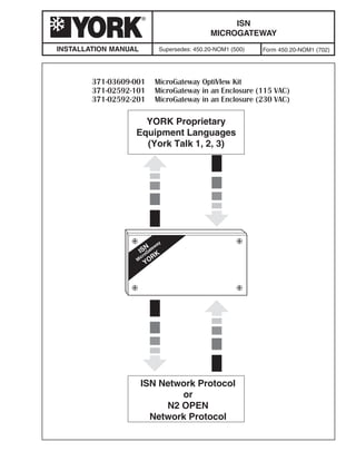
- 1. M icroGateway ISN YORK YORK Proprietary Equipment Languages (York Talk 1, 2, 3) ISN Network Protocol or N2 OPEN Network Protocol INSTALLATION MANUAL ISN MICROGATEWAY Supersedes: 450.20-NOM1 (500) Form 450.20-NOM1 (702)
- 2. 2 YORK INTERNATIONAL FORM 450.20-NOM1 (702) IMPORTANT! READ BEFORE PROCEEDING! GENERAL SAFETY GUIDELINES During installation, operation, maintenance or service, individuals may be exposed to certain components or conditions including, but not limited to: refrigerants, oils, materials under pressure, rotating components, and both high and low voltage. Each of these items has the potential, if misused or handled improperly, to cause bodily injury or death. It is the obligation and responsibility of operating/ service personnel to identify and recognize these inherent hazards, protect themselves, and proceed safely in completing their tasks. Failure to comply with any of these requirements could result in serious damage to the equipment and the property in which it is situated, as well as severe personal injury or death to themselves and people at the site. This document is intended for use by owner-autho- rized operating/service personnel. It is expected that this individual possesses independent training that will enable them to perform their assigned tasks properly and safely. It is essential that, prior to performing any task on this equipment, this indi- vidual shall have read and understood this document and any referenced materials. This individual shall also be familiar with and comply with all applicable governmental standards and regulations pertaining to the task in question. SAFETY SYMBOLS The following symbols are used in this document to alert the reader to areas of potential hazard: DANGER indicates an imminently hazardous situation which, if not avoided, will result in death or serious injury. WARNING indicates a potentially hazardous situation which, if not avoided, could result in death or serious injury. CAUTION identifies a hazard which could lead to damage to the ma- chine, damage to other equipment and/or environmental pollution. Usually an instruction will be given, together with a brief explanation. NOTE is used to highlight additional information which may be helpful to you.
- 3. YORK INTERNATIONAL 3 FORM 450.20-NOM1 (702) CHANGEABILITY OF THIS DOCUMENT In complying with YORK’s policy for continuous product improvement, the information contained in this document is subject to change without notice. While YORK makes no commitment to update or provide current information automatically to the manual owner, that information, if applicable, can be obtained by contacting the nearest YORK Engineered Systems Group office. It is the responsibility of operating/service personnel as to the applicability of these documents. If there is any question in the mind of operating/service person- nel as to the applicability of these documents, then, prior to working on the equipment, they should verify with the owner whether the equipment has been modified and if current documentation is available. REFERENCE INSTRUCTIONS DESCRIPTION FORM NO. ISN MicroGateway Specification 450.20-S06 Data Bridge for BACnet Specification 450.20-S20 Data Bridge for BACnet Installation 450.20-N19 Data Bridge for BACnet Operation 450.20-O5 ISN MicroGateway Revision 8.0 Software Reference Manual 450.20-CP1
- 4. 4 YORK INTERNATIONAL FORM 450.20-NOM1 (702) TABLE OF CONTENTS GENERAL SAFETY GUIDELINES.......................................................................................................... 2 REFERENCE INSTRUCTIONS ............................................................................................................... 3 TABLE OF CONTENTS........................................................................................................................... 4 LIST OF TABLES..................................................................................................................................... 5 LIST OF FIGURES .................................................................................................................................. 6 SECTION 1 – GENERAL INFORMATION............................................................................................... 7 Overview ............................................................................................................................................ 7 Data Bridge MicroGateway .......................................................................................................... 7 SECTION 2 – NETWORK TOPOLOGY .................................................................................................. 9 SECTION 3 – INSTALLATION ............................................................................................................... 13 General ............................................................................................................................................ 13 Environment ............................................................................................................................... 13 Power ......................................................................................................................................... 13 Grounding .................................................................................................................................. 14 High Noise Environments .......................................................................................................... 14 Termination ................................................................................................................................ 15 Protection of Communication Ports ........................................................................................... 15 Cable Specifications ........................................................................................................................ 15 Power Cables ............................................................................................................................. 15 Network Cables .......................................................................................................................... 17 User Selections ................................................................................................................................ 17 Setting the Rotary Switch .......................................................................................................... 17 MicroGateway Jumpers.............................................................................................................. 17 OptiView Installation ........................................................................................................................ 18 Other Chiller Panels ......................................................................................................................... 19 Mounting on a Micro Panel ........................................................................................................ 20 Wall Mounting ............................................................................................................................ 22 Connecting Power ...................................................................................................................... 23 Connecting the Communications Wiring.................................................................................... 24 SECTION 4 – COMMISSIONING .......................................................................................................... 39 Default Settings.......................................................................................................................... 39 How to Use the Node Switch ........................................................................................................... 39 Setting the Network Address ..................................................................................................... 39 Factory Defaults (Address 128) ................................................................................................. 39 Software Features............................................................................................................................ 41 Example ..................................................................................................................................... 42 Configuring to a Micro Panel ........................................................................................................... 42 Type Macro................................................................................................................................. 42 Port 1 Macro............................................................................................................................... 43
- 5. YORK INTERNATIONAL 5 FORM 450.20-NOM1 (702) Port 2 Macro............................................................................................................................... 43 Configuring as a Point-of-Connection.............................................................................................. 43 SECTION 5 – HARDWARE ................................................................................................................... 45 GENERAL ........................................................................................................................................ 45 STATUS LED .................................................................................................................................... 45 Normal Operation....................................................................................................................... 45 Error Conditions ......................................................................................................................... 45 Advisory Conditions ................................................................................................................... 45 System Errors ............................................................................................................................ 45 Port LEDs ......................................................................................................................................... 46 York Talk Communications ......................................................................................................... 46 Dimly Lit LEDs............................................................................................................................ 46 Updating Firmware........................................................................................................................... 47 Part Replacement ............................................................................................................................ 47 Chip Replacement ..................................................................................................................... 47 Fuse Replacement ..................................................................................................................... 48 Power Board Replacement ........................................................................................................ 49 Circuit Board Replacement ........................................................................................................ 50 SECTION 6 – TROUBLESHOOTING .................................................................................................... 53 TABLE OF CONTENTS (CONTINUED) LIST OF TABLES Table 1 – MicroGateway Options .......................................................................................................................... 7 Table 2 – Communication Ports............................................................................................................................ 9 Table 3 – Recommended Cable Specifications .................................................................................................. 16 Table 4 – Available F45 Port Configurations ....................................................................................................... 24 Table 5 – Default Settings................................................................................................................................... 39 Table 6 – Feature List ......................................................................................................................................... 41 Table 7 – STATUS LED Flash Rates .................................................................................................................. 45
- 6. 6 YORK INTERNATIONAL FORM 450.20-NOM1 (702) LIST OF FIGURES Figure 1 – MicroGateway Components ................................................................................................................ 7 Figure 2 – ISN Network Interface ......................................................................................................................... 9 Figure 3 – N2 Network Interface .......................................................................................................................... 9 Figure 4 – ASCII Device Interface ...................................................................................................................... 10 Figure 5 – Typical Board Topology ...................................................................................................................... 10 Figure 6 – Typical Board Topology ...................................................................................................................... 11 Figure 7 – Typical Board Topology ...................................................................................................................... 12 Figure 8 – Additional Ground Conductor ............................................................................................................ 15 Figure 9 – OptiView Mounting ............................................................................................................................ 18 Figure 10 – OptiView Connections ..................................................................................................................... 19 Figure 11 – Enclosure Mounting......................................................................................................................... 21 Figure 12 – Wall Mounting .................................................................................................................................. 22 Figure 13 – Power Connections ......................................................................................................................... 23 Figure 14 – Point-of-Connection for ASCII Interface .......................................................................................... 25 Figure 15 – 1095 Master Board Connections ..................................................................................................... 27 Figure 16 – 1095 Master/Slave Board Connections .......................................................................................... 28 Figure 17 – 776 Board Connections ................................................................................................................... 29 Figure 18 – 940 Board Connections ................................................................................................................... 30 Figure 19 – 1065 Board Connections ................................................................................................................. 31 Figure 20 – 1314 Board Connections ................................................................................................................. 32 Figure 21 – 2050 Board Connections ................................................................................................................. 33 Figure 22 – 1095 to 1793 Board Connections .................................................................................................... 34 Figure 23 – Frick Quantum 1 and 2 Board Connections .................................................................................... 35 Figure 24 – Frick Quantum 3 Board Connections .............................................................................................. 36 Figure 25 – Frick RWB II Board Connections ..................................................................................................... 37 Figure 26 – Setting the Node Switch .................................................................................................................. 40 Figure 27 – EPROM Orientation ........................................................................................................................ 48 Figure 28 – RS485 Drivers ................................................................................................................................. 48 Figure 29 – Power Board Connections ............................................................................................................... 50 Figure 30 – Circuit Board Connections............................................................................................................... 51
- 7. YORK INTERNATIONAL 7 1 FORM 450.20-NOM1 (702) GENERAL INFORMATION SECTION 1 GENERAL INFORMATION Overview The ISN MicroGateway is a communications device that allows any York chiller that supports one of the three York Talk protocols to be connected to an ISN network, N2 network or any device which can translate ASCII. A Building Automation System (BAS) consists of numerous controllers networked together. For reliable communications between various pieces of equip- ment, common communications standards must be in place for each device to share information. A bridge device may be added when translations are needed between different standards and protocols. Several MicroGateway units may be needed on particular BAS sites because of the MicroGateway two-port capabilities. There are three variations of the MicroGateway, depending upon the type of input voltage and the chiller with which it will be connected to. For chillers using the OptiView micro panel, the MicroGateway consists of a single circuit board which is attached to four studs inside the micro panel. The 12 volt DC input power is drawn directly from the OptiView panel, eliminating the need for an external power supply. For other types of chillers, the MicroGateway comes with its own enclosure. In addition to the MicroGate- way circuit board, a power board is included inside the enclosure to convert input AC power (115 or 230 volts) to 12 volt DC power. A series of LEDs provide information about the MicroGateway’s communication and operating status. Each of the two ports have a red transmission LED (TX) and a green receiving LED (RX). Between the two sets of port LED’s is a STATUS LED. The STATUS LED provides information to verify proper setup selection, as well as indications of normal operation versus error modes. For configuration purposes a VT100 terminal emula- tion program is required. While most software programs will work, YORK has available the Micro- Gateway Configurator. To aid in setup of the Micro- Gateway, macros have been developed which set the proper protocols for each port based on the chiller model selected. Data Bridge MicroGateway This manual also covers the Data Bridge MicroGate- way. This version of MicroGateway is specifically configured to interface between a YORK chiller and the Data Bridge for BACnet gateway device. The only difference between the ISN MicroGateway and the Data Bridge MicroGateway is in Feature 6. This was done to maintain software compatibility with earlier BACnet XL products. Feature 6 in the Data Bridge MicroGateway uses the standard ISN Feature 6 (Switched Control) rather than the MicroGateway Feature 6 (Status Values), the same as Features 1 and 5. For specific information on Features, refer to the Rev. 8.0 Software Reference Manual for all MicroGateway products except when referencing Feature 6 in a Data Bridge MicroGateway. For the Data Bridge Micro- Gateway, refer to the Rev. 7 Software Reference Manual. NP TUPNI EGATLOV EPYT yawetaGorciMNSI *100-90630-173 CDV21 tiKweiVitpO 101-29520-173 CAV511 erusolcnE 102-29520-173 CAV032 erusolcnE yawetaGorciMegdirBataD *700-90630-173 CDV21 tiKweiVitpO 701-29520-173 CAV511 erusolcnE 702-29520-173 CAV032 erusolcnE dnaelbacecafretnirellihc,elbacrewop,dracsedulcnI* .)stundnasrehsawnolyn(erawdrahgnitnuom Table 1. MicroGateway Options
- 8. 8 YORK INTERNATIONAL FORM 450.20-NOM1 (702) GENERAL INFORMATION Figure 1 – MicroGateway OptiView Kit Components COMMUNICATION CABLE (Included with OptiView Kit) POWER HARNESS (Included with OptiView Kit) 4 NYLON WASHERS (Included with OptiView Kit) 4 NUTS (Included with OptiView Kit) OPEN 111 2 3 4 5 6 7 8 RN2 RN1ON SW1 1 2 4 8 16 36 64 CM C4 C5 Y1 C15 C19 U5 RN7 R23 C23 R24R25R21R22 TX1 RX1 STATUS TX2 RX2 DS2 DS1 DS5 DS4 DS3 U9 RN12 C16 U2 C25 U14 RN14RN13 U3 C17 C6 R40U8 C22 MICRO GATEWAY 031 - 02039 - REV RN6 U6 RN5 U7 C21RN4 RN3C20 RN8RN11RN10 P1 C29 C27 C28 C26 JP1 JP6JP5 JP2JP3 JP4 1 1 1 9948 CR2 CR3 TB1 RX1 TX1 GND RX2 TX2 GND TB3C13 TB4 CR4 CR5 TB2 U13 C11 U11 C9 + C11 U12 C10 + C12 RN9 C14 VR1 Y2 U4 U10 C18 R53 R44 R55 R54 R43 R42 C24 C2 C3 J1 C1 R1 C7CR1 R2 JP7 R56 C8 R58 CR7 CR6 PORT 1 LED's STATUS LED PORT 2 LED's NODE SWITCH PIN 1 EPROM BACK-UP JUMPER 12 VDC POWER CONNECTOR RS485 PORT 2 RS232 PORT 2 RS485 PORT 1 RS232 PORT 1 PORT 1 RS485 DRIVER PORT 2 RS485 DRIVER
- 9. YORK INTERNATIONAL 9 2 FORM 450.20-NOM1 (702) NETWORK TOPOLOGY SECTION 2 NETWORK TOPOLOGY The MicroGateway essentially consists of two serial communication ports. Each of these ports (Port 1 and Port 2) may be used for either RS232 or RS485 operation. A connection to the appropriate set of terminals is used to make this selection (refer to Table 2). There is always a one-to-one relationship between the MicroGateway and the chiller panel. It is possible to connect only one MicroGateway to one chiller panel. Two chillers require two MicroGateways, etc. NOTE: Only one MicroGateway is required on chillers that make use of a master/slave panel arrangement. When translating to a YORK ISN or JCI N2 network, the appropriate port of the MicroGateway is config- ured, using the MicroGateway Configurator, to communicate using the appropriate protocol. This also selects the communication parameters, i.e. baud rate, parity, etc., to match the protocol chosen. In the case of a network using a protocol other than ISN or N2, the MicroGateway may be configured to communicate using ASCII. This allows the YORK products to communicate with any network for which an ASCII translator is available. The ASCII translator or network controller must be capable of sending and recieving pre-defined packets of ASCII text. 1065 Microboard Optiview Panel w/MicroGateway Card Installed MicroGateway RS485ISNNetwork YT2 M ic ro Gate way IS N YORK 5EDC/LDC Controller Millenium FDC FDC Controller 1065 Microboard Optiview Panel w/MicroGateway Card Installed MicroGateway RS485N2Network M ic ro Gate way IS N YORK YT2 JCI N32 Network Manager Figure 2 – ISN Network Interface Figure 3 – N2 Network Interface Table 2. Communication Ports LEBAL TROP LOCOTORP 1BT 1 584SR 2BT 2 584SR 3BT 1 232SR 4BT 2 232SR
- 10. 10 YORK INTERNATIONAL FORM 450.20-NOM1 (702) NETWORK TOPOLOGY TB1 J1 TB4 USHL +P3-2 -P2-1 GND +5V JP7 LEDS RX1 TX1 GND TB2 NODE SWITCH USHL +P3-1 -P2-1 GND +5V RX2 TX2 GND TB3 EPROM RS232 (19.2 kbaud) OPTIVIEW CHILLER BOARD York Talk 3 ISN M icroGateway YORK RS232 (1200 baud) 776 CHILLER BOARD York Talk 1 ISNorN2 Figure 5 – Typical Board Topology 0 1065 Microboard MicroGateway (configured as a point-of-connection) YT2 0 776 Microboard YT1 Third-Party Control System Network NOTE: This MicroGateway functions in the same manner as the XL Translator. Port1 M ic ro Gate way IS N YORK M ic ro Gate way IS N YORK LINC Chiller Port 1 Port 2 Port2 MicroGateway (configured as a chiller interface) Third-Party Interface with a YORK ASCII driver RS485MultidropNetwork Figure 4 – ASCII Device Interface
- 11. YORK INTERNATIONAL 11 2 FORM 450.20-NOM1 (702) NETWORK TOPOLOGY Figure 6 – Typical Board Topology ISN M icroGateway YORK RS232 (1200 baud) 940 CHILLER BOARD York Talk 1 ISN M icroGateway YORK RS485 (1200 baud) 1065 CHILLER BOARD York Talk 2 Ver. 6 ISN M icroGateway YORK RS485 (4800 baud) 1095 CHILLER BOARD York Talk 2 Ver. 6 1095 CHILLER BOARD SLAVE RS485 (4800 baud) RS485 1095 CHILLER BOARD MASTER ISN M icroGateway YORK York Talk 2 Ver. 6York Talk 2 1095 CHILLER BOARD MASTER RS485 (4800 baud) RS485 1793 I/O BOARD ISN M icroGateway YORK York Talk 2 York Talk 2 Ver. 6 ISNorN2
- 12. 12 YORK INTERNATIONAL FORM 450.20-NOM1 (702) GENERAL INFORMATION Figure 7 – Typical Board Topology ISN M icroGateway YORK RS485 (1200/4800 baud) 1314 CHILLER BOARD York Talk 2 Ver. 6 ISN M icroGateway YORK RS485 (4800 baud) 2050 CHILLER BOARD York Talk 2 Ver. 6 ISN M icroGateway YORK RS485 (1200/4800 baud) FRICK QUANTUM 1 & 2 CHILLER BOARDS York Talk 2 Ver. 6 ISN M icroGateway YORK RS485 (4800 baud) York Talk 2 Ver. 6 FRICK QUANTUM 3 CHILLER BOARD ISN M icroGateway YORK RS485 (1200/4800 baud) FRICK RWBII Plus CHILLER BOARD York Talk 2 Ver. 6 ISNorN2
- 13. YORK INTERNATIONAL 13 3 FORM 450.20-NOM1 (702) INSTALLATION General This manual assumes the installer is competent in environments with moving machinery, and is able to recognize and protect against any inherent hazards, such as, but not limited to, refrigerants, oil, materials under pressure, rotating parts, and both high and low voltages. Each of these items has the potential, if misused or handled improperly, to cause bodily injury or death. It is the obligation and responsibility of the operating/ service personnel to identify and recognize inherent hazards, protect themselves, and proceed safely in completing their tasks. Failure to comply with any of these requirements could result in serious damage to the equipment, as well as severe personal injury or death. In addition to following standard local, state and country codes and procedures, it is recommended that a lockout procedure be used to prevent inadvert- ent start up of equipment during installation and maintenance procedures. All wiring should be carried out in a safe and neat manner and should always comply in all respects to the latest edition of any local, state and country codes that may be applicable. The wiring should be in- stalled in a manner that does not cause a hazard and is protected against electrical and mechanical dam- age. Environment The MicroGateway must be installed in an environ- ment that is protected from the direct influence of the elements and is within the following: Temperature: 32 to 122°F (0 to 50°C). Humidity: 0% to 95% non-condensing. The MicroGateway should never be mounted outside the confines of a building. If this cannot be avoided, it may be mounted inside an enclosure rated at IP65/ NEMA 4X or greater. In addition to protection against the elements, the enclosure must be capable of maintaining the circuit boards at the required temperature and humidity. This may require the addition of a fan or heater to maintain the temperature and humidity inside the enclosure. SECTION 3 INSTALLATION Some micro panels, such as the OptiView, provide a mounting location for the MicroGateway circuit board. These micro panels also provide a power supply for the MicroGateway and utilize a different part number, which does not include a separate power supply. Refer to the documentation included with the chiller. Care should be taken when mounting the MicroGate- way so as not to impede access to other equipment within the vicinity. Power The MicroGateway circuit board is powered from a 12 volt DC supply. When used with an OptiView, this voltage is obtained directly from the micro panel through a power harness supplied with the kit. If the MicroGateway circuit board is installed in its own enclosure, a power supply board is included in the enclosure. Line voltage may be supplied using an external power source or drawn from the input voltage terminal strip inside the chiller micro panel, which is recommended. On all 115 VAC micro panels, the line wire is connected to terminal L and the neutral wire connected to terminal 2. A ground strip or ground points are also located within the micro panel to ensure a common ground. For other micro panels, refer to the chiller documentation. Be sure the VA capacity of the line supplying the chiller micro panel is rated sufficiently for the additional power required by the MicroGateway. Use a suitably-sized wire (refer to the table titled “Recommended Cable Specifications”) to connect the line voltage feed to the MicroGateway. The line voltage power source should be “clean”, separately fused (for either 110 or 220 VAC), and isolated, (using a control transformer) from other equipment in the plant room that may generate EMI interference. All high voltage wiring (>75 volts) must be run in conduit and kept separate from low voltage commu- nications wiring. This will greatly reduce network communication problems.
- 14. 14 YORK INTERNATIONAL INSTALLATION FORM 450.20-NOM1 (702) Grounding For the enclosure style of MicroGateway a ground wire must be connected directly to the chassis at the point of entry. This ensures that the enclosure remains grounded when the power plug is removed. There is a small label that identifies the ground point. This should be connected through a continuous ground circuit to the incoming ground at the source transformer. High Noise Environments Electrical equipment which employs high speed switching circuits (variable speed drives, solid state starters and computing equipment) generate Electro- Magnetic Noise (EMI) and Radio Frequency Interfer- ence (RFI). When excessive, this noise can effect the way electronics behave and, ultimately communica- tion. Noisy environments often show up as varying ground potentials, i.e. the electrical reference points at different nodes are different. This is referred to as “common mode” noise. The RS485 circuitry is designed to withstand a certain defference between varying ground sources. However, if this difference becomes too great and exceeds certain voltage limits, the RS485 circuitry can be permanently damaged and require replacement. To combat these possible problems follow good wiring practices: • Care should be taken to ensure that the micro panel and MicroGateway are powered from a source with true earth ground. • The communication cable should be shielded with the shield terminated at one end only. • Communication cables should not be run in close proximity to or parallel with power cables. The pathways for noise, and therefore the likelihood of common mode noise, are greatly reduced if the MicroGateway is close-coupled to the micro panel (as shown in Figure 10). Close-coupling requires that the MicroGateway and micro panel share the same line voltage power source and are physically close to one another. Typically the MicroGateway is mounted on the micro panel enclosure. This ensures a short communication cable which is usually protected entirely within the two enclosures. The RS485 standard requires three conductors when connecting network nodes together; 2 signal wires and a signal return path. YORK has typically used a twisted-pair cable for the signal wires with the building infrastructure (ground) functioning as the return path. When an application requires the MicroGateway to be mounted remotely from the micro panel and the line voltage power supply obtained from a different location, the building ground may be affected by noise and the signal lost along the return path. In these situations, a separate conductor (outside the shielding) should always be run alongside the stan- dard twisted-pair cable in case there are communica- tion problems. This avoids future installation costs should an additional conductor be required to address communication problems. If communication prob- lems do occur, the additional conductor can be connected to equalize the ground potential. If com- munication operates as expected, the additional conductor is not connected and the building infra- structure operates as the signal return path. CAUTION: Do not connect the additional conductor unless commu- nication problems have been veri- fied. NOTE: The initial purchase and installation cost of an additional con- ductor is minimal compared to the cost of installation at a later date. The additional conductor is recommended due to the frequency of communication problems experienced with remotely mounted equipment. When connecting the conductor to the ground, a small resistor (approximately 100 ohm, 2 watt) should be installed at one end to reduce the magni- tude of current flow in the conductor. GRD. RAM 5
- 15. YORK INTERNATIONAL 15 3 FORM 450.20-NOM1 (702) INSTALLATION Termination On an ISN network (between MicroGateways) a Terminator Module (Part Number 031-01488-000) is required at each network end device. (An end of LAN device can be identified as one that has only one set of ISN LAN wires connected to it.) This provides biasing of the network and assists in returning the signal to a normal state in the event of voltage transients. Protection of Communication Ports When using RS485 technology it is possible that electrical disturbances, such as voltage spikes or stray voltage, can damage a circuit board. The MicroGate- way includes tranzorbs at the RS485 ports to protect against these spikes. Not all micro panels include tranzorbs. Refer to the chiller documentation for recommendations on installing tranzorb protection. Cable Specifications Power Cables CAUTION: Aluminum wire is absolutely not acceptable. For an enclosure style MicroGateway the power cable should be at least an 18 AWG copper wire rated for 10 amps per core at 250 volt AC. If the power cable uses three conductors, the ground conductor must be, as a minimum, the same size with the same current carrying capacity as the live and neutral conductors. USHL +P3-1 -P2-1 GND +5V RS485 J1 USHL +P3-2 -P2-1 GND +5V JP7 LEDS RX1 TX1 GND NODE SWITCH USHL +P3-1 -P2-1 GND +5V RX2 TX2 GND EPROM FUSE FUSE E N L GRD MicroGateway Board (031-02039-xxx) To Line Voltage Power Supply TB2 TB4 TB3 TB1 Port 2 Port 1 Additional Conductor IMPORTANT: The additional conductor must be outside of the RS485 shield. The gauge must be the equivalent or larger than the RS485 conductors P2 and P3 (typically 20 AWG). 100 ohm, 2 watt Resistor (obtain locally) Feed-Through Terminal Blocks (obtain locally) Chiller Micro Panel MicroGateway Figure 8 – Additional Ground Conductor
- 16. 16 YORK INTERNATIONAL INSTALLATION FORM 450.20-NOM1 (702) latigiD stuptuO ,latigiD,golanA stupnIesluP golanAdna stuptuO &NSI(584SR 2klaTkroY )skrowteN otseciveD(232SR dnasCNIL klaTkroY,srellortnoC )skrowteN3&1 egatloVeniL ylppuSrewoP seroCforebmuN rofnro(2 )erocitlum rofnro(2 )erocitlum 2 )riaP-detsiwT( 3 3 rotcudnoCmuminiM )ASC(GWA–eguaG 22 mm43.0( 2 ) 22 mm43.0( 2 ) 02 mm25.0( 2 ) 42 mm02.0( 2 ) 81 mm00.1( 2 ) lairetaMrotcudnoC denniT reppoC denniT reppoC denniT reppoC denniT reppoC nialP reppoC eguagdnartS/dnartS )ASC(GWA 03/7 )mm1.0/7( 03/7 )mm1.0/7( 82/7 )mm21.0/7( 23/7 )mm80.0/7( 03/61 )1.0/61( –gnitaRegatloV U/oU 003 003 003 003 006/003 reptnerruClanimoN spma–eroC 1 5.2 .A.N .A.N 01 dleihS dedleihsnU llarevO%001 liofdleB llarevO%001 liofdleB dediarB%39ro llarevO%001 liofdleB .A.N noitalusnIrotcudnoC CVPdnuoR CVPdnuoR CVPdnuoR CVPdnuoR CVP noitalusnIeroC CVP CVP CVP CVP CVP ecnaticapaClanimoN srotcudnoCneewteb m/Fp– .A.N 08 6.46 801 .A.N citsiretcarahC smho–ecnadepmI .A.N .A.N 87 .A.N .A.N nuRmumixaM )m(tf–htgneL )503(0001 )503(0001 otrefeR krowteN noitceS )01(23 .A.N rebmuNnedleB 2448 1678 2729 3359 AN elbacilppAtoN–.A.N rosteemhcihwgniriwesu,elbissoprevenehW.stnemeriuqermuminimehteradetsilscitsiretcarahcehT:ETON .noitacificepseriwnedleBehtfotnelaviuqeehtsdeecxe Table 3. Recommended Cable Specifications
- 17. YORK INTERNATIONAL 17 3 FORM 450.20-NOM1 (702) INSTALLATION Network Cables In most cases the network cables are specified and provided by a third-party integrator. For the Micro- Gateway to chiller interface, a twisted-pair cable, with an overall shield and drain wire, with conductors being at least 24 AWG is the minimum. For the ISN network (between MicroGateways) a 20 AWG twisted-pair cable with overall shield and drain wire is recommended. User Selections Setting the Rotary Switch Many micro panels use a small rotary switch to set the address of the chiller micro panel on a York Talk network, (York Talk ID address = Rotary Switch + 1). Since the MicroGateway uses a one to one relationship with the chiller panel, this switch is normally set to 0 (York Talk ID address 1) in all cases but that of a master/slave configuration. In this case the master micro panel rotary switch should be set to 0 (York Talk ID address = 1) and the slave micro panel to 1 (York Talk ID address =2). NOTE: The MicroGateway can be programmed to communicate to chillers with different network addresses. Refer to the Operation Manual. If the chiller micro panel is not equipped with a rotary switch, the York Talk ID address (chiller ID) is embedded in the software. In most cases this is user configurable. Some models of chiller use a fixed chiller panel ID which cannot be changed. Refer to the chiller documentation for information on software configuration of the York Talk ID address or chiller ID. MicroGateway Jumpers The MicroGateway is equipped with a jumper (J7) to provide a means of disconnecting the capacitor from the backup circuitry. The jumper should be installed at all times. If removed without power connected, all configurations and setup parameters will be lost.3 4 5 678 2 1 9 0
- 18. 18 YORK INTERNATIONAL INSTALLATION FORM 450.20-NOM1 (702) MicroGateway OptiView Micropanel Washer Nut Figure 9 – OptiView Mounting OptiView Installation When installed in an OptiView enclosure, the Micro- Gateway is typically used to translate the chiller data, in a York Talk format, to either an ISN or N2 format. CAUTION: Always disconnect power to the chiller panel when working inside. Dropped tools and metal chips from drilling can cause short circuits. NOTE: If a previously installed GPIC is determined to be faulty, a MicroGate- way should be installed in its place. The mounting location of the MicroGateway is the same as the GPIC. 1. Disconnect power to the chiller micro panel and follow standard lock out procedures to prevent electrocution and inadvertent activation. 2. Attach the MicroGateway board to the studs in the upper left corner of the OptiView enclosure using the four screws and washers provided. 3. Ensure jumper J27 is set for RS232 (refer to Figure 6 OptiView Connections). 4. Connect the power harness (included with the kit) from J1 on the MicroGateway to J21 on the OptiView micro panel. (Refer to Figure 6 for connection details.) 5. Check for frayed wire strands which could cause a short circuit. Ensure that all components are secure. Refer to the “Connecting the Communications Wiring” for information on connecting the Micro- Gateway to the network.
- 19. YORK INTERNATIONAL 19 3 FORM 450.20-NOM1 (702) INSTALLATION Other Chiller Panels CAUTION: Never install the Micro- Gateway outside the confines of a building unless mounted within another enclosure rated at IP 65/ NEMA 4X or higher. For non-OptiView applications the MicroGateway includes an enclosure with power supply. It does not include communication cables due to the variety of types and lengths which may be required. WARNING: Under no circumstance should the MicroGateway be in- stalled inside a high voltage enclo- sure (>75 volts). This configuration will result in unreliable operation. The MicroGateway enclosure may be mounted inside the chiller micro panel’s low voltage section, if sufficient clearance is available and no local, state or federal codes are violated. Care must be taken to separate the low voltage wiring from the high voltage wiring within the micro panel. The MicroGateway can also be mounted as a stand- alone enclosure, either on the outside surface of the chiller micro panel (close coupled) or on a smooth surface within close proximity of the chiller panel enclosure. Figure 10 – OptiView Connections TB3 NC GND GND GTX GRX DTR1 TXD1 RXD1 DSR1 NC OptiView Micro Board 031-01730 J1 J21 J2 TB4 MicroGateway 031-02039 Power Harness (+12 v DC) USHL +P3-2 -P2-2 GND +5 V JP27 SHIELD LEDSFLASH CARD LEDS BLUE WHITE RX1 TX1 GND TB2 NODE SWITCH EPROM JP7 TB1 RX2 TX2 GND USHL +P3-2 -P2-2 GND +5 V WHITE BLUE SHIELD WHITE BLUE SHIELD BLUE(+) WHITE(–) SHIELD NOTE: ISN network connection shown. For N2 network, connect OptiView board to TB3 and N2 network connects to TB2. Network Wiring
- 20. 20 YORK INTERNATIONAL INSTALLATION FORM 450.20-NOM1 (702) If mounting the MicroGateway on a wall, ensure that the power source is within 3 ft. (0.9 m) of the Micro- Gateway to easily disconnect the power. For mounting on or inside a micro panel, the line voltage power is typically drawn from inside the micro panel. Ensure that the line voltage is sufficient to supply the required power for the MicroGateway and micro panel. Mounting on a Micro Panel CAUTION: Always disconnect power to the chiller micro panel when working inside. Dropped tools and metal chips from drilling can cause short circuits. NOTE: When attaching the MicroGate- way to a micro panel, make sure the MicroGateway does not impede access to other components around the micro panel. 1. Disconnect power to the chiller micro panel and follow standard lock out procedures to prevent electrocution and inadvertent activation. 2. Make sure the MicroGateway enclosure will fit properly and that no obstructions, such as internal boards, switches or external conduit, prevent mounting or servicing of the micro panel. 3. Locate and remove the two plastic caps in the bottom of the MicroGateway enclosure. 4. Mark an appropriate place on the enclosure for a matching set of knock out holes. Mark and drill or punch two holes in the micro panel. CAUTION: Be careful not to dam- age the circuit cards in the Micro- Gateway or micro panel during installation. Protect all circuit boards from metal chips which may cause short circuits if left on the boards at start-up. 5. Using two bulkhead pipe couplers (PN 025- 14158), attach the MicroGateway enclosure to the micro panel. NOTE: Use of the bulkhead pipe couplers will provide sufficient clear- ance to allow removal of the MicroGate- way cover. 6. Complete the wiring as outlined in “Connecting Power” and “Connecting the Communications Wiring.”
- 21. YORK INTERNATIONAL 21 3 FORM 450.20-NOM1 (702) INSTALLATION MicroGateway Enclosure Drill or punch 3/4" (19 mm) Diameter 2x YORK Chiller Micro Panel Alternative Mounting Locations Figure 11 – Enclosure Mounting
- 22. 22 YORK INTERNATIONAL INSTALLATION FORM 450.20-NOM1 (702) Wall Mounting NOTE: When wall mounting the MicroGateway make sure there is no interference with other components in the near vicinity. Use appropriate conduit to connect the power and communications wiring to the Micro- Gateway. 1. Check for proper clearances for the necessary electrical and communications cable runs. Power and communications wiring must comply with all local ordinances and customer require- ments. 2. Select a suitable location and mark the anchor points. Ensure that the enclosure will be level. 3. Drill the appropriate holes in accordance with the type of wall anchor being used. 4. Install the enclosure on the wall. Be careful not to damage the circuit cards during installation. 5. Check that the mounting is secure and the wiring connections are correct and tight. Check that there are no loose wire strands or other metal objects that could cause a short circuit on the circuit board. 6. Complete the wiring as described in “Connect- ing Power” and “Connecting the Communica- tions Wiring.” ISN MicroGateway YORK Chiller Micro Panel 9-1/2" (241.3 mm) 5-3/8" 136.5 mm Template for Mounting on a Wall Conduit MicroGateway Enclosure Figure 12 – Wall Mounting
- 23. YORK INTERNATIONAL 23 3 FORM 450.20-NOM1 (702) INSTALLATION Figure 13 – Power Connections OPEN 111 2 3 4 5 6 7 8 RN2 RN1ON SW1 1 2 4 8 16 36 64 CM C4 C5 Y1 C15 C19 U5 RN7 R23 C23 R24R25R21R22 TX1 RX1 STATUS TX2 RX2 DS2 DS1 DS5 DS4 DS3 U9 RN12 C16 U2 C25 U14 RN14RN13 U3 C17 C6 R40U8 C22 MICRO GATEWAY 031 - 02039 - REV RN6 U6 RN5 U7 C21RN4 RN3C20 RN8RN11RN10 P1 C29 C27 C28 C26 JP1 JP6JP5 JP2JP3 JP4 1 1 1 9948 CR2 CR3 TB1 TB3C13 TB4 CR4 CR5 TB2 U13 C11 U11 C9 + C11 U12 C10 + C12 RN9 C14 VR1 Y2 U4 U10 C18 R53 R44 R55 R54 R43 R4 C24 C2 C3 J1 C1 R1 C7CR1 R2 JP7 R56 C8 R58 CR7 CR6 GND FU2 TB1 ENL BR1 FU1 MICROGATEWAY031-02043-001 POWERBOARDREVA FU1-FASTBLOW1.25A250V FU2-FASTBLOW150MA250V Ground Studs MicroGateway Power Board MicroGateway Circuit Board Chiller Micro Panel Ground Wire Power Harness TB1 Power Connector Line Lead from Power Cable Neutral Lead from Power Cable NOTE: Connect the power leads to appropriate terminals as outlined in the chiller documentation. Terminal Strip1095 micro panel shown Connecting Power When using an enclosure type of MicroGateway, power can be drawn from either a separate power supply or from the main terminal strip in the chiller micro panel. When connecting to a power strip in the chiller micro panel, refer to the chiller documentation to confirm a correct location for connecting. The power source should be protected with a suitable fuse or circuit breaker. Ensure the power is from an uninterrupted source, i.e. not controlled by a pro- grammed switch. If the enclosure is mounted on a wall, the wiring from the power source to the MicroGateway must always be run in a suitable conduit. To obtain the best EMI and EMC performance, care should be taken to ensure that the conduit is bonded to the metal of both enclosures. Scrape the paint around the knockouts, if necessary to provide a better electrical connection between the joining parts. CAUTION: Make sure the power source, whether an external power source or from a chiller panel, is rated sufficiently to support the MicroGateway’s load.
- 24. 24 YORK INTERNATIONAL INSTALLATION FORM 450.20-NOM1 (702) 1. Disconnect power to the chiller micro panel and follow standard lock out procedures to prevent electrocution and inadvertent activation. 2. Connect a 16 - 18 AWG wire from a reliable ground reference to the grounding lug in the MicroGateway’s enclosure using a suitable crimp. Do not remove the existing wire that connects the grounding lug to the power board (031-2043). 3. Remove the input connector at TB1 from the power board. Using a screwdriver or a similar tool, depress the small tabs on the side of the connector and insert the proper wires as labelled on the board (N, L). CAUTION: The ground wire must be connected to the ground stud to ensure the enclosure is grounded if the power plug is disconnected. 4. Check for loose wire strands. Reinsert the connector into the power board. Connecting the Communications Wiring The ports used to connect the MicroGateway depend upon the type of network and the purpose of the MicroGateway. Both ports include connectors for RS232 and RS485. If an ISN network is used, Port 1 connects to the ISN network and the chiller connects to Port 2. If an N2 network is used, Port 2 connects to the N2 network and the chiller connects to Port 1. If the MicroGateway is used as a point-of-connec- tion to an ASCII device, the “chiller network” must be ISN and connected to Port 1. Port 2 then connects to the ASCII device. NOTE: Due to the variety of cables and lengths required, communica- tion cables are not included with any enclosure-style MicroGateways. Be sure the cables used meet standard RS232 or RS485 specifications. The ISN network connections are daisy-chained between devices using RS485 technology. The polarity of each device must be maintained with P3 of one device connected to P3 of the next device and P2 connected to P2. 584SR1troP )1BT( 232SR1troP )3BT( 584SR2troP )2BT( 232SR2troP )4BT( NALNSI 2klaTkroY *NALNSI *2N 2klaTkroY 2N 3ro1klaTkroY 2N NALNSI 3ro1klaTkroY NALNSI IICSA 3ro1klaTkroY IICSA 2klaTkroY IICSA * detroppustonsidnadesuebtondluohsnoitarugifnoctropsihtstcilfnocnoitacinummocoteuD . Table 4. Available F45 Port Configurations
- 25. YORK INTERNATIONAL 25 3 FORM 450.20-NOM1 (702) INSTALLATION TB1 J1 TB4 USHL +P3-2 -P2-2 GND +5V JP7 RX1 TX1 GND TB2 USHL +P3-1 -P2-1 GND +5V RX2 TX2 GND TB3 EPROM WHITE BLUE WHITE BLUE BLUE WHITE Cable to Chiller Micro Panel SHIELD (Open) OPEN 7 6 5 4 3 2 18 1 2 4 8 16 32 64 CM SW1 ON TB1 J1 TB4 USHL +P3-2 -P2-2 GND +5V JP7 RX1 TX1 GND TB2 USHL +P3-1 -P2-1 GND +5V RX2 TX2 GND TB3 EPROM OPEN 7 6 5 4 3 2 18 1 2 4 8 16 32 64 CM SW1 ON WHITE BLUE To next ISN device Connect Third-Party ASCII Device to Port 2 (TB4) NOTE: This MicroGateway functions as an XL Translator. NOTE: This MicroGateway functions as the chiller interface. Non-OptiView connection shown. Connect to TB4 for OptiView chiller. Figure 14 – Point-of-Connection for ASCII Interface
- 26. 26 YORK INTERNATIONAL INSTALLATION FORM 450.20-NOM1 (702) The drain wire of the communication cable must be connected to the equipment ground at one end only. The other end should be connected to either the Unshielded terminal or remain unconnected. Each port has two connectors, one for RS232 and one for RS485. It is possible to connect to two connectors for the same port at the same time but the protocol must be changed to reflect the purpose of the device. For the York Talk protocols, the physical layer is determined by the version of York Talk. Refer to Table for a list of possible connection configurations. NOTE: Figures 14 through 24 show the wiring and jumper settings for specific micro panels. Only the applicable details, i.e. jumpers, connectors, rotary switch, are shown for each board. Each figure shows the LAN network as if connected to an RS485 cable. RS232 can also be used. NOTE: When installing a Micro- Gateway on an older micro panel, please contact York Service Engi- neering to ensure that the software resident in the micro panel is ca- pable of supporting York Talk com- munications. Some older units were not York Talk-ready and may require a software update. 1. Connect the proper type of communications cable to the appropriate ports on the MicroGate- way and route them is a safe manner to the other devices according to all local, state and country codes. 2. Check for frayed wire strands which could cause a short circuit. Ensure that all components are secure. 3. Verify that the chiller ID switch (rotary switch) on the micro panel is set to 0 if the chiller is the master or to 1 if the chiller panel is a slave. NOTE: For York chillers, when the chiller ID is set to 0, the chiller network address is 1. When the chiller ID is set to 1, the chiller network address is 2. For Frick chillers, the chiller ID and the chiller network address are the same. 4. Check the jumpers on any devices, such as the micro panel or controller, for proper settings.
- 27. YORK INTERNATIONAL 27 3 FORM 450.20-NOM1 (702) INSTALLATION Figure 15 – 1095 Master Board Connections TB1 J1 TB4 USHL +P3-2 -P2-2 GND +5V JP7 RX1 TX1 GND TB2 USHL +P3-1 -P2-1 GND +5V RX2 TX2 GND TB3 EPROM FUSE FUSE E N L GRD WHITE BLUE Power Harness (+12 VDC) WHITE BLUE BLUE LAN Cable BAS+ BAS - GND SHLD 485 - 485+ 3 4 5 678 2 1 9 0 S1 031-01095-xxx RS485 RS232 JP19 TB7 TB8 BAS+ (MASTER) WHITE Chiller Cable York Talk 2 V6 RS485 (4800 baud) Jumper Rotary Switch OPEN 7 6 5 4 3 2 18 1 2 4 8 16 32 64 CM SW1 ON Node Switch (Shown at Address 1) SHIELD (Open) WHITE – BLUE + SHIELD (Open) SHIELDSHIELD NOTE: ISN Network connection shown. For N2, connect N2 Cable to TB2 and Chiller Cable to TB1. NOTE: CM on the node switch is equivalent to 128. (YT Address = Rotary Switch + 1)
- 28. 28 YORK INTERNATIONAL INSTALLATION FORM 450.20-NOM1 (702) Figure 16 – 1095 Master/Slave Board Connections TB1 J1 TB4 USHL +P3-2 -P2-2 GND +5VJP7 RX1 TX1 GND TB2 USHL +P3-1 -P2-1 GND +5V RX2 TX2 GND TB3 EPROM FUSE FUSE E N L WHITE BLUE Power Harness (+12 VDC) WHITE BLUE BAS+ BAS - GND SHLD 485– 485+ 3 4 5 678 2 1 9 0 S1 RS485 RS232 JP19 TB7 TB8 BAS+ BLUE WHITE BAS+ BAS - GND SHLD 485 - 485+ S1 031-01095-xxx RS485 RS232 JP19 TB7 TB8 BAS+ (MASTER) (SLAVE) GRD OPEN 7 6 5 4 3 2 18 1 2 4 8 16 32 64 CM SW1 ON Node Switch (Shown at Address 1) 3 4 5 678 2 1 9 0 Chiller Cable York Talk 2 Ver. 6 RS485 (4800 baud) Jumper Rotary Switch Chiller Cable York Talk 2 Ver. 6 RS485 (4800 baud) Jumper Rotary Switch WHITE WHITE BLUE BLUE SHIELD SHIELD (Open) SHIELD (Open) 031-01095-xxx ISN Cable WHITE – BLUE + SHIELD (Open) SHIELD NOTE: ISN Network connection shown. For N2, connect N2 Cable to TB2 and Chiller Cable to TB1. SHIELD NOTE: CM on the node switch is equivalent to 128. (YT Address = Rotary Switch + 1) (YT Address = Rotary Switch + 1)
- 29. YORK INTERNATIONAL 29 3 FORM 450.20-NOM1 (702) INSTALLATION Figure 17 – 776 Board Connections JP56 TB1 J1 TB4 USHL +P3-2 -P2-2 GND +5VJP7 RX1 TX1 GND TB2 USHL +P3-1 -P2-1 GND +5V RX2 TX2 GND TB3 EPROM FUSE FUSE E N L RED BLACK 3 4 5 678 2 1 9 0 S1 PRINT 031-00776-xxx U17 EPROM GREEN J11J8 EMSMODEM GREEN RED OPEN 7 6 5 4 3 2 18 1 2 4 8 16 32 64 CM SW1 ON Node Switch (Shown at Address 1) GRD Power Harness (+12 VDC) Jumper Rotary Switch Chiller Cable York Talk 1 RS232 (1200 baud) SHIELD (Open) GNDTXRX 1 Requires Amp 1-480283-0 Connector BLACK WHITE BLUE ISN Cable WHITE – BLUE + SHIELD (Open) SHIELD NOTE: ISN Network connection shown. For N2, connect N2 Cable to TB2 and Chiller Cable to TB3. NOTE: CM on the node switch is equivalent to 128. (YT Address = Rotary Switch + 1)
- 30. 30 YORK INTERNATIONAL INSTALLATION FORM 450.20-NOM1 (702) Figure 18 – 940 Board Connections GNDTXRX 1 EMSMODEM JP56 TB1 J1 TB4 USHL +P3-2 -P2-2 GND +5V JP7 RX1 TX1 GND TB2 USHL +P3-1 -P2-1 GND +5V RX2 TX2 GND TB3 EPROM FUSE FUSE E N L RED 3 4 5 678 2 1 9 0 S1 031-00940-000 64K 32K JP58 U17 EPROM HS1 JP59 32K 64K GREEN J11 Power Harness (+12 VDC) Jumpers Rotary Switch Chiller Cable York Talk 1 RS232 (1200 baud) OPEN 7 6 5 4 3 2 18 1 2 4 8 16 32 64 CM SW1 ON Node Switch (Shown at Address 1) GRD Requires Amp 1-480283-0 Connector GREEN REDBLACK WHITE BLUE ISN Cable WHITE – BLUE + SHIELD (Open) SHIELD BLACK NOTE: ISN Network connection shown. For N2, connect N2 Cable to TB2 and Chiller Cable to TB3. SHIELD (Open) NOTE: CM on the node switch is equivalent to 128. (YT Address = Rotary Switch + 1)
- 31. YORK INTERNATIONAL 31 3 FORM 450.20-NOM1 (702) INSTALLATION Figure 19 – 1065 Board Connections EPROM GND EMS UI7 TB7 MODEM RS485 RS2323 4 5 678 2 1 9 0 031-01065-xxx S1 JP56 JP58 TB1 J1 TB4 USHL +P3-2 -P2-2 GND +5V JP7 RX1 TX1 GND TB2 USHL +P3-1 -P2-1 GND +5V RX2 TX2 GND TB3 EPROM FUSE FUSE E N L WHITE BLUE WHITE WHITE – BLUE + BLUE WHITE GRD BLUE SHIELD SHIELD (Open) Power Harness (+12 VDC) ISN Cable JumperRotary Switch Chiller Cable York Talk 2 Ver. 6 RS485 (1200 baud) OPEN 7 6 5 4 3 2 18 1 2 4 8 16 32 64 CM SW1 ON Node Switch (Shown at Address 1) SHIELD (Open) SHIELD NOTE: ISN Network connection shown. For N2, connect N2 Cable to TB2 and Chiller Cable to TB1. NOTE: CM on the node switch is equivalent to 128. (YT Address = Rotary Switch + 1)
- 32. 32 YORK INTERNATIONAL INSTALLATION FORM 450.20-NOM1 (702) Figure 20 – 1314 Board Connections 031-01314-000 TB1 J1 TB4 USHL +P3-2 -P2-2 GND +5V JP7 RX1 TX1 GND TB2 USHL +P3-1 -P2-1 GND +5V RX2 TX2 GND TB3 EPROM FUSE FUSE E N L BLUE WHITE SHD GND TB1 V25 GRD OPEN 7 6 5 4 3 2 18 1 2 4 8 16 32 64 CM SW1 ON Node Switch (Shown at Address 1) Power Harness (+12 VDC) Chiller Cable York Talk 2 RS485 Ver. 6 (1200/4800 baud) SHIELD (Open) NOTE: If the EPROM used in the board is dated prior to 11/2000, the York Talk chiller address is fixed at 0 (network address 1). If the EPROM used is dated after 11/2000, the chiller address is software selectable through the micro panel keypad. Refer to the chiller documentation for information regarding the chiller address. NOTE: ISN Network connection shown. For N2, connect N2 Cable to TB2 and Chiller Cable to TB1. WHITE BLUE WHITE BLUE ISN Cable WHITE – BLUE + SHIELD (Open) SHIELD NOTE: CM on the node switch is equivalent to 128.
- 33. YORK INTERNATIONAL 33 3 FORM 450.20-NOM1 (702) INSTALLATION Figure 21 – 2050 Board Connections 031-02050-000 TB1 J1 TB4 USHL +P3-2 -P2-2 GND +5V JP7 RX1 TX1 GND TB2 USHL +P3-1 -P2-1 GND +5V RX2 TX2 GND TB3 EPROM FUSE FUSE E N L BLUE WHITE SHD GND TB1 V25 SHD GND TB6 GRD Power Harness (+12 VDC) SHIELD (Open) OPEN 7 6 5 4 3 2 18 1 2 4 8 16 32 64 CM SW1 ON Node Switch (Shown at Address 1) NOTE: The York Talk chiller address is software-selectable through the micro panel keypad. Set the address to 0 to make the York Talk network address 1. Refer to the chiller documentation for information regarding the chiller ID. NOTE: ISN Network connection shown. For N2, connect N2 Cable to TB2 and Chiller Cable to TB1. WHITE BLUE WHITE BLUE ISN Cable WHITE – BLUE + SHIELD (Open) SHIELD NOTE: CM on the node switch is equivalent to 128. Chiller Cable York Talk 2 RS485 Ver. 6 (1200/4800 baud)
- 34. 34 YORK INTERNATIONAL INSTALLATION FORM 450.20-NOM1 (702) Figure 22 – 1095 to 1793 Board Connections 031-01793-000 TB1 J1 TB4 USHL +P3-2 -P2-2 GND +5VJP7 RX1 TX1 GND TB2 USHL +P3-1 -P2-1 GND +5V RX2 TX2 GND TB3 EPROM FUSE FUSE E N L BLUE WHITE BAS+ BAS - GND SHLD 485 - 485+ SHD GND TB1 V25 SHD GND TB6 3 4 5 678 2 1 9 0 S1 031-01095-000 RS485 RS232 JP19 TB7 TB8 BAS+ BLUE WHITE WHITE BLUE OPEN 7 6 5 4 3 2 18 1 2 4 8 16 32 64 CM SW1 ON Node Switch (Shown at Address 1) GRD Chiller Cable York Talk 2 Ver. 6 RS485 (4800 baud) SHIELD (Open) SHIELD (Open) SHIELD Power Harness (+12 VDC) Jumper Rotary Switch Chiller Cable York Talk 2 Ver. 6 RS485 (4800 baud) NOTE: The 1793 slave chiller ID is always set to the master address +1. WHITE BLUE WHITE BLUE ISN Cable WHITE – BLUE + SHIELD (Open) SHIELD NOTE: ISN Network connection shown. For N2, connect N2 Cable to TB2 and Chiller Cable to TB1. SHIELD NOTE: CM on the node switch is equivalent to 128. (YT Address = Rotary Switch + 1)
- 35. YORK INTERNATIONAL 35 3 FORM 450.20-NOM1 (702) INSTALLATION Figure 23 – Frick Quantum 1 and 2 Board Connections P3 KEYPAD P6 KEYBOARD TEMP SENSOR I/O F1 DP1 OPEN1 8 P2 DIAG J64 J90 J89 P12 P11 P10 COM 1 COM 2 FLOPPY DRV HARD DRVP7 P8 P4 P1 COM DC POWER BAT 640D0061H01 1– 2+ 3 4 5 6 7 8 TB1 J1 TB4 USHL +P3-2 -P2-2 GND +5V JP7 RX1 TX1 GND TB2 USHL +P3-1 -P2-1 GND +5V RX2 TX2 GND TB3 EPROM FUSE FUSE E N L BLUE WHITE GRD SHIELD (Open) Power Harness (+12 VDC) Jumper Chiller Cable York Talk 2 Ver. 6 RS485 (4800 baud) OPEN 7 6 5 4 3 2 18 1 2 4 8 16 32 64 CM SW1 ON Node Switch (Shown at Address 1) WHITE BLUE SHIELD WHITE BLUE ISN Cable WHITE – BLUE + SHIELD (Open) SHIELD NOTE: ISN Network connection shown. For N2, connect N2 Cable to TB2 and Chiller Cable to TB1. NOTE: CM on the node switch is equivalent to 128. NOTE: The chiller ID matches the chiller network address (1=1).
- 36. 36 YORK INTERNATIONAL INSTALLATION FORM 450.20-NOM1 (702) Figure 24 – Frick Quantum 3 Board Connections P5 DISP P4 INV VR1 P6 VGA HEAT SINK P3 KYPD P2 DC POW PL18 P12 PL7 COM1 COM2 COM3 P1 COM2 RS232 FLASH MEMORY SOCKET 1 – 2 + 34 18 BATPL20 COM 1 LK17 LK19 PL7 1 – 2 + 341 – 2 + 34 TB1 J1 TB4 USHL +P3-2 -P2-2 GND +5V JP7 RX1 TX1 GND TB2 USHL +P3-1 -P2-1 GND +5V RX2 TX2 GND TB3 EPROM FUSE FUSE E N L WHITE GRD SHIELD (Open) Power Harness (+12 VDC) Chiller Cable York Talk 2 Ver. 6 RS485 (4800 baud) OPEN 7 6 5 4 3 2 18 1 2 4 8 16 32 64 CM SW1 ON Node Switch (Shown at Address 1) BLUE Jumpers WHITE SHIELD BLUE NOTE: ISN Network connection shown. For N2, connect N2 Cable to TB2 and Chiller Cable to TB1. WHITE BLUE ISN Cable WHITE – BLUE + SHIELD (Open) SHIELD NOTE: CM on the node switch is equivalent to 128. NOTE: The chiller ID matches the chiller network address (1=1).
- 37. YORK INTERNATIONAL 37 3 FORM 450.20-NOM1 (702) INSTALLATION Figure 25 – Frick RWB II Board Connections 1 2 3 4 5 6 7 8 9 +RX -RX +TX -RX GND TB1 J1 TB4 USHL +P3-2 -P2-2 GND +5V JP7 RX1 TX1 GND TB2 USHL +P3-1 -P2-1 GND +5V RX2 TX2 GND TB3 EPROM FUSE FUSE E N L BLUE WHITE GRD Power Harness (+12 VDC) Chiller Cable York Talk 2 Ver. 6 RS485 (4800 baud) SHIELD (Open) OPEN 7 6 5 4 3 2 18 1 2 4 8 16 32 64 CM SW1 ON Node Switch (Shown at Address 1) NOTE: Requires ISN EPROMs in locations U4 and U5. The transfer rate on the chiller must be set to 4800 baud. Frick RWBII Plus Jumpers Jumpers RWBII Rev. B and Lower Connect to Port 1 (9-Pin Connector) 9 3 4 5 8 +RX -RX +TX -RX BLUE WHITE SHIELD (Open) Jumpers RWBII Rev. C and Higher Connect to Port 1 (5 Pin Connector) GND U5 U4 Port 2 Port 1 WHITE BLUE SHIELD WHITE BLUE ISN Cable WHITE – BLUE + SHIELD (Open) SHIELD NOTE: ISN Network connection shown. For N2, connect N2 Cable to TB2 and Chiller Cable to TB1. NOTE: CM on the node switch is equivalent to 128. NOTE: The chiller ID matches the chiller network address (1=1).
- 38. 38 YORK INTERNATIONAL INSTALLATION FORM 450.20-NOM1 (702) THIS PAGE INTENTIONALLY LEFT BLANK
- 39. YORK INTERNATIONAL 39 4 FORM 450.20-NOM1 (702) COMMISSIONING SECTION 4 COMMISSIONING The MicroGateway Configurator is a windows-based VT100 terminal emulation program developed by York International. This software, formerly known as ISNTools, uses text-based macros to load parameters for each type of chiller micro panel. The software is available on a CD from YORK BAS. Contact a local York Service/Sales office for further information. NOTE: Do not apply power to the unit before reading this section. To commission the MicroGateway, a computer and communications cable are required. The computer operates the software interface (VT 100 emulation) and the cable connects to the MicroGateway. The cable connects to the RS232 port on the computer (DB-9 or DB-25 connector) and to the RS232 port on the MicroGateway (TB4). To install the software, insert the CD in the CD-ROM drive on the computer. Follow these instructions to install the software. 1. Click the Start button located on the left side of the Windows Taskbar and select Run. 2. Click the Browse button and locate the CD- ROM drive using the drop-down box (usually D). 3. Select the file Config Setup.exe by clicking the Open button. 4. Click the OK button once to start the install program. Follow the instructions on the screen. Additional information is found in the help file located on the CD. Default Settings When shipped from the factory, the MicroGateway is set up as shown in Table 4. Table 5. Default Settings LOCOTORP NOITACINUMMOC 1TROP NSI77veR dnaduabk05 ytirapddo 2TROP lanimreT noitacinummoc dnaduabk6.9 ytirapon How to Use the Node Switch The node switch enables a user to set a unique network address. It consists of eight individual DIP switches that are binary weighted. Summing the value of each of these switches in the ON position forms the decimal value of the node switch. To determine the numeric value assigned to the switch, add the numbers above the corresponding DIP switches which in the ON position. The resulting sum is the number (address) selected. Setting the Network Address The network node number should be selected so it is unique on the network. ISN allows network address from 1 to 99. N2 allows addresses from 1 to 255, excluding 128. Factory Defaults (Address 128) The node switch has one additional function. When the MicroGateway is powered up and the address set to 128, it reconfigures the software, stored in E², to the default settings, stored in the EPROM, (original factory defaults unless a new EPROM was burned). In addition to any port settings which may have been changed, all other software features that have been edited revert to the defaults stored in the EPROM. CAUTION: It is highly recom- mended that the reset process be invoked whenever chiller profiles are changed. This clears items not overwritten by activating a macro in the MicroGateway Configurator.
- 40. 40 YORK INTERNATIONAL FORM 450.20-NOM1 (702) COMMISSIONING OPEN 7654321 8 1 2 4 8 16 32 64 CM SW 1ON Address 255 NOTE: Black circle indicates depressed side. CM is equivalent to 128. 1+2+4+8+16+32+64+128=255 Side view of depressed rocker switchesOPEN 7654321 8 1 2 4 8 16 32 64 CM SW 1ON 1+2+0+0+16+0+0+128=147 Address 147 Figure 26 – Setting the Node Switch NOTE: The 128 reset feature is in- cluded in products using software revision level 17g and higher. To reset the MicroGateway to the defaults: 1. Remove the power harness from J1 to disconnect power. 2. Disconnect the communications wiring at Port 1 and Port 2. 3. Corrupt the SRAM by removing the capacitor enable jumper from location JP7 for a minimum of 10 seconds. 4. Install the jumper at JP7. 5. Set the node switch to address 128. 6. Connect the power harness to J1 to reconnect power. 7. Observe the STATUS LED. While data is transferring, the STATUS LED flashes at a rate of 3 times per cycle. When the data transfer is complete, it flashes at a rate of one flash per cycle (a cycle is approximately 1.2 seconds). NOTE: Only data that has been changed is transferred. If few changes have been made, the transfer rate may take less than a second and the 3 flashes will not be observed. 7. Remove the power harness from J1. 8. Set the node switch to the desired network address. 9. Connect the power harness to J1 to reconnect power. 10. Reconnect the communications wiring at Ports 1 and 2 in the same manner as previously removed in Step 2.
- 41. YORK INTERNATIONAL 41 4 FORM 450.20-NOM1 (702) COMMISSIONING Software Features The MicroGateway uses the “Feature-Section-Page” layout for programming the software. Many of the commands are the same as the full ISN software feature set. However, the feature list has been custom- ized to suit the specific requirements of the Micro- Gateway. This software set is referred to as Rev. 8.0. The features and number of sections available in the MicroGateway is summarized in Table 4. For details on each Feature, refer to Software Reference Manual Rev. 8. NOTE: The Analog Values (F02, F04, F07 and F09) and Digital Status (F01, F05 and F06) provide the same func- tion but are in series to allow sufficient points for communication. The MicroGateway’s software is organized into discreet functional modules called features. Each feature is a self-contained set of routines that are designed to perform a specific task or set of tasks. For example, F53 (York Talk 3) is used to exchange data between the MicroGateway and the OptiView micro panel. F45 (Port Configuration) is used to assign different protocols to the MicroGateway’s ports. Some features are made extensible though the use of sections. Each section is another set of the same functions. For example, F54 (York Talk 2) has two sections. Section 1 is used to connect chillers that only have enough data to populate one section. Section 2 is an identical functional copy of Section 1 used by applications that require greater data capac- ity. Every feature is further subdivided into pages. A page represents a finite attribute or set of attributes for a specific aspect of the features function. For example, page 4 of F45 (Port Configuration) displays the type of protocol configured on Port 2. To build a unique application a user edits the required features, sections and pages. The edited features collectively represent the application for a specific need. (This is sometimes referred to as the Applica- tion Overlay.) The language syntax used is expressed as fnn – Represents a feature, such as f45, where nn represents a number. snn – Represents a section, such as s01, where nn erutaeF rebmuN noitpircseD forebmuN snoitceS 10 sutatSlatigiD 99 20 eulaVgolanA 99 30 elbairaVmetsyS 99 40 eulaVgolanA 99 50 sutatSlatigiD 99 60 sutatSlatigiD 99 70 eulaVgolanA 99 80 cigoLlanoitidnoC 99 90 seulaVgolanA 99 01 radnelaCmetsyS 10 31 elbaTpu-kooL 80 02 DELsutatS 10 82 refsnarTgolanA 48 92 refsnarTlatigiD 48 13 margorPemiT 80 33 eludehcSemiT 40 93 kcolretnIgolanA 99 04 kcolretnIlatigiD 99 54 noitarugifnoCtroP 10 64 sutatSkrowteN 10 84 noitarugifnoCtropeR 03/01 94 epyTresU 21 05 scitsongaiDmetsyS 10 25 1klaTkroY 10 35 3klaTkroY 40 45 2klaTkroY 20 55 gnixelpitluM 80 65 gnixelpitluM-eD 40 75 puorGkrowteN 01 85 puteS²E 02 95 ataD²E 02 06 erutcurtSmetsyS 10 16 paMgolanA2N 10 26 paMlatigiD2N 10 Table 6. Feature List represents a number. pnn – Represents a page, such as p04, where nn represents a number. NOTE: Always use lower case when typing commands into the MicroGate- way Configurator (ISNtools). Use upper case when typing labels into text fields.
- 42. 42 YORK INTERNATIONAL FORM 450.20-NOM1 (702) COMMISSIONING To edit a field within a page, “open” the page for editing by typing e <Return> To proceed to each subsequent field type e <Return> If a field requires a number variable to be entered, it is indicated by vvv. A text field is indicated by tt...t and a menu selections is indicated by mm...m. To toggle through the menu items type m <Return> Once the desired item is shown on the screen, con- firm the choice by typing e <Return> to select it. A help screen can be accessed by typing help <Return> at the prompt after logging on to the MicroGateway. Example The following example shows how to view and edit the communications settings on Port 1. 1. Connect to the MicroGateway and logon. Refer to the instructions in Section 2 for details. 2. Type f45p03 <Return> Screen response P03 PORT 1 PROTOCOL: YORK TALK 3 The unit enters Feature 45, Page 3 and responds with the current setting. 3. To change the setting, type e <Return> Screen response mmmmmmmm The field is “opened” for editing. When mm...m is displayed it indicates the field has a menu list of choices. For other fields vv...v may be displayed, which indicate a value must be entered. When tt...t is displayed, text may be typed into the field. 4. To cycle through the menu type m <Return> Screen response: P03 PORT 1 PROTOCOL: YORK TALK 2 V4 1200 which is the next choice on the menu. Continue cycling through the list until the desired choice appears on the screen. When the desired choice appears close the edit by typing e <Return> Screen response: P03 PORT 1 PROTOCOL: YORK TALK 2 V4 4800 For pages with multiple fields, each subsequent e <Return> selects the next field. Configuring to a Micro Panel After the MicroGateway Configurator is installed and a computer is connected to the MicroGateway, it can be configured using MicroGateway Configurator. To start the MicroGateway Configurator follow the instructions on the CD. The MicroGateway Configurator allows the user to choose from a selection of macros specific to the various chiller micro panels available from YORK. As each chiller profile is selected, the proper commu- nication parameters are loaded in the MicroGateway. There are three drop-down boxes which list the micro panel choices. Type Macro The Type macro selects the type of protocol to be used and the number of sections within the software (Feature 45). The number of sections selected matches the protocol with York Talk 1 using a single section, York Talk 2 using two sections and York Talk 3 using 4 sections. The Type macro also loads the points for the specific micro panel chosen (Feature 52, 53 or 54). These points are stored in the EPROM according to the standard points list. NOTE: For OptiView micro panels, the macro first loads all the OptiView points. A second macro then adjusts the points list to fit the specific model of OptiView (YK, YS, YT).
- 43. YORK INTERNATIONAL 43 4 FORM 450.20-NOM1 (702) COMMISSIONING Port 1 Macro The Port 1 macro sets the specific communication protocol for Port 1 according to the chosen micro panel (Feature 45 Page 03). Port 2 Macro The Port 2 macro sets the specific communication protocol for Port 2 according to the chosen micro panel (Feature 45 Page 04). NOTE: The Help document on the CD lists the commands performed (Feature-Section-Page) for each macro. If desired, the settings may be performed manually using any VT100 terminal emulation program, such as ProComm® from Symantic® or HyperTerminal. Configuring as a Point-of-Connection When the MicroGateway is used as a point-of- connection device, it must be configured to allow a given amount of access by the third-party ASCII device. The ASCII devices typically use a password of 1 to access data. With this user-level password, the number of Features available to the ASCII device are limited to the five which contain relevant data. To setup this user-level password log on to the MicroGateway using the MicroGateway Configurator. In Feature 60, Section 1, Page 06, change the pass- word to 1 and the Feature Extent to 5. 1. Connect to the MicroGateway and logon. Refer to the instructions in Section 2 for details. 2. Type f60s01p06 <Return> Screen response P06 PASSWORD1 1 FEATURE EXTENT 5 The MicroGateway will now respond when the ASCII device communicates to it, allowing access to Fea- tures 1 through 5 only, which is where the required data resides.
- 44. 44 YORK INTERNATIONAL FORM 450.20-NOM1 (702) COMMISSIONING THIS PAGE INTENTIONALLY LEFT BLANK
- 45. YORK INTERNATIONAL 45 5 FORM 450.20-NOM1 (702) HARDWARE SECTION 5 HARDWARE GENERAL The MicroGateway has five LEDs that are used as indicators of communication and operating status. Two LEDs are associated with each communication port and indicate when the MicroGateway is receiv- ing or transmitting information. The STATUS LED indicates proper operation of the MicroGateway. STATUS LED Normal Operation When the ISN MicroGateway is working properly, the STATUS LED flashes continuously approxi- mately once per second. The transmit and receive LEDs flash when information is transferred to or from each port. Error Conditions If the STATUS LED flashes several times within a cycle (a cycle is a number of flashes and a 3 second off time), an error condition is present. This cycle will continue to indicate the error condition until the cause of the condition is removed. The STATUS LED has nine flash rates to indicate error conditions. Flash rates from 10 to 99 may be configured by the user to indicate specific error conditions. Refer to the Software Reference Manual for additional informa- tion on configuration of Feature 20 – STATUS LED. NOTE: System flash rates (1 through 9) always takes precedence over user- configured flash rates. Advisory Conditions Several of the flash codes can be considered advisory. They provide an indication that the MicroGateway is not functioning due to its operational state or a network communications failure rather than a Micro- Gateway error. Two (2) flashes per cycle indicate the MicroGateway is unconfigured. No applications are installed or programming is not implemented. Three (3) flashes per cycle indicate the system is halt or in monitor mode (Feature 60) and applications are not being processed. Four (4) flashes of the STATUS LED indicate a York Talk communication failure between the chiller micro panel and the MicroGateway. The condition could be due to faulty wiring, incorrect setup of the chiller or simply an unplugged network cable. For any York Talk features enabled in Feature 45 but not opera- tional, i.e. sending and receiving messages correctly, the STATUS LED flashes 4 times per cycle. Five (5) flashes per cycle indicate the MicroGateway node switch is set to 255 for terminal communica- tions. System Errors A system error is an error that will not allow the MicroGateway to operate correctly. This is indicated by a single flash per cycle. If the MicroGateway's hardware seriously malfunc- tions, the watchdog circuit will not be updated and the STATUS LED flashes in unison with the proces- sor reset signal. This is typically once every 1.5 SEHSALF SETACIDNI NOroFFOydaetS MORPE,srorrEerawdraH EroeruliaF 2 *eruliaF 1 rorrEmetsyS 2 derugifnocnUmetsyS 3 tlaHnimetsyS edoMrotinoMro 4 klaTkroY eruliaFnoitacinummoC 5 detceleS552hctiwSedoN 9hguorht6 devreseR ehtseriuqerhcihwrorreerawdraHlataFasetacidnI* .decalpereboterawdrah Table 7 – STATUS LED Flash Rates
- 46. 46 YORK INTERNATIONAL FORM 450.20-NOM1 (702) HARDWARE seconds. The STATUS LED continues to flash until the watchdog circuit once again starts to be updated by the system. A serious hardware malfunction would be character- ized by the failure of the processor, SRAM, E² or EPROM (or the removal of the EPROM). A catastrophic hardware failure may leave the STA- TUS LED either in the ON or OFF state. This situation could be caused by the above mentioned hardware malfunctions, a malfunctioning power supply, system error condition or communications test failure. System errors can result from an intermit- tent hardware failure (the result of electrical noise) which can corrupt the system's memory, resulting in unpredictable behavior. A user usually cannot determine the difference between a system error and a catastrophic failure. If the STATUS LED is observed to be either perma- nently ON or OFF, the user should de-configure the MicroGateway by disabling the capacitor to clear out the contents of the SRAM and performing the Power Down/Power Up. This may cure the problem if it was due to a hardware glitch. Otherwise, the MicroGate- way may need to be replaced. Port LEDs Each communication port is supported with two diagnostic LEDs. The red LEDs show transmissions while the green LEDs show data reception. York Talk Communications When communicating to a device using a York Talk protocol, the port begins transmitting requests to the micro panel. Even if there is no micro panel actually connected to the MicroGateway, the MicroGateway attempts to communicate. The types of exchanges are listed below: York Talk 1 Connection (RS232) – The red TX LED flashes for a couple of seconds and then the whole process will be repeated every Poll Time, (currently this defaults to 30 seconds). If a micro panel is connected to the MicroGateway it responds with a reply message causing the green RX LED to flash for about 10 seconds, although this depends upon the type of chiller. York Talk 2 Connection (RS485) – The red TX LED and the green RX LED flashes together for a couple of seconds and then the whole process is repeated every Poll Time, (the Poll Time default is 30 seconds). If a micro panel is connected to the MicroGateway it responds with a reply causing the green RX LED to flash for about 20 seconds, although this depends upon the type of chiller. The TX and RX LEDs flash together because TX and RX lines are connected through the RS485 transceiver. When the MicroGateway transmits a message it also receives it. York Talk 3 Connection (RS232) – The LED pattern is very much dependent if an OptiView micro panel is connected or not. a. On power up the MicroGateway requests the time from the OptiView micro panel. The user can observe the red TX LED flashing during this process. If the micro panel responds with the time, indicated by green LED flashes, the MicroGateway assumes the communication link is established. The MicroGateway then proceeds to send the engineering units to the micro panel and wait for a positive acknowledgement. Once this is received the MicroGateway proceeds with normal operation. b. If no acknowledgement is received after three attempts, the MicroGateway assumes the communication link is bad and starts requesting the time from the micro panel. Simultaneous red and green LED flashes characterize normal communications. Dimly Lit LEDs Sometimes the green RX LED on the MicroGateway monitoring an RS485 transceiver may appear to be dimly illuminated, even if there is no activity on the network. This is an indication that the bias of the transceiver is being affected. There are usually two reasons for this type of problem; a constant electrical coupling onto the network wires or a defective RS485 transceiver. To ensure that the problem is not related to an installation problem: • Ensure that no high voltage electrical signals are in close proximity to the MicroGateway.
- 47. YORK INTERNATIONAL 47 5 FORM 450.20-NOM1 (702) HARDWARE • Provide a good ground connection for the MicroGateway. If a defective transceiver requires replacement refer to the procedure shown later in this section. Updating Firmware Occasionally, it may be necessary to upgrade the firmware in the MicroGateway or reset the configura- tion to the default, factory setting. A routine can be selected by setting the node switch to 128 which forces the MicroGateway to use the default configura- tion stored in EPROM. Normally the current settings are retrieved from E2 each time the MicroGateway is started. When node address 128 is selected the priority of the information which is loaded in SRAM is changed. Information is retrieved from the EPROM first and then the informa- tion stored in E2 is overwritten by the EPROM defaults. A STATUS LED flash rate of 3 flashes per cycle indicates the MicroGateway is transferring data from the EPROM. When complete, the STATUS LED flashes at a once per cycle rate. WARNING: Personnel should always be grounded before touching the MicroGateway. An Anti-Static Ground Strap is recommended. As a minimum, firmly grasp grounded metal before working on the unit. To update the firmware: 1. Remove the power to the MicroGateway by pulling the power harness from J1. 2. Remove the Capacitor Enable jumper at JP7 for a minimum of 10 seconds. This corrupts the SRAM memory. 3. Install the Capacitor Enable jumper at JP7. 4. If necessary, remove the EPROM using a removal tool. Carefully install the new EPROM, making sure pin 1 is located properly. 5. Set the node switch to 128. 6. Insert the power harness into connector J1. The STATUS LED should flash 3 times per cycle. NOTE: If the update process is short (not much data to transfer) the 3 flashes may not be visible. 7. When the STATUS LED begins to flash once per cycle, the MicroGateway can be configured using either a Quick Start address or connecting a computer terminal. Part Replacement Certain items can be replaced if found to be malfunc- tioning. Typical items are the RS485 drivers (trans- ceivers), EPROM Circuit Board or Power Board. Chip Replacement DANGER: Always disconnect the line voltage to the MicroGateway before removing any components. WARNING: Personnel should always be grounded before touching the MicroGateway. An Anti-Static Ground Strap is recommended. As a minimum, firmly grasp grounded metal before working on the unit. NOTE: If upgrading the software to a new version, refer to the section on UPDATING FIRMWARE. To replace either the EPROM or the RS485 drivers (transceivers): 1. Disconnect the line voltage power supply to the MicroGateway. 2. Note the position of the notch in the chip. Using a chip removal tool, remove the chip from the MicroGateway card.
- 48. 48 YORK INTERNATIONAL FORM 450.20-NOM1 (702) HARDWARE 3. On the replacement chip, locate the notch. Carefully install the replacement chip in the socket with the notch in the same location as noted during removal. NOTE: The notch indicates the location of pin 1 on the chip. 4. Reconnect the line voltage power supply. If necessary, reconfigure the MicroGateway using the MicroGateway Configurator. Fuse Replacement For MicroGateways within their own enclosure (non- OptiView units) the Power Board is protected by two fuses. The fuse in location FU1 is a 5 x 20 Fast-Blow, 1.25 A, 250 volt fuse. It protects the board against circuit overload on the low voltage side of the Power Board. The fuse in location FU2 is a 5 x 20 Fast- Blow, 150 mA, 250 volt fuse. It protects the Micro- Gateway transformer from overload. DANGER: Always disconnect the line voltage to the MicroGateway before removing any components. WARNING: Personnel should always be grounded before touching the MicroGateway. An Anti-Static Ground Strap is recommended. As a minimum, firmly grasp grounded metal before working on the unit. NOTE: Inserting a replacement fuse with no power connected may cause the LED to illuminate momentarily due to the energy stored by capacitor on the Power Board. JP1 JP6JP5 JP2JP3 JP4 1 1 1 9948 CR2 CR3 TB1 RX1 TX1 GND RX2 TX2 GND TB3C13 TB4 CR4 CR5 TB2 U13 C11 U11 C9 + C11 U12 C10 + C12 VR1 RS485 PORT 2 RS232 PORT 2 RS485 PORT 1 RS232 PORT 1 PORT 1 RS485 DRIVER PORT 2 RS485 DRIVER NOTCH NOTCH Figure 28 – RS485 Drivers C5 Y1 C19 U5 RN7 RN6 U6 RN5 U7 C21RN4 RN3C20 U10 C18 R53 R44 R55 R54 C24 R56 C8 R58 CR7 CR6 PIN 1 EPROM NOTCH Figure 27 – EPROM Orientation
- 49. YORK INTERNATIONAL 49 5 FORM 450.20-NOM1 (702) HARDWARE If the Power Board is suspected of malfunctioning: 1. Disconnect the line voltage power supply to the MicroGateway. 2. Remove the power harness from J1 to discon- nect power. 3. Place probes from a voltmeter into the power harness plug. 4. Reconnect the line voltage power supply to the MicroGateway. Note the voltage at the power harness connector. Voltage should be in the range of 12 to 30 volts DC. a. If the voltage measures within this range, the Power Board is functioning properly. b. If not proceed to step 5. 5. Disconnect the line voltage power supply to the MicroGateway. 6. Reconnect the power harness to connector J1. This will discharge any stray voltage remaining on the Power Board capacitor. 7. Remove the fuse covers and fuses on the Power Board. Install new fuses of the appropriate size. NOTE: It is recommended that both fuses be replaced if either is question- able. 8. Reconnect the line voltage power supply to the MicroGateway. If the MicroGateway fails to work, proceed to the Power Board Replacement procedure. Power Board Replacement DANGER: Always disconnect the line voltage to the MicroGateway before removing any components. WARNING: Personnel should always be grounded before touching the MicroGateway. An Anti-Static Ground Strap is recommended. As a minimum, firmly grasp grounded metal before working on the unit. For MicroGateways with their own enclosure (non- OptiView units) the Power Board can be replaced if it is determined to be faulty. Before replacing the board, check the two fuses located on the board. To replace the board: 1. Disconnect the line voltage power supply to the MicroGateway. 2. Remove connector TB1 (line voltage supply) from the Power Board. 3. Remove the power harness from J1 on the circuit board to disconnect power. 4. Remove the four screws and washers securing the Power Board to the enclosure. Note that two of the screws also secure ground wires to the board. Remove the board. 5. Position the replacement board in the enclosure and secure with the two screws and washers which did not also secure ground wires. 6. Insert and tighten the screws and washers which secured the ground wires to the enclosure and enclosure cover.
- 50. 50 YORK INTERNATIONAL FORM 450.20-NOM1 (702) HARDWARE 7. Connect the line voltage supply cable to TB1 on the Power Board. 8. Apply the normal line voltage supply to the Power Board. Check to make sure operation seems normal. 9. Place the power connector into J1 on the circuit board. Check to make sure operation seems normal. Circuit Board Replacement If the circuit board is found to be faulty, it can be replaced. It is recommended that the EPROM be removed from the faulty board and reinstalled into the new, replacement board. NOTE: If the circuit board is faulty, the EPROM may still function properly. By removing the EPROM, the original version of the software can be retained. TB1 J1 TB4 USHL +P3-2 -P2-1 GND +5V JP7 LEDS RX1 TX1 GND TB2 NODE SWITCH USHL +P3-1 -P2-1 GND +5V RX2 TX2 GND TB3 EPROM FUSE FUSE E N L GRD Power Harness (+12 volt DC) Power Supply Cable (+110 or 220 volt AC) Board Ground Wire Orange Connector Power Board (031-02043) MicroGateway Board (031-02039) Ground Stud Figure 29 – Power Board Connections
- 51. YORK INTERNATIONAL 51 5 FORM 450.20-NOM1 (702) HARDWARE If the EPROM is found to be faulty, refer to the section on upgrading firmware. To replace the circuit board: 1. Disconnect the line voltage power supply and network cables to the MicroGateway. 2. Remove the connector J1 from the circuit board or from the OptiView micro panel power source. 3. Using a chip removal tool, remove the EPROM from socket U6. 4. Remove the four screws securing the board to the enclosure or OptiView micro panel. 5. Position the replacement circuit board in the enclosure or OptiView micro panel. Secure with four washers and screws. OPEN 111 2 3 4 5 6 7 8 RN2 RN1ON SW1 1 2 4 8 16 36 64 CM C4 C5 Y1 C15 C19 U5 RN7 R23 C23 R24R25R21R22 TX1 RX1 STATUS TX2 RX2 DS2 DS1 DS5 DS4 DS3 U9 RN12 C16 U2 C25 U14 RN14RN13 U3 C17 C6 R40U8 C22MICRO GATEWAY 031 - 02039 - REV RN6 U6 RN5 U7 C21RN4 RN3C20 RN8RN11RN10 P1 C29 C27 C28 C26 JP1 JP6JP5 JP2JP3 JP4 1 1 1 9948 CR2 CR3 TB1 RX1 TX1 GND RX2 TX2 GND TB3C13 TB4 CR4 CR5 TB2 U13 C11 U11 C9 + C11 U12 C10 + C12 RN9 C14 VR1 Y2 U4 U10 C18 R53 R44 R55 R54 R43 R42 C24 C2 C3 J1 C1 R1 C7CR1 R2 JP7 R56 C8 R58 CR7 CR6 PORT 1 LED's STATUS LED PORT 2 LED's NODE SWITCH PIN 1 EPROM BACK-UP JUMPER 12 VDC POWER CONNECTOR RS485 PORT 2 RS232 PORT 2 RS485 PORT 1 RS232 PORT 1 PORT 1 RS485 DRIVER PORT 2 RS485 DRIVER Figure 30 – Circuit Board Components 6. Install the EPROM previously removed. NOTE: If a new EPROM is to be installed, refer to Upgrading the Firm- ware. 7. Connect the power to connector J1. 8. Turn on the line voltage supply and check for proper operation. 9. Reinstall any covers removed to gain access to the circuit board.
- 52. THIS PAGE INTENTIONALLY LEFT BLANK
- 53. This section provides a guide for troubleshooting should a problem develop. A chart has been created to help in diagnosis of faults. To use the chart, locate the appropriate symptom and review the possible causes for that symptom. After the most likely cause is determined, follow the suggestions listed in the solutions column. While this Troubleshooting Guide does not claim to include all possible symptoms or solutions, it can simplify troubleshooting and assist in determining the causes of a malfunctioning device. SECTION 6 TROUBLESHOOTING
- 54. SYMPTOM PROBABLE CAUSE SOLUTION STATUS LED does not light. No power to the unit. Blown fuse. Malfunctioning Power Board. EPROM removed from board Port not setup correctly. Chiller micro panel not communi- cating. Malfunctioning RS485 driver (applies to RS485 communications only). Incorrect wiring at connector. RX and TX swapped. Port not set correctly. Third-party device not communicat- ing. Malfunctioning RS485 driver (applies to RS485 communications only). Incorrect wiring at connector. RX and TX swapped. Third party attributes not set correctly. Query request out of range. Check power supply for correct voltage (110 or 220 v AC). Ensure line voltage power supply is turned “on.” Replace both fuses. Check for 12 volts DC at J1. Replace defective components. Install EPROM. Ensure that port settings are correct. Ensure chiller is configured cor- rectly. Refer to chiller documenta- tion. Replace RS485 driver. Ensure wires are installed properly. Ensure wires are installed properly. Ensure that port settings are correct. Ensure third party device is config- ured correctly. Refer to the third- party documentation. Replace RS485 driver. Ensure wires are installed properly. Ensure wires are installed properly. Third party address and object attributes are not set correctly. Refer to third party documentation. Check scale and range calculations. Check query for number of points requested. Chiller TX1/RX1 LEDs do not flash (observe for a minimum of 30 seconds). Third party TX2/RX2 LEDs do not flash. Third party is communicating but some values are suspected to be incorrect. Exception status returned.
- 55. Incorrect wiring to OptiView micro panel. Jumper not installed in JP27 on micro panel. OptiView micro panel is not configured for ISN communica- tions. Faulty OptiView micro panel. Faulty MicroGateway. Low input supply voltage. No EPROM. Faulty MicroGateway. Correct the wiring. Install jumper. Refer to Installation Manual. Configure micro panel to use ISN as the source. Replace micro panel. Replace MicroGateway. Measure voltage at J1 to ensure it is greater than 12 volt DC. If not, replace Power Board or power source at micro panel. Replace or install EPROM. Replace MicroGateway. STATUS LED flashes once every 2 seconds. SYMPTOM PROBABLE CAUSE SOLUTION York Talk 3 TX (red) LED blinks continuously.
- 56. P.O. Box 1592, York, Pennsylvania USA 17405-1592 Unit 1, Red Shute Hill, Hermitage, Newbury, Berks RG18 9QL United Kingdom Tele. 800-861-1001 website: www.york.com Tele: +44 (0)1635 202200 e-mail: controls.sales@uk.york.com Copyright © by York International Corporation 2002 Subject to change without notice. Printed in USA Form 450.20-NOM1 (702) ALL RIGHTS RESERVED Supersedes: 450.20-NOM1 (500)