
Recommended
More Related Content
Similar to trickling filters_lecture.ppt
Similar to trickling filters_lecture.ppt (20)
Recently uploaded
Recently uploaded (20)
trickling filters_lecture.ppt
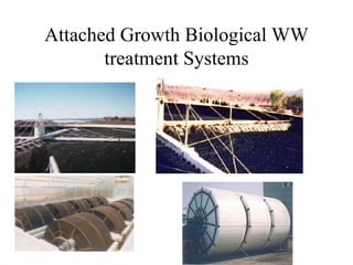
- 1. Attached Growth Biological WW treatment Systems
- 2. Biofilm Systems • Biofilm – a biological slime layer – bacteria in biofilm degrade organics – biofilm will develop on almost anything
- 3. Types of Biofilm Systems • Trickling filters • Rotating biological contactors • Fluidized bed reactors • Biofilters • Wetlands systems • Sequencing batch biofilm reactors (many of these can be aerobic or anaerobic)
- 5. Flow Diagram for Trickling Filters Recycle Primary clarifier Trickling filter Final clarifier Waste sludge Final effluent Influent
- 6. Trickling Filters • Not a true filtering or sieving process • Material only provides surface on which bacteria to grow • Can use plastic media – lighter - can get deeper beds (up to 12 m) – reduced space requirement – larger surface area for growth – greater void ratios (better air flow) – less prone to plugging by accumulating slime
- 9. Typical Modular and Random Packed Plastic Media Schematic diagrams of modular and random packed media used in fixed-film treatment systems (Source: Bordacs and Young, 1998)
- 12. Bio-towers
- 13. Trickling Filter • Tank is filled with solid media – Rocks – Plastic • Bacteria grow on surface of media • Wastewater is trickled over media, at top of tank • As water trickles through media, bacteria degrade BOD • Bacteria eventually die, fall off of media surface • Filter is open to atmosphere, air flows naturally through media • Treated water leaves bottom of tank, flows into secondary clarifier • Bacterial cells settle, removed from clarifier as sludge • Some water is recycled to the filter, to maintain moist conditions
- 16. Bacteria Removal
- 17. Types of Trickling Filters • Standard or low rate – single stage rock media units – loading rates of 1-4 m3 wastewater/m2 filter cross-sectional area-day – large area required
- 18. Types of Trickling Filters • High rate – single stage or two-stage rock media units – loading rates of 10-40 m3 wastewater/m2 filter cross-sectional area-day – re-circulation ratio 1-3
- 19. Types of Trickling Filters • Super rate – synthetic plastic media units • modules or random packed • specific surface areas 2-5 times greater than rock • much lighter than rocks • can be stacked higher than rocks – loading rates of 40-200 m3 wastewater/m2 filter cross-sectional area-day – plastic media depths of 5-10 m
- 20. Design Criteria for Trickling Filters Table 10.5 Typical Design Criteria for Trickling Filters Item Low-rate filter High-rate filter Super-rate filter Hydraulic loading (m3/m2-d) 1 - 4 10 - 40 40 - 200 Organic loading (kg BOD5/m3-d) 0.08 - 0.32 0.32 - 1.0 0.8 - 6.0 Depth (m) 1.5 - 3.0 1.0 - 2.0 4.5 - 12.0 Recirculation ratio 0 1 - 3 1 - 4 Filter media Rock, slag, etc. Rock, slag, synthetics Filter flies Many Few, larvae are washed away Few or none Sloughing Intermittent Continuous Continuous Dosing intervals < 5 min < 15 s Continuous Effluent Usually fully nitrified Nitrified at low loadings Nitrified at low loadings