Download to read offline


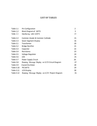

This document summarizes a 4-week industrial training report submitted by a student. It includes sections on interfacing PIC microcontrollers with components like LEDs, seven-segment displays, and LCDs. It also describes a project to display a running message on an LCD using a PIC microcontroller and the necessary power supply circuit. Tables and figures are provided to explain the components, programming, and circuit diagram of the project.


