SlideShare a Scribd company logo
1 of 9
66” ID PRODUCT TANK-FLARE 99


Saddle and Tank stress calculations


Load Cases

The vessel and sub-frame are analyzed under the following conditions:

   Load Case 1: hydro-test 975 psi internal pressure filled with water.

   Load Case 2: storage vessel design pressure 750 psi with 50% filled water.

   Load Case 3: empty vessel mounted on trailer running on road with 0.35g vertical
   and longitudinal reactions combined with 0.2g lateral reaction


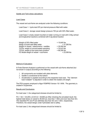
   Weight of 50% filled water                            = 15,645 lbs
   Weigh of hydro-test filled water                             = 31,290 lbs
   Weight of vessel + attachments + saddles              = 35,000 lbs
   TOTAL weight of normal loaded operating               = 50,645 lbs
   TOTAL weight of the hydro-test condition              = 66,290 lbs
   FE Model weight of vessel + sub-frame                        = 23,599 lbs


Method of Calculation

A Finite Element Analysis is performed on the vessel with sub-frame attached (but
not shown in output) according to the following:

   1. All components are modeled with plate elements.
   2. Saddle is constrained at the bottom
   3. Acceleration is applied according to the respective load case. The “element
       load multiplier” is adjusted in order to obtain the loaded unit weight.

The FEA program employed is Algor FEMPRO Version 18.1-WIN. The geometry is
created in Superdraw.

Results and Conclusions

For load case 1, the categorized stresses should be limited to:

Pm < Sm = 34,200 x (3.5/3.0) = 39,900 psi After checking the simulated result, the
highest total stress on vessel is 39,024 psi, less than 1.5Sm and even less than Sm.
The classified Pm and Pl are definitely less than Sm and 1.5Sm, respectively.
Therefore, the vessel design under hydrostatic test is safety.

For load case 2, the categorized stresses should be limited to


                                                                                       1 OF 9
66” ID PRODUCT TANK-FLARE 99


Pm < Sm = 23,300 psi
Pl < 1.5 Sm = 35,000 psi
Pl + Pb < 1.5 Sm = 35,000 psi

where Sm is the allowable general membrane stress, 70,000/3.0 = 23,300 psi.


After checking all the images, the maximum valve of Pm on vessel is 19,993 psi, the
maximum value of Pl + Pb on vessel is 30,017 psi. Therefore, the all above criteria is
satisfied and the vessel design is safety.

For load case 3, the code of CSA B620-03 must be satisfied. According to B620-03,
the allowable stress is based on the ultimate strength of material by using safety
factor 4. Therefore, the allowable general membrane stress Sm = 70,000/4.0 =
17,500 psi. From the simulated result, stresses on vessel are much less than the
allowable general membrane stress 17,500 psi defined in B620-03. The vessel
design to B620-03 is safety.

The saddle is made from SA-516-70, the yield strength is 38,000 psi. In all the above
load cases, the maximum value of stresses in Von Mises is 19,801 psi and safety
enough to withstand static and dynamic loads.


                                                                                         2 OF 9
3 OF 9
4 OF 9
5 OF 9
6 OF 9
7 OF 9
8 OF 9
9 OF 9

More Related Content

What's hot

solution-manual-3rd-ed-metal-forming-mechanics-and-metallurgy-chapter-1-3
 solution-manual-3rd-ed-metal-forming-mechanics-and-metallurgy-chapter-1-3 solution-manual-3rd-ed-metal-forming-mechanics-and-metallurgy-chapter-1-3
solution-manual-3rd-ed-metal-forming-mechanics-and-metallurgy-chapter-1-3
dean129
 
Design by Analysis - A general guideline for pressure vessel
Design by Analysis - A general guideline for pressure vesselDesign by Analysis - A general guideline for pressure vessel
Design by Analysis - A general guideline for pressure vessel
AnalyzeForSafety
 

What's hot (20)

Sample problemsstatics
Sample problemsstaticsSample problemsstatics
Sample problemsstatics
 
Base ring analysis
Base ring analysisBase ring analysis
Base ring analysis
 
Hw ch7
Hw ch7Hw ch7
Hw ch7
 
Parts of shell and tube heat exchanger
Parts of shell and tube heat exchangerParts of shell and tube heat exchanger
Parts of shell and tube heat exchanger
 
Fox solution
Fox   solutionFox   solution
Fox solution
 
solution-manual-3rd-ed-metal-forming-mechanics-and-metallurgy-chapter-1-3
 solution-manual-3rd-ed-metal-forming-mechanics-and-metallurgy-chapter-1-3 solution-manual-3rd-ed-metal-forming-mechanics-and-metallurgy-chapter-1-3
solution-manual-3rd-ed-metal-forming-mechanics-and-metallurgy-chapter-1-3
 
Heat Exchanger
Heat ExchangerHeat Exchanger
Heat Exchanger
 
Cooling tower calculation (1) (1)
Cooling tower calculation (1) (1)Cooling tower calculation (1) (1)
Cooling tower calculation (1) (1)
 
Tutorial #4 - SACS Basic
Tutorial #4 - SACS BasicTutorial #4 - SACS Basic
Tutorial #4 - SACS Basic
 
Tutorial # 3 +solution
Tutorial # 3  +solution Tutorial # 3  +solution
Tutorial # 3 +solution
 
Heat transfer 5th ed incropera solution manual
Heat transfer 5th ed incropera solution manualHeat transfer 5th ed incropera solution manual
Heat transfer 5th ed incropera solution manual
 
Wave force
Wave forceWave force
Wave force
 
Design of Ice Manufacturing Plant 2000 lb
Design of Ice Manufacturing Plant 2000 lbDesign of Ice Manufacturing Plant 2000 lb
Design of Ice Manufacturing Plant 2000 lb
 
Design by Analysis - A general guideline for pressure vessel
Design by Analysis - A general guideline for pressure vesselDesign by Analysis - A general guideline for pressure vessel
Design by Analysis - A general guideline for pressure vessel
 
Lecture 8_MDPE_Design of Nozzles & Flange.pdf
Lecture 8_MDPE_Design of Nozzles & Flange.pdfLecture 8_MDPE_Design of Nozzles & Flange.pdf
Lecture 8_MDPE_Design of Nozzles & Flange.pdf
 
Design of pressure vessel
Design of pressure vesselDesign of pressure vessel
Design of pressure vessel
 
Gas Plant Separator Design
Gas Plant Separator DesignGas Plant Separator Design
Gas Plant Separator Design
 
HTRI PRESENTATION.pdf
HTRI PRESENTATION.pdfHTRI PRESENTATION.pdf
HTRI PRESENTATION.pdf
 
Superheated vs saturated Steam - chemical plants
Superheated vs saturated Steam - chemical plantsSuperheated vs saturated Steam - chemical plants
Superheated vs saturated Steam - chemical plants
 
Andritz
AndritzAndritz
Andritz
 

Viewers also liked (7)

Horizontal Vessel Loading Calculation
 Horizontal Vessel Loading Calculation Horizontal Vessel Loading Calculation
Horizontal Vessel Loading Calculation
 
Vertical vessel loading calculation
Vertical vessel loading calculationVertical vessel loading calculation
Vertical vessel loading calculation
 
PRESSURE VESSEL NEW-GENERAL ARRANGEMENT
PRESSURE VESSEL NEW-GENERAL ARRANGEMENTPRESSURE VESSEL NEW-GENERAL ARRANGEMENT
PRESSURE VESSEL NEW-GENERAL ARRANGEMENT
 
Pvp2005 71123
Pvp2005 71123Pvp2005 71123
Pvp2005 71123
 
Bs 2594 specification for carbon steel welded horizontal cylindrical storage ...
Bs 2594 specification for carbon steel welded horizontal cylindrical storage ...Bs 2594 specification for carbon steel welded horizontal cylindrical storage ...
Bs 2594 specification for carbon steel welded horizontal cylindrical storage ...
 
BE Chemical Engineering Design Project Production Of Propylene Oxide
BE Chemical Engineering Design Project   Production Of Propylene OxideBE Chemical Engineering Design Project   Production Of Propylene Oxide
BE Chemical Engineering Design Project Production Of Propylene Oxide
 
ProjectReportL&T
ProjectReportL&TProjectReportL&T
ProjectReportL&T
 

Similar to Vessel And Saddle Cal

3 Fire Tube Fea Calculation Viii Div2 Ra
3 Fire Tube Fea Calculation Viii Div2 Ra3 Fire Tube Fea Calculation Viii Div2 Ra
3 Fire Tube Fea Calculation Viii Div2 Ra
wangzh2k
 
Callum Pickard - DC White Portfolio
Callum Pickard - DC White PortfolioCallum Pickard - DC White Portfolio
Callum Pickard - DC White Portfolio
Callum Pickard
 
FINAL Hyperloop Structure Analysis- Pylon,Columns,and Carriage
FINAL Hyperloop Structure Analysis- Pylon,Columns,and CarriageFINAL Hyperloop Structure Analysis- Pylon,Columns,and Carriage
FINAL Hyperloop Structure Analysis- Pylon,Columns,and Carriage
naman gupta
 
METHOD AND ASSESSMENT FOR LOAD TEST.ppt
METHOD AND ASSESSMENT FOR LOAD TEST.pptMETHOD AND ASSESSMENT FOR LOAD TEST.ppt
METHOD AND ASSESSMENT FOR LOAD TEST.ppt
ShaheedAzhar
 
0264 GustoMSC_PowerPointTemplate_08_2010[1].PPT
0264 GustoMSC_PowerPointTemplate_08_2010[1].PPT0264 GustoMSC_PowerPointTemplate_08_2010[1].PPT
0264 GustoMSC_PowerPointTemplate_08_2010[1].PPT
Arie van Dijken
 
Mini Project - STRUCTURAL-ANALYSIS-AND-MATERIAL-SELECTION
Mini Project - STRUCTURAL-ANALYSIS-AND-MATERIAL-SELECTIONMini Project - STRUCTURAL-ANALYSIS-AND-MATERIAL-SELECTION
Mini Project - STRUCTURAL-ANALYSIS-AND-MATERIAL-SELECTION
dna1992
 

Similar to Vessel And Saddle Cal (20)

3 Fire Tube Fea Calculation Viii Div2 Ra
3 Fire Tube Fea Calculation Viii Div2 Ra3 Fire Tube Fea Calculation Viii Div2 Ra
3 Fire Tube Fea Calculation Viii Div2 Ra
 
Analysis of Catalyst Support Ring in a pressure vessel based on ASME Section ...
Analysis of Catalyst Support Ring in a pressure vessel based on ASME Section ...Analysis of Catalyst Support Ring in a pressure vessel based on ASME Section ...
Analysis of Catalyst Support Ring in a pressure vessel based on ASME Section ...
 
Analysis of Modeled Composite Diving Board
Analysis of Modeled Composite Diving BoardAnalysis of Modeled Composite Diving Board
Analysis of Modeled Composite Diving Board
 
Drilling Mannual
Drilling MannualDrilling Mannual
Drilling Mannual
 
Callum Pickard - DC White Portfolio
Callum Pickard - DC White PortfolioCallum Pickard - DC White Portfolio
Callum Pickard - DC White Portfolio
 
Qualification under hypothetical accident conditions during transport-R Pal
Qualification under hypothetical accident conditions during transport-R PalQualification under hypothetical accident conditions during transport-R Pal
Qualification under hypothetical accident conditions during transport-R Pal
 
2- OHL components - Part 3 - Sagaaaa.pdf
2- OHL components - Part 3 - Sagaaaa.pdf2- OHL components - Part 3 - Sagaaaa.pdf
2- OHL components - Part 3 - Sagaaaa.pdf
 
FINAL Hyperloop Structure Analysis- Pylon,Columns,and Carriage
FINAL Hyperloop Structure Analysis- Pylon,Columns,and CarriageFINAL Hyperloop Structure Analysis- Pylon,Columns,and Carriage
FINAL Hyperloop Structure Analysis- Pylon,Columns,and Carriage
 
Aircraft design lab report converted
Aircraft design lab report convertedAircraft design lab report converted
Aircraft design lab report converted
 
Reliability of Flip-Chip Packages
Reliability of Flip-Chip PackagesReliability of Flip-Chip Packages
Reliability of Flip-Chip Packages
 
Jacketed vessel design
Jacketed vessel designJacketed vessel design
Jacketed vessel design
 
Extreme HPHT package development
Extreme HPHT package developmentExtreme HPHT package development
Extreme HPHT package development
 
METHOD AND ASSESSMENT FOR LOAD TEST.ppt
METHOD AND ASSESSMENT FOR LOAD TEST.pptMETHOD AND ASSESSMENT FOR LOAD TEST.ppt
METHOD AND ASSESSMENT FOR LOAD TEST.ppt
 
Buckling Analysis of a simple rail
Buckling Analysis of a simple railBuckling Analysis of a simple rail
Buckling Analysis of a simple rail
 
Finite Element Analysis of Skirt to Dished junction in a Pressure Vessel
Finite Element Analysis of Skirt to Dished junction in a Pressure VesselFinite Element Analysis of Skirt to Dished junction in a Pressure Vessel
Finite Element Analysis of Skirt to Dished junction in a Pressure Vessel
 
INTACT STABILITY BOOKLET
INTACT STABILITY BOOKLET INTACT STABILITY BOOKLET
INTACT STABILITY BOOKLET
 
0264 GustoMSC_PowerPointTemplate_08_2010[1].PPT
0264 GustoMSC_PowerPointTemplate_08_2010[1].PPT0264 GustoMSC_PowerPointTemplate_08_2010[1].PPT
0264 GustoMSC_PowerPointTemplate_08_2010[1].PPT
 
Mini Project - STRUCTURAL-ANALYSIS-AND-MATERIAL-SELECTION
Mini Project - STRUCTURAL-ANALYSIS-AND-MATERIAL-SELECTIONMini Project - STRUCTURAL-ANALYSIS-AND-MATERIAL-SELECTION
Mini Project - STRUCTURAL-ANALYSIS-AND-MATERIAL-SELECTION
 
World One Towers, Mumbai
World One Towers, MumbaiWorld One Towers, Mumbai
World One Towers, Mumbai
 
Design of Composite Pressure Vessel
Design of Composite Pressure VesselDesign of Composite Pressure Vessel
Design of Composite Pressure Vessel
 

Vessel And Saddle Cal

  • 1. 66” ID PRODUCT TANK-FLARE 99 Saddle and Tank stress calculations Load Cases The vessel and sub-frame are analyzed under the following conditions: Load Case 1: hydro-test 975 psi internal pressure filled with water. Load Case 2: storage vessel design pressure 750 psi with 50% filled water. Load Case 3: empty vessel mounted on trailer running on road with 0.35g vertical and longitudinal reactions combined with 0.2g lateral reaction Weight of 50% filled water = 15,645 lbs Weigh of hydro-test filled water = 31,290 lbs Weight of vessel + attachments + saddles = 35,000 lbs TOTAL weight of normal loaded operating = 50,645 lbs TOTAL weight of the hydro-test condition = 66,290 lbs FE Model weight of vessel + sub-frame = 23,599 lbs Method of Calculation A Finite Element Analysis is performed on the vessel with sub-frame attached (but not shown in output) according to the following: 1. All components are modeled with plate elements. 2. Saddle is constrained at the bottom 3. Acceleration is applied according to the respective load case. The “element load multiplier” is adjusted in order to obtain the loaded unit weight. The FEA program employed is Algor FEMPRO Version 18.1-WIN. The geometry is created in Superdraw. Results and Conclusions For load case 1, the categorized stresses should be limited to: Pm < Sm = 34,200 x (3.5/3.0) = 39,900 psi After checking the simulated result, the highest total stress on vessel is 39,024 psi, less than 1.5Sm and even less than Sm. The classified Pm and Pl are definitely less than Sm and 1.5Sm, respectively. Therefore, the vessel design under hydrostatic test is safety. For load case 2, the categorized stresses should be limited to 1 OF 9
  • 2. 66” ID PRODUCT TANK-FLARE 99 Pm < Sm = 23,300 psi Pl < 1.5 Sm = 35,000 psi Pl + Pb < 1.5 Sm = 35,000 psi where Sm is the allowable general membrane stress, 70,000/3.0 = 23,300 psi. After checking all the images, the maximum valve of Pm on vessel is 19,993 psi, the maximum value of Pl + Pb on vessel is 30,017 psi. Therefore, the all above criteria is satisfied and the vessel design is safety. For load case 3, the code of CSA B620-03 must be satisfied. According to B620-03, the allowable stress is based on the ultimate strength of material by using safety factor 4. Therefore, the allowable general membrane stress Sm = 70,000/4.0 = 17,500 psi. From the simulated result, stresses on vessel are much less than the allowable general membrane stress 17,500 psi defined in B620-03. The vessel design to B620-03 is safety. The saddle is made from SA-516-70, the yield strength is 38,000 psi. In all the above load cases, the maximum value of stresses in Von Mises is 19,801 psi and safety enough to withstand static and dynamic loads. 2 OF 9