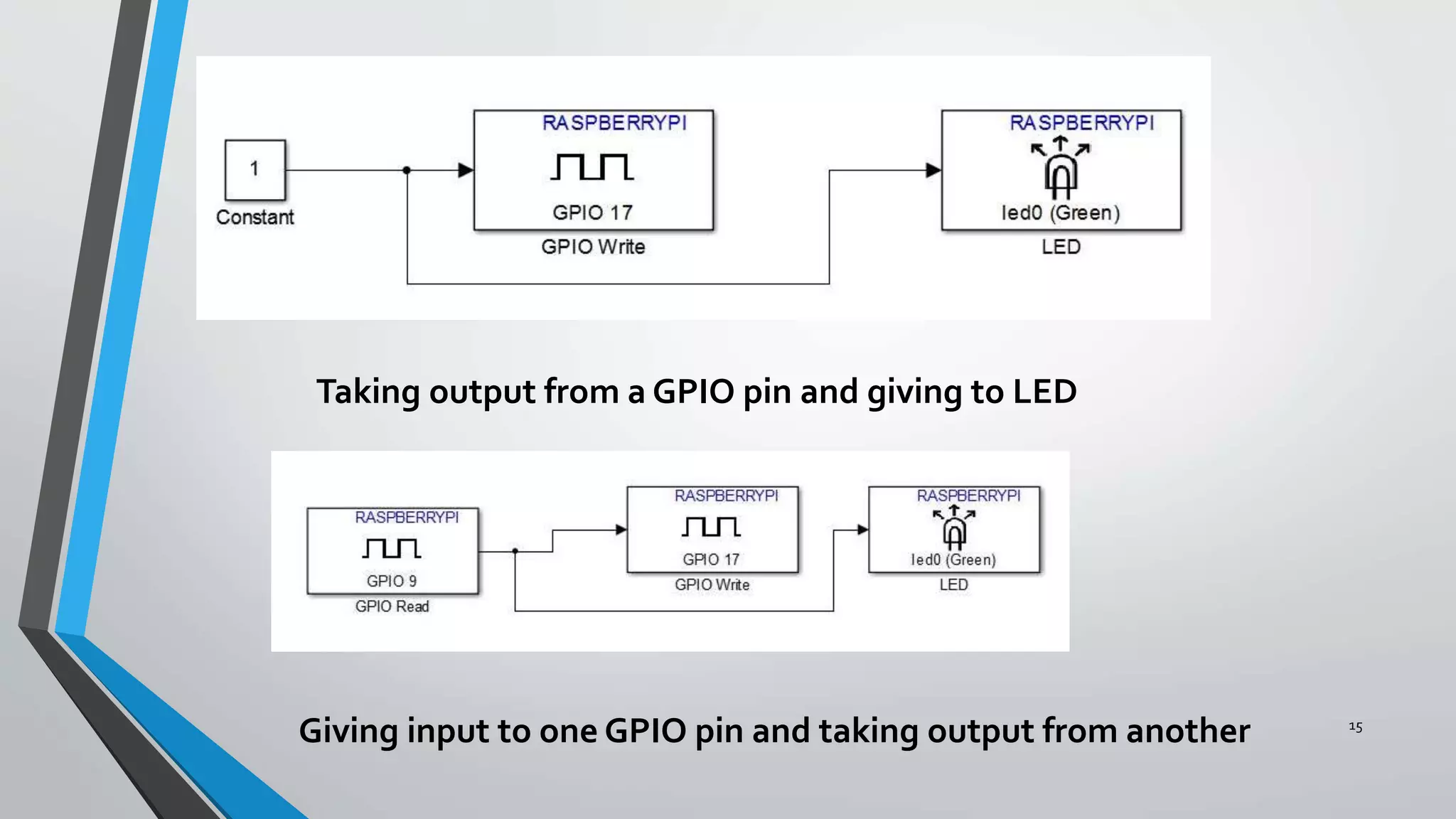
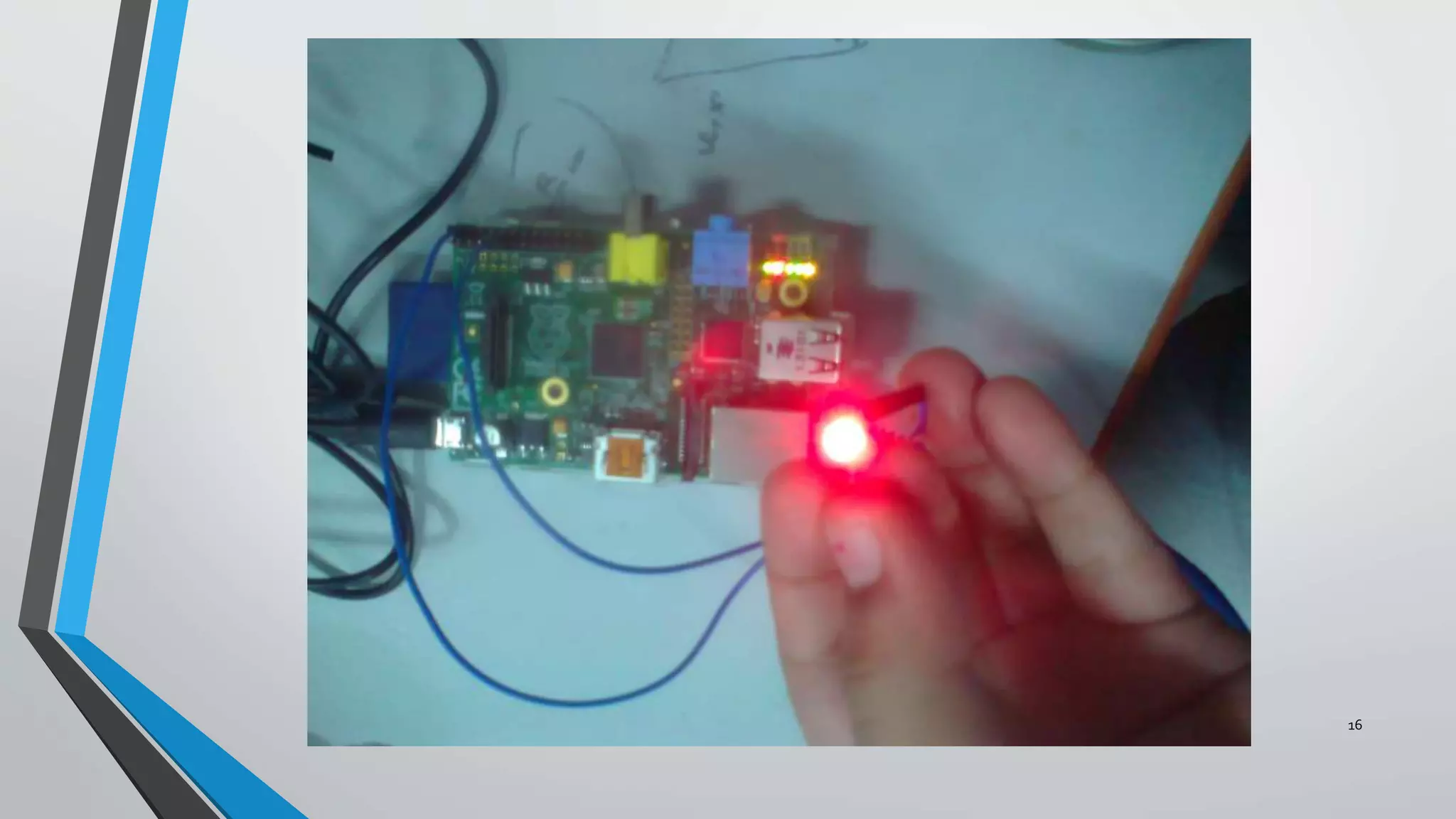
MACHINETO MACHINE
COMMUNICATION DEVICE
DEVELOPMENT FOR MEDICAL
APPLICATIONS AND DISASTER
MANAGEMENT
Dikshya Shree Rath
Department of Electronics and Communication
National Institute of Technology, Rourkela
OVERVIEW
2
• Literature Survey
• Introduction to M2M :
 What is M2M?
Why M2M?
Concerns and issues of M2M
M2M architecture
Applications
• Software used and System Requirements
• Hardware used
• Proposal
• Implementation till now
• Block Diagrams and Results
LITERATURE SURVEY
3
• DavidJ. Foran and Laura A. Goodell and Robert L.Trelstad,” A Distributed System for Medical
consultation and Education” Member, IEEE May 1, 2004
• Luca Bedogni,AngeloTrotta, Marco Di Felice, Luciano Bononi , ”Machine-to-Machine
Communication overTV White Spaces for Smart Metering Applications” , Department of
Computer Science and Engineering, University of Bologna
• Gil-Yong Lee,1 Nam-YeolYun,1 Sung-Chul Lee,2 and Soo-Hyun Park “A Smart ElectronicTagging
System Based on Context awareness and Machine-to-Machine Interworking“Accepted 9 August
2013(Research article)
• Kwang-ChengChen , Shao-Yu Lien “Machine-to-machine communications:Technologies and
challenges” 16th march 2013
• White Paper on "Machine-to-Machine Communication (M2M)”
What Is M2M?
Machine to Machine (M2M) refers to technologies that allow both
wireless and wired systems to communicate with other devices of
the same type.
M2M uses a device (sensor, meter, etc.) to capture an ‘event’
(temperature, inventory level, etc.), which is relayed through a
network (wireless, wired or hybrid) to an application (software
program), that translates the captured event into meaningful
information
4
WHY M2M??
5
• Stay connected with your technical devices and
systems
• Remote management, monitoring and
notification capabilities
• Automate and optimize processes
• Monitor present conditions
• Identify critical situations
6
• The M2M System should be flexible in
supporting more than one naming scheme.
• Dealing with increased security threats and
vulnerability.
• Expenses need to be minimized.
• Maintenance and continuous monitoring.
CONCERNS AND ISSUES OF M2M
M2M ARCHITECTURE
7
APPLICATIONS
8
• Security
• Tracking &Tracing
• Payment
• Health
• Remote Maintenance/Control
• Metering
• Manufacturing
• Facility Management
9
SOFTWARE USED
SIMULINK R2013B
Simulink developed by MathWorks is a dataflow graphical programming
language tool for modelling, simulating and analyzing multidomain dynamic
systems.
SYSTEM REQUIREMENTS
• MATLAB R2013b installed with the Simulink support packages for Raspberry Pi
downloaded and configured
• Raspberry Pi with the OS (Raspbian wheezy) booted in the SD card
• Ethernet cable and Micro SD card.
10
HARDWARE USED
RASPBERRY PI
Raspberry PI is a credit card sized single board computer developed by
Raspberry PI Foundation, UK
Features:-
• 700MHz Processor
• 256 Mb RAM
• Level 2 Cache is 128Kb
• Ethernet port available
• 2 USB ports
• HDMI port
11
12
PROPOSAL:MODEL AND APPLICATION
13
• To design a Machine to Machine device that will take data from the
pulse/heart rate or temperature of a human being measured and sent to one
monitoring device via LAN as digital data and the samples will be analysed for
a threshold level .
• If it exceeds it then person will not be allowed to drive the vehicle for these
results will be compared with the parameters of a human body after alcohol
consumption.This incorporates medical and disaster applications both.
• The data can be sent to medical professionals at the back end and the person
can be warned of the health hazards as well as incorporating this will regulate
and reduce the number of road accidents that take place due to reckless and
drunk driving .
14
IMPLEMENTATIONTILL NOW
• Installation of support packages for Raspberry Pi in Simulink.
• Configuring the Raspberry Pi to the Electronics Department Internet Network.
• Running the image inversion algorithm in Raspberry Pi. Captured the image on my
laptop, connected USB webcam on Raspberry Pi and sent the image to this cam
via Simulink model and LAN.
• Took output from the GPIO (General purpose Input output) pins and
checked the voltage and glowed a LED
• Gave input to the GPIO pins via a button and tried to check the output of
another pin
15
Taking output from a GPIO pin and giving to LED
Giving input to one GPIO pin and taking output from another
16
17
This video shows how the Raspberry Pi and my laptop were communicating after the
Simulink Model was dumped.The devices were connected via LAN of the Electronics
Department.The board gave an inverse logic as the LED glowed when the switch
was released.
THANKYOU !!!!
18

Final yr proj ppt

  • 1.
    MACHINETO MACHINE COMMUNICATION DEVICE DEVELOPMENTFOR MEDICAL APPLICATIONS AND DISASTER MANAGEMENT Dikshya Shree Rath Department of Electronics and Communication National Institute of Technology, Rourkela
  • 2.
    OVERVIEW 2 • Literature Survey •Introduction to M2M :  What is M2M? Why M2M? Concerns and issues of M2M M2M architecture Applications • Software used and System Requirements • Hardware used • Proposal • Implementation till now • Block Diagrams and Results
  • 3.
    LITERATURE SURVEY 3 • DavidJ.Foran and Laura A. Goodell and Robert L.Trelstad,” A Distributed System for Medical consultation and Education” Member, IEEE May 1, 2004 • Luca Bedogni,AngeloTrotta, Marco Di Felice, Luciano Bononi , ”Machine-to-Machine Communication overTV White Spaces for Smart Metering Applications” , Department of Computer Science and Engineering, University of Bologna • Gil-Yong Lee,1 Nam-YeolYun,1 Sung-Chul Lee,2 and Soo-Hyun Park “A Smart ElectronicTagging System Based on Context awareness and Machine-to-Machine Interworking“Accepted 9 August 2013(Research article) • Kwang-ChengChen , Shao-Yu Lien “Machine-to-machine communications:Technologies and challenges” 16th march 2013 • White Paper on "Machine-to-Machine Communication (M2M)”
  • 4.
    What Is M2M? Machineto Machine (M2M) refers to technologies that allow both wireless and wired systems to communicate with other devices of the same type. M2M uses a device (sensor, meter, etc.) to capture an ‘event’ (temperature, inventory level, etc.), which is relayed through a network (wireless, wired or hybrid) to an application (software program), that translates the captured event into meaningful information 4
  • 5.
    WHY M2M?? 5 • Stayconnected with your technical devices and systems • Remote management, monitoring and notification capabilities • Automate and optimize processes • Monitor present conditions • Identify critical situations
  • 6.
    6 • The M2MSystem should be flexible in supporting more than one naming scheme. • Dealing with increased security threats and vulnerability. • Expenses need to be minimized. • Maintenance and continuous monitoring. CONCERNS AND ISSUES OF M2M
  • 7.
  • 8.
    APPLICATIONS 8 • Security • Tracking&Tracing • Payment • Health • Remote Maintenance/Control • Metering • Manufacturing • Facility Management
  • 9.
    9 SOFTWARE USED SIMULINK R2013B Simulinkdeveloped by MathWorks is a dataflow graphical programming language tool for modelling, simulating and analyzing multidomain dynamic systems. SYSTEM REQUIREMENTS • MATLAB R2013b installed with the Simulink support packages for Raspberry Pi downloaded and configured • Raspberry Pi with the OS (Raspbian wheezy) booted in the SD card • Ethernet cable and Micro SD card.
  • 10.
    10 HARDWARE USED RASPBERRY PI RaspberryPI is a credit card sized single board computer developed by Raspberry PI Foundation, UK Features:- • 700MHz Processor • 256 Mb RAM • Level 2 Cache is 128Kb • Ethernet port available • 2 USB ports • HDMI port
  • 11.
  • 12.
  • 13.
    PROPOSAL:MODEL AND APPLICATION 13 •To design a Machine to Machine device that will take data from the pulse/heart rate or temperature of a human being measured and sent to one monitoring device via LAN as digital data and the samples will be analysed for a threshold level . • If it exceeds it then person will not be allowed to drive the vehicle for these results will be compared with the parameters of a human body after alcohol consumption.This incorporates medical and disaster applications both. • The data can be sent to medical professionals at the back end and the person can be warned of the health hazards as well as incorporating this will regulate and reduce the number of road accidents that take place due to reckless and drunk driving .
  • 14.
    14 IMPLEMENTATIONTILL NOW • Installationof support packages for Raspberry Pi in Simulink. • Configuring the Raspberry Pi to the Electronics Department Internet Network. • Running the image inversion algorithm in Raspberry Pi. Captured the image on my laptop, connected USB webcam on Raspberry Pi and sent the image to this cam via Simulink model and LAN. • Took output from the GPIO (General purpose Input output) pins and checked the voltage and glowed a LED • Gave input to the GPIO pins via a button and tried to check the output of another pin
  • 15.
    15 Taking output froma GPIO pin and giving to LED Giving input to one GPIO pin and taking output from another
  • 16.
  • 17.
    17 This video showshow the Raspberry Pi and my laptop were communicating after the Simulink Model was dumped.The devices were connected via LAN of the Electronics Department.The board gave an inverse logic as the LED glowed when the switch was released.
  • 18.