1. ®
CADISON Electric-Designer
CADISON® Electric-Designer
(Integrated Designer Module)
The CADISON® Electric-Designer combines planning efforts
with process control engineering. PLT points (measuring
points) defined by the process engineer are further detailed
by CADISON® Electric-Designer with the required
instrumentation. The electrical planning engineers base their
work on the specified media data and connection parameters
delivered by the process engineer.
Key Features
?
Integrated and Intelligent database Electrical 2D
schematic, 3D model system.
?
Automatic creation of Terminal Drawings and contact sets
(automatic adjustment of pin numbers, etc).
Facility Management
Electric-Designer is used both for electrical planning of a
plant in classical plant engineering and even for facility
management. For example, this module is used for document
creation for operation management of complex line
networks.
Typical
Pre-fabricated typicals are used for automatic graphic
generation and presentation of instrumentation in the
measuring-point chart. The planning engineer may use prefabricated ‘Typical’. It is easy to extend the ‘Typical’ to suit
project need.
?
Numbering and identification system according to DIN
and KKS. Automatic Device Tagging and Wire numbering.
Loop Wiring Diagrams
?
Configurable Logic Analyzer for error checking.
?
Predefined measuring point structure in form of ‘Typical’.
?
Real-time coil and contacts cross-referencing.
?
Reference / Assign ‘Typical’ to a measuring point.
?
Automatic connection of wiring between components.
?
Easy creation and updating of Measuring Point ‘Typical’.
?
Customizable object designation (Text Mask).
? Drop to create automatic loop wiring diagram.
Drag and
?
Auto generation of Legend, Notes and Abbreviation.
? quick cross referencing of components
Easy and
represented in different drawings. (Devices with
distributed representation - Relay contacts, Terminals etc).
?
Automatic and customizable reports generation.
? revision management for reports and drawings.
Project
?
ETAP interface for SLD’s which reduces the need for
manual entries by 50%.
3D cable tray and bus duct routing & 3D Panel layout
drawings
?
Availability of 3D E&I Equipments, Meters, Panels, Ducts
enable creation of Layouts linked with 3D Model, clash
detection.
?
Automatic Cable Routing, Extendable Cable tray library to
handle complex routing.
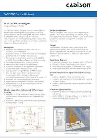
Circuit Diagram
Devices with distributed representation (relay-contact
set)
? calculation of free and used contacts.
Runtime
?
Intelligent and easy selection functionality while inserting
contact in drawing.
? contact blocks for augmenting capacity of relay /
Auxiliary
contactor.
Automatic Legend Creation
?
Possibility to choose the property to be displayed along
with symbol.
? to filter or limit type of objects to be displayed in
Facility
legend with help of configuration file.
3D Installation Layout
2. Automatic Device Tagging and Wire Numbering
? possibilities for auto numbering of wires and
Multiple
devices.
? number assignment at the time of creation.
Dynamic
?
Renumbering will reassign the number based on level of
selection, position of devices with in drawing. Provision for
renumbering at drawing, logical plant, location and project
levels.
Automatic Terminal Drawing
?
Automatic terminal drawing feature to create new
Terminal Strip Editor
Terminal Drawing.
? drop feature to create multiple terminal
Drag and
diagrams in a single sheet.
? strip editor- to rearrange terminals, reTerminal
numbering of terminals in GUI.
?
Configure graphical representation parameters at project
level.
? sensitive menu for creation as well as updating of
Context
existing drawing.
PLC Configurator
? the work of electric planning engineer for
Supports
management of input and output signals.
? flow can be presented in one function diagram
Process
with all signals.
Single Line Diagram
2D GA and Hookup Drawings
?
Extraction of 2D layout drawings from 3D model.
?
Tabulated list with predefined ‘Typical’ (image) for design
process clarity.
? to create ‘Typical’ mounting details suit to project
Provision
needs.
?
Automatic creation of hookup drawing for instrument
installation too.
?
Configurable drawing templates, ‘Typical’ and hookup
parameters.
?/ link multiple process measuring points to a single
Assign
hookup.
2D GA of Cabinet / Panels
ETAP Interface
To export Single Line Diagrams to ETAP though data
exchange excel format.
Report Generator
? generate reports at Project, Drawing and Object
Ability to
level.
?
Configurable reports for list of Input / Output electrical
and automation components.
?
Considerable numbers of predefined report formats are
available with standard installer.
? MS Word, Excel & PDF, generate multilingual
Supports
reports (English, German).
Customizable Symbols and Catalogs
www.cadison.com