SlideShare a Scribd company logo
1 of 65
Download to read offline
Resulting
tilting
moment
(kNm)
Axial load (kN)
Static boundary load curves Race – – – Bolts 10.9
Bearing without
gearing
Geometry Attachment
Drawing number
Ø DL
mm
Ø Da
mm
Ø Di
mm
H
mm
Ø O
mm
Ø U
mm
Ø La
mm
na
Ø B
mm
Ø Li
mm
ni
Ø B
mm
1 250.14.0300.013
Type 13/400 Unhardened
race
323 401 233 40 348 298 380 8 14 260 8 14
2 250.14.0400.013
Type 13/500
421 501 333 40 446 396 480 8 14 360 8 14
3 250.15.0300.013
Type 13/400 Hardened
race
323 401 233 40 348 298 380 8 14 260 8 14
4 250.15.0400.013
Type 13/500
421 501 333 40 446 396 480 8 14 360 8 14
Miscellaneous
kg
n1
Y axial
mm
Y radial
mm
9,6 4 ≤ 0,5 ≤ 0,5
13,1 4 ≤ 0,5 ≤ 0,5
9,6 4 ≤ 0,5 ≤ 0,5
13,1 4 ≤ 0,5 ≤ 0,5
H
ø Li
√
√
ø La
ø DL
ø Di*
√
√
ø B
ø Da*
n1
7
,5
7
ø B
≈ ø U
≈ ø O
Series 25, 23, 28 profile bearing
Standard Series type 13, Normal bearing
If centering spigots
are required for
normal bearings,
these must be
specified when the
order is placed.
Centering spigots
are only possible if
* is indicated for the
nominal diameter.
For loads above
the bolt boundary
load curve with
raceway boundary
load curve 4 the
number of fastening
bolts must be
doubled.
Diameter tolerances
Machined diameters with untoleranced
drawing dimensions have the following
tolerances:
≤ 315mm ± 1,6mm
≤ 1000mm ± 2,5mm
n1
= Tapered grease nipple
H 1a - 6 mm Ø
≈ evenly distributed
√ = √
rolled
Dimensions of these
centering spigots: outside inside
Type 13/400 ... 13/500 − 0,5 mm + 0,5 mm
Bearing
selection series
25, 23, 28
Please contact me if need slewing bearings.
Email:wenchen@allslewingbearing.com
Whatsapp&wechat:+8617702586093
https://www.allslewingbearing.com
Please contact me if need slewing bearings.
Email:wenchen@allslewingbearing.com
Whatsapp&wechat:+8617702586093
https://www.allslewingbearing.com
80 81
Resulting
tilting
moment
(kNm)
Axial load (kN)
Static boundary load curves Race – – – Bolts 10.9
Bearing without
gearing
Geometry Attachment
Drawing number
Ø DL
mm
Ø Da
mm
Ø Di
mm
H
mm
Ø O
mm
Ø U
mm
Ø La
mm
na
Ø B
mm
Ø Li
mm
ni
Ø B
mm
3 250.15.0375.013
Type 13/400 Hardened
race
323
400
− 0,09
234
+ 0,07
40 348 298 380 8 14 260 8 14
4 250.15.0475.013
Type 13/500
421
500
− 0,10
334
+ 0,09
40 446 396 480 8 14 360 8 14
Miscellaneous
kg
n1
Y axial + radial
mm
9,6 4 ≤ 0 to 0,02
13,1 4 ≤ 0 to 0,02
H
ø Li
√
√
ø La
ø DL
ø Di*
√
√
ø B
ø Da*
n1
7
,5
7
ø B
≈ ø U
≈ ø O
Series 25, 23, 28 profile bearing
Standard Series type 13, Normal bearing
Diameter tolerances
Machined diameters with untoleranced
drawing dimensions have the following
tolerances:
≤ 315mm ± 1,6mm
≤ 1000mm ± 2,5mm
n1
= Tapered grease nipple
H 1a - 6 mm Ø
≈ evenly distributed
√ = √
rolled
If centering spigots
are required for
normal bearings,
these must be
specified when the
order is placed.
Centering spigots
are only possible if
* is indicated for the
nominal diameter.
For loads above
the bolt boundary
load curve with
raceway boundary
load curve 4 the
number of fastening
bolts must be
doubled.
Dimensions of these
centering spigots: outside inside
Type 13/400 ... 13/500 − 0,5 mm + 0,5 mm
Bearing
selection series
25, 23, 28
Please contact me if need slewing bearings.
Email:wenchen@allslewingbearing.com
Whatsapp&wechat:+8617702586093
https://www.allslewingbearing.com
Please contact me if need slewing bearings.
Email:wenchen@allslewingbearing.com
Whatsapp&wechat:+8617702586093
https://www.allslewingbearing.com
82 Bearing selection series 25, 23, 28 83
Resulting
tilting
moment
(kNm)
Axial load (kN)
Static boundary load curves Race – – – Bolts 10.9
Bearing without
gearing
Geometry
Drawing number
Ø DL
mm
Ø Da
mm
Ø Di
mm
H
mm
Ø O
mm
Ø U
mm
Ø A
mm
Ø C
mm
Hu
mm
Ho
mm
5 230.20.0400.013
Type 21/520.0
414 518 304 56 412,5 415,5 453 375 10,5 10,5
6 230.20.0500.013
Type 21/650.0
544 648 434 56 542,5 545,5 583 505 10,5 10,5
7 230.20.0600.013
Type 21/750.0
644 748 534 56 642,5 645,5 683 605 10,5 10,5
8 230.20.0700.013
Type 21/850.0
744 848 634 56 742,5 745,5 783 705 10,5 10,5
9 230.20.0800.013
Type 21/950.0
844 948 734 56 842,5 845,5 883 805 10,5 10,5
10 230.20.0900.013
Type 21/1050.0
944 1048 834 56 942,5 945,5 983 905 10,5 10,5
11 230.20.1000.013
Type 21/1200.0
1094 1198 984 56 1092,5 1095,5 1133 1055 10,5 10,5
Attachment Miscellaneous
Ø La
mm
na
Ø B
mm
Ø Li
mm
ni
Ø B
mm kg
n1
Y axial
mm
Y radial
mm
490 8 18 332 12 18 23,4 4 ≤ 0,5 ≤ 0,5
620 10 18 462 14 18 31,0 4 ≤ 0,5 ≤ 0,5
720 12 18 562 16 18 36,4 4 ≤ 0,5 ≤ 0,5
820 12 18 662 16 18 42,8 4 ≤ 0,5 ≤ 0,5
920 14 18 762 18 18 47,8 4 ≤ 0,5 ≤ 0,5
1020 16 18 862 20 18 53,1 4 ≤ 0,5 ≤ 0,5
1170 16 18 1012 20 18 61,9 4 ≤ 0,5 ≤ 0,5
Series 25, 23, 28 profile bearing
Standard Series type 21, Normal bearing, normal number of holes profile ring
Double number of holes see curves 12 – 18, page 88
Diameter tolerances
Machined diameters with untoleranced
drawing dimensions have the following
tolerances:
≤ 315mm ± 1,6mm
≤ 1000mm ± 2,5mm
≤ 2000mm ± 3,5mm
n1
= Tapered grease nipple
AM 8 x 1 DIN 71412
≈ evenly distributed
On request, with non-geared bearings,
the grease nipples can also be attached
on the inner ring.
√ = √
rolled
If centering spigots
are required for nor-
mal bearings, these
must be specified
when the order is
placed. Centering
spigots are only
possible if * is indi-
cated for the
nominal diameter.
For loads above
the bolt boundary
load curve with
raceway boundary
load curve 4 the
number of fastening
bolts must be
doubled.
Dimensions of these
centering spigots: outside inside
Type 21/520 ... 21/650 − 0,5 mm + 0,5 mm
Type 21/750 ... 21/950 − 0,6 mm + 0,6 mm
Type 21/1050 ... 21/1200 − 0,7 mm + 0,7 mm
Bearing
selection series
25, 23, 28
Please contact me if need slewing bearings.
Email:wenchen@allslewingbearing.com
Whatsapp&wechat:+8617702586093
https://www.allslewingbearing.com
Please contact me if need slewing bearings.
Email:wenchen@allslewingbearing.com
Whatsapp&wechat:+8617702586093
https://www.allslewingbearing.com
84 Bearing selection series 25, 23, 28 85
Resulting
tilting
moment
(kNm)
Axial load (kN)
Static boundary load curves Race – – – Bolts 10.9
Centering height HZ
* = 4,5 mm
Centering height of the companion structure = (HZ
− 1) mm
Ø Da
from 1991 tip relief 0,1 · m
Series 25, 23, 28 profile bearing
Standard Series type 21, Normal bearing, normal number of holes profile ring
Double number of holes see curves 12 – 18, page 90
Diameter tolerances
Machined diameters with untoleranced
drawing dimensions have the following
tolerances:
≤ 315mm ± 1,6mm
≤ 1000mm ± 2,5mm
≤ 2000mm ± 3,5mm
n1
= Tapered grease nipple
AM 8 x 1 DIN 71412
≈ evenly distributed
√ = √
rolled
If centering spigots
are required for
normal bearings,
these must be
specified when the
order is placed.
Centering spigots
are only possible if
* is indicated for the
nominal diameter.
For loads above
the bolt boundary
load curve with
raceway boundary
load curve 4 the
number of fastening
bolts must be
doubled.
Dimensions of these
centering spigots: outside inside
Type 21/520 ... 21/650 − 0,5 mm + 0,5 mm
Type 21/750 ... 21/950 − 0,6 mm + 0,6 mm
Type 21/1050 ... 21/1200 − 0,7 mm + 0,7 mm
Bearing with
external gearing
Geometry Attachment
Drawing number
Ø DL
mm
Ø Da
mm
Ø Di
mm
H
mm
Ø O
mm
Ø U
mm
Ø C
mm
Hu
mm
Ø La
mm
na
5 231.20.0400.013
Type 21/520.1
414 504 304 56 412,5 415,5 375 10,5 455 10
6 231.20.0500.013
Type 21/650.1
544 640,8 434 56 542,5 545,5 505 10,5 585 14
7 231.20.0600.013
Type 21/750.1
644 742,8 534 56 642,5 645,5 605 10,5 685 16
8 231.20.0700.013
Type 21/850.1
744 838,8 634 56 742,5 745,5 705 10,5 785 18
9 231.20.0800.013
Type 21/950.1
844 950,4 734 56 842,5 845,5 805 10,5 885 18
10 231.20.0900.013
Type 21/1050.1
944 1046,4 834 56 942,5 945,5 905 10,5 985 20
11 231.20.1000.013
Type 21/1200.1
1094 1198,4 984 56 1092,5 1095,5 1055 10,5 1135 22
Attachment Gearing Miscellaneous
M
mm
t
mm
Ø Li
mm
ni
Ø B
mm
d
mm
m
mm
z k · m
mm
b
mm
X1
kN
X2
kN kg
n1
Y axial
mm
Y radial
mm
12 20 332 12 18 495 5 99 − 0,5 45,5 11,75 23,50 29,3 4 ≤ 0,5 ≤ 0,5
12 20 462 14 18 630 6 105 − 0,6 45,5 14,20 28,40 39,5 4 ≤ 0,5 ≤ 0,5
12 20 562 16 18 732 6 122 − 0,6 45,5 14,20 28,40 47,6 4 ≤ 0,5 ≤ 0,5
12 20 662 16 18 828 6 138 − 0,6 45,5 14,20 28,40 53,5 4 ≤ 0,5 ≤ 0,5
12 20 762 18 18 936 8 117 − 0,8 45,5 18,93 37,86 65,1 4 ≤ 0,5 ≤ 0,5
12 20 862 20 18 1032 8 129 − 0,8 45,5 18,93 37,86 69,6 4 ≤ 0,5 ≤ 0,5
12 20 1012 20 18 1184 8 148 − 0,8 45,5 18,93 37,86 83,0 4 ≤ 0,5 ≤ 0,5
Bearing
selection series
25, 23, 28
Please contact me if need slewing bearings.
Email:wenchen@allslewingbearing.com
Whatsapp&wechat:+8617702586093
https://www.allslewingbearing.com
Please contact me if need slewing bearings.
Email:wenchen@allslewingbearing.com
Whatsapp&wechat:+8617702586093
https://www.allslewingbearing.com
86 Bearing selection series 25, 23, 28 87
Resulting
tilting
moment
(kNm)
Axial load (kN)
Static boundary load curves Race – – – Bolts 10.9
Centering height HZ
* = 4,5 mm
Centering height of the companion structure = (HZ
− 1) mm
Bearing with
internal gearing
Geometry Attachment
Drawing number
Ø DL
mm
Ø Da
mm
Ø Di
mm
H
mm
Ø O
mm
Ø U
mm
Ø C
mm
Hu
mm
Ø La
mm
na
Ø B
mm
5 232.20.0400.013
Type 21/520.2
414 518 326,5 56 412,5 415,5 453 10,5 490 8 18
6 232.20.0500.013
Type 21/650.2
544 648 445,2 56 542,5 545,5 583 10,5 620 10 18
7 232.20.0600.013
Type 21/750.2
644 748 547,2 56 642,5 645,5 683 10,5 720 12 18
8 232.20.0700.013
Type 21/850.2
744 848 649,2 56 742,5 745,5 783 10,5 820 12 18
9 232.20.0800.013
Type 21/950.2
844 948 737,6 56 842,5 845,5 883 10,5 920 14 18
10 232.20.0900.013
Type 21/1050.2
944 1048 841,6 56 942,5 945,5 983 10,5 1020 16 18
11 232.20.1000.013
Type 21/1200.2
1094 1198 985,6 56 1092,5 1095,5 1133 10,5 1170 16 18
Attachment Gearing Miscellaneous
Ø Li
mm
ni
M
mm
t
mm
d
mm
m
mm
z k · m
mm
b
mm
X1
kN
X2
kN kg
n1
Y axial
mm
Y radial
mm
375 12 12 20 335 5 67 − 0,75 45,5 13,54 27,08 27,1 4 ≤ 0,5 ≤ 0,5
505 16 12 20 456 6 76 − 0,60 45,5 16,00 32,00 36,9 4 ≤ 0,5 ≤ 0,5
605 18 12 20 558 6 93 − 0,60 45,5 15,62 31,24 43,7 4 ≤ 0,5 ≤ 0,5
705 20 12 20 660 6 110 − 0,60 45,5 15,32 30,64 51,1 4 ≤ 0,5 ≤ 0,5
805 20 12 20 752 8 94 − 0,80 45,5 20,80 41,60 61,6 4 ≤ 0,5 ≤ 0,5
905 22 12 20 856 8 107 − 0,80 45,5 20,49 40,98 65,8 4 ≤ 0,5 ≤ 0,5
1055 24 12 20 1000 8 125 − 0,80 45,5 20,16 40,32 80,7 4 ≤ 0,5 ≤ 0,5
Series 25, 23, 28 profile bearing
Standard Series type 21, Normal bearing, normal number of holes profile ring
Double number of holes see curves 12 – 18, page 92
If centering spigots
are required for
normal bearings,
these must be
specified when the
order is placed.
Centering spigots
are only possible if
* is indicated for the
nominal diameter.
For loads above
the bolt boundary
load curve with
raceway boundary
load curve 4 the
number of fastening
bolts must be
doubled.
Dimensions of these
centering spigots: outside inside
Type 21/520 ... 21/650 − 0,5 mm + 0,5 mm
Type 21/750 ... 21/950 − 0,6 mm + 0,6 mm
Type 21/1050 ... 21/1200 − 0,7 mm + 0,7 mm
Diameter tolerances
Machined diameters with untoleranced
drawing dimensions have the following
tolerances:
≤ 1000mm ± 2,5mm
≤ 2000mm ± 3,5mm
n1
= Tapered grease nipple
AM 8 x 1 DIN 71412
≈ evenly distributed
√ = √
rolled
Bearing
selection series
25, 23, 28
Please contact me if need slewing bearings.
Email:wenchen@allslewingbearing.com
Whatsapp&wechat:+8617702586093
https://www.allslewingbearing.com
Please contact me if need slewing bearings.
Email:wenchen@allslewingbearing.com
Whatsapp&wechat:+8617702586093
https://www.allslewingbearing.com
88 Bearing selection series 25, 23, 28 89
Resulting
tilting
moment
(kNm)
Axial load (kN)
Static boundary load curves Race – – – Bolts 10.9
Bearing without
gearing
Geometry
Drawing number
Ø DL
mm
Ø Da
mm
Ø Di
mm
H
mm
Ø O
mm
Ø U
mm
Ø A
mm
Ø C
mm
Hu
mm
Ho
mm
12 230.20.0400.503
Type 21/520.0
414 518 304 56 412,5 415,5 453 375 10,5 10,5
13 230.20.0500.503
Type 21/650.0
544 648 434 56 542,5 545,5 583 505 10,5 10,5
14 230.20.0600.503
Type 21/750.0
644 748 534 56 642,5 645,5 683 605 10,5 10,5
15 230.20.0700.503
Type 21/850.0
744 848 634 56 742,5 745,5 783 705 10,5 10,5
16 230.20.0800.503
Type 21/950.0
844 948 734 56 842,5 845,5 883 805 10,5 10,5
17 230.20.0900.503
Type 21/1050.0
944 1048 834 56 942,5 945,5 983 905 10,5 10,5
18 230.20.1000.503
Type 21/1200.0
1094 1198 984 56 1092,5 1095,5 1133 1055 10,5 10,5
Attachment Miscellaneous
Ø La
mm
na
Ø B
mm
Ø Li
mm
ni
Ø B
mm kg
n1
Y axial
mm
Y radial
mm
490 16 18 332 24 18 23,0 4 ≤ 0,5 ≤ 0,5
620 20 18 462 28 18 30,4 4 ≤ 0,5 ≤ 0,5
720 24 18 562 32 18 35,8 4 ≤ 0,5 ≤ 0,5
820 24 18 662 32 18 42,2 4 ≤ 0,5 ≤ 0,5
920 28 18 762 36 18 47,1 4 ≤ 0,5 ≤ 0,5
1020 32 18 862 40 18 52,3 4 ≤ 0,5 ≤ 0,5
1170 32 18 1012 40 18 61,1 4 ≤ 0,5 ≤ 0,5
Series 25, 23, 28 profile bearing
Standard Series type 21, Normal bearing, double number of holes profile ring
One hole is missing in the area of the filler plug
Diameter tolerances
Machined diameters with untoleranced
drawing dimensions have the following
tolerances:
≤ 315mm ± 1,6mm
≤ 1000mm ± 2,5mm
≤ 2000mm ± 3,5mm
n1
= Tapered grease nipple
AM 8 x 1 DIN 71412
≈ evenly distributed
On request, with non-geared bearings, the
grease nipples can also be attached on the
inner ring.
√ = √
rolled
If centering spigots
are required for
normal bearings,
these must be
specified when the
order is placed.
Centering spigots
are only possible if
* is indicated for the
nominal diameter.
Dimensions of these
centering spigots: outside inside
Type 21/520 ... 21/650 − 0,5 mm + 0,5 mm
Type 21/750 ... 21/950 − 0,6 mm + 0,6 mm
Type 21/1050 ... 21/1200 − 0,7 mm + 0,7 mm
Bearing
selection series
25, 23, 28
Please contact me if need slewing bearings.
Email:wenchen@allslewingbearing.com
Whatsapp&wechat:+8617702586093
https://www.allslewingbearing.com
Please contact me if need slewing bearings.
Email:wenchen@allslewingbearing.com
Whatsapp&wechat:+8617702586093
https://www.allslewingbearing.com
90 Bearing selection series 25, 23, 28 91
Resulting
tilting
moment
(kNm)
Axial load (kN)
Static boundary load curves Race – – – Bolts 10.9
Ø Da
from 1991 tip relief 0,1 · m
Centering height HZ
* = 4,5 mm
Centering height of the companion structure = (HZ
− 1) mm
Bearing with
external gearing
Geometry Attachment
Drawing number
Ø DL
mm
Ø Da
mm
Ø Di
mm
H
mm
Ø O
mm
Ø U
mm
Ø C
mm
Hu
mm
Ø La
mm
na
M
mm
12 231.20.0400.503
Type 21/520.1
414 504 304 56 412,5 415,5 375 10,5 455 10 12
13 231.20.0500.503
Type 21/650.1
544 640,8 434 56 542,5 545,5 505 10,5 585 14 12
14 231.20.0600.503
Type 21/750.1
644 742,8 534 56 642,5 645,5 605 10,5 685 16 12
15 231.20.0700.503
Type 21/850.1
744 838,8 634 56 742,5 745,5 705 10,5 785 18 12
16 231.20.0800.503
Type 21/950.1
844 950,4 734 56 842,5 845,5 805 10,5 885 18 12
17 231.20.0900.503
Type 21/1050.1
944 1046,4 834 56 942,5 945,5 905 10,5 985 20 12
18 231.20.1000.503
Type 21/1200.1
1094 1198,4 984 56 1092,5 1095,5 1055 10,5 1135 22 12
Attachment Gearing Miscellaneous
t
mm
Ø Li
mm
ni
Ø B
mm
d
mm
m
mm
z k · m
mm
b
mm
X1
kN
X2
kN kg
n1
Y axial
mm
Y radial
mm
20 332 24 18 495 5 99 − 0,5 45,5 11,75 23,50 29,0 4 ≤ 0,5 ≤ 0,5
20 462 28 18 630 6 105 − 0,5 45,5 14,20 28,40 39,2 4 ≤ 0,5 ≤ 0,5
20 562 32 18 732 6 122 − 0,6 45,5 14,20 28,40 47,2 4 ≤ 0,5 ≤ 0,5
20 662 32 18 828 6 138 − 0,6 45,5 14,20 28,40 53,1 4 ≤ 0,5 ≤ 0,5
20 762 36 18 936 8 117 − 0,8 45,5 18,93 37,86 64,7 4 ≤ 0,5 ≤ 0,5
20 862 40 18 1032 8 129 − 0,8 45,5 18,93 37,86 69,1 4 ≤ 0,5 ≤ 0,5
20 1012 40 18 1184 8 148 − 0,8 45,5 18,93 37,86 82,5 4 ≤ 0,5 ≤ 0,5
Series 25, 23, 28 profile bearing
Standard Series type 21, Normal bearing, double number of holes profile ring
One hole is missing in the area of the filler plug
If centering spigots
are required for
normal bearings,
these must be
specified when the
order is placed.
Centering spigots
are only possible if
* is indicated for the
nominal diameter.
Dimensions of these
centering spigots: outside inside
Type 21/520 ... 21/650 − 0,5 mm + 0,5 mm
Type 21/750 ... 21/950 − 0,6 mm + 0,6 mm
Type 21/1050 ... 21/1200 − 0,7 mm + 0,7 mm
Diameter tolerances
Machined diameters with untoleranced
drawing dimensions have the following
tolerances:
≤ 315mm ± 1,6mm
≤ 1000mm ± 2,5mm
≤ 2000mm ± 3,5mm
n1
= Tapered grease nipple
AM 8 x 1 DIN 71412
≈ evenly distributed
√ = √
rolled
Bearing
selection series
25, 23, 28
Please contact me if need slewing bearings.
Email:wenchen@allslewingbearing.com
Whatsapp&wechat:+8617702586093
https://www.allslewingbearing.com
Please contact me if need slewing bearings.
Email:wenchen@allslewingbearing.com
Whatsapp&wechat:+8617702586093
https://www.allslewingbearing.com
92 Bearing selection series 25, 23, 28 93
Resulting
tilting
moment
(kNm)
Axial load (kN)
Static boundary load curves Race – – – Bolts 10.9
Centering height HZ
* = 4,5 mm
Centering height of the companion structure = (HZ
− 1) mm
Bearing with
internal gearing
Geometry Attachment
Drawing number
Ø DL
mm
Ø Da
mm
Ø Di
mm
H
mm
Ø O
mm
Ø U
mm
Ø A
mm
Hu
mm
Ø La
mm
na
Ø B
mm
12 232.20.0400.503
Type 21/520.2
414 518 326,5 56 412,5 415,5 453 10,5 490 16 18
13 232.20.0500.503
Type 21/650.2
544 648 445,2 56 542,5 545,5 583 10,5 620 20 18
14 232.20.0600.503
Type 21/750.2
644 748 547,2 56 642,5 645,5 683 10,5 720 24 18
15 232.20.0700.503
Type 21/850.2
744 848 649,2 56 742,5 745,5 783 10,5 820 24 18
16 232.20.0800.503
Type 21/950.2
844 948 737,6 56 842,5 845,5 883 10,5 920 28 18
17 232.20.0900.503
Type 21/1050.2
944 1048 841,6 56 942,5 945,5 983 10,5 1020 32 18
18 232.20.1000.503
Type 21/1200.2
1094 1198 985,6 56 1092,5 1095,5 1133 10,5 1170 32 18
Attachment Gearing Miscellaneous
Ø Li
mm
ni
M
mm
t
mm
d
mm
m
mm
z k · m
mm
b
mm
X1
kN
X2
kN kg
n1
Y axial
mm
Y radial
mm
375 12 12 20 335 5 67 − 0,75 45,5 13,54 27,08 26,9 4 ≤ 0,5 ≤ 0,5
505 16 12 20 456 6 76 − 0,60 45,5 16,00 32,00 36,7 4 ≤ 0,5 ≤ 0,5
605 18 12 20 558 6 93 − 0,60 45,5 15,62 31,24 43,4 4 ≤ 0,5 ≤ 0,5
705 20 12 20 660 6 110 − 0,60 45,5 15,32 30,64 50,8 4 ≤ 0,5 ≤ 0,5
805 20 12 20 752 8 94 − 0,80 45,5 20,80 41,60 61,3 4 ≤ 0,5 ≤ 0,5
905 22 12 20 856 8 107 − 0,80 45,5 20,49 40,98 65,4 4 ≤ 0,5 ≤ 0,5
1055 24 12 20 1000 8 125 − 0,80 45,5 20,16 40,32 80,3 4 ≤ 0,5 ≤ 0,5
Series 25, 23, 28 profile bearing
Standard Series type 21, Normal bearing, double number of holes profile ring
One hole is missing in the area of the filler plug
If centering spigots
are required for
normal bearings,
these must be
specified when the
order is placed.
Centering spigots
are only possible if
* is indicated for the
nominal diameter.
Dimensions of these
centering spigots: outside inside
Type 21/520 ... 21/650 − 0,5 mm + 0,5 mm
Type 21/750 ... 21/950 − 0,6 mm + 0,6 mm
Type 21/1050 ... 21/1200 − 0,7 mm + 0,7 mm
Diameter tolerances
Machined diameters with untoleranced
drawing dimensions have the following
tolerances:
≤ 1000mm ± 2,5mm
≤ 2000mm ± 3,5mm
n1
= Tapered grease nipple
AM 8 x 1 DIN 71412
≈ evenly distributed
√ = √
rolled
Bearing
selection series
25, 23, 28
Please contact me if need slewing bearings.
Email:wenchen@allslewingbearing.com
Whatsapp&wechat:+8617702586093
https://www.allslewingbearing.com
Please contact me if need slewing bearings.
Email:wenchen@allslewingbearing.com
Whatsapp&wechat:+8617702586093
https://www.allslewingbearing.com
94 Bearing selection series 25, 23, 28 95
Resulting
tilting
moment
(kNm)
Axial load (kN)
Static boundary load curves Race – – – Bolts 10.9
Bearing without
gearing
Geometry
Drawing number
Ø DL
mm
Ø Da
mm
Ø Di
mm
H
mm
Ø O
mm
Ø U
mm
Ø A
mm
Ø C
mm
Hu
mm
Ho
mm
5 230.21.0475.013
Type 21/520.0
414
517
− 0,11
305
+ 0,08
56 412,5 415,5 453 375 10,5 10,5
6 230.21.0575.013
Type 21/650.0
544
647
− 0,13
435
+ 0,10
56 542,5 545,5 583 505 10,5 10,5
7 230.21.0675.013
Type 21/750.0
644
747
− 0,13
535
+ 0,11
56 642,5 645,5 683 605 10,5 10,5
8 230.21.0775.013
Type 21/850.0
744
847
− 0,14
635
+ 0,13
56 742,5 745,5 783 705 10,5 10,5
9 230.21.0875.013
Type 21/950.0
844
947
− 0,14
735
+ 0,13
56 842,5 845,5 883 805 10,5 10,5
10 230.21.0975.013
Type 21/1050.0
944
1047
− 0,17
835
+ 0,14
56 942,5 945,5 983 905 10,5 10,5
11 230.21.1075.013
Type 21/1200.0
1094
1197
− 0,17
985
+ 0,14
56 1092,5 1095,5 1133 1055 10,5 10,5
Attachment Miscellaneous
Ø La
mm
na
Ø B
mm
Ø Li
mm
ni
Ø B
mm kg
n1
Y axial + radial
mm
490 8 18 332 12 18 23,4 4 ≥ 0 to 0,03
620 10 18 462 14 18 31,0 4 ≥ 0 to 0,03
720 12 18 562 16 18 36,4 4 ≥ 0 to 0,04
820 12 18 662 16 18 42,8 4 ≥ 0 to 0,04
920 14 18 762 18 18 47,8 4 ≥ 0 to 0,05
1020 16 18 862 20 18 53,1 4 ≥ 0 to 0,05
1170 16 18 1012 20 18 61,9 4 ≥ 0 to 0,06
H
12
ø B
ø Li
√
√
H
u
≈ ø C
ø La
ø DL
ø O
n1
H
o
12
√
√
ø B
ø U
≈ ø A
ø Da
ø Di
Series 25, 23, 28 profile bearing
Standard Series type 21, Bearing with restricted play
For loads above the
bolt boundary load
curve with raceway
boundary load cur-
ve 4 the number
of fastening bolts
must be doubled.
Diameter tolerances
Machined diameters with untoleranced
drawing dimensions have the following
tolerances:
≤ 315mm ± 1,6mm
≤ 1000mm ± 2,5mm
≤ 2000mm ± 3,5mm
n1
= Tapered grease nipple
AM 8 x 1 DIN 71412
≈ evenly distributed
On request, with non-geared bearings, the
grease nipples can also be attached on the
inner ring.
√ = √
rolled
Bearing
selection series
25, 23, 28
Please contact me if need slewing bearings.
Email:wenchen@allslewingbearing.com
Whatsapp&wechat:+8617702586093
https://www.allslewingbearing.com
Please contact me if need slewing bearings.
Email:wenchen@allslewingbearing.com
Whatsapp&wechat:+8617702586093
https://www.allslewingbearing.com
96 Bearing selection series 25, 23, 28 97
Resulting
tilting
moment
(kNm)
Axial load (kN)
Static boundary load curves Race – – – Bolts 10.9
Centering height HZ
* = 4,5 mm
Centering height of the companion structure = (HZ
− 1) mm
Ø Da
from 1991 tip relief 0,1 · m
Bearing with
external gearing
Geometry Attachment
Drawing number
Ø DL
mm
Ø Da
mm
Ø Di
mm
H
mm
Ø O
mm
Ø U
mm
Ø C
mm
Hu
mm
Ø La
mm
na
M
mm
5 231.21.0475.013
Type 21/520.1
414 504
305
+ 0,08
56 412,5
417
+ 0,10
375 10,5 455 10 12
6 231.21.0575.013
Type 21/650.1
544 640,8
435
+ 0,10
56 542,5
547
+ 0,11
505 10,5 585 14 12
7 231.21.0675.013
Type 21/750.1
644 742,8
535
+ 0,11
56 642,5
647
+ 0,13
605 10,5 685 16 12
8 231.21.0775.013
Type 21/850.1
744 838,8
635
+ 0,13
56 742,5
747
+ 0,13
705 10,5 785 18 12
9 231.21.0875.013
Type 21/950.1
844 950,4
735
+ 0,13
56 842,5
847
+ 0,14
805 10,5 885 18 12
10 231.21.0975.013
Type 21/1050.1
944 1046,4
835
+ 0,14
56 942,5
947
+ 0,14
905 10,5 985 20 12
11 231.21.1075.013
Type 21/1200.1
1094 1198,4
985
+ 0,14
56 1092,5
1097
+ 0,17
1055 10,5 1135 22 12
Attachment Gearing Miscellaneous
t
mm
Ø Li
mm
ni
Ø B
mm
d
mm
m
mm
z k · m
mm
b
mm
X1
kN
X2
kN kg
n1
Y axial + radial
mm
20 332 12 18 495 5 99 − 0,5 45,5 11,75 23,50 29,3 4 ≥ 0 to 0,03
20 462 14 18 630 6 105 − 0,6 45,5 14,20 28,40 39,5 4 ≥ 0 to 0,03
20 562 16 18 732 6 122 − 0,6 45,5 14,20 28,40 47,6 4 ≥ 0 to 0,04
20 662 16 18 828 6 138 − 0,6 45,5 14,20 28,40 53,5 4 ≥ 0 to 0,04
20 762 18 18 936 8 117 − 0,8 45,5 18,93 37,86 65,1 4 ≥ 0 to 0,05
20 862 20 18 1032 8 129 − 0,8 45,5 18,93 37,86 69,6 4 ≥ 0 to 0,05
20 1012 20 18 1184 8 148 − 0,8 45,5 18,93 37,86 83,0 4 ≥ 0 to 0,06
M
t
H
12
ø B
ø Li
√
√
n1
H
z
*
H
u
b
≈ ø C
ø La
ø d
ø Da
ø DL
ø O
ø Di
ø U
Series 25, 23, 28 profile bearing
Standard Series type 21, Bearing with restricted play
For loads above the
bolt boundary load
curve with raceway
boundary load cur-
ve 4 the number
of fastening bolts
must be doubled.
Diameter tolerances
Machined diameters with untoleranced
drawing dimensions have the following
tolerances:
≤ 315mm ± 1,6mm
≤ 1000mm ± 2,5mm
≤ 2000mm ± 3,5mm
n1
= Tapered grease nipple
AM 8 x 1 DIN 71412
≈ evenly distributed
√ = √
rolled
Bearing
selection series
25, 23, 28
Please contact me if need slewing bearings.
Email:wenchen@allslewingbearing.com
Whatsapp&wechat:+8617702586093
https://www.allslewingbearing.com
Please contact me if need slewing bearings.
Email:wenchen@allslewingbearing.com
Whatsapp&wechat:+8617702586093
https://www.allslewingbearing.com
98 Bearing selection series 25, 23, 28 99
Resulting
tilting
moment
(kNm)
Axial load (kN)
Static boundary load curves Race – – – Bolts 10.9
Centering height HZ
* = 4,5 mm
Centering height of the companion structure = (HZ
− 1) mm
Bearing with
internal gearing
Geometry Attachment
Drawing number
Ø DL
mm
Ø Da
mm
Ø Di
mm
H
mm
Ø O
mm
Ø U
mm
Ø A
mm
Hu
mm
Ø La
mm
na
Ø B
mm
5 232.21.0475.013
Type 21/520.2
414
517
− 0,11
326,5 56
411
− 0,10
415,5 453 10,5 490 8 18
6 232.21.0575.013
Type 21/650.2
544
647
− 0,13
445,2 56
541
− 0,11
545,5 583 10,5 620 10 18
7 232.21.0675.013
Type 21/750.2
644
747
− 0,13
547,2 56
641
− 0,13
645,5 683 10,5 720 12 18
8 232.21.0775.013
Type 21/850.2
744
847
− 0,14
649,2 56
741
− 0,13
745,5 783 10,5 820 12 18
9 232.21.0875.013
Type 21/950.2
844
947
− 0,14
737,6 56
841
− 0,14
845,5 883 10,5 920 14 18
10 232.21.0975.013
Type 21/1050.2
944
1047
− 0,17
841,6 56
941
− 0,14
945,5 983 10,5 1020 16 18
11 232.21.1075.013
Type 21/1200.2
1094
1197
− 0,17
985,6 56
1091
− 0,17
1095,5 1133 10,5 1170 16 18
Attachment Gearing Miscellaneous
Ø Li
mm
ni
M
mm
t
mm
d
mm
m
mm
z k · m
mm
b
mm
X1
kN
X2
kN kg
n1
Y axial + radial
mm
375 12 12 20 335 5 67 − 0,75 45,5 13,54 27,08 27,1 4 ≥ 0 to 0,03
505 16 12 20 456 6 76 − 0,60 45,5 16,00 32,00 36,9 4 ≥ 0 to 0,03
605 18 12 20 558 6 93 − 0,60 45,5 15,62 31,24 43,7 4 ≥ 0 to 0,04
705 20 12 20 660 6 110 − 0,60 45,5 15,32 30,64 51,1 4 ≥ 0 to 0,04
805 20 12 20 752 8 94 − 0,80 45,5 20,80 41,60 61,6 4 ≥ 0 to 0,05
905 22 12 20 856 8 107 − 0,80 45,5 20,49 40,98 65,8 4 ≥ 0 to 0,05
1055 24 12 20 1000 8 125 − 0,80 45,5 20,16 40,32 80,7 4 ≥ 0 to 0,06
ø d
ø La
M
t
b
H
H
u
ø Di
n1
12
H
z
*
ø B
ø U
ø DL
ø Li
≈ ø A
√
√
ø Da
ø O
Series 25, 23, 28 profile bearing
Standard Series type 21, Bearing with restricted play
For loads above the
bolt boundary load
curve with raceway
boundary load cur-
ve 4 the number
of fastening bolts
must be doubled.
Diameter tolerances
Machined diameters with untoleranced
drawing dimensions have the following
tolerances:
≤ 1000mm ± 2,5mm
≤ 2000mm ± 3,5mm
n1
= Tapered grease nipple
AM 8 x 1 DIN 71412
≈ evenly distributed
√ = √
rolled
Bearing
selection series
25, 23, 28
Please contact me if need slewing bearings.
Email:wenchen@allslewingbearing.com
Whatsapp&wechat:+8617702586093
https://www.allslewingbearing.com
Please contact me if need slewing bearings.
Email:wenchen@allslewingbearing.com
Whatsapp&wechat:+8617702586093
https://www.allslewingbearing.com
100 Bearing selection series 25, 23, 28 101
Resulting
tilting
moment
(kNm)
Axial load (kN)
Static boundary load curves Race – – – Bolts 10.9
Bearing without
gearing
Geometry
Drawing number
Ø DL
mm
Ø Da
mm
Ø Di
mm
H
mm
Ø O
mm
Ø U
mm
Ø A
mm
Ø C
mm
Hu
mm
Ho
mm
19 280.30.0900.013
Type 110/1100.0
955 1100 805 90 956,5 953,5 1017 893 19 19
20 280.30.1000.013
Type 110/1200.0
1055 1200 905 90 1056,5 1053,5 1117 993 19 19
21 280.30.1100.013
Type 110/1300.0
1155 1300 1005 90 1156,5 1153,5 1217 1093 19 19
22 280.30.1200.013
Type 110/1400.0
1255 1400 1105 90 1256,5 1253,5 1317 1193 19 19
23 280.30.1300.013
Type 110/1500.0
1355 1500 1205 90 1356,5 1353,5 1417 1293 19 19
24 280.30.1400.013
Type 110/1600.0
1455 1600 1305 90 1456,5 1453,5 1517 1393 19 19
Attachment Miscellaneous
Ø La
mm
na
Ø B
mm
Ø Li
mm
ni
Ø B
mm kg
n1
Y axial
mm
Y radial
mm
1060 30 22 845 30 22 131 6 ≤ 0,40 ≤ 0,31
1160 30 22 945 30 22 145 6 ≤ 0,40 ≤ 0,31
1260 36 22 1045 36 22 159 6 ≤ 0,40 ≤ 0,31
1360 42 22 1145 42 22 172 6 ≤ 0,45 ≤ 0,37
1460 42 22 1245 42 22 186 6 ≤ 0,45 ≤ 0,37
1560 48 22 1345 48 22 200 6 ≤ 0,45 ≤ 0,37
H
ø B
ø Li
ø La
ø Di*
H
o
ø Da*
ø U
ø A
n1
ø B ø C
H
u
ø DL
ø O
21
21
Series 25, 23, 28 profile bearing
Standard Series type 110, Normal bearing
Raceway read-off
loads for static
boundary load cur-
ves and utilization
period curves must
be found with load
factors acc. to
Table 1, page 61.
Utilization period curves – 30 000 revolutions
Diameter tolerances
Machined diameters with untoleranced
drawing dimensions have the following
tolerances:
≤ 1000mm ± 2,5mm
≤ 2000mm ± 3,5mm
n1
= Tapered grease nipple
AM 8 x 1 DIN 71412
≈ evenly distributed
On request, with non-geared bearings, the grease
nipples can also be attached on the inner ring.
If centering spigots
are required for
normal bearings,
these must be
specified when the
order is placed.
Centering spigots
are only possible if
* is indicated for the
nominal diameter.
Dimensions of these
centering spigots: outside inside
Type 110/1100 ... 110/1300 − 0,25 mm + 0,25 mm
Type 110/1400 ... 110/1600 − 0,30 mm + 0,30 mm
Resulting
tilting
moment
(kNm)
Axial load (kN)
Bearing
selection series
25, 23, 28
Please contact me if need slewing bearings.
Email:wenchen@allslewingbearing.com
Whatsapp&wechat:+8617702586093
https://www.allslewingbearing.com
Please contact me if need slewing bearings.
Email:wenchen@allslewingbearing.com
Whatsapp&wechat:+8617702586093
https://www.allslewingbearing.com
102 Bearing selection series 25, 23, 28 103
Resulting
tilting
moment
(kNm)
Axial load (kN)
Static boundary load curves Race – – – Bolts 10.9
Ø Da
from 1991 tip relief 0,1 · m
Bearing with
external gearing
Geometry Attachment
Drawing number
Ø DL
mm
Ø Da
mm
Ø Di
mm
H
mm
Ø O
mm
Ø U
mm
Ø C
mm
Hu
mm
Ø La
mm
na
M
mm
19 281.30.0900.013
Type 110/1100.1
955 1096,2 805 90 956,5 953,5 893 19 1016 30 20
20 281.30.1000.013
Type 110/1200.1
1055 1198 905 90 1056,5 1053,5 993 19 1116 30 20
21 281.30.1100.013
Type 110/1300.1
1155 1298 1005 90 1156,5 1153,5 1093 19 1216 36 20
22 281.30.1200.013
Type 110/1400.1
1255 1398 1105 90 1256,5 1253,5 1193 19 1316 42 20
23 281.30.1300.013
Type 110/1500.1
1355 1498 1205 90 1356,5 1353,5 1293 19 1416 42 20
24 281.30.1400.013
Type 110/1600.1
1455 1598 1305 90 1456,5 1453,5 1393 19 1516 48 20
Attachment Gearing Miscellaneous
t
mm
Ø La
mm
na
Ø B
mm
d
mm
m
mm
z k · m
mm
b
mm
X1
kN
X2
kN kg
n1
Y axial
mm
Y radial
mm
40 845 30 22 1080 9 120 − 0,9 71 32,76 65,52 165 6 ≤ 0,40 ≤ 0,31
40 945 30 22 1180 10 118 − 1,0 71 36,40 72,80 183 6 ≤ 0,40 ≤ 0,31
40 1045 36 22 1280 10 128 − 1,0 71 36,40 72,80 200 6 ≤ 0,40 ≤ 0,31
40 1145 42 22 1380 10 138 − 1,0 71 36,40 72,80 216 6 ≤ 0,45 ≤ 0,37
40 1245 42 22 1480 10 148 − 1,0 71 36,40 72,80 234 6 ≤ 0,45 ≤ 0,37
40 1345 48 22 1580 10 158 − 1,0 71 36,40 72,80 250 6 ≤ 0,45 ≤ 0,37
Centering height HZ
= 13 mm
Centering height of the companion structure = (HZ
− 1) mm
Series 25, 23, 28 profile bearing
Standard Series type 110, Normal bearing
Raceway read-off
loads for static
boundary load cur-
ves and utilization
period curves must
be found with load
factors acc. to
Table 1, page 61.
Utilization period curves – 30 000 revolutions
Diameter tolerances
Machined diameters with untoleranced
drawing dimensions have the following
tolerances:
≤ 1000mm ± 2,5mm
≤ 2000mm ± 3,5mm
n1
= Tapered grease nipple
AM 8 x 1 DIN 71412
≈ evenly distributed
If centering spigots
are required for
normal bearings,
these must be
specified when the
order is placed.
Centering spigots
are only possible if
* is indicated for the
nominal diameter.
Dimensions of these
centering spigots: outside inside
Type 110/1100 ... 110/1300 − 0,25 mm + 0,25 mm
Type 110/1400 ... 110/1600 − 0,30 mm + 0,30 mm
Resulting
tilting
moment
(kNm)
Axial load (kN)
Bearing
selection series
25, 23, 28
Please contact me if need slewing bearings.
Email:wenchen@allslewingbearing.com
Whatsapp&wechat:+8617702586093
https://www.allslewingbearing.com
Please contact me if need slewing bearings.
Email:wenchen@allslewingbearing.com
Whatsapp&wechat:+8617702586093
https://www.allslewingbearing.com
104 Bearing selection series 25, 23, 28 105
Resulting
tilting
moment
(kNm)
Axial load (kN)
Static boundary load curves Race – – – Bolts 10.9
Bearing with
internal gearing
Geometry Attachment
Drawing number
Ø DL
mm
Ø Da
mm
Ø Di
mm
H
mm
Ø O
mm
Ø U
mm
Ø A
mm
Hu
mm
Ø La
mm
na
Ø B
mm
19 282.30.0900.013
Type 110/1100.2
955 1100 812 90 956,5 953,5 1017 19 1060 30 22
20 282.30.1000.013
Type 110/1200.2
1055 1200 912 90 1056,5 1053,5 1117 19 1160 30 22
21 282.30.1100.013
Type 110/1300.2
1155 1300 1012 90 1156,5 1153,5 1217 19 1260 36 22
22 282.30.1200.013
Type 110/1400.2
1255 1400 1112 90 1256,5 1253,5 1317 19 1360 42 22
23 282.30.1300.013
Type 110/1500.2
1355 1500 1212 90 1356,5 1353,5 1417 19 1460 42 22
24 282.30.1400.013
Type 110/1600.2
1455 1600 1310 90 1456,5 1453,5 1517 19 1560 48 22
Attachment Gearing Miscellaneous
Ø Li
mm
ni
M
mm
t
mm
d
mm
m
mm
z k · m
mm
b
mm
X1
kN
X2
kN kg
n1
Y axial
mm
Y radial
mm
894 30 20 40 830 10 83 − 1,0 71 40,60 81,20 159 6 ≤ 0,40 ≤ 0,31
994 30 20 40 930 10 93 − 1,0 71 40,06 80,12 176 6 ≤ 0,40 ≤ 0,31
1094 36 20 40 1030 10 103 − 1,0 71 39,58 79,16 192 6 ≤ 0,40 ≤ 0,31
1194 42 20 40 1130 10 113 − 1,0 71 39,18 78,36 208 6 ≤ 0,45 ≤ 0,37
1294 42 20 40 1230 10 123 − 1,0 71 38,83 77,66 226 6 ≤ 0,45 ≤ 0,37
1394 48 20 40 1330 10 133 — 71 38,55 77,10 243 6 ≤ 0,45 ≤ 0,37
Series 25, 23, 28 profile bearing
Standard Series type 110, Normal bearing
Resulting
tilting
moment
(kNm)
Axial load (kN)
Utilization period curves – 30 000 revolutions
Centering height HZ
= 13 mm
Centering height of the companion structure = (HZ
− 1) mm
Raceway read-off
loads for static
boundary load cur-
ves and utilization
period curves must
be found with load
factors acc. to
Table 1, page 61.
Diameter tolerances
Machined diameters with untoleranced
drawing dimensions have the following
tolerances:
≤ 1000mm ± 2,5mm
≤ 2000mm ± 3,5mm
n1
= Tapered grease nipple
AM 8 x 1 DIN 71412
≈ evenly distributed
If centering spigots
are required for
normal bearings,
these must be
specified when the
order is placed.
Centering spigots
are only possible if
* is indicated for the
nominal diameter.
Dimensions of these
centering spigots: outside inside
Type 110/1100 ... 110/1300 − 0,25 mm + 0,25 mm
Type 110/1400 ... 110/1600 − 0,30 mm + 0,30 mm
Bearing
selection series
25, 23, 28
Please contact me if need slewing bearings.
Email:wenchen@allslewingbearing.com
Whatsapp&wechat:+8617702586093
https://www.allslewingbearing.com
Please contact me if need slewing bearings.
Email:wenchen@allslewingbearing.com
Whatsapp&wechat:+8617702586093
https://www.allslewingbearing.com
Resulting
tilting
moment
(kNm)
Axial load (kN)
Static boundary load curves Race – – – Bolts 10.9
106 Auswahl Seriesn 25, 23, 28 107
Bearing without
gearing
Geometry
Drawing number
Ø DL
mm
Ø Da
mm
Ø Di
mm
H
mm
Ø O
mm
Ø U
mm
Ø A
mm
Ø C
mm
Hu
mm
Ho
mm
19 280.30.0975.013
Type 110/1100.0
955
1098
− 0,17
807
+ 0,14
90 956,5 953,5 1017 893 19 19
20 280.30.1075.013
Type 110/1200.0
1055
1198
− 0,17
907
+ 0,14
90 1056,5 1053,5 1117 993 19 19
21 280.30.1175.013
Type 110/1300.0
1155
1298
− 0,20
1007
+ 0,17
90 1156,5 1153,5 1217 1093 19 19
22 280.30.1275.013
Type 110/1400.0
1255
1398
− 0,20
1107
+ 0,17
90 1256,5 1253,5 1317 1193 19 19
23 280.30.1375.013
Type 110/1500.0
1355
1498
− 0,20
1207
+ 0,17
90 1356,5 1353,5 1417 1293 19 19
24 280.30.1475.013
Type 110/1600.0
1455
1598
− 0,20
1307
+ 0,20
90 1456,5 1453,5 1517 1393 19 19
Attachment Miscellaneous
Ø La
mm
na
Ø B
mm
Ø Li
mm
ni
Ø B
mm kg
n1
Y axial + radial
mm
1060 30 22 845 30 22 131 6 ≥ 0 to 0,06
1160 30 22 945 30 22 145 6 ≥ 0 to 0,06
1260 36 22 1045 36 22 159 6 ≥ 0 to 0,06
1360 42 22 1145 42 22 172 6 ≥ 0 to 0,07
1460 42 22 1245 42 22 186 6 ≥ 0 to 0,07
1560 48 22 1345 48 22 200 6 ≥ 0 to 0,07
Series 25, 23, 28 profile bearing
Standard Series type 110, Bearing with restricted play
Resulting
tilting
moment
(kNm)
Axial load (kN)
Utilization period curves – 30 000 revolutions
Raceway read-off
loads for static
boundary load cur-
ves and utilization
period curves must
be found with load
factors acc. to
Table 1, page 61. Diameter tolerances
Machined diameters with untoleranced
drawing dimensions have the following
tolerances:
≤ 1000mm ± 2,5mm
≤ 2000mm ± 3,5mm
n1
= Tapered grease nipple
AM 8 x 1 DIN 71412
≈ evenly distributed
On request, with non-geared bearings, the
grease nipples can also be attached on the
inner ring.
Auswahl
Seriesn
25, 23, 28
Please contact me if need slewing bearings.
Email:wenchen@allslewingbearing.com
Whatsapp&wechat:+8617702586093
https://www.allslewingbearing.com
Please contact me if need slewing bearings.
Email:wenchen@allslewingbearing.com
Whatsapp&wechat:+8617702586093
https://www.allslewingbearing.com
108 Bearing selection series 25, 23, 28 109
Resulting
tilting
moment
(kNm)
Axial load (kN)
Static boundary load curves Race – – – Bolts 10.9
Ø Da
from 1991 tip relief 0,1 · m
Bearing with
external gearing
Geometry Attachment
Drawing number
Ø DL
mm
Ø Da
mm
Ø Di
mm
H
mm
Ø O
mm
Ø U
mm
Ø C
mm
Hu
mm
Ø La
mm
na
M
mm
19 281.30.0975.013
Type 110/1100.1
955 1096,2
807
+ 0,14
90 956,5
955
+ 0,14
893 19 1016 30 20
20 281.30.1075.013
Type 110/1200.1
1055 1198
907
+ 0,14
90 1056,5
1055
+ 0,17
993 19 1116 30 20
21 281.30.1175.013
Type 110/1300.1
1155 1298
1007
+ 0,17
90 1156,5
1155
+ 0,17
1093 19 1216 36 20
22 281.30.1275.013
Type 110/1400.1
1255 1398
1107
+ 0,17
90 1256,5
1255
+ 0,20
1193 19 1316 42 20
23 281.30.1375.013
Type 110/1500.1
1355 1498
1207
+ 0,17
90 1356,5
1355
+ 0,20
1293 19 1416 42 20
24 281.30.1475.013
Type 110/1600.1
1455 1598
1307
+ 0,20
90 1456,5
1455
+ 0,20
1393 19 1516 48 20
Attachment Gearing Miscellaneous
t
mm
Ø Li
mm
ni
Ø B
mm
d
mm
m
mm
z k · m
mm
b
mm
X1
kN
X2
kN kg
n1
Y axial + radial
mm
40 845 30 22 1080 9 120 − 0,9 71 32,76 65,52 165 6 ≥ 0 to 0,06
40 945 30 22 1180 10 118 − 1,0 71 36,40 72,80 183 6 ≥ 0 to 0,06
40 1045 36 22 1280 10 128 − 1,0 71 36,40 72,80 200 6 ≥ 0 to 0,06
40 1145 42 22 1380 10 138 − 1,0 71 36,40 72,80 216 6 ≥ 0 to 0,07
40 1245 42 22 1480 10 148 − 1,0 71 36,40 72,80 234 6 ≥ 0 to 0,07
40 1345 48 22 1580 10 158 − 1,0 71 36,40 72,80 250 6 ≥ 0 to 0,07
Series 25, 23, 28 profile bearing
Standard Series type 110, Bearing with restricted play
Resulting
tilting
moment
(kNm)
Axial load (kN)
Utilization period curves – 30 000 revolutions
Centering height HZ
* = 13 mm
Centering height of the companion structure = (HZ
− 1) mm
Raceway read-off
loads for static
boundary load cur-
ves and utilization
period curves must
be found with load
factors acc. to
Table 1, page 61.
Diameter tolerances
Machined diameters with untoleranced
drawing dimensions have the following
tolerances:
≤ 1000mm ± 2,5mm
≤ 2000mm ± 3,5mm
n1
= Tapered grease nipple
AM 8 x 1 DIN 71412
≈ evenly distributed
Bearing
selection series
25, 23, 28
Please contact me if need slewing bearings.
Email:wenchen@allslewingbearing.com
Whatsapp&wechat:+8617702586093
https://www.allslewingbearing.com
Please contact me if need slewing bearings.
Email:wenchen@allslewingbearing.com
Whatsapp&wechat:+8617702586093
https://www.allslewingbearing.com
110 Bearing selection series 25, 23, 28 111
Resulting
tilting
moment
(kNm)
Axial load (kN)
Static boundary load curves Race – – – Bolts 10.9
Bearing with
internal gearing
Geometry Attachment
Drawing number
Ø DL
mm
Ø Da
mm
Ø Di
mm
H
mm
Ø O
mm
Ø U
mm
Ø A
mm
Hu
mm
Ø La
mm
na
Ø B
mm
19 282.30.0975.013
Type 110/1100.2
955
1098
− 0,17
812 90
955
− 0,14
953,5 1017 19 1060 30 22
20 282.30.1075.013
Type 110/1200.2
1055
1198
− 0,17
912 90
1055
− 0,17
1053,5 1117 19 1160 30 22
21 282.30.1175.013
Type 110/1300.2
1155
1298
− 0,20
1012 90
1155
− 0,17
1153,5 1217 19 1260 36 22
22 282.30.1275.013
Type 110/1400.2
1255
1398
− 0,20
1112 90
1255
− 0,20
1253,5 1317 19 1360 42 22
23 282.30.1375.013
Type 110/1500.2
1355
1498
− 0,20
1212 90
1355
− 0,20
1353,5 1417 19 1460 42 22
24 282.30.1475.013
Type 110/1600.2
1455
1598
− 0,20
1310 90
1455
− 0,20
1453,5 1517 19 1560 48 22
Attachment Gearing Miscellaneous
Ø Li
mm
ni
M
mm
t
mm
d
mm
m
mm
z k · m
mm
b
mm
X1
kN
X2
kN kg
n1
Y axial + radial
mm
894 30 20 40 830 10 83 − 1,0 71 40,60 81,20 159 6 ≥ 0 to 0,06
994 30 20 40 930 10 93 − 1,0 71 40,06 80,12 176 6 ≥ 0 to 0,06
1094 36 20 40 1030 10 103 − 1,0 71 39,58 79,16 192 6 ≥ 0 to 0,06
1194 42 20 40 1130 10 113 − 1,0 71 39,18 78,36 208 6 ≥ 0 to 0,07
1294 42 20 40 1230 10 123 − 1,0 71 38,83 77,66 226 6 ≥ 0 to 0,07
1394 48 20 40 1330 10 133 — 71 38,55 77,10 243 6 ≥ 0 to 0,07
Series 25, 23, 28 profile bearing
Standard Series type 110, Bearing with restricted play
Resulting
tilting
moment
(kNm)
Axial load (kN)
Utilization period curves – 30 000 revolutions
Centering height HZ
* = 13 mm
Centering height of the companion structure = (HZ
− 1) mm
Raceway read-off
loads for static
boundary load cur-
ves and utilization
period curves must
be found with load
factors acc. to
Table 1, page 61.
Diameter tolerances
Machined diameters with untoleranced
drawing dimensions have the following
tolerances:
≤ 1000mm ± 2,5mm
≤ 2000mm ± 3,5mm
n1
= Tapered grease nipple
AM 8 x 1 DIN 71412
≈ evenly distributed
Bearing
selection series
25, 23, 28
Please contact me if need slewing bearings.
Email:wenchen@allslewingbearing.com
Whatsapp&wechat:+8617702586093
https://www.allslewingbearing.com
Please contact me if need slewing bearings.
Email:wenchen@allslewingbearing.com
Whatsapp&wechat:+8617702586093
https://www.allslewingbearing.com
112 Bearing selection series 06 113
Resulting
tilting
moment
(kNm)
Axial load (kN)
Resulting
tilting
moment
(kNm)
Axial load (kN)
Static boundary load curves Race – – – Bolts 10.9 Utilization period curves – 30 000 revolutions
Bearing without
gearing
Geometry
Drawing number
Ø DL
mm
Ø Da
mm
Ø Di
mm
H
mm
Ø O
mm
Ø U
mm
H1
mm
H2
mm
Hu
mm
Ho
mm
1 060.22.0370.301.11.1504 370 456 289 59 371 369 50 50 9 9
2 060.22.0505.000.11.1503 505 585 425 58 506 504 49 49 9 9
3 060.22.0575.502.11.1503 575 655 500 62 576 574 49 49 13 13
4 060.22.0660.001.11.1503 660 740 580 58 657 659 49 49 9 9
Attachment Miscellaneous
Ø La
mm
Ø Li
mm
n Ø B
mm
M
mm kg
n1
425 320 16 17,5 16 35 4
555 455 22 17,5 16 44 2
625 525 12 — 16 52 4
710 610 30 17,5 16 59 2
Series 06
Single-row four-point bearing
Drawing number
060.22.0370.301.11.1504
060.22.0505.000.11.1503
060.22.0660.001.11.1503
Drawing number
060.22.0575.502.11.1503
Diameter tolerances
Machined diameters with untoleranced
drawing dimensions have the following
tolerances:
≤ 315mm ± 1,6mm
≤ 1000mm ± 2,5mm
Bearing
selection series
06
Please contact me if need slewing bearings.
Email:wenchen@allslewingbearing.com
Whatsapp&wechat:+8617702586093
https://www.allslewingbearing.com
Please contact me if need slewing bearings.
Email:wenchen@allslewingbearing.com
Whatsapp&wechat:+8617702586093
https://www.allslewingbearing.com
114 Bearing selection series 06 115
Resulting
tilting
moment
(kNm)
Axial load (kN)
Resulting
tilting
moment
(kNm)
Axial load (kN)
Static boundary load curves Race – – – Bolts 10.9 Utilization period curves – 30 000 revolutions
H
H
1
H
o
n1
ø Da
ø La
ø U
ø O
ø DL
ø Li
ø Di
H
2
H
u
ø B
ø B
Bearing without
gearing
Geometry
Drawing number
Ø DL
mm
Ø Da
mm
Ø Di
mm
H
mm
Ø O
mm
Ø U
mm
H1
mm
H2
mm
Hu
mm
Ho
mm
5 060.25.0475.000.11.1504 475 565 385 64 476 474 57 57 7 7
6 060.25.0555.000.11.1504 555 650 460 63 556 554 54 54 9 9
7 060.30.0550.100.11.1504 555 650 450 75 548 552 65 65 10 10
8 060.35.0680.000.11.1503 680 800 560 82 681 678 73 73 9 9
9 060.45.0805.001.11.1504 805 948 662 99 807 803 90 90 9 9
Attachment Miscellaneous
Ø La
mm
Ø Li
mm
n Ø B
mm
M
mm kg
n1
535 415 30 17,5 16 50 3
614 496 30 17,5 16 61 3
615 485 24 22,0 20 73 4
755 605 20 22,0 20 131 4
896 714 30 26,0 24 215 4
Series 06 Single-row four-point bearing
Diameter tolerances
Machined diameters with untoleranced
drawing dimensions have the following
tolerances:
≤ 1000mm ± 2,5mm
Bearing
selection series
06
Please contact me if need slewing bearings.
Email:wenchen@allslewingbearing.com
Whatsapp&wechat:+8617702586093
https://www.allslewingbearing.com
Please contact me if need slewing bearings.
Email:wenchen@allslewingbearing.com
Whatsapp&wechat:+8617702586093
https://www.allslewingbearing.com
116 Bearing selection series 06 117
Resulting
tilting
moment
(kNm)
Axial load (kN)
Resulting
tilting
moment
(kNm)
Axial load (kN)
Static boundary load curves Race – – – Bolts 10.9 Utilization period curves – 30 000 revolutions
H
H
1
H
o
ø La
ø U
ø O
ø DL
ø Li
H
2
H
u
ø B
ø B
ø Di*
ø Da*
H
A
H
i
n1
Bearing without
gearing
Geometry
Drawing number
Ø DL
mm
Ø Da
mm
Ø Di
mm
H
mm
Ø O
mm
Ø U
mm
H1
mm
H2
mm
Hu
mm
Ho
mm
1 060.20.0414.500.01.1503 414 486 342 56 412,5 415,5 45,5 45,5 10,5 10,5
2 060.20.0544.500.01.1503 544 616 472 56 542,5 545,5 45,5 45,5 10,5 10,5
3 060.20.0644.500.01.1503 644 716 572 56 642,5 645,5 45,5 45,5 10,5 10,5
4 060.20.0744.500.01.1503 744 816 672 56 742,5 745,5 45,5 45,5 10,5 10,5
5 060.20.0844.500.01.1503 844 916 772 56 842,5 845,5 45,5 45,5 10,5 10,5
6 060.20.0944.500.01.1503 944 1016 872 56 942,5 945,5 45,5 45,5 10,5 10,5
7 060.20.1094.500.01.1503 1094 1166 1022 56 1092,5 1095,5 45,5 45,5 10,5 10,5
Attachment Miscellaneous
Ø La
mm
Ø Li
mm
n Ø B
mm
M
mm kg
Y axial
mm
Y radial
mm
460 368 24 13,5 12 29 ≤ 0,28 ≤ 0,24
590 498 32 13,5 12 37 ≤ 0,30 ≤ 0,26
690 598 36 13,5 12 44 ≤ 0,30 ≤ 0,26
790 698 40 13,5 12 52 ≤ 0,30 ≤ 0,26
890 798 40 13,5 12 60 ≤ 0,30 ≤ 0,26
990 898 44 13,5 12 67 ≤ 0,30 ≤ 0,26
1140 1048 48 13,5 12 77 ≤ 0,30 ≤ 0,26
centering spigots
are required, these
must be specified
when the order is
placed. Centering
spigots are only
possible if * is indi-
cated for the nomi-
nal Ø.
Dimensions of these
centering spigots: outside inside
DL
414, 544 − 0,5 mm + 0,5 mm
DL
644, 744, 844 − 0,6 mm + 0,6 mm
DL
944, 1094 − 0,7 mm + 0,7 mm
Centering height
Hi
= 10 mm
HA
= 10 mm
Centering height
of the companion
structure
max. 9 mm
Diameter tolerances
Machined diameters with untoleranced
drawing dimensions have the following
tolerances:
≤ 1000mm ± 2,5mm
≤ 2000mm ± 3,5mm
n1
= 4 Tapered grease nipple
AM 10 x 1 DIN 71412
countersunk and
evenly distributed
Series 06 Single-row four-point bearing
Standard Series type 621, Normal bearing
Bearing
selection series
06
Please contact me if need slewing bearings.
Email:wenchen@allslewingbearing.com
Whatsapp&wechat:+8617702586093
https://www.allslewingbearing.com
Please contact me if need slewing bearings.
Email:wenchen@allslewingbearing.com
Whatsapp&wechat:+8617702586093
https://www.allslewingbearing.com
118 Bearing selection series 06 119
Resulting
tilting
moment
(kNm)
Axial load (kN)
Resulting
tilting
moment
(kNm)
Axial load (kN)
Static boundary load curves Race – – – Bolts 10.9 Utilization period curves – 30 000 revolutions
Bearing with
external gearing
Geometry
Drawing number
Ø DL
mm
Ø Da
mm
Ø Di
mm
H
mm
Ø O
mm
Ø U
mm
H1
mm
H2
mm
Hu
mm
Ho
mm
1 061.20.0414.500.01.1503 414 504,0 342 56 412,5 415,5 45,5 45,5 10,5 10,5
2 061.20.0544.500.01.1503 544 640,8 472 56 542,5 545,5 45,5 45,5 10,5 10,5
3 061.20.0644.500.01.1503 644 742,8 572 56 642,5 645,5 45,5 45,5 10,5 10,5
4 061.20.0744.500.01.1503 744 838,8 672 56 742,5 745,5 45,5 45,5 10,5 10,5
5 061.20.0844.500.01.1503 844 950,4 772 56 842,5 845,5 45,5 45,5 10,5 10,5
6 061.20.0944.500.01.1503 944 1046,4 872 56 942,5 945,5 45,5 45,5 10,5 10,5
7 061.20.1094.500.01.1503 1094 1198,4 1022 56 1092,5 1095,5 45,5 45,5 10,5 10,5
Attachment Gearing Miscellaneous
Ø La
mm
Ø Li
mm
n
La
/Li
Ø B
mm
M
mm
t
mm
d
mm
m
mm
z k · m
mm
b
mm
X1
kN
X2
kN kg
Y axial
mm
Y radial
mm
455 368 20/24 13,5 12 20 495 5 99 − 0,5 45,5 11,75 23,50 31 ≤ 0,28 ≤ 0,24
585 498 28/32 13,5 12 20 630 6 105 − 0,6 45,5 14,20 28,40 43 ≤ 0,30 ≤ 0,26
685 598 32/36 13,5 12 20 732 6 122 − 0,6 45,5 14,20 28,40 52 ≤ 0,30 ≤ 0,26
785 698 36/40 13,5 12 20 828 6 138 − 0,6 45,5 14,20 28,40 59 ≤ 0,30 ≤ 0,26
885 798 36/40 13,5 12 20 936 8 117 − 0,8 45,5 18,93 37,86 71 ≤ 0,30 ≤ 0,26
985 898 40/44 13,5 12 20 1032 8 129 − 0,8 45,5 18,93 37,86 77 ≤ 0,30 ≤ 0,26
1135 1048 44/48 13,5 12 20 1184 8 148 − 0,8 45,5 18,93 37,86 91 ≤ 0,30 ≤ 0,26
Series 06 Single-row four-point bearing
Standard Series type 621, Normal bearing
If centering spigots
are required, these
must be specified
when the order is
placed. Centering
spigots are only
possible if * is indi-
cated for the nomi-
nal Ø.
Dimensions of these
centering spigots: outside inside
DL 414, 544 − 0,5 mm + 0,5 mm
DL 644, 744, 844 − 0,6 mm + 0,6 mm
DL 944, 1094 − 0,7 mm + 0,7 mm
Centering height
Hi
= 10 mm
HZ
= 4,5 mm
Centering height
of the companion
structure
max. Hi
−1 mm
max. HZ
−1 mm
Diameter tolerances
Machined diameters with untoleranced
drawing dimensions have the following
tolerances:
≤ 1000mm ± 2,5mm
≤ 2000mm ± 3,5mm
n1
= 4 Tapered grease nipple
AM 10 x 1 DIN 71412
countersunk and
evenly distributed
Bearing
selection series
06
Please contact me if need slewing bearings.
Email:wenchen@allslewingbearing.com
Whatsapp&wechat:+8617702586093
https://www.allslewingbearing.com
Please contact me if need slewing bearings.
Email:wenchen@allslewingbearing.com
Whatsapp&wechat:+8617702586093
https://www.allslewingbearing.com
120 Bearing selection series 06 121
Resulting
tilting
moment
(kNm)
Axial load (kN)
Resulting
tilting
moment
(kNm)
Axial load (kN)
Static boundary load curves Race – – – Bolts 10.9 Utilization period curves – 30 000 revolutions
Bearing with
internal gearing
Geometry
Drawing number
Ø DL
mm
Ø Da
mm
Ø Di
mm
H
mm
Ø O
mm
Ø U
mm
H1
mm
H2
mm
Hu
mm
Ho
mm
1 062.20.0414.500.01.1503 414 486 326,5 56 415,5 412,5 45,5 45,5 10,5 10,5
2 062.20.0544.500.01.1503 544 616 445,2 56 545,5 542,5 45,5 45,5 10,5 10,5
3 062.20.0644.500.01.1503 644 716 547,2 56 645,5 642,5 45,5 45,5 10,5 10,5
4 062.20.0744.500.01.1503 744 816 649,2 56 745,5 742,5 45,5 45,5 10,5 10,5
5 062.20.0844.500.01.1503 844 916 737,6 56 845,5 842,5 45,5 45,5 10,5 10,5
6 062.20.0944.500.01.1503 944 1016 841,6 56 945,5 942,5 45,5 45,5 10,5 10,5
7 062.20.1094.500.01.1503 1094 1166 985,6 56 1095,5 1092,5 45,5 45,5 10,5 10,5
Attachment Gearing Miscellaneous
Ø La
mm
Ø Li
mm
n Ø B
mm
M
mm
t
mm
d
mm
m
mm
z k · m
mm
b
mm
X1
kN
X2
kN kg
Y axial
mm
Y radial
mm
460 375 24 13,5 12 20 335 5 67 − 0,75 45,5 13,54 27,08 31 ≤ 0,28 ≤ 0,28
590 505 32 13,5 12 20 456 6 76 − 0,60 45,5 16,00 32,00 42 ≤ 0,30 ≤ 0,30
690 605 36 13,5 12 20 558 6 93 − 0,60 45,5 15,62 31,24 50 ≤ 0,30 ≤ 0,30
790 705 40 13,5 12 20 660 6 110 − 0,60 45,5 15,32 30,64 58 ≤ 0,30 ≤ 0,30
890 805 40 13,5 12 20 752 8 94 − 0,80 45,5 20,80 41,60 69 ≤ 0,30 ≤ 0,30
990 905 44 13,5 12 20 856 8 107 − 0,80 45,5 20,49 40,98 76 ≤ 0,30 ≤ 0,30
1140 1055 48 13,5 12 20 1000 8 125 − 0,80 45,5 20,16 40,32 91 ≤ 0,30 ≤ 0,30
Series 06 Single-row four-point bearing
Standard Series type 621, Normal bearing
If centering spigots
are required, these
must be specified
when the order is
placed. Centering
spigots are only
possible if * is indi-
cated for the nomi-
nal Ø.
Dimensions of these
centering spigots: outside inside
DL 414, 544 − 0,5 mm + 0,5 mm
DL 644, 744, 844 − 0,6 mm + 0,6 mm
DL 944, 1094 − 0,7 mm + 0,7 mm
Centering height
HZ
= 4,5 mm
HA
= 10 mm
Centering height
of the companion
structure
max. HZ
−1 mm
max. HA
−1 mm
Diameter tolerances
Machined diameters with untoleranced
drawing dimensions have the following
tolerances:
≤ 1000mm ± 2,5mm
≤ 2000mm ± 3,5mm
n1
= 4 Tapered grease nipple
AM 10 x 1 DIN 71412
countersunk and
evenly distributed
Bearing
selection series
06
Please contact me if need slewing bearings.
Email:wenchen@allslewingbearing.com
Whatsapp&wechat:+8617702586093
https://www.allslewingbearing.com
Please contact me if need slewing bearings.
Email:wenchen@allslewingbearing.com
Whatsapp&wechat:+8617702586093
https://www.allslewingbearing.com
122 Bearing selection series 06 123
Resulting
tilting
moment
(kNm)
Axial load (kN)
Resulting
tilting
moment
(kNm)
Axial load (kN)
Static boundary load curves Race – – – Bolts 10.9 Utilization period curves – 30 000 revolutions
H
H
1
H
o
ø La
ø U
ø O
ø DL
ø Li
H
2
H
u
ø B
ø B
H
A
H
i
n1
ø Da
ø Di
Bearing without
gearing
Geometry
Drawing number
Ø DL
mm
Ø Da
mm
Ø Di
mm
H
mm
Ø O
mm
Ø U
mm
H1
mm
H2
mm
Hu
mm
Ho
mm
1 060.20.0414.575.01.1403 414
484,5
− 0,10
343,5
+ 0,09
56 412,5 415,5 45,5 45,5 10,5 10,5
2 060.20.0544.575.01.1403 544
614,5
− 0,11
473,5
+ 0,10
56 542,5 545,5 45,5 45,5 10,5 10,5
3 060.20.0644.575.01.1403 644
714,5
− 0,13
573,5
+ 0,11
56 642,5 645,5 45,5 45,5 10,5 10,5
4 060.20.0744.575.01.1403 744
814,5
− 0,14
673,5
+ 0,13
56 742,5 745,5 45,5 45,5 10,5 10,5
5 060.20.0844.575.01.1403 844
914,5
− 0,14
773,5
+ 0,13
56 842,5 845,5 45,5 45,5 10,5 10,5
6 060.20.0944.575.01.1403 944
1014,5
− 0,17
873,5
+ 0,14
56 942,5 945,5 45,5 45,5 10,5 10,5
7 060.20.1094.575.01.1403 1094
1164,5
− 0,17
1023,5
+ 0,17
56 1092,5 1095,5 45,5 45,5 10,5 10,5
Attachment Miscellaneous
Ø La
mm
Ø Li
mm
n* Ø B
mm
M
mm kg
Y axial + radial
mm
460 368 24 13,5 12 29 ≥ 0 to 0,03
590 498 32 13,5 12 37 ≥ 0 to 0,03
690 598 36 13,5 12 44 ≥ 0 to 0,04
790 698 40 13,5 12 52 ≥ 0 to 0,04
890 798 40 13,5 12 60 ≥ 0 to 0,05
990 898 44 13,5 12 67 ≥ 0 to 0,05
1140 1048 48 13,5 12 77 ≥ 0 to 0,06
Series 06 Single-row four-point bearing
Standard Series type 621, Bearing with restricted play
* Tolerance data
applies in each case to
Hi
, HA
Centering height
Hi
= 10 mm
HA
= 10 mm
Centering height
of the companion
structure
max. 9 mm
Diameter tolerances
Machined diameters with untoleranced
drawing dimensions have the following
tolerances:
≤ 1000mm ± 2,5mm
≤ 2000mm ± 3,5mm
n1
= 4 Tapered grease nipple
AM 10 x 1 DIN 71412
countersunk and
evenly distributed
Bearing
selection series
06
Please contact me if need slewing bearings.
Email:wenchen@allslewingbearing.com
Whatsapp&wechat:+8617702586093
https://www.allslewingbearing.com
Please contact me if need slewing bearings.
Email:wenchen@allslewingbearing.com
Whatsapp&wechat:+8617702586093
https://www.allslewingbearing.com
124 Bearing selection series 06 125
Resulting
tilting
moment
(kNm)
Axial load (kN)
Resulting
tilting
moment
(kNm)
Axial load (kN)
Static boundary load curves Race – – – Bolts 10.9 Utilization period curves – 30 000 revolutions
H
o
ø La
ø O
ø DL
ø Li
H
2
H
u
ø B
H
i
t
ø Da
H
1
;
b
ø d
H
M
H
z
n1
ø Di
ø U
Bearing with
external gearing
Geometry
Drawing number
Ø DL
mm
Ø Da
mm
Ø Di
mm
H
mm
Ø O
mm
Ø U
mm
H1
mm
H2
mm
Hu
mm
Ho
mm
1 061.20.0414.575.01.1403 414 504,0
343,5
+ 0,09
56 412,5
417
+ 0,10
45,5 45,5 10,5 10,5
2 061.20.0544.575.01.1403 544 640,8
473,5
+ 0,10
56 542,5
547
+ 0,11
45,5 45,5 10,5 10,5
3 061.20.0644.575.01.1403 644 742,8
573,5
+ 0,11
56 642,5
647
+ 0,13
45,5 45,5 10,5 10,5
4 061.20.0744.575.01.1403 744 838,8
673,5
+ 0,13
56 742,5
747
+ 0,13
45,5 45,5 10,5 10,5
5 061.20.0844.575.01.1403 844 950,4
773,5
+ 0,13
56 842,5
847
+ 0,14
45,5 45,5 10,5 10,5
6 061.20.0944.575.01.1403 944 1046,4
873,5
+ 0,14
56 942,5
947
+ 0,14
45,5 45,5 10,5 10,5
7 061.20.1094.575.01.1403 1094 1198,4
1023,5
+ 0,17
56 1092,5
1097
+ 0,17
45,5 45,5 10,5 10,5
Attachment Gearing Miscellaneous
Ø La
mm
Ø Li
mm
n
La
/Li
Ø B
mm
M
mm
t
mm
d
mm
m
mm
z k · m
mm
b
mm
X1
kN
X2
kN kg
Y axial + radial
mm
455 368 20/24 13,5 12 20 495 5 99 − 0,5 45,5 11,75 23,50 31 ≥ 0 to 0,03
585 498 28/32 13,5 12 20 630 6 105 − 0,6 45,5 14,20 28,40 43 ≥ 0 to 0,03
685 598 32/36 13,5 12 20 732 6 122 − 0,6 45,5 14,20 28,40 52 ≥ 0 to 0,04
785 698 36/40 13,5 12 20 828 6 138 − 0,6 45,5 14,20 28,40 59 ≥ 0 to 0,04
885 798 36/40 13,5 12 20 936 8 117 − 0,8 45,5 18,93 37,86 71 ≥ 0 to 0,05
985 898 40/44 13,5 12 20 1032 8 129 − 0,8 45,5 18,93 37,86 77 ≥ 0 to 0,05
1135 1048 44/48 13,5 12 20 1184 8 148 − 0,8 45,5 18,93 37,86 91 ≥ 0 to 0,06
Series 06 Single-row four-point bearing
Standard Series type 621, Bearing with restricted play
* Tolerance data
applies in each case to
Hi
, HZ
Centering height
Hi
= 10 mm
HZ
= 4,5 mm
Centering height
of the companion
structure
max. Hi
−1 mm
max. HZ
−1 mm
Diameter tolerances
Machined diameters with untoleranced
drawing dimensions have the following
tolerances:
≤ 1000mm ± 2,5mm
≤ 2000mm ± 3,5mm
n1
= 4 Tapered grease nipple
AM 10 x 1 DIN 71412
countersunk and
evenly distributed
Bearing
selection series
06
Please contact me if need slewing bearings.
Email:wenchen@allslewingbearing.com
Whatsapp&wechat:+8617702586093
https://www.allslewingbearing.com
Please contact me if need slewing bearings.
Email:wenchen@allslewingbearing.com
Whatsapp&wechat:+8617702586093
https://www.allslewingbearing.com
126 Bearing selection series 06 127
Resulting
tilting
moment
(kNm)
Axial load (kN)
Resulting
tilting
moment
(kNm)
Axial load (kN)
Static boundary load curves Race – – – Bolts 10.9 Utilization period curves – 30 000 revolutions
ø O
ø DL
ø B
M
t
H
o
H
1
;
b
H
H
A
H
z
H
u
H
2
ø La
ø Li
ø d
ø Di
n1
ø Da
ø U
Bearing with
internal gearing
Geometry
Drawing number
Ø DL
mm
Ø Da
mm
Ø Di
mm
H
mm
Ø O
mm
Ø U
mm
H1
mm
H2
mm
Hu
mm
Ho
mm
1 062.20.0414.575.01.1403 414
484,5
− 0,10
326,5 56 415,5
411
− 0,10
45,5 45,5 10,5 10,5
2 062.20.0544.575.01.1403 544
614,5
− 0,11
445,2 56 545,5
541
− 0,11
45,5 45,5 10,5 10,5
3 062.20.0644.575.01.1403 644
714,5
− 0,13
547,2 56 645,5
641
− 0,13
45,5 45,5 10,5 10,5
4 062.20.0744.575.01.1403 744
814,5
− 0,14
649,2 56 745,5
741
− 0,13
45,5 45,5 10,5 10,5
5 062.20.0844.575.01.1403 844
914,5
− 0,14
737,6 56 845,5
841
− 0,14
45,5 45,5 10,5 10,5
6 062.20.0944.575.01.1403 944
1014,5
− 0,17
841,6 56 945,5
941
− 0,14
45,5 45,5 10,5 10,5
7 062.20.1094.575.01.1403 1094
1164,5
− 0,17
985,6 56 1095,5
1091
− 0,17
45,5 45,5 10,5 10,5
Attachment Gearing Miscellaneous
Ø La
mm
Ø Li
mm
n Ø B
mm
M
mm
t
mm
d
mm
m
mm
z k · m
mm
b
mm
X1
kN
X2
kN kg
Y axial + radial
mm
460 375 24 13,5 12 20 335 5 67 − 0,75 45,5 13,54 27,08 31 ≥ 0 to 0,03
590 505 32 13,5 12 20 456 6 76 − 0,60 45,5 16,00 32,00 42 ≥ 0 to 0,03
690 605 36 13,5 12 20 558 6 93 − 0,60 45,5 15,62 31,24 50 ≥ 0 to 0,04
790 705 40 13,5 12 20 660 6 110 − 0,60 45,5 15,32 30,64 58 ≥ 0 to 0,04
890 805 40 13,5 12 20 752 8 94 − 0,80 45,5 20,80 41,60 69 ≥ 0 to 0,05
990 905 44 13,5 12 20 856 8 107 − 0,80 45,5 20,49 40,98 76 ≥ 0 to 0,05
1140 1055 48 13,5 12 20 1000 8 125 − 0,80 45,5 20,16 40,32 91 ≥ 0 to 0,06
Series 06 Single-row four-point bearing
Standard Series type 621, Bearing with restricted play
* Tolerance data
applies in each case to
HA
, HZ
Centering height
HZ
= 4,5 mm
HA
= 10 mm
Centering height
of the companion
structure
max. HZ
−1 mm
max. HA
−1 mm
Diameter tolerances
Machined diameters with untoleranced
drawing dimensions have the following
tolerances:
≤ 1000mm ± 2,5mm
≤ 2000mm ± 3,5mm
n1
= 4 Tapered grease nipple
AM 10 x 1 DIN 71412
countersunk and
evenly distributed
Bearing
selection series
06
Please contact me if need slewing bearings.
Email:wenchen@allslewingbearing.com
Whatsapp&wechat:+8617702586093
https://www.allslewingbearing.com
Please contact me if need slewing bearings.
Email:wenchen@allslewingbearing.com
Whatsapp&wechat:+8617702586093
https://www.allslewingbearing.com
128 Bearing selection series 06 129
Resulting
tilting
moment
(kNm)
Axial load (kN)
Resulting
tilting
moment
(kNm)
Axial load (kN)
Static boundary load curves Race – – – Bolts 10.9 Utilization period curves – 30 000 revolutions
ø Di*
ø O
ø Da*
ø La
ø U
ø B
H
o
H
A
H
H
u
H
i
H
2
ø B
ø DL
ø Li
H
1
n1
Bearing without
gearing
Geometry
Drawing number
Ø DL
mm
Ø Da
mm
Ø Di
mm
H
mm
Ø O
mm
Ø U
mm
H1
mm
H2
mm
Hu
mm
Ho
mm
Ø Da
*
mm
Ø Di
*
mm
1 060.25.0855.500.11.1503 855 955 755 63 856 854 54 54 9 9
953
− 0,23
757
+ 0,23
2 060.25.0955.500.11.1503 955 1055 855 63 956 954 54 54 9 9
1053
− 0,26
857
+ 0,23
3 060.25.1055.500.11.1503 1055 1155 955 63 1056 1054 54 54 9 9
1153
− 0,26
957
+ 0,23
4 060.25.1155.500.11.1503 1155 1255 1055 63 1156 1154 54 54 9 9
1253
− 0,31
1057
+ 0,26
5 060.25.1255.500.11.1503 1255 1355 1155 63 1256 1254 54 54 9 9
1353
− 0,31
1157
+ 0,26
6 060.25.1355.500.11.1503 1355 1455 1255 63 1356 1354 54 54 9 9
1453
− 0,31
1257
+ 0,26
7 060.25.1455.500.11.1503 1455 1555 1355 63 1456 1454 54 54 9 9
1553
− 0,31
1357
+ 0,26
Attachment Miscellaneous
Ø La
mm
Ø Li
mm
n Ø B
mm
M
mm kg
n1
Y axial
mm
Y radial
mm
915 795 28 22 20 100 4 ≤ 0,30 ≤ 0,25
1015 895 30 22 20 113 6 ≤ 0,30 ≤ 0,25
1115 995 30 22 20 124 6 ≤ 0,30 ≤ 0,25
1215 1095 36 22 20 139 6 ≤ 0,30 ≤ 0,25
1315 1195 42 22 20 148 6 ≤ 0,36 ≤ 0,30
1415 1295 42 22 20 161 6 ≤ 0,36 ≤ 0,30
1515 1395 48 22 20 171 6 ≤ 0,36 ≤ 0,30
Series 06 Single-row four-point bearing
Standard Series type 625, Normal bearing
Centering height
Hi
= 10 mm
HA
= 10 mm
Centering height
of the companion
structure
max. 9 mm
If centring spigots are required on the
indicated diameters Da
* or Di
* these must
be specified when the order is placed.
*Tolerance data applies in each case to Hi
, HA
Diameter tolerances
Machined diameters with untoleranced
drawing dimensions have the following
tolerances:
≤ 1000mm ± 2,5mm
≤ 2000mm ± 3,5mm
n1
= Tapered grease nipple
AM 10 x 1 DIN 71412
countersunk and
evenly distributed
Bearing
selection series
06
Please contact me if need slewing bearings.
Email:wenchen@allslewingbearing.com
Whatsapp&wechat:+8617702586093
https://www.allslewingbearing.com
Please contact me if need slewing bearings.
Email:wenchen@allslewingbearing.com
Whatsapp&wechat:+8617702586093
https://www.allslewingbearing.com
130 Bearing selection series 06 131
Resulting
tilting
moment
(kNm)
Axial load (kN)
Resulting
tilting
moment
(kNm)
Axial load (kN)
Static boundary load curves Race – – – Bolts 10.9 Utilization period curves – 30 000 revolutions
Bearing with
external gearing
Geometry
Drawing number
Ø DL
mm
Ø Da
mm
Ø Di
mm
H
mm
Ø O
mm
Ø U
mm
H1
mm
H2
mm
Hu
mm
Ho
mm
Ø Di
*
mm
Ø U*
mm
1 061.25.0855.500.11.1503 855 997,2 755 80 856 854 71 54 26 9
757
+ 0,23
855
+ 0,23
2 061.25.0955.500.11.1503 955 1096,2 855 80 956 954 71 54 26 9
857
+ 0,23
955
+ 0,23
3 061.25.1055.500.11.1503 1055 1198 955 80 1056 1054 71 54 26 9
957
+ 0,23
1055
+ 0,26
4 061.25.1155.500.11.1503 1155 1298 1055 80 1156 1154 71 54 26 9
1057
+ 0,26
1155
+ 0,26
5 061.25.1255.500.11.1503 1255 1398 1155 80 1256 1254 71 54 26 9
1157
+ 0,26
1255
+ 0,31
6 061.25.1355.500.11.1503 1355 1498 1255 80 1356 1354 71 54 26 9
1257
+ 0,26
1355
+ 0,31
7 061.25.1455.500.11.1503 1455 1598 1355 80 1456 1454 71 54 26 9
1357
+ 0,26
1455
+ 0,31
Attachment Gearing Miscellaneous
Ø La
mm
Ø Li
mm
n Ø B
mm
M
mm
t
mm
d
mm
m
mm
z k · m
mm
bmin
mm
X1
kN
X2
kN kg
n1
Y axial
mm
Y radial
mm
916 795 28 22 20 40 981 9 109 − 0,9 70 32,76 65,52 141 4 ≤ 0,30 ≤ 0,25
1016 895 30 22 20 40 1080 9 120 − 0,9 70 32,76 65,52 158 6 ≤ 0,30 ≤ 0,25
1116 995 30 22 20 40 1180 10 118 − 1,0 70 36,40 72,80 172 6 ≤ 0,30 ≤ 0,25
1216 1095 36 22 20 40 1280 10 128 − 1,0 70 36,40 72,80 190 6 ≤ 0,30 ≤ 0,25
1316 1195 42 22 20 40 1380 10 138 − 1,0 70 36,40 72,80 204 6 ≤ 0,36 ≤ 0,30
1416 1295 42 22 20 40 1480 10 148 − 1,0 70 36,40 72,80 222 6 ≤ 0,36 ≤ 0,30
1516 1395 48 22 20 40 1580 10 158 − 1,0 70 36,40 72,80 236 6 ≤ 0,36 ≤ 0,30
Series 06 Single-row four-point bearing
Standard Series type 625, Normal bearing
Centering height
Hi
= 10 mm
HZ
= 10 mm
Centering height
of the companion
structure
max. 9 mm
If centring spigots are required on the
indicated diameters Da
* or Di
* these must
be specified when the order is placed.
*Tolerance data applies in each case to Hi
, HA
Diameter tolerances
Machined diameters with untoleranced
drawing dimensions have the following
tolerances:
≤ 1000mm ± 2,5mm
≤ 2000mm ± 3,5mm
n1
= Tapered grease nipple
AM 10 x 1 DIN 71412
countersunk and
evenly distributed
Bearing
selection series
06
Please contact me if need slewing bearings.
Email:wenchen@allslewingbearing.com
Whatsapp&wechat:+8617702586093
https://www.allslewingbearing.com
Please contact me if need slewing bearings.
Email:wenchen@allslewingbearing.com
Whatsapp&wechat:+8617702586093
https://www.allslewingbearing.com
132 Bearing selection series 06 133
Resulting
tilting
moment
(kNm)
Axial load (kN)
Resulting
tilting
moment
(kNm)
Axial load (kN)
Static boundary load curves Race – – – Bolts 10.9 Utilization period curves – 30 000 revolutions
Bearing with
internal gearing
Geometry
Drawing number
Ø DL
mm
Ø Da
mm
Ø Di
mm
H
mm
Ø O
mm
Ø U
mm
H1
mm
H2
mm
Hu
mm
Ho
mm
Ø Da
*
mm
Ø U*
mm
1 062.25.0855.500.11.1503 855 955 710 80 854 856 71 54 26 9 9 9
2 062.25.0955.500.11.1503 955 1055 810 80 954 956 71 54 26 9 9 9
3 062.25.1055.500.11.1503 1055 1155 910 80 1054 1056 71 54 26 9 9 9
4 062.25.1155.500.11.1503 1155 1255 1010 80 1154 1156 71 54 26 9 9 9
5 062.25.1255.500.11.1503 1255 1355 1110 80 1254 1256 71 54 26 9 9 9
6 062.25.1355.500.11.1503 1355 1455 1210 80 1354 1356 71 54 26 9 9 9
7 062.25.1455.500.11.1503 1455 1555 1310 80 1454 1456 71 54 26 9 9 9
Attachment Gearing Miscellaneous
Ø La
mm
Ø Li
mm
n Ø B
mm
M
mm
t
mm
d
mm
m
mm
z bmin
mm
X1
kN
X2
kN kg
n1
Y axial
mm
Y radial
mm
953
− 0,23
855
− 0,23
28 22 20 40 730 10 73 70 41,23 82,46 133 4 ≤ 0,30 ≤ 0,25
1053
− 0,26
955
− 0,23
30 22 20 40 830 10 83 70 40,60 81,20 150 6 ≤ 0,30 ≤ 0,25
1153
− 0,26
1055
− 0,26
30 22 20 40 930 10 93 70 40,06 80,12 166 6 ≤ 0,30 ≤ 0,25
1253
− 0,31
1155
− 0,26
36 22 20 40 1030 10 103 70 39,58 79,16 183 6 ≤ 0,30 ≤ 0,25
1353
− 0,31
1255
− 0,31
42 22 20 40 1130 10 113 70 39,18 78,36 198 6 ≤ 0,36 ≤ 0,30
1453
− 0,31
1355
− 0,31
42 22 20 40 1230 10 123 70 38,83 77,66 215 6 ≤ 0,36 ≤ 0,30
1553
− 0,31
1455
− 0,31
48 22 20 40 1330 10 133 70 38,55 77,10 229 6 ≤ 0,36 ≤ 0,30
Series 06 Single-row four-point bearing
Standard Series type 625, Normal bearing
Centering height
HZ
= 10 mm
HA
= 10 mm
Centering height
of the companion
structure
max. 9 mm
If centring spigots are required on the
indicated diameters Da
* or Di
* these must
be specified when the order is placed.
*Tolerance data applies in each case to Hi
, HA
Diameter tolerances
Machined diameters with untoleranced
drawing dimensions have the following
tolerances:
≤ 1000mm ± 2,5mm
≤ 2000mm ± 3,5mm
n1
= Tapered grease nipple
AM 10 x 1 DIN 71412
countersunk and
evenly distributed
Bearing
selection series
06
Please contact me if need slewing bearings.
Email:wenchen@allslewingbearing.com
Whatsapp&wechat:+8617702586093
https://www.allslewingbearing.com
Please contact me if need slewing bearings.
Email:wenchen@allslewingbearing.com
Whatsapp&wechat:+8617702586093
https://www.allslewingbearing.com
134 Bearing selection series 06 135
Resulting
tilting
moment
(kNm)
Axial load (kN)
Resulting
tilting
moment
(kNm)
Axial load (kN)
Static boundary load curves Race – – – Bolts 10.9 Utilization period curves – 30 000 revolutions
ø O
ø La
ø U
ø B
H
o
H
A
H
H
u
H
i
H
2
ø B
ø DL
ø Li
H
1
n1
ø Da
ø Di
Bearing without
gearing
Geometry
Drawing number
Ø DL
mm
Ø Da
mm
Ø Di
mm
H
mm
Ø O
mm
Ø U
mm
H1
mm
H2
mm
Hu
mm
Ho
mm
1 060.25.0855.575.11.1403 855
953
− 0,14
757
+ 0,14
63 856 854 54 54 9 9
2 060.25.0955.575.11.1403 955
1053
− 0,17
857
+ 0,14
63 956 954 54 54 9 9
3 060.25.1055.575.11.1403 1055
1153
− 0,17
957
+ 0,14
63 1056 1054 54 54 9 9
4 060.25.1155.575.11.1403 1155
1253
− 0,20
1057
+ 0,17
63 1156 1154 54 54 9 9
5 060.25.1255.575.11.1403 1255
1353
− 0,20
1157
+ 0,17
63 1256 1254 54 54 9 9
6 060.25.1355.575.11.1403 1355
1453
− 0,20
1257
+ 0,20
63 1356 1354 54 54 9 9
7 060.25.1455.575.11.1403 1455
1553
− 0,20
1357
+ 0,20
63 1456 1454 54 54 9 9
Attachment Miscellaneous
Ø La
mm
Ø Li
mm
n Ø B
mm
M
mm kg
n1
Y axial + radial
mm
915 795 28 22 20 100 4 ≥ 0 to 0,06
1015 895 30 22 20 113 6 ≥ 0 to 0,06
1115 995 30 22 20 124 6 ≥ 0 to 0,06
1215 1095 36 22 20 139 6 ≥ 0 to 0,06
1315 1195 42 22 20 148 6 ≥ 0 to 0,07
1415 1295 42 22 20 161 6 ≥ 0 to 0,07
1515 1395 48 22 20 171 6 ≥ 0 to 0,07
Series 06 Single-row four-point bearing
Standard Series type 625, Bearing with restricted play
Centering height
Hi
= 10 mm
HA
= 10 mm
Centering height
of the companion
structure
max. 9 mm
* Tolerance data
applies in each case to
Hi
, HA
Diameter tolerances
Machined diameters with untoleranced
drawing dimensions have the following
tolerances:
≤ 1000mm ± 2,5mm
≤ 2000mm ± 3,5mm
n1
= Tapered grease nipple
AM 10 x 1 DIN 71412
countersunk and
evenly distributed
Bearing
selection series
06
Please contact me if need slewing bearings.
Email:wenchen@allslewingbearing.com
Whatsapp&wechat:+8617702586093
https://www.allslewingbearing.com
Please contact me if need slewing bearings.
Email:wenchen@allslewingbearing.com
Whatsapp&wechat:+8617702586093
https://www.allslewingbearing.com
136 Bearing selection series 06 137
Resulting
tilting
moment
(kNm)
Axial load (kN)
Resulting
tilting
moment
(kNm)
Axial load (kN)
Static boundary load curves Race – – – Bolts 10.9 Utilization period curves – 30 000 revolutions
ø O
ø B
ø Da
ø d
H
o
H
1
;
b
H
H
u
H
z
H
2
t
H
i
ø La
ø DL
ø Li
n1
M
ø Di
ø U
Bearing with
external gearing
Geometry
Drawing number
Ø DL
mm
Ø Da
mm
Ø Di
mm
H
mm
Ø O
mm
Ø U
mm
H1
mm
H2
mm
Hu
mm
Ho
mm
1 061.25.0855.575.11.1403 855 997,2
757
+ 0,14
80 856
855
+ 0,14
71 54 26 9
2 061.25.0955.575.11.1403 955 1096,2
857
+ 0,14
80 956
955
+ 0,14
71 54 26 9
3 061.25.1055.575.11.1403 1055 1198,0
957
+ 0,14
80 1056
1055
+ 0,17
71 54 26 9
4 061.25.1155.575.11.1403 1155 1298,0
1057
+ 0,17
80 1156
1155
+ 0,17
71 54 26 9
5 061.25.1255.575.11.1403 1255 1398,0
1157
+ 0,17
80 1256
1255
+ 0,20
71 54 26 9
6 061.25.1355.575.11.1403 1355 1498,0
1257
+ 0,20
80 1356
1355
+ 0,20
71 54 26 9
7 061.25.1455.575.11.1403 1455 1598,0
1357
+ 0,20
80 1456
1455
+ 0,20
71 54 26 9
Attachment Gearing Miscellaneous
Ø La
mm
Ø Li
mm
n Ø B
mm
M
mm
t
mm
d
mm
m
mm
z k · m
mm
bmin
mm
X1
kN
X2
kN kg
n1
Y axial + radial
mm
916 795 28 22 20 40 981 9 109 − 0,9 70 32,76 65,52 141 4 ≥ 0 to 0,06
1016 895 30 22 20 40 1080 9 120 − 0,9 70 32,76 65,52 158 6 ≥ 0 to 0,06
1116 995 30 22 20 40 1180 10 118 − 1,0 70 36,40 72,80 172 6 ≥ 0 to 0,06
1216 1095 36 22 20 40 1280 10 128 − 1,0 70 36,40 72,80 190 6 ≥ 0 to 0,06
1316 1195 42 22 20 40 1380 10 138 − 1,0 70 36,40 72,80 204 6 ≥ 0 to 0,07
1416 1295 42 22 20 40 1480 10 148 − 1,0 70 36,40 72,80 222 6 ≥ 0 to 0,07
1516 1395 48 22 20 40 1580 10 158 − 1,0 70 36,40 72,80 236 6 ≥ 0 to 0,07
Series 06 Single-row four-point bearing
Standard Series type 625, Bearing with restricted play
Centering height
Hi
= 10 mm
HZ
= 10 mm
Centering height
of the companion
structure
max. 9 mm
* Tolerance data
applies in each case to
Hi
, HZ
Diameter tolerances
Machined diameters with untoleranced
drawing dimensions have the following
tolerances:
≤ 1000mm ± 2,5mm
≤ 2000mm ± 3,5mm
n1
= Tapered grease nipple
AM 10 x 1 DIN 71412
countersunk and
evenly distributed
Bearing
selection series
06
Please contact me if need slewing bearings.
Email:wenchen@allslewingbearing.com
Whatsapp&wechat:+8617702586093
https://www.allslewingbearing.com
Please contact me if need slewing bearings.
Email:wenchen@allslewingbearing.com
Whatsapp&wechat:+8617702586093
https://www.allslewingbearing.com
138 Bearing selection series 06 139
Resulting
tilting
moment
(kNm)
Axial load (kN)
Resulting
tilting
moment
(kNm)
Axial load (kN)
Static boundary load curves Race – – – Bolts 10.9 Utilization period curves – 30 000 revolutions
Attachment Gearing Miscellaneous
Ø La
mm
Ø Li
mm
n Ø B
mm
M
mm
t
mm
d
mm
m
mm
z bmin
mm
X1
kN
X2
kN kg
n1
Y axial + radial
mm
915 794 28 22 20 40 730 10 73 70 41,23 82,46 133 4 ≥ 0 to 0,06
1015 894 30 22 20 40 830 10 83 70 40,60 81,20 150 6 ≥ 0 to 0,06
1115 994 30 22 20 40 930 10 93 70 40,06 80,12 166 6 ≥ 0 to 0,06
1215 1094 36 22 20 40 1030 10 103 70 39,58 79,16 183 6 ≥ 0 to 0,06
1315 1194 42 22 20 40 1130 10 113 70 39,18 78,36 198 6 ≥ 0 to 0,07
1415 1294 42 22 20 40 1230 10 123 70 38,83 77,66 215 6 ≥ 0 to 0,07
1515 1394 48 22 20 40 1330 10 133 70 38,55 77,10 229 6 ≥ 0 to 0,07
Bearing with
internal gearing
Geometry
Drawing number
Ø DL
mm
Ø Da
mm
Ø Di
mm
H
mm
Ø O
mm
Ø U
mm
H1
mm
H2
mm
Hu
mm
Ho
mm
1 062.25.0855.575.11.1403 855
953
− 0,14
710 80 854
855
− 0,14
71 54 26 9
2 062.25.0955.575.11.1403 955
1053
− 0,17
810 80 954
955
− 0,14
71 54 26 9
3 062.25.1055.575.11.1403 1055
1153
− 0,17
910 80 1054
1055
− 0,17
71 54 26 9
4 062.25.1155.575.11.1403 1155
1253
− 0,20
1010 80 1154
1155
− 0,17
71 54 26 9
5 062.25.1255.575.11.1403 1255
1353
− 0,20
1110 80 1254
1255
− 0,20
71 54 26 9
6 062.25.1355.575.11.1403 1355
1453
− 0,20
1210 80 1354
1355
− 0,20
71 54 26 9
7 062.25.1455.575.11.1403 1455
1553
− 0,20
1310 80 1454
1455
− 0,20
71 54 26 9
ø B
ø d
H
o
H
1
;
b
H
H
z
H
2
ø Li
ø Di
ø La
ø O
t
H
A
H
u
ø DL
n1
M
ø Da
ø U
Series 06 Single-row four-point bearing
Standard Series type 625, Bearing with restricted play
Centering height
HZ
= 10 mm
HA
= 10 mm
Centering height
of the companion
structure
max. 9 mm
* Tolerance data
applies in each case to
HA
, HZ
Diameter tolerances
Machined diameters with untoleranced
drawing dimensions have the following
tolerances:
≤ 1000mm ± 2,5mm
≤ 2000mm ± 3,5mm
n1
= Tapered grease nipple
AM 10 x 1 DIN 71412
countersunk and
evenly distributed
Bearing
selection series
06
Please contact me if need slewing bearings.
Email:wenchen@allslewingbearing.com
Whatsapp&wechat:+8617702586093
https://www.allslewingbearing.com
Please contact me if need slewing bearings.
Email:wenchen@allslewingbearing.com
Whatsapp&wechat:+8617702586093
https://www.allslewingbearing.com
140 Bearing selection series 06 141
Resulting
tilting
moment
(kNm)
Axial load (kN)
Resulting
tilting
moment
(kNm)
Axial load (kN)
Static boundary load curves Race – – – Bolts 10.9 Utilization period curves – 30 000 revolutions
Attachment Gearing
Miscella-
neous
Ø La
mm
Ø Li
mm
n Ø B
mm
M
mm
t
mm
d
mm
m
mm
z x · m
mm
k · m
mm
b
mm
Ø Zu
mm
Ø hu
mm
X1
kN
X2
kN kg
n1
800 706 24 17,5 16 24 852 6 142 + 0,0 − 0,6 56 833 9
17,45
26,88
34,90
53,76
98 4
1015 922 30 17,5 16 24 1064 8 133 + 0,0 − 0,8 62 1042 5
25,80
39,68
51,60
79,36
123 5
Bearing with
external gearing
Geometry
Drawing number
Ø DL
mm
Ø Da
mm
Ø Di
mm
H
mm
Ø O
mm
Ø U
mm
H1
mm
H2
mm
Hu
mm
Ho
mm
1 061.25.0764.103.11.1504
061.25.0764.106.21.1504
764 862,8 670 82 765 763 65 61 21 17
2 061.25.0980.107.11.1504
061.25.0980.108.21.1504
980 1078,4 886 79 981 979 67 58 21 12
Ring gear normalised
Ring gear annealed
Series 06 Single-row four-point bearing
Diameter tolerances
Machined diameters with untoleranced
drawing dimensions have the following
tolerances:
≤ 1000mm ± 2,5mm
≤ 2000mm ± 3,5mm
Bearing
selection series
06
Please contact me if need slewing bearings.
Email:wenchen@allslewingbearing.com
Whatsapp&wechat:+8617702586093
https://www.allslewingbearing.com
Please contact me if need slewing bearings.
Email:wenchen@allslewingbearing.com
Whatsapp&wechat:+8617702586093
https://www.allslewingbearing.com
142 Bearing selection series 06 143
Resulting
tilting
moment
(kNm)
Axial load (kN)
Resulting
tilting
moment
(kNm)
Axial load (kN)
Static boundary load curves Race – – – Bolts 10.9 Utilization period curves – 30 000 revolutions
Attachment Gearing
Miscella-
neous
Ø La
mm
Ø Li
mm
n Ø B
mm
M
mm
d
mm
m
mm
z x · m
mm
k · m
mm
bmin
mm
X1
kN
X2
kN kg
n1
448 352 16 13,5 12 485 5 97 + 2,5 − 0,5 45
14,13
21,74
28,26
43,48
35 2
500 400 16 15,5 14 540 5 108 + 2,5 − 0,5 45
14,13
21,74
28,26
43,48
39 2
610 510 20 15,5 14 654 6 109 + 3,0 − 0,6 45
16,96
26,09
33,91
52,17
53 4
682 578 20 17,5 16 726 6 121 + 3,0 − 0,6 45
16,96
26,09
33,91
52,17
61 4
762 658 24 17,5 16 804 6 134 + 3,0 − 0,6 45
16,96
26,09
33,91
52,17
67 4
Bearing with
external gearing
Geometry
Drawing number
Ø DL
mm
Ø Da
mm
Ø Di
mm
H
mm
Ø O
mm
Ø U
mm
H1
mm
H2
mm
Hu
mm
Ho
mm
3 061.20.0400.100.11.1503
061.20.0400.101.21.1503
400 499,8 325 55 401 399 46 46 9 9
4 061.20.0450.100.11.1503
061.20.0450.101.21.1503
450 554,8 369 55 451 449 46 46 9 9
5 061.20.0560.100.11.1503
061.20.0560.101.21.1503
560 670,8 479 55 561 559 46 46 9 9
6 061.20.0630.100.11.1503
061.20.0630.101.21.1503
630 742,8 543 55 631 629 46 46 9 9
7 061.20.0710.100.11.1503
061.20.0710.101.21.1503
710 820,8 623 55 711 709 46 46 9 9
H
o
ø La
ø Li
H
2
H
u
ø Da
H
1
;
b
ø d
H
ø B
ø B
ø O
ø DL
ø Di
x·m
ø U
n1
Ring gear normalised
Ring gear annealed
Series 06 Single-row four-point bearing
Diameter tolerances
Machined diameters with untoleranced
drawing dimensions have the following
tolerances:
≤ 1000mm ± 2,5mm
Bearing
selection series
06
Please contact me if need slewing bearings.
Email:wenchen@allslewingbearing.com
Whatsapp&wechat:+8617702586093
https://www.allslewingbearing.com
Please contact me if need slewing bearings.
Email:wenchen@allslewingbearing.com
Whatsapp&wechat:+8617702586093
https://www.allslewingbearing.com
144 Bearing selection series 06 145
Resulting
tilting
moment
(kNm)
Axial load (kN)
Resulting
tilting
moment
(kNm)
Axial load (kN)
Static boundary load curves Race – – – Bolts 10.9 Utilization period curves – 30 000 revolutions
Attachment Gearing
Miscella-
neous
Ø La
mm
Ø Li
mm
n Ø B
mm
M
mm
d
mm
m
mm
z x · m
mm
k · m
mm
bmin
mm
X1
kN
X2
kN kg
n1
823 706 24 17,5 16 870 6 145 + 3,0 − 0,6 53
19,97
30,72
39,94
61,45
95 4
1039 922 30 17,5 16 1088 8 136 + 4,0 − 0,8 53
26,63
40,97
53,26
81,93
124 5
1183 1057 30 22,0 20 1250 10 125 + 5,0 − 1,0 69
43,33
66,67
86,67
133,33
182 5
1313 1187 36 22,0 20 1380 10 138 + 5,0 − 1,0 69
43,33
66,67
86,67
133,33
221 6
Bearing with
external gearing
Geometry
Drawing number
Ø DL
mm
Ø Da
mm
Ø Di
mm
H
mm
Ø O
mm
Ø U
mm
H1
mm
H2
mm
Hu
mm
Ho
mm
8 061.25.0764.600.11.1503
061.25.0764.601.21.1503
764 886,8 671 63 765 763 54 54 9 9
9 061.25.0980.890.11.1503
061.25.0980.891.21.1503
980 1110,4 887 63 981 979 54 54 9 9
10 061.25.1120.000.11.1504
061.25.1120.001.21.1504
1120 1278,4 1013 79 1121 1119 70 54 25 9
11 061.25.1250.100.11.1504
061.25.1250.101.21.1504
1250 1408,4 1143 79 1251 1249 70 54 25 9
H
o
ø La
ø Li
H
2
H
u
ø Da
H
1
;
b
ø d
H
ø B
ø B
ø O
ø DL
ø Di
x·m
ø U
n1
Ring gear normalised
Ring gear annealed
Series 06 Single-row four-point bearing
Diameter tolerances
Machined diameters with untoleranced
drawing dimensions have the following
tolerances:
≤ 1000mm ± 2,5mm
≤ 2000mm ± 3,5mm
Bearing
selection series
06
Please contact me if need slewing bearings.
Email:wenchen@allslewingbearing.com
Whatsapp&wechat:+8617702586093
https://www.allslewingbearing.com
Please contact me if need slewing bearings.
Email:wenchen@allslewingbearing.com
Whatsapp&wechat:+8617702586093
https://www.allslewingbearing.com
146 Bearing selection series 06 147
Resulting
tilting
moment
(kNm)
Axial load (kN)
Resulting
tilting
moment
(kNm)
Axial load (kN)
Static boundary load curves Race – – – Bolts 10.9 Utilization period curves – 30 000 revolutions
Attachment Gearing Miscellaneous
Ø La
mm
Ø Li
mm
n Ø B
mm
M
mm
d
mm
m
mm
z x · m
mm
k · m
mm
bmin
mm
X1
kN
X2
kN kg
n1
1248 1112 36 22 20 1310 10 131 + 5,0 − 1,0 69
43,33
63,33
86,67
126,67
227 6
1388 1252 42 22 20 1464 12 122 + 6,0 − 1,2 79
59,54
87,01
119,07
174,03
298 6
1568 1432 48 22 20 1644 12 137 + 6,0 − 1,2 79
59,54
87,01
119,07
174,03
338 6
Bearing with
external gearing
Geometry
Drawing number
Ø DL
mm
Ø Da
mm
Ø Di
mm
H
mm
Ø O
mm
Ø U
mm
H1
mm
H2
mm
Hu
mm
Ho
mm
12 061.30.1180.000.11.1504
061.30.1180.001.21.1504
1180 1338,6 1068 79 1181 1178 70 63 16 9
13 061.30.1320.000.11.1504
061.30.1320.001.21.1504
1320 1497,6 1208 89 1321 1318 80 63 26 9
14 061.30.1500.200.11.1504
061.30.1500.201.21.1523
1500 1677,6 1388 89 1501 1498 80 63 26 9
H
o
ø La
ø Li
H
2
H
u
ø Da
H
1
;
b
ø d
H
ø B
ø B
ø O
ø DL
ø Di
x·m
ø U
n1
Ring gear normalised
Ring gear annealed
Series 06 Single-row four-point bearing
Diameter tolerances
Machined diameters with untoleranced
drawing dimensions have the following
tolerances:
≤ 2000mm ± 3,5mm
Bearing
selection series
06
Please contact me if need slewing bearings.
Email:wenchen@allslewingbearing.com
Whatsapp&wechat:+8617702586093
https://www.allslewingbearing.com
Please contact me if need slewing bearings.
Email:wenchen@allslewingbearing.com
Whatsapp&wechat:+8617702586093
https://www.allslewingbearing.com
148 Bearing selection series 06 149
Resulting
tilting
moment
(kNm)
Axial load (kN)
Resulting
tilting
moment
(kNm)
Axial load (kN)
Static boundary load curves Race – – – Bolts 10.9 Utilization period curves – 30 000 revolutions
Attachment Gearing Miscellaneous
Ø La
mm
Ø Li
mm
n Ø B
mm
M
mm
d
mm
m
mm
z x · m
mm
k · m
mm
bmin
mm
X1
kN
X2
kN kg
n1
1482 1318 36 26 24 1560 12 130 + 6,0 − 1,2 84
63,30
92,52
126,61
185,04
404 6
1682 1518 40 26 24 1764 14 126 + 7,0 − 1,4 84
73,86
107,94
147,71
215,88
479 8
1882 1718 44 26 24 1960 14 140 + 7,0 − 1,4 84
73,86
107,94
147,71
215,88
531 11
Bearing with
external gearing
Geometry
Drawing number
Ø DL
mm
Ø Da
mm
Ø Di
mm
H
mm
Ø O
mm
Ø U
mm
H1
mm
H2
mm
Hu
mm
Ho
mm
15 061.40.1400.000.19.1504
061.40.1400.001.29.1504
1400 1593,6 1266 94 1401 1398 85 81 13 9
16 061.40.1600.008.19.1503
061.40.1600.009.29.1503
1600 1803,2 1466 94 1601 1598 85 81 13 9
17 061.40.1800.013.19.1503
061.40.1800.014.29.1503
1800 1999,2 1666 94 1801 1798 85 81 13 9
H
o
ø La
ø Li
H
2
H
u
ø Da
H
1
;
b
ø d
H
ø B
ø B
ø O
ø DL
ø Di
x·m
ø U
n1
Ring gear normalised
Ring gear annealed
Series 06 Single-row four-point bearing
Diameter tolerances
Machined diameters with untoleranced
drawing dimensions have the following
tolerances:
≤ 2000mm ± 3,5mm
Bearing
selection series
06
Please contact me if need slewing bearings.
Email:wenchen@allslewingbearing.com
Whatsapp&wechat:+8617702586093
https://www.allslewingbearing.com
Please contact me if need slewing bearings.
Email:wenchen@allslewingbearing.com
Whatsapp&wechat:+8617702586093
https://www.allslewingbearing.com
150 Bearing selection series 06 151
Resulting
tilting
moment
(kNm)
Axial load (kN)
Resulting
tilting
moment
(kNm)
Axial load (kN)
Static boundary load curves Race – – – Bolts 10.9 Utilization period curves – 30 000 revolutions
Attachment Gearing Miscellaneous
Ø La
mm
Ø Li
mm
n Ø B
mm
M
mm
d
mm
m
mm
z x · m
mm
k · m
mm
bmin
mm
X1
kN
X2
kN kg
n1
2005 1795 36 33 30 2100 14 150 + 7,0 − 1,4 99 127,22 254,43 820 9
2235 2025 48 33 30 2336 16 146 + 8,0 − 1,6 99 145,39 290,78 931 8
2460 2250 54 33 30 2560 16 160 + 8,0 − 1,6 99 145,39 290,78 1024 9
2750 2540 60 33 30 2848 16 178 + 8,0 − 1,6 99 145,39 290,78 1142 12
Bearing with
external gearing
Geometry
Drawing number
Ø DL
mm
Ø Da
mm
Ø Di
mm
H
mm
Ø O
mm
Ø U
mm
H1
mm
H2
mm
Hu
mm
Ho
mm
18 061.50.1900.001.49.1504 1900 2139,2 1729 109 1902 1898 100 99 10 9
19 061.50.2130.001.49.1504 2130 2380,8 1959 109 2132 2128 100 99 10 9
20 061.50.2355.001.49.1504 2355 2604,8 2184 109 2357 2353 100 99 10 9
21 061.50.2645.001.49.1504 2645 2892,8 2474 109 2647 2643 100 99 10 9
H
o
ø La
ø Li
H
2
H
u
ø Da
H
1
;
b
ø d
H
ø B
ø B
ø O
ø DL
ø Di
x·m
ø U
n1
Ring gear annealed
Series 06 Single-row four-point bearing
Diameter tolerances
Machined diameters with untoleranced
drawing dimensions have the following
tolerances:
≤ 2000mm ± 3,5mm
≤ 4000mm ± 5,0mm
Bearing
selection series
06
Please contact me if need slewing bearings.
Email:wenchen@allslewingbearing.com
Whatsapp&wechat:+8617702586093
https://www.allslewingbearing.com
Please contact me if need slewing bearings.
Email:wenchen@allslewingbearing.com
Whatsapp&wechat:+8617702586093
https://www.allslewingbearing.com
152 Bearing selection series 06 153
Resulting
tilting
moment
(kNm)
Axial load (kN)
Resulting
tilting
moment
(kNm)
Axial load (kN)
Static boundary load curves Race – – – Bolts 10.9 Utilization period curves – 30 000 revolutions
Attachment Gearing
Miscella-
neous
Ø La
mm
Ø Li
mm
n Ø B
mm
M
mm
t
mm
d
mm
m
mm
z x · m
mm
b
mm
Ø Zu
mm
Ø hu
mm
X1
kN
X2
kN kg
n1
944 850 36 17,5 16 24 800 8 100 − 0,0 62 820 5
28,00
43,13
56,00
86,26
109 6
1134 1040 36 17,5 16 24 980 10 98 − 0,0 61 1010 5
34,60
53,15
69,20
106,30
148 6
Bearing with
internal gearing
Geometry
Drawing number
Ø DL
mm
Ø Da
mm
Ø Di
mm
H
mm
Ø O
mm
Ø U
mm
H1
mm
H2
mm
Hu
mm
Ho
mm
22 062.25.0886.106.11.1504
062.25.0886.109.21.1504
886 980 784 77 885 887 67 56 21 10
23 062.25.1077.308.11.1504
062.25.1077.304.21.1504
1077 1170 960 84 1076 1078 66 64 20 18
Ring gear normalised
Ring gear annealed
Series 06 Single-row four-point bearing
Diameter tolerances
Machined diameters with untoleranced
drawing dimensions have the following
tolerances:
≤ 1000mm ± 2,5mm
≤ 2000mm ± 3,5mm
Bearing
selection series
06
Please contact me if need slewing bearings.
Email:wenchen@allslewingbearing.com
Whatsapp&wechat:+8617702586093
https://www.allslewingbearing.com
Please contact me if need slewing bearings.
Email:wenchen@allslewingbearing.com
Whatsapp&wechat:+8617702586093
https://www.allslewingbearing.com
154 Bearing selection series 06 155
Resulting
tilting
moment
(kNm)
Axial load (kN)
Resulting
tilting
moment
(kNm)
Axial load (kN)
Static boundary load curves Race – – – Bolts 10.9 Utilization period curves – 30 000 revolutions
Attachment Gearing Miscellaneous
Ø La
mm
Ø Li
mm
n Ø B
mm
M
mm
d
mm
m
mm
z x · m
mm
bmin
mm
X1
kN
X2
kN kg
n1
448 352 16 13,5 12 305 5 61 − 2,5 45
14,13
21,74
28,25
43,47
33 2
500 400 16 15,5 14 350 5 70 − 2,5 45
14,13
21,74
28,25
43,47
38 2
610 510 20 15,5 14 456 6 76 − 3,0 45
16,95
26,08
33,91
52,16
51 4
682 578 20 17,5 16 522 6 87 − 3,0 45
16,95
26,08
33,91
52,16
59 4
762 658 24 17,5 16 600 6 100 − 3,0 45
16,95
26,08
33,91
52,16
68 4
Bearing with
internal gearing
Geometry
Drawing number
Ø DL
mm
Ø Da
mm
Ø Di
mm
H
mm
Ø O
mm
Ø U
mm
H1
mm
H2
mm
Hu
mm
Ho
mm
24 062.20.0400.000.11.1503
062.20.0400.001.21.1503
400 475 300 55 399 401 46 46 9 9
25 062.20.0450.000.11.1503
062.20.0450.001.21.1503
450 531 345 55 449 451 46 46 9 9
26 062.20.0560.000.11.1503
062.20.0560.001.21.1503
560 641 450 55 559 561 46 46 9 9
27 062.20.0630.000.11.1503
062.20.0630.001.21.1503
630 717 516 55 629 631 46 46 9 9
28 062.20.0710.000.11.1503
062.20.0710.001.21.1503
710 797 594 55 709 711 46 46 9 9
ø O
ø DL
ø B
H
o
H
1
;
b
H
H
u
H
2
ø La
ø Li
ø d
ø Di
ø B
ø Da
n1
ø U
x·m
Ring gear normalised
Ring gear annealed
Series 06 Single-row four-point bearing
Diameter tolerances
Machined diameters with untoleranced
drawing dimensions have the following
tolerances:
≤ 315mm ± 1,6mm
≤ 1000mm ± 2,5mm
Bearing
selection series
06
Please contact me if need slewing bearings.
Email:wenchen@allslewingbearing.com
Whatsapp&wechat:+8617702586093
https://www.allslewingbearing.com
Please contact me if need slewing bearings.
Email:wenchen@allslewingbearing.com
Whatsapp&wechat:+8617702586093
https://www.allslewingbearing.com
156 Bearing selection series 06 157
Resulting
tilting
moment
(kNm)
Axial load (kN)
Resulting
tilting
moment
(kNm)
Axial load (kN)
Static boundary load curves Race – – – Bolts 10.9 Utilization period curves – 30 000 revolutions
Attachment Gearing Miscellaneous
Ø La
mm
Ø Li
mm
n Ø B
mm
M
mm
d
mm
m
mm
z x · m
mm
bmin
mm
X1
kN
X2
kN kg
n1
944 827 36 17,5 16 760 8 95 − 4,0 53
26,63
40,97
53,26
81,93
111 4
1134 1017 36 17,5 16 940 10 94 − 5,0 53
33,28
51,20
66,56
102,41
140 6
1243 1117 36 22 20 1030 10 103 − 5,0 59
37,02
57,00
74,05
114,01
185 6
Bearing with
internal gearing
Geometry
Drawing number
Ø DL
mm
Ø Da
mm
Ø Di
mm
H
mm
Ø O
mm
Ø U
mm
H1
mm
H2
mm
Hu
mm
Ho
mm
29 062.25.0886.800.11.1504
062.25.0886.801.21.1504
886 980 752 63 885 887 54 54 9 9
30 062.25.1077.890.11.1503
062.25.1077.891.21.1503
1077 1169 930 63 1076 1078 54 54 9 9
31 062.25.1180.000.11.1504
062.25.1180.001.21.1504
1188 1287 1020 69 1179 1181 60 54 15 9
ø O
ø DL
ø B
H
o
H
1
;
b
H
H
u
H
2
ø La
ø Li
ø d
ø Di
ø B
ø Da
n1
ø U
x·m
Ring gear normalised
Ring gear annealed
Series 06 Single-row four-point bearing
Diameter tolerances
Machined diameters with untoleranced
drawing dimensions have the following
tolerances:
≤ 1000mm ± 2,5mm
≤ 2000mm ± 3,5mm
Bearing
selection series
06
Please contact me if need slewing bearings.
Email:wenchen@allslewingbearing.com
Whatsapp&wechat:+8617702586093
https://www.allslewingbearing.com
Please contact me if need slewing bearings.
Email:wenchen@allslewingbearing.com
Whatsapp&wechat:+8617702586093
https://www.allslewingbearing.com
158 Bearing selection series 06 159
Resulting
tilting
moment
(kNm)
Axial load (kN)
Resulting
tilting
moment
(kNm)
Axial load (kN)
Static boundary load curves Race – – – Bolts 10.9 Utilization period curves – 30 000 revolutions
Attachment Gearing Miscellaneous
Ø La
mm
Ø Li
mm
n Ø B
mm
M
mm
d
mm
m
mm
z x · m
mm
bmin
mm
X1
kN
X2
kN kg
n1
1188 1052 36 22 20 970 10 97 − 5,0 69
43,32
66,66
86,64
133,33
206 6
1318 1182 40 22 20 1100 10 110 − 5,0 69
43,32
66,66
86,64
133,33
231 8
1468 1332 44 22 20 1236 12 103 − 6,0 79
59,55
87,00
119,09
174,00
296 11
1668 1532 48 22 20 1440 12 120 − 6,0 79
59,55
87,00
119,09
174,00
334 8
Bearing with
internal gearing
Geometry
Drawing number
Ø DL
mm
Ø Da
mm
Ø Di
mm
H
mm
Ø O
mm
Ø U
mm
H1
mm
H2
mm
Hu
mm
Ho
mm
32 062.30.1120.000.11.1504
062.30.1120.001.21.1504
1120 1232 960 79 1118 1121 70 63 16 9
33 062.30.1250.000.11.1504
062.30.1250.001.21.1504
1250 1362 1090 79 1248 1251 70 63 16 9
34 062.30.1400.000.11.1504
062.30.1400.001.21.1504
1400 1512 1224 89 1398 1401 80 63 26 9
35 062.30.1600.000.11.1504
062.30.1600.001.21.1504
1600 1712 1428 89 1598 1601 80 63 26 9
ø O
ø DL
ø B
H
o
H
1
;
b
H
H
u
H
2
ø La
ø Li
ø d
ø Di
ø B
ø Da
n1
ø U
x·m
Ring gear normalised
Ring gear annealed
Series 06 Single-row four-point bearing
Diameter tolerances
Machined diameters with untoleranced
drawing dimensions have the following
tolerances:
≤ 1000mm ± 2,5mm
≤ 2000mm ± 3,5mm
Bearing
selection series
06
Please contact me if need slewing bearings.
Email:wenchen@allslewingbearing.com
Whatsapp&wechat:+8617702586093
https://www.allslewingbearing.com
Please contact me if need slewing bearings.
Email:wenchen@allslewingbearing.com
Whatsapp&wechat:+8617702586093
https://www.allslewingbearing.com
160 Bearing selection series 06 161
Resulting
tilting
moment
(kNm)
Axial load (kN)
Resulting
tilting
moment
(kNm)
Axial load (kN)
Static boundary load curves Race – – – Bolts 10.9 Utilization period curves – 30 000 revolutions
Attachment Gearing Miscellaneous
Ø La
mm
Ø Li
mm
n Ø B
mm
M
mm
d
mm
m
mm
z x · m
mm
bmin
mm
X1
kN
X2
kN kg
n1
1582 1418 40 26 24 1320 12 110 − 6,0 84
63,25
92,50
126,49
185,00
410 8
1782 1618 44 26 24 1512 14 108 − 7,0 84
73,82
107,92
147,64
215,83
475 11
Bearing with
internal gearing
Geometry
Drawing number
Ø DL
mm
Ø Da
mm
Ø Di
mm
H
mm
Ø O
mm
Ø U
mm
H1
mm
H2
mm
Hu
mm
Ho
mm
36 062.40.1500.000.19.1504
062.40.1500.001.29.1504
1500 1634 1308 94 1498 1501 85 81 13 9
37 062.40.1700.007.19.1503
062.40.1700.008.29.1503
1700 1834 1498 94 1698 1701 85 81 13 9
ø O
ø DL
ø B
H
o
H
1
;
b
H
H
u
H
2
ø La
ø Li
ø d
ø Di
ø B
ø Da
n1
ø U
x·m
Ring gear normalised
Ring gear annealed
Series 06 Single-row four-point bearing
Diameter tolerances
Machined diameters with untoleranced
drawing dimensions have the following
tolerances:
≤ 2000mm ± 3,5mm
Bearing
selection series
06
Please contact me if need slewing bearings.
Email:wenchen@allslewingbearing.com
Whatsapp&wechat:+8617702586093
https://www.allslewingbearing.com
Please contact me if need slewing bearings.
Email:wenchen@allslewingbearing.com
Whatsapp&wechat:+8617702586093
https://www.allslewingbearing.com
162 Bearing selection series 06 163
Resulting
tilting
moment
(kNm)
Axial load (kN)
Resulting
tilting
moment
(kNm)
Axial load (kN)
Static boundary load curves Race – – – Bolts 10.9 Utilization period curves – 30 000 revolutions
Attachment Gearing Miscellaneous
Ø La
mm
Ø Li
mm
n Ø B
mm
M
mm
d
mm
m
mm
z x · m
mm
bmin
mm
X1
kN
X2
kN kg
n1
1905 1695 36 33 30 1568 14 112 − 7,0 99 127,22 254,43 762 9
2105 1895 40 33 30 1778 14 127 − 7,0 99 127,22 254,43 843 8
2345 2135 48 33 30 2000 16 125 − 8,0 99 145,33 290,66 961 8
2595 2385 54 33 30 2256 16 141 − 8,0 99 145,33 290,66 1053 9
2905 2695 60 33 30 2560 16 160 − 8,0 99 145,33 290,66 1205 12
Bearing with
internal gearing
Geometry
Drawing number
Ø DL
mm
Ø Da
mm
Ø Di
mm
H
mm
Ø O
mm
Ø U
mm
H1
mm
H2
mm
Hu
mm
Ho
mm
38 062.50.1800.001.49.1504 1800 1971 1554 109 1798 1802 100 99 10 9
39 062.50.2000.001.49.1504 2000 2171 1764 109 1998 2002 100 99 10 9
40 062.50.2240.001.49.1504 2240 2411 1984 109 2238 2242 100 99 10 9
41 062.50.2490.001.49.1504 2490 2661 2240 109 2488 2492 100 99 10 9
42 062.50.2800.001.49.1504 2800 2971 2544 109 2798 2802 100 99 10 9
ø O
ø DL
ø B
H
o
H
1
;
b
H
H
u
H
2
ø La
ø Li
ø d
ø Di
ø B
ø Da
n1
ø U
x·m
Ring gear annealed
Series 06 Single-row four-point bearing
Diameter tolerances
Machined diameters with untoleranced
drawing dimensions have the following
tolerances:
≤ 2000mm ± 3,5mm
≤ 4000mm ± 5,0mm
Bearing
selection series
06
Please contact me if need slewing bearings.
Email:wenchen@allslewingbearing.com
Whatsapp&wechat:+8617702586093
https://www.allslewingbearing.com
Please contact me if need slewing bearings.
Email:wenchen@allslewingbearing.com
Whatsapp&wechat:+8617702586093
https://www.allslewingbearing.com
164 Bearing selection series 09 165
Resulting
tilting
moment
(kNm)
Axial load (kN)
Resulting
tilting
moment
(kNm)
Axial load (kN)
Static boundary load curves Race – – – Bolts 10.9 Utilization period curves – 30 000 revolutions
Attachment Gearing
Miscella-
neous
Ø La
mm
Ø Li
mm
n Ø B
mm
M
mm
d
mm
m
mm
z x · m
mm
k · m
mm
bmin
mm
Ø Zu
mm
X1
kN
X2
kN kg
n1
1075 942 40 22 20 1140 10 114 5 − 1,0 82 1119
51,50
79,23
103,00
158,45
242 4
1215 1082 56 22 20 1280 10 128 5 − 1,0 82 1259
51,50
79,23
103,00
158,45
270 4
1315 1182 64 22 20 1380 10 138 5 − 1,0 82 1359
51,50
79,23
103,00
158,45
288 4
1232 1081 40 26 24 1308 12 109 6 − 1,2 94 1284
70,84
103,54
141,68
207,07
364 4
1388 1237 56 26 24 1464 12 122 6 − 1,2 94 1440
70,84
103,54
141,68
207,07
400 4
1580 1429 64 26 24 1656 12 138 6 − 1,2 94 1632
70,84
103,54
141,68
207,07
461 4
Bearing with
external gearing
Geometry
Drawing number
Ø DL
mm
Ø Da
mm
Ø Di
mm
H
mm
Ø O
mm
Ø U
mm
H1
mm
H2
mm
Hu
mm
Ho
mm
1 091.20.1006.990.11.1503
091.20.1006.991.21.1503
1006 1168,0 893 92 1012 1005 83 83 9 9
2 091.20.1146.990.11.1503
091.20.1146.991.21.1503
1146 1308,0 1033 92 1152 1145 83 83 9 9
3 091.20.1246.990.11.1503
091.20.1246.991.21.1503
1246 1408,0 1133 92 1252 1245 83 83 9 9
4 091.25.1154.990.11.1503
091.25.1154.991.21.1503
1154 1341,6 1023 104 1160 1153 95 95 9 9
5 091.25.1310.990.11.1503
091.25.1310.991.21.1503
1310 1497,6 1179 104 1316 1309 95 95 9 9
6 091.25.1502.990.11.1503
091.25.1502.991.21.1503
1502 1689,6 1371 104 1508 1501 95 95 9 9
H
o
ø La
ø Li
H
2
H
u
ø Da
ø d
H
ø O
ø DL
ø Di
x·m
ø U
n1
n1
ø B
ø B
ø Zu
b
H
1
(0...1)
Series 09
Double-row four-point bearing
Ring gear normalised
Ring gear annealed
Diameter tolerances
Machined diameters with untoleranced
drawing dimensions have the following
tolerances:
≤ 1000mm ± 2,5mm
≤ 2000mm ± 3,5mm
Bearing
selection series
09
Please contact me if need slewing bearings.
Email:wenchen@allslewingbearing.com
Whatsapp&wechat:+8617702586093
https://www.allslewingbearing.com
Please contact me if need slewing bearings.
Email:wenchen@allslewingbearing.com
Whatsapp&wechat:+8617702586093
https://www.allslewingbearing.com
166 Bearing selection series 09 167
Resulting
tilting
moment
(kNm)
Axial load (kN)
Resulting
tilting
moment
(kNm)
Axial load (kN)
Static boundary load curves Race – – – Bolts 10.9 Utilization period curves – 30 000 revolutions
H
2
ø Da
ø O
ø DL
ø B
ø B
(0...1)
n1
n1
H
o
H
1
b
H
H
u
ø U
ø Di
ø d
x·m
ø Zu
ø Li
ø La
Attachment Gearing
Miscella-
neous
Ø La
mm
Ø Li
mm
n Ø B
mm
M
mm
d
mm
m
mm
z x · m
mm
k · m
mm
bmin
mm
Ø Zu
mm
X1
kN
X2
kN kg
n1
1075 942 40 22 20 860 10 86 − 5 0 82 898
51,50
79,23
103,00
158,45
233 4
1215 1082 56 22 20 1000 10 100 − 5 0 82 1038
51,50
79,23
103,00
158,45
259 4
1315 1182 64 22 20 1100 10 110 − 5 0 82 1138
51,50
79,23
103,00
158,45
281 4
1232 1081 40 26 24 984 12 82 − 6 0 94 1029
70,84
103,54
141,68
207,07
351 4
1388 1237 56 26 24 1140 12 95 − 6 0 94 1185
70,84
103,54
141,68
207,07
389 4
1580 1429 64 26 24 1332 12 111 − 6 0 94 1377
70,84
103,54
141,68
207,07
446 4
Bearing with
internal gearing
Geometry
Drawing number
Ø DL
mm
Ø Da
mm
Ø Di
mm
H
mm
Ø O
mm
Ø U
mm
H1
mm
H2
mm
Hu
mm
Ho
mm
1 092.20.1006.990.11.1503
092.20.1006.991.21.1503
1006 1124 850 92 1005 1012 83 83 9 9
2 092.20.1146.990.11.1503
092.20.1146.991.21.1503
1146 1264 990 92 1145 1152 83 83 9 9
3 092.20.1246.990.11.1503
092.20.1246.991.21.1503
1246 1364 1090 92 1245 1252 83 83 9 9
4 092.25.1154.990.11.1503
092.25.1154.991.21.1503
1154 1290 972 104 1153 1160 95 95 9 9
5 092.25.1310.990.11.1503
092.25.1310.991.21.1503
1310 1446 1128 104 1309 1316 95 95 9 9
6 092.25.1502.990.11.1503
092.25.1502.991.21.1503
1502 1638 1320 104 1501 1508 95 95 9 9
Series 09 Double-row four-point bearing
Ring gear normalised
Ring gear annealed
Diameter tolerances
Machined diameters with untoleranced
drawing dimensions have the following
tolerances:
≤ 1000mm ± 2,5mm
≤ 2000mm ± 3,5mm
Bearing
selection series
09
Please contact me if need slewing bearings.
Email:wenchen@allslewingbearing.com
Whatsapp&wechat:+8617702586093
https://www.allslewingbearing.com
Please contact me if need slewing bearings.
Email:wenchen@allslewingbearing.com
Whatsapp&wechat:+8617702586093
https://www.allslewingbearing.com
168 Bearing selection series 09 169
Resulting
tilting
moment
(kNm)
Axial load (kN)
Resulting
tilting
moment
(kNm)
Axial load (kN)
Static boundary load curves Race – – – Bolts 10.9 Utilization period curves – 30 000 revolutions
H
o
ø La
ø Li
H
2
H
u
ø Da
ø d
H
ø O
ø DL
ø Di
x·m
ø U
n1
n1
ø B
ø B
ø Zu
b
H
1
(0...1)
Attachment Gearing
Miscella-
neous
Ø La
mm
Ø Li
mm
n Ø B
mm
M
mm
d
mm
m
mm
z x · m
mm
k · m
mm
bmin
mm
Ø Zu
mm
X1
kN
X2
kN kg
n1
1500 1336 48 30 27 1584 12 132 6 − 1,2 109 1560
82,14
120,06
164,29
240,12
552 6
1692 1528 60 30 27 1776 12 148 6 − 1,2 109 1752
82,14
120,06
164,29
240,12
619 6
1884 1720 72 30 27 1968 12 164 6 − 1,2 109 1944
82,14
120,06
164,29
240,12
685 8
Bearing with
external gearing
Geometry
Drawing number
Ø DL
mm
Ø Da
mm
Ø Di
mm
H
mm
Ø O
mm
Ø U
mm
H1
mm
H2
mm
Hu
mm
Ho
mm
7 091.30.1415.990.11.1502
091.30.1415.991.21.1502
1415 1617,6 1270 119 1423 1413 110 110 9 9
8 091.30.1607.990.11.1502
091.30.1607.991.21.1502
1607 1809,6 1462 119 1615 1605 110 110 9 9
9 091.30.1799.990.11.1502
091.30.1799.991.21.1502
1799 2001,6 1654 119 1807 1797 110 110 9 9
Series 09 Double-row four-point bearing
Ring gear normalised
Ring gear annealed
Diameter tolerances
Machined diameters with untoleranced
drawing dimensions have the following
tolerances:
≤ 2000mm ± 3,5mm
≤ 4000mm ± 5,0mm
Bearing
selection series
09
Please contact me if need slewing bearings.
Email:wenchen@allslewingbearing.com
Whatsapp&wechat:+8617702586093
https://www.allslewingbearing.com
Please contact me if need slewing bearings.
Email:wenchen@allslewingbearing.com
Whatsapp&wechat:+8617702586093
https://www.allslewingbearing.com
slewing bearing model & catalog  slewing ring factory  (102).pdf

More Related Content

Similar to slewing bearing model & catalog slewing ring factory (102).pdf

Benefits of Using Angle Heads for VMC|Kuvam Technologies
  Benefits of Using Angle Heads for VMC|Kuvam Technologies  Benefits of Using Angle Heads for VMC|Kuvam Technologies
Benefits of Using Angle Heads for VMC|Kuvam TechnologiesKuvam Technologies Pvt. Ltd.
 
slewing bearing model & catalog slewing ring factory (33).pdf
slewing bearing model & catalog  slewing ring factory  (33).pdfslewing bearing model & catalog  slewing ring factory  (33).pdf
slewing bearing model & catalog slewing ring factory (33).pdfzczc32z5
 
Harmonic fr specsheet
Harmonic fr specsheetHarmonic fr specsheet
Harmonic fr specsheetElectromate
 
Lintech 150series specsheet
Lintech 150series specsheetLintech 150series specsheet
Lintech 150series specsheetElectromate
 
Harmonic hpgp specsheet
Harmonic hpgp specsheetHarmonic hpgp specsheet
Harmonic hpgp specsheetElectromate
 
Claas Axion 850 840 830 820 810 tractor repair manual
Claas Axion 850 840 830 820 810 tractor repair manualClaas Axion 850 840 830 820 810 tractor repair manual
Claas Axion 850 840 830 820 810 tractor repair manualBest Manuals
 
dsi-dywidag-form-tie-systems-en.pdf
dsi-dywidag-form-tie-systems-en.pdfdsi-dywidag-form-tie-systems-en.pdf
dsi-dywidag-form-tie-systems-en.pdfVivekanandI
 
Claas Arion 630 610 tractor repair manual
Claas Arion 630 610 tractor repair manualClaas Arion 630 610 tractor repair manual
Claas Arion 630 610 tractor repair manualBest Manuals
 
JCB 8250 FASTRAC Service Repair Manual SN 01139000-01139999.pdf
JCB 8250 FASTRAC Service Repair Manual SN 01139000-01139999.pdfJCB 8250 FASTRAC Service Repair Manual SN 01139000-01139999.pdf
JCB 8250 FASTRAC Service Repair Manual SN 01139000-01139999.pdffujsjekmd8udidj
 
JCB 8250 FASTRAC Service Repair Manual SN 01139000-01139999.pdf
JCB 8250 FASTRAC Service Repair Manual SN 01139000-01139999.pdfJCB 8250 FASTRAC Service Repair Manual SN 01139000-01139999.pdf
JCB 8250 FASTRAC Service Repair Manual SN 01139000-01139999.pdfufjskedkdm8ud
 
JCB 8250 FASTRAC Service Repair Manual SN 01139000-01139999.pdf
JCB 8250 FASTRAC Service Repair Manual SN 01139000-01139999.pdfJCB 8250 FASTRAC Service Repair Manual SN 01139000-01139999.pdf
JCB 8250 FASTRAC Service Repair Manual SN 01139000-01139999.pdffusekdmd8uj
 
JCB 8250 FASTRAC Service Repair Manual SN 01139000-01139999.pdf
JCB 8250 FASTRAC Service Repair Manual SN 01139000-01139999.pdfJCB 8250 FASTRAC Service Repair Manual SN 01139000-01139999.pdf
JCB 8250 FASTRAC Service Repair Manual SN 01139000-01139999.pdffujsjkdmdm3e4
 
Серводвигатели серии SM-ML Sicme motori
Серводвигатели серии SM-ML Sicme motoriСерводвигатели серии SM-ML Sicme motori
Серводвигатели серии SM-ML Sicme motoriArve
 
MAIN CANOPY BAJAJ HR(22.09.2016)
MAIN CANOPY BAJAJ HR(22.09.2016)MAIN CANOPY BAJAJ HR(22.09.2016)
MAIN CANOPY BAJAJ HR(22.09.2016)sufiyan shaikh
 
Harmonic drive quick connect_specshseet
Harmonic drive quick connect_specshseetHarmonic drive quick connect_specshseet
Harmonic drive quick connect_specshseetElectromate
 
Kubota oc60 e2 (-x) diesel engine service repair manual
Kubota oc60 e2 (-x) diesel engine service repair manualKubota oc60 e2 (-x) diesel engine service repair manual
Kubota oc60 e2 (-x) diesel engine service repair manualfhsejkdkmem
 

Similar to slewing bearing model & catalog slewing ring factory (102).pdf (20)

Benefits of Using Angle Heads for VMC|Kuvam Technologies
  Benefits of Using Angle Heads for VMC|Kuvam Technologies  Benefits of Using Angle Heads for VMC|Kuvam Technologies
Benefits of Using Angle Heads for VMC|Kuvam Technologies
 
slewing bearing model & catalog slewing ring factory (33).pdf
slewing bearing model & catalog  slewing ring factory  (33).pdfslewing bearing model & catalog  slewing ring factory  (33).pdf
slewing bearing model & catalog slewing ring factory (33).pdf
 
CMD Couplings
CMD CouplingsCMD Couplings
CMD Couplings
 
Harmonic fr specsheet
Harmonic fr specsheetHarmonic fr specsheet
Harmonic fr specsheet
 
Lintech 150series specsheet
Lintech 150series specsheetLintech 150series specsheet
Lintech 150series specsheet
 
Harmonic hpgp specsheet
Harmonic hpgp specsheetHarmonic hpgp specsheet
Harmonic hpgp specsheet
 
Wear Parts for Sugarcane Shredder.pptx
Wear Parts for Sugarcane Shredder.pptxWear Parts for Sugarcane Shredder.pptx
Wear Parts for Sugarcane Shredder.pptx
 
Claas Axion 850 840 830 820 810 tractor repair manual
Claas Axion 850 840 830 820 810 tractor repair manualClaas Axion 850 840 830 820 810 tractor repair manual
Claas Axion 850 840 830 820 810 tractor repair manual
 
dsi-dywidag-form-tie-systems-en.pdf
dsi-dywidag-form-tie-systems-en.pdfdsi-dywidag-form-tie-systems-en.pdf
dsi-dywidag-form-tie-systems-en.pdf
 
Kurt 3800 V Brochure
Kurt 3800 V BrochureKurt 3800 V Brochure
Kurt 3800 V Brochure
 
Claas Arion 630 610 tractor repair manual
Claas Arion 630 610 tractor repair manualClaas Arion 630 610 tractor repair manual
Claas Arion 630 610 tractor repair manual
 
Ct mt 00000005mag_combibox
Ct mt 00000005mag_combiboxCt mt 00000005mag_combibox
Ct mt 00000005mag_combibox
 
JCB 8250 FASTRAC Service Repair Manual SN 01139000-01139999.pdf
JCB 8250 FASTRAC Service Repair Manual SN 01139000-01139999.pdfJCB 8250 FASTRAC Service Repair Manual SN 01139000-01139999.pdf
JCB 8250 FASTRAC Service Repair Manual SN 01139000-01139999.pdf
 
JCB 8250 FASTRAC Service Repair Manual SN 01139000-01139999.pdf
JCB 8250 FASTRAC Service Repair Manual SN 01139000-01139999.pdfJCB 8250 FASTRAC Service Repair Manual SN 01139000-01139999.pdf
JCB 8250 FASTRAC Service Repair Manual SN 01139000-01139999.pdf
 
JCB 8250 FASTRAC Service Repair Manual SN 01139000-01139999.pdf
JCB 8250 FASTRAC Service Repair Manual SN 01139000-01139999.pdfJCB 8250 FASTRAC Service Repair Manual SN 01139000-01139999.pdf
JCB 8250 FASTRAC Service Repair Manual SN 01139000-01139999.pdf
 
JCB 8250 FASTRAC Service Repair Manual SN 01139000-01139999.pdf
JCB 8250 FASTRAC Service Repair Manual SN 01139000-01139999.pdfJCB 8250 FASTRAC Service Repair Manual SN 01139000-01139999.pdf
JCB 8250 FASTRAC Service Repair Manual SN 01139000-01139999.pdf
 
Серводвигатели серии SM-ML Sicme motori
Серводвигатели серии SM-ML Sicme motoriСерводвигатели серии SM-ML Sicme motori
Серводвигатели серии SM-ML Sicme motori
 
MAIN CANOPY BAJAJ HR(22.09.2016)
MAIN CANOPY BAJAJ HR(22.09.2016)MAIN CANOPY BAJAJ HR(22.09.2016)
MAIN CANOPY BAJAJ HR(22.09.2016)
 
Harmonic drive quick connect_specshseet
Harmonic drive quick connect_specshseetHarmonic drive quick connect_specshseet
Harmonic drive quick connect_specshseet
 
Kubota oc60 e2 (-x) diesel engine service repair manual
Kubota oc60 e2 (-x) diesel engine service repair manualKubota oc60 e2 (-x) diesel engine service repair manual
Kubota oc60 e2 (-x) diesel engine service repair manual
 

More from zczc32z5

slewing ring manufacturer using catalog (94).pptx
slewing ring manufacturer using catalog (94).pptxslewing ring manufacturer using catalog (94).pptx
slewing ring manufacturer using catalog (94).pptxzczc32z5
 
slewing bearing model & catalog slewing ring factory (108).pdf
slewing bearing model & catalog  slewing ring factory  (108).pdfslewing bearing model & catalog  slewing ring factory  (108).pdf
slewing bearing model & catalog slewing ring factory (108).pdfzczc32z5
 
slewing bearing model & catalog slewing ring factory (107).pdf
slewing bearing model & catalog  slewing ring factory  (107).pdfslewing bearing model & catalog  slewing ring factory  (107).pdf
slewing bearing model & catalog slewing ring factory (107).pdfzczc32z5
 
slewing bearing model & catalog slewing ring factory (101).pdf
slewing bearing model & catalog  slewing ring factory  (101).pdfslewing bearing model & catalog  slewing ring factory  (101).pdf
slewing bearing model & catalog slewing ring factory (101).pdfzczc32z5
 
slewing bearing model & catalog slewing ring factory (72).pdf
slewing bearing model & catalog  slewing ring factory  (72).pdfslewing bearing model & catalog  slewing ring factory  (72).pdf
slewing bearing model & catalog slewing ring factory (72).pdfzczc32z5
 
slewing bearing model & catalog slewing ring factory (57).pdf
slewing bearing model & catalog  slewing ring factory  (57).pdfslewing bearing model & catalog  slewing ring factory  (57).pdf
slewing bearing model & catalog slewing ring factory (57).pdfzczc32z5
 
slewing bearing model & catalog slewing ring factory (56).pdf
slewing bearing model & catalog  slewing ring factory  (56).pdfslewing bearing model & catalog  slewing ring factory  (56).pdf
slewing bearing model & catalog slewing ring factory (56).pdfzczc32z5
 
slewing bearing model & catalog slewing ring factory (55).pdf
slewing bearing model & catalog  slewing ring factory  (55).pdfslewing bearing model & catalog  slewing ring factory  (55).pdf
slewing bearing model & catalog slewing ring factory (55).pdfzczc32z5
 
slewing bearing model & catalog slewing ring factory (54).pdf
slewing bearing model & catalog  slewing ring factory  (54).pdfslewing bearing model & catalog  slewing ring factory  (54).pdf
slewing bearing model & catalog slewing ring factory (54).pdfzczc32z5
 
slewing bearing model & catalog slewing ring factory (53).pdf
slewing bearing model & catalog  slewing ring factory  (53).pdfslewing bearing model & catalog  slewing ring factory  (53).pdf
slewing bearing model & catalog slewing ring factory (53).pdfzczc32z5
 
slewing bearing model & catalog slewing ring factory (51).pdf
slewing bearing model & catalog  slewing ring factory  (51).pdfslewing bearing model & catalog  slewing ring factory  (51).pdf
slewing bearing model & catalog slewing ring factory (51).pdfzczc32z5
 
slewing bearing model & catalog slewing ring factory (49).pdf
slewing bearing model & catalog  slewing ring factory  (49).pdfslewing bearing model & catalog  slewing ring factory  (49).pdf
slewing bearing model & catalog slewing ring factory (49).pdfzczc32z5
 
slewing bearing model & catalog slewing ring factory (46).pdf
slewing bearing model & catalog  slewing ring factory  (46).pdfslewing bearing model & catalog  slewing ring factory  (46).pdf
slewing bearing model & catalog slewing ring factory (46).pdfzczc32z5
 
slewing bearing model & catalog slewing ring factory (44).pdf
slewing bearing model & catalog  slewing ring factory  (44).pdfslewing bearing model & catalog  slewing ring factory  (44).pdf
slewing bearing model & catalog slewing ring factory (44).pdfzczc32z5
 
slewing bearing model & catalog slewing ring factory (43).pdf
slewing bearing model & catalog  slewing ring factory  (43).pdfslewing bearing model & catalog  slewing ring factory  (43).pdf
slewing bearing model & catalog slewing ring factory (43).pdfzczc32z5
 
slewing bearing model & catalog slewing ring factory (42).pdf
slewing bearing model & catalog  slewing ring factory  (42).pdfslewing bearing model & catalog  slewing ring factory  (42).pdf
slewing bearing model & catalog slewing ring factory (42).pdfzczc32z5
 
slewing bearing model & catalog slewing ring factory (34).pdf
slewing bearing model & catalog  slewing ring factory  (34).pdfslewing bearing model & catalog  slewing ring factory  (34).pdf
slewing bearing model & catalog slewing ring factory (34).pdfzczc32z5
 
slewing bearing model & catalog slewing ring factory (10).pdf
slewing bearing model & catalog  slewing ring factory  (10).pdfslewing bearing model & catalog  slewing ring factory  (10).pdf
slewing bearing model & catalog slewing ring factory (10).pdfzczc32z5
 
slewing bearing model & catalog slewing ring factory (4).pdf
slewing bearing model & catalog  slewing ring factory  (4).pdfslewing bearing model & catalog  slewing ring factory  (4).pdf
slewing bearing model & catalog slewing ring factory (4).pdfzczc32z5
 

More from zczc32z5 (19)

slewing ring manufacturer using catalog (94).pptx
slewing ring manufacturer using catalog (94).pptxslewing ring manufacturer using catalog (94).pptx
slewing ring manufacturer using catalog (94).pptx
 
slewing bearing model & catalog slewing ring factory (108).pdf
slewing bearing model & catalog  slewing ring factory  (108).pdfslewing bearing model & catalog  slewing ring factory  (108).pdf
slewing bearing model & catalog slewing ring factory (108).pdf
 
slewing bearing model & catalog slewing ring factory (107).pdf
slewing bearing model & catalog  slewing ring factory  (107).pdfslewing bearing model & catalog  slewing ring factory  (107).pdf
slewing bearing model & catalog slewing ring factory (107).pdf
 
slewing bearing model & catalog slewing ring factory (101).pdf
slewing bearing model & catalog  slewing ring factory  (101).pdfslewing bearing model & catalog  slewing ring factory  (101).pdf
slewing bearing model & catalog slewing ring factory (101).pdf
 
slewing bearing model & catalog slewing ring factory (72).pdf
slewing bearing model & catalog  slewing ring factory  (72).pdfslewing bearing model & catalog  slewing ring factory  (72).pdf
slewing bearing model & catalog slewing ring factory (72).pdf
 
slewing bearing model & catalog slewing ring factory (57).pdf
slewing bearing model & catalog  slewing ring factory  (57).pdfslewing bearing model & catalog  slewing ring factory  (57).pdf
slewing bearing model & catalog slewing ring factory (57).pdf
 
slewing bearing model & catalog slewing ring factory (56).pdf
slewing bearing model & catalog  slewing ring factory  (56).pdfslewing bearing model & catalog  slewing ring factory  (56).pdf
slewing bearing model & catalog slewing ring factory (56).pdf
 
slewing bearing model & catalog slewing ring factory (55).pdf
slewing bearing model & catalog  slewing ring factory  (55).pdfslewing bearing model & catalog  slewing ring factory  (55).pdf
slewing bearing model & catalog slewing ring factory (55).pdf
 
slewing bearing model & catalog slewing ring factory (54).pdf
slewing bearing model & catalog  slewing ring factory  (54).pdfslewing bearing model & catalog  slewing ring factory  (54).pdf
slewing bearing model & catalog slewing ring factory (54).pdf
 
slewing bearing model & catalog slewing ring factory (53).pdf
slewing bearing model & catalog  slewing ring factory  (53).pdfslewing bearing model & catalog  slewing ring factory  (53).pdf
slewing bearing model & catalog slewing ring factory (53).pdf
 
slewing bearing model & catalog slewing ring factory (51).pdf
slewing bearing model & catalog  slewing ring factory  (51).pdfslewing bearing model & catalog  slewing ring factory  (51).pdf
slewing bearing model & catalog slewing ring factory (51).pdf
 
slewing bearing model & catalog slewing ring factory (49).pdf
slewing bearing model & catalog  slewing ring factory  (49).pdfslewing bearing model & catalog  slewing ring factory  (49).pdf
slewing bearing model & catalog slewing ring factory (49).pdf
 
slewing bearing model & catalog slewing ring factory (46).pdf
slewing bearing model & catalog  slewing ring factory  (46).pdfslewing bearing model & catalog  slewing ring factory  (46).pdf
slewing bearing model & catalog slewing ring factory (46).pdf
 
slewing bearing model & catalog slewing ring factory (44).pdf
slewing bearing model & catalog  slewing ring factory  (44).pdfslewing bearing model & catalog  slewing ring factory  (44).pdf
slewing bearing model & catalog slewing ring factory (44).pdf
 
slewing bearing model & catalog slewing ring factory (43).pdf
slewing bearing model & catalog  slewing ring factory  (43).pdfslewing bearing model & catalog  slewing ring factory  (43).pdf
slewing bearing model & catalog slewing ring factory (43).pdf
 
slewing bearing model & catalog slewing ring factory (42).pdf
slewing bearing model & catalog  slewing ring factory  (42).pdfslewing bearing model & catalog  slewing ring factory  (42).pdf
slewing bearing model & catalog slewing ring factory (42).pdf
 
slewing bearing model & catalog slewing ring factory (34).pdf
slewing bearing model & catalog  slewing ring factory  (34).pdfslewing bearing model & catalog  slewing ring factory  (34).pdf
slewing bearing model & catalog slewing ring factory (34).pdf
 
slewing bearing model & catalog slewing ring factory (10).pdf
slewing bearing model & catalog  slewing ring factory  (10).pdfslewing bearing model & catalog  slewing ring factory  (10).pdf
slewing bearing model & catalog slewing ring factory (10).pdf
 
slewing bearing model & catalog slewing ring factory (4).pdf
slewing bearing model & catalog  slewing ring factory  (4).pdfslewing bearing model & catalog  slewing ring factory  (4).pdf
slewing bearing model & catalog slewing ring factory (4).pdf
 

Recently uploaded

Study on Air-Water & Water-Water Heat Exchange in a Finned Tube Exchanger
Study on Air-Water & Water-Water Heat Exchange in a Finned Tube ExchangerStudy on Air-Water & Water-Water Heat Exchange in a Finned Tube Exchanger
Study on Air-Water & Water-Water Heat Exchange in a Finned Tube ExchangerAnamika Sarkar
 
chaitra-1.pptx fake news detection using machine learning
chaitra-1.pptx  fake news detection using machine learningchaitra-1.pptx  fake news detection using machine learning
chaitra-1.pptx fake news detection using machine learningmisbanausheenparvam
 
APPLICATIONS-AC/DC DRIVES-OPERATING CHARACTERISTICS
APPLICATIONS-AC/DC DRIVES-OPERATING CHARACTERISTICSAPPLICATIONS-AC/DC DRIVES-OPERATING CHARACTERISTICS
APPLICATIONS-AC/DC DRIVES-OPERATING CHARACTERISTICSKurinjimalarL3
 
VICTOR MAESTRE RAMIREZ - Planetary Defender on NASA's Double Asteroid Redirec...
VICTOR MAESTRE RAMIREZ - Planetary Defender on NASA's Double Asteroid Redirec...VICTOR MAESTRE RAMIREZ - Planetary Defender on NASA's Double Asteroid Redirec...
VICTOR MAESTRE RAMIREZ - Planetary Defender on NASA's Double Asteroid Redirec...VICTOR MAESTRE RAMIREZ
 
VIP Call Girls Service Hitech City Hyderabad Call +91-8250192130
VIP Call Girls Service Hitech City Hyderabad Call +91-8250192130VIP Call Girls Service Hitech City Hyderabad Call +91-8250192130
VIP Call Girls Service Hitech City Hyderabad Call +91-8250192130Suhani Kapoor
 
SPICE PARK APR2024 ( 6,793 SPICE Models )
SPICE PARK APR2024 ( 6,793 SPICE Models )SPICE PARK APR2024 ( 6,793 SPICE Models )
SPICE PARK APR2024 ( 6,793 SPICE Models )Tsuyoshi Horigome
 
Artificial-Intelligence-in-Electronics (K).pptx
Artificial-Intelligence-in-Electronics (K).pptxArtificial-Intelligence-in-Electronics (K).pptx
Artificial-Intelligence-in-Electronics (K).pptxbritheesh05
 
CCS355 Neural Network & Deep Learning Unit II Notes with Question bank .pdf
CCS355 Neural Network & Deep Learning Unit II Notes with Question bank .pdfCCS355 Neural Network & Deep Learning Unit II Notes with Question bank .pdf
CCS355 Neural Network & Deep Learning Unit II Notes with Question bank .pdfAsst.prof M.Gokilavani
 
main PPT.pptx of girls hostel security using rfid
main PPT.pptx of girls hostel security using rfidmain PPT.pptx of girls hostel security using rfid
main PPT.pptx of girls hostel security using rfidNikhilNagaraju
 
OSVC_Meta-Data based Simulation Automation to overcome Verification Challenge...
OSVC_Meta-Data based Simulation Automation to overcome Verification Challenge...OSVC_Meta-Data based Simulation Automation to overcome Verification Challenge...
OSVC_Meta-Data based Simulation Automation to overcome Verification Challenge...Soham Mondal
 
Introduction to Microprocesso programming and interfacing.pptx
Introduction to Microprocesso programming and interfacing.pptxIntroduction to Microprocesso programming and interfacing.pptx
Introduction to Microprocesso programming and interfacing.pptxvipinkmenon1
 
(MEERA) Dapodi Call Girls Just Call 7001035870 [ Cash on Delivery ] Pune Escorts
(MEERA) Dapodi Call Girls Just Call 7001035870 [ Cash on Delivery ] Pune Escorts(MEERA) Dapodi Call Girls Just Call 7001035870 [ Cash on Delivery ] Pune Escorts
(MEERA) Dapodi Call Girls Just Call 7001035870 [ Cash on Delivery ] Pune Escortsranjana rawat
 
Decoding Kotlin - Your guide to solving the mysterious in Kotlin.pptx
Decoding Kotlin - Your guide to solving the mysterious in Kotlin.pptxDecoding Kotlin - Your guide to solving the mysterious in Kotlin.pptx
Decoding Kotlin - Your guide to solving the mysterious in Kotlin.pptxJoão Esperancinha
 
VIP Call Girls Service Kondapur Hyderabad Call +91-8250192130
VIP Call Girls Service Kondapur Hyderabad Call +91-8250192130VIP Call Girls Service Kondapur Hyderabad Call +91-8250192130
VIP Call Girls Service Kondapur Hyderabad Call +91-8250192130Suhani Kapoor
 
HARMONY IN THE HUMAN BEING - Unit-II UHV-2
HARMONY IN THE HUMAN BEING - Unit-II UHV-2HARMONY IN THE HUMAN BEING - Unit-II UHV-2
HARMONY IN THE HUMAN BEING - Unit-II UHV-2RajaP95
 
Biology for Computer Engineers Course Handout.pptx
Biology for Computer Engineers Course Handout.pptxBiology for Computer Engineers Course Handout.pptx
Biology for Computer Engineers Course Handout.pptxDeepakSakkari2
 
Internship report on mechanical engineering
Internship report on mechanical engineeringInternship report on mechanical engineering
Internship report on mechanical engineeringmalavadedarshan25
 

Recently uploaded (20)

Study on Air-Water & Water-Water Heat Exchange in a Finned Tube Exchanger
Study on Air-Water & Water-Water Heat Exchange in a Finned Tube ExchangerStudy on Air-Water & Water-Water Heat Exchange in a Finned Tube Exchanger
Study on Air-Water & Water-Water Heat Exchange in a Finned Tube Exchanger
 
9953056974 Call Girls In South Ex, Escorts (Delhi) NCR.pdf
9953056974 Call Girls In South Ex, Escorts (Delhi) NCR.pdf9953056974 Call Girls In South Ex, Escorts (Delhi) NCR.pdf
9953056974 Call Girls In South Ex, Escorts (Delhi) NCR.pdf
 
chaitra-1.pptx fake news detection using machine learning
chaitra-1.pptx  fake news detection using machine learningchaitra-1.pptx  fake news detection using machine learning
chaitra-1.pptx fake news detection using machine learning
 
APPLICATIONS-AC/DC DRIVES-OPERATING CHARACTERISTICS
APPLICATIONS-AC/DC DRIVES-OPERATING CHARACTERISTICSAPPLICATIONS-AC/DC DRIVES-OPERATING CHARACTERISTICS
APPLICATIONS-AC/DC DRIVES-OPERATING CHARACTERISTICS
 
VICTOR MAESTRE RAMIREZ - Planetary Defender on NASA's Double Asteroid Redirec...
VICTOR MAESTRE RAMIREZ - Planetary Defender on NASA's Double Asteroid Redirec...VICTOR MAESTRE RAMIREZ - Planetary Defender on NASA's Double Asteroid Redirec...
VICTOR MAESTRE RAMIREZ - Planetary Defender on NASA's Double Asteroid Redirec...
 
VIP Call Girls Service Hitech City Hyderabad Call +91-8250192130
VIP Call Girls Service Hitech City Hyderabad Call +91-8250192130VIP Call Girls Service Hitech City Hyderabad Call +91-8250192130
VIP Call Girls Service Hitech City Hyderabad Call +91-8250192130
 
SPICE PARK APR2024 ( 6,793 SPICE Models )
SPICE PARK APR2024 ( 6,793 SPICE Models )SPICE PARK APR2024 ( 6,793 SPICE Models )
SPICE PARK APR2024 ( 6,793 SPICE Models )
 
Artificial-Intelligence-in-Electronics (K).pptx
Artificial-Intelligence-in-Electronics (K).pptxArtificial-Intelligence-in-Electronics (K).pptx
Artificial-Intelligence-in-Electronics (K).pptx
 
CCS355 Neural Network & Deep Learning Unit II Notes with Question bank .pdf
CCS355 Neural Network & Deep Learning Unit II Notes with Question bank .pdfCCS355 Neural Network & Deep Learning Unit II Notes with Question bank .pdf
CCS355 Neural Network & Deep Learning Unit II Notes with Question bank .pdf
 
main PPT.pptx of girls hostel security using rfid
main PPT.pptx of girls hostel security using rfidmain PPT.pptx of girls hostel security using rfid
main PPT.pptx of girls hostel security using rfid
 
OSVC_Meta-Data based Simulation Automation to overcome Verification Challenge...
OSVC_Meta-Data based Simulation Automation to overcome Verification Challenge...OSVC_Meta-Data based Simulation Automation to overcome Verification Challenge...
OSVC_Meta-Data based Simulation Automation to overcome Verification Challenge...
 
Introduction to Microprocesso programming and interfacing.pptx
Introduction to Microprocesso programming and interfacing.pptxIntroduction to Microprocesso programming and interfacing.pptx
Introduction to Microprocesso programming and interfacing.pptx
 
(MEERA) Dapodi Call Girls Just Call 7001035870 [ Cash on Delivery ] Pune Escorts
(MEERA) Dapodi Call Girls Just Call 7001035870 [ Cash on Delivery ] Pune Escorts(MEERA) Dapodi Call Girls Just Call 7001035870 [ Cash on Delivery ] Pune Escorts
(MEERA) Dapodi Call Girls Just Call 7001035870 [ Cash on Delivery ] Pune Escorts
 
★ CALL US 9953330565 ( HOT Young Call Girls In Badarpur delhi NCR
★ CALL US 9953330565 ( HOT Young Call Girls In Badarpur delhi NCR★ CALL US 9953330565 ( HOT Young Call Girls In Badarpur delhi NCR
★ CALL US 9953330565 ( HOT Young Call Girls In Badarpur delhi NCR
 
Decoding Kotlin - Your guide to solving the mysterious in Kotlin.pptx
Decoding Kotlin - Your guide to solving the mysterious in Kotlin.pptxDecoding Kotlin - Your guide to solving the mysterious in Kotlin.pptx
Decoding Kotlin - Your guide to solving the mysterious in Kotlin.pptx
 
VIP Call Girls Service Kondapur Hyderabad Call +91-8250192130
VIP Call Girls Service Kondapur Hyderabad Call +91-8250192130VIP Call Girls Service Kondapur Hyderabad Call +91-8250192130
VIP Call Girls Service Kondapur Hyderabad Call +91-8250192130
 
HARMONY IN THE HUMAN BEING - Unit-II UHV-2
HARMONY IN THE HUMAN BEING - Unit-II UHV-2HARMONY IN THE HUMAN BEING - Unit-II UHV-2
HARMONY IN THE HUMAN BEING - Unit-II UHV-2
 
Exploring_Network_Security_with_JA3_by_Rakesh Seal.pptx
Exploring_Network_Security_with_JA3_by_Rakesh Seal.pptxExploring_Network_Security_with_JA3_by_Rakesh Seal.pptx
Exploring_Network_Security_with_JA3_by_Rakesh Seal.pptx
 
Biology for Computer Engineers Course Handout.pptx
Biology for Computer Engineers Course Handout.pptxBiology for Computer Engineers Course Handout.pptx
Biology for Computer Engineers Course Handout.pptx
 
Internship report on mechanical engineering
Internship report on mechanical engineeringInternship report on mechanical engineering
Internship report on mechanical engineering
 

slewing bearing model & catalog slewing ring factory (102).pdf

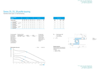
  • 1. Resulting tilting moment (kNm) Axial load (kN) Static boundary load curves Race – – – Bolts 10.9 Bearing without gearing Geometry Attachment Drawing number Ø DL mm Ø Da mm Ø Di mm H mm Ø O mm Ø U mm Ø La mm na Ø B mm Ø Li mm ni Ø B mm 1 250.14.0300.013 Type 13/400 Unhardened race 323 401 233 40 348 298 380 8 14 260 8 14 2 250.14.0400.013 Type 13/500 421 501 333 40 446 396 480 8 14 360 8 14 3 250.15.0300.013 Type 13/400 Hardened race 323 401 233 40 348 298 380 8 14 260 8 14 4 250.15.0400.013 Type 13/500 421 501 333 40 446 396 480 8 14 360 8 14 Miscellaneous kg n1 Y axial mm Y radial mm 9,6 4 ≤ 0,5 ≤ 0,5 13,1 4 ≤ 0,5 ≤ 0,5 9,6 4 ≤ 0,5 ≤ 0,5 13,1 4 ≤ 0,5 ≤ 0,5 H ø Li √ √ ø La ø DL ø Di* √ √ ø B ø Da* n1 7 ,5 7 ø B ≈ ø U ≈ ø O Series 25, 23, 28 profile bearing Standard Series type 13, Normal bearing If centering spigots are required for normal bearings, these must be specified when the order is placed. Centering spigots are only possible if * is indicated for the nominal diameter. For loads above the bolt boundary load curve with raceway boundary load curve 4 the number of fastening bolts must be doubled. Diameter tolerances Machined diameters with untoleranced drawing dimensions have the following tolerances: ≤ 315mm ± 1,6mm ≤ 1000mm ± 2,5mm n1 = Tapered grease nipple H 1a - 6 mm Ø ≈ evenly distributed √ = √ rolled Dimensions of these centering spigots: outside inside Type 13/400 ... 13/500 − 0,5 mm + 0,5 mm Bearing selection series 25, 23, 28 Please contact me if need slewing bearings. Email:wenchen@allslewingbearing.com Whatsapp&wechat:+8617702586093 https://www.allslewingbearing.com Please contact me if need slewing bearings. Email:wenchen@allslewingbearing.com Whatsapp&wechat:+8617702586093 https://www.allslewingbearing.com
  • 2. 80 81 Resulting tilting moment (kNm) Axial load (kN) Static boundary load curves Race – – – Bolts 10.9 Bearing without gearing Geometry Attachment Drawing number Ø DL mm Ø Da mm Ø Di mm H mm Ø O mm Ø U mm Ø La mm na Ø B mm Ø Li mm ni Ø B mm 3 250.15.0375.013 Type 13/400 Hardened race 323 400 − 0,09 234 + 0,07 40 348 298 380 8 14 260 8 14 4 250.15.0475.013 Type 13/500 421 500 − 0,10 334 + 0,09 40 446 396 480 8 14 360 8 14 Miscellaneous kg n1 Y axial + radial mm 9,6 4 ≤ 0 to 0,02 13,1 4 ≤ 0 to 0,02 H ø Li √ √ ø La ø DL ø Di* √ √ ø B ø Da* n1 7 ,5 7 ø B ≈ ø U ≈ ø O Series 25, 23, 28 profile bearing Standard Series type 13, Normal bearing Diameter tolerances Machined diameters with untoleranced drawing dimensions have the following tolerances: ≤ 315mm ± 1,6mm ≤ 1000mm ± 2,5mm n1 = Tapered grease nipple H 1a - 6 mm Ø ≈ evenly distributed √ = √ rolled If centering spigots are required for normal bearings, these must be specified when the order is placed. Centering spigots are only possible if * is indicated for the nominal diameter. For loads above the bolt boundary load curve with raceway boundary load curve 4 the number of fastening bolts must be doubled. Dimensions of these centering spigots: outside inside Type 13/400 ... 13/500 − 0,5 mm + 0,5 mm Bearing selection series 25, 23, 28 Please contact me if need slewing bearings. Email:wenchen@allslewingbearing.com Whatsapp&wechat:+8617702586093 https://www.allslewingbearing.com Please contact me if need slewing bearings. Email:wenchen@allslewingbearing.com Whatsapp&wechat:+8617702586093 https://www.allslewingbearing.com
  • 3. 82 Bearing selection series 25, 23, 28 83 Resulting tilting moment (kNm) Axial load (kN) Static boundary load curves Race – – – Bolts 10.9 Bearing without gearing Geometry Drawing number Ø DL mm Ø Da mm Ø Di mm H mm Ø O mm Ø U mm Ø A mm Ø C mm Hu mm Ho mm 5 230.20.0400.013 Type 21/520.0 414 518 304 56 412,5 415,5 453 375 10,5 10,5 6 230.20.0500.013 Type 21/650.0 544 648 434 56 542,5 545,5 583 505 10,5 10,5 7 230.20.0600.013 Type 21/750.0 644 748 534 56 642,5 645,5 683 605 10,5 10,5 8 230.20.0700.013 Type 21/850.0 744 848 634 56 742,5 745,5 783 705 10,5 10,5 9 230.20.0800.013 Type 21/950.0 844 948 734 56 842,5 845,5 883 805 10,5 10,5 10 230.20.0900.013 Type 21/1050.0 944 1048 834 56 942,5 945,5 983 905 10,5 10,5 11 230.20.1000.013 Type 21/1200.0 1094 1198 984 56 1092,5 1095,5 1133 1055 10,5 10,5 Attachment Miscellaneous Ø La mm na Ø B mm Ø Li mm ni Ø B mm kg n1 Y axial mm Y radial mm 490 8 18 332 12 18 23,4 4 ≤ 0,5 ≤ 0,5 620 10 18 462 14 18 31,0 4 ≤ 0,5 ≤ 0,5 720 12 18 562 16 18 36,4 4 ≤ 0,5 ≤ 0,5 820 12 18 662 16 18 42,8 4 ≤ 0,5 ≤ 0,5 920 14 18 762 18 18 47,8 4 ≤ 0,5 ≤ 0,5 1020 16 18 862 20 18 53,1 4 ≤ 0,5 ≤ 0,5 1170 16 18 1012 20 18 61,9 4 ≤ 0,5 ≤ 0,5 Series 25, 23, 28 profile bearing Standard Series type 21, Normal bearing, normal number of holes profile ring Double number of holes see curves 12 – 18, page 88 Diameter tolerances Machined diameters with untoleranced drawing dimensions have the following tolerances: ≤ 315mm ± 1,6mm ≤ 1000mm ± 2,5mm ≤ 2000mm ± 3,5mm n1 = Tapered grease nipple AM 8 x 1 DIN 71412 ≈ evenly distributed On request, with non-geared bearings, the grease nipples can also be attached on the inner ring. √ = √ rolled If centering spigots are required for nor- mal bearings, these must be specified when the order is placed. Centering spigots are only possible if * is indi- cated for the nominal diameter. For loads above the bolt boundary load curve with raceway boundary load curve 4 the number of fastening bolts must be doubled. Dimensions of these centering spigots: outside inside Type 21/520 ... 21/650 − 0,5 mm + 0,5 mm Type 21/750 ... 21/950 − 0,6 mm + 0,6 mm Type 21/1050 ... 21/1200 − 0,7 mm + 0,7 mm Bearing selection series 25, 23, 28 Please contact me if need slewing bearings. Email:wenchen@allslewingbearing.com Whatsapp&wechat:+8617702586093 https://www.allslewingbearing.com Please contact me if need slewing bearings. Email:wenchen@allslewingbearing.com Whatsapp&wechat:+8617702586093 https://www.allslewingbearing.com
  • 4. 84 Bearing selection series 25, 23, 28 85 Resulting tilting moment (kNm) Axial load (kN) Static boundary load curves Race – – – Bolts 10.9 Centering height HZ * = 4,5 mm Centering height of the companion structure = (HZ − 1) mm Ø Da from 1991 tip relief 0,1 · m Series 25, 23, 28 profile bearing Standard Series type 21, Normal bearing, normal number of holes profile ring Double number of holes see curves 12 – 18, page 90 Diameter tolerances Machined diameters with untoleranced drawing dimensions have the following tolerances: ≤ 315mm ± 1,6mm ≤ 1000mm ± 2,5mm ≤ 2000mm ± 3,5mm n1 = Tapered grease nipple AM 8 x 1 DIN 71412 ≈ evenly distributed √ = √ rolled If centering spigots are required for normal bearings, these must be specified when the order is placed. Centering spigots are only possible if * is indicated for the nominal diameter. For loads above the bolt boundary load curve with raceway boundary load curve 4 the number of fastening bolts must be doubled. Dimensions of these centering spigots: outside inside Type 21/520 ... 21/650 − 0,5 mm + 0,5 mm Type 21/750 ... 21/950 − 0,6 mm + 0,6 mm Type 21/1050 ... 21/1200 − 0,7 mm + 0,7 mm Bearing with external gearing Geometry Attachment Drawing number Ø DL mm Ø Da mm Ø Di mm H mm Ø O mm Ø U mm Ø C mm Hu mm Ø La mm na 5 231.20.0400.013 Type 21/520.1 414 504 304 56 412,5 415,5 375 10,5 455 10 6 231.20.0500.013 Type 21/650.1 544 640,8 434 56 542,5 545,5 505 10,5 585 14 7 231.20.0600.013 Type 21/750.1 644 742,8 534 56 642,5 645,5 605 10,5 685 16 8 231.20.0700.013 Type 21/850.1 744 838,8 634 56 742,5 745,5 705 10,5 785 18 9 231.20.0800.013 Type 21/950.1 844 950,4 734 56 842,5 845,5 805 10,5 885 18 10 231.20.0900.013 Type 21/1050.1 944 1046,4 834 56 942,5 945,5 905 10,5 985 20 11 231.20.1000.013 Type 21/1200.1 1094 1198,4 984 56 1092,5 1095,5 1055 10,5 1135 22 Attachment Gearing Miscellaneous M mm t mm Ø Li mm ni Ø B mm d mm m mm z k · m mm b mm X1 kN X2 kN kg n1 Y axial mm Y radial mm 12 20 332 12 18 495 5 99 − 0,5 45,5 11,75 23,50 29,3 4 ≤ 0,5 ≤ 0,5 12 20 462 14 18 630 6 105 − 0,6 45,5 14,20 28,40 39,5 4 ≤ 0,5 ≤ 0,5 12 20 562 16 18 732 6 122 − 0,6 45,5 14,20 28,40 47,6 4 ≤ 0,5 ≤ 0,5 12 20 662 16 18 828 6 138 − 0,6 45,5 14,20 28,40 53,5 4 ≤ 0,5 ≤ 0,5 12 20 762 18 18 936 8 117 − 0,8 45,5 18,93 37,86 65,1 4 ≤ 0,5 ≤ 0,5 12 20 862 20 18 1032 8 129 − 0,8 45,5 18,93 37,86 69,6 4 ≤ 0,5 ≤ 0,5 12 20 1012 20 18 1184 8 148 − 0,8 45,5 18,93 37,86 83,0 4 ≤ 0,5 ≤ 0,5 Bearing selection series 25, 23, 28 Please contact me if need slewing bearings. Email:wenchen@allslewingbearing.com Whatsapp&wechat:+8617702586093 https://www.allslewingbearing.com Please contact me if need slewing bearings. Email:wenchen@allslewingbearing.com Whatsapp&wechat:+8617702586093 https://www.allslewingbearing.com
  • 5. 86 Bearing selection series 25, 23, 28 87 Resulting tilting moment (kNm) Axial load (kN) Static boundary load curves Race – – – Bolts 10.9 Centering height HZ * = 4,5 mm Centering height of the companion structure = (HZ − 1) mm Bearing with internal gearing Geometry Attachment Drawing number Ø DL mm Ø Da mm Ø Di mm H mm Ø O mm Ø U mm Ø C mm Hu mm Ø La mm na Ø B mm 5 232.20.0400.013 Type 21/520.2 414 518 326,5 56 412,5 415,5 453 10,5 490 8 18 6 232.20.0500.013 Type 21/650.2 544 648 445,2 56 542,5 545,5 583 10,5 620 10 18 7 232.20.0600.013 Type 21/750.2 644 748 547,2 56 642,5 645,5 683 10,5 720 12 18 8 232.20.0700.013 Type 21/850.2 744 848 649,2 56 742,5 745,5 783 10,5 820 12 18 9 232.20.0800.013 Type 21/950.2 844 948 737,6 56 842,5 845,5 883 10,5 920 14 18 10 232.20.0900.013 Type 21/1050.2 944 1048 841,6 56 942,5 945,5 983 10,5 1020 16 18 11 232.20.1000.013 Type 21/1200.2 1094 1198 985,6 56 1092,5 1095,5 1133 10,5 1170 16 18 Attachment Gearing Miscellaneous Ø Li mm ni M mm t mm d mm m mm z k · m mm b mm X1 kN X2 kN kg n1 Y axial mm Y radial mm 375 12 12 20 335 5 67 − 0,75 45,5 13,54 27,08 27,1 4 ≤ 0,5 ≤ 0,5 505 16 12 20 456 6 76 − 0,60 45,5 16,00 32,00 36,9 4 ≤ 0,5 ≤ 0,5 605 18 12 20 558 6 93 − 0,60 45,5 15,62 31,24 43,7 4 ≤ 0,5 ≤ 0,5 705 20 12 20 660 6 110 − 0,60 45,5 15,32 30,64 51,1 4 ≤ 0,5 ≤ 0,5 805 20 12 20 752 8 94 − 0,80 45,5 20,80 41,60 61,6 4 ≤ 0,5 ≤ 0,5 905 22 12 20 856 8 107 − 0,80 45,5 20,49 40,98 65,8 4 ≤ 0,5 ≤ 0,5 1055 24 12 20 1000 8 125 − 0,80 45,5 20,16 40,32 80,7 4 ≤ 0,5 ≤ 0,5 Series 25, 23, 28 profile bearing Standard Series type 21, Normal bearing, normal number of holes profile ring Double number of holes see curves 12 – 18, page 92 If centering spigots are required for normal bearings, these must be specified when the order is placed. Centering spigots are only possible if * is indicated for the nominal diameter. For loads above the bolt boundary load curve with raceway boundary load curve 4 the number of fastening bolts must be doubled. Dimensions of these centering spigots: outside inside Type 21/520 ... 21/650 − 0,5 mm + 0,5 mm Type 21/750 ... 21/950 − 0,6 mm + 0,6 mm Type 21/1050 ... 21/1200 − 0,7 mm + 0,7 mm Diameter tolerances Machined diameters with untoleranced drawing dimensions have the following tolerances: ≤ 1000mm ± 2,5mm ≤ 2000mm ± 3,5mm n1 = Tapered grease nipple AM 8 x 1 DIN 71412 ≈ evenly distributed √ = √ rolled Bearing selection series 25, 23, 28 Please contact me if need slewing bearings. Email:wenchen@allslewingbearing.com Whatsapp&wechat:+8617702586093 https://www.allslewingbearing.com Please contact me if need slewing bearings. Email:wenchen@allslewingbearing.com Whatsapp&wechat:+8617702586093 https://www.allslewingbearing.com
  • 6. 88 Bearing selection series 25, 23, 28 89 Resulting tilting moment (kNm) Axial load (kN) Static boundary load curves Race – – – Bolts 10.9 Bearing without gearing Geometry Drawing number Ø DL mm Ø Da mm Ø Di mm H mm Ø O mm Ø U mm Ø A mm Ø C mm Hu mm Ho mm 12 230.20.0400.503 Type 21/520.0 414 518 304 56 412,5 415,5 453 375 10,5 10,5 13 230.20.0500.503 Type 21/650.0 544 648 434 56 542,5 545,5 583 505 10,5 10,5 14 230.20.0600.503 Type 21/750.0 644 748 534 56 642,5 645,5 683 605 10,5 10,5 15 230.20.0700.503 Type 21/850.0 744 848 634 56 742,5 745,5 783 705 10,5 10,5 16 230.20.0800.503 Type 21/950.0 844 948 734 56 842,5 845,5 883 805 10,5 10,5 17 230.20.0900.503 Type 21/1050.0 944 1048 834 56 942,5 945,5 983 905 10,5 10,5 18 230.20.1000.503 Type 21/1200.0 1094 1198 984 56 1092,5 1095,5 1133 1055 10,5 10,5 Attachment Miscellaneous Ø La mm na Ø B mm Ø Li mm ni Ø B mm kg n1 Y axial mm Y radial mm 490 16 18 332 24 18 23,0 4 ≤ 0,5 ≤ 0,5 620 20 18 462 28 18 30,4 4 ≤ 0,5 ≤ 0,5 720 24 18 562 32 18 35,8 4 ≤ 0,5 ≤ 0,5 820 24 18 662 32 18 42,2 4 ≤ 0,5 ≤ 0,5 920 28 18 762 36 18 47,1 4 ≤ 0,5 ≤ 0,5 1020 32 18 862 40 18 52,3 4 ≤ 0,5 ≤ 0,5 1170 32 18 1012 40 18 61,1 4 ≤ 0,5 ≤ 0,5 Series 25, 23, 28 profile bearing Standard Series type 21, Normal bearing, double number of holes profile ring One hole is missing in the area of the filler plug Diameter tolerances Machined diameters with untoleranced drawing dimensions have the following tolerances: ≤ 315mm ± 1,6mm ≤ 1000mm ± 2,5mm ≤ 2000mm ± 3,5mm n1 = Tapered grease nipple AM 8 x 1 DIN 71412 ≈ evenly distributed On request, with non-geared bearings, the grease nipples can also be attached on the inner ring. √ = √ rolled If centering spigots are required for normal bearings, these must be specified when the order is placed. Centering spigots are only possible if * is indicated for the nominal diameter. Dimensions of these centering spigots: outside inside Type 21/520 ... 21/650 − 0,5 mm + 0,5 mm Type 21/750 ... 21/950 − 0,6 mm + 0,6 mm Type 21/1050 ... 21/1200 − 0,7 mm + 0,7 mm Bearing selection series 25, 23, 28 Please contact me if need slewing bearings. Email:wenchen@allslewingbearing.com Whatsapp&wechat:+8617702586093 https://www.allslewingbearing.com Please contact me if need slewing bearings. Email:wenchen@allslewingbearing.com Whatsapp&wechat:+8617702586093 https://www.allslewingbearing.com
  • 7. 90 Bearing selection series 25, 23, 28 91 Resulting tilting moment (kNm) Axial load (kN) Static boundary load curves Race – – – Bolts 10.9 Ø Da from 1991 tip relief 0,1 · m Centering height HZ * = 4,5 mm Centering height of the companion structure = (HZ − 1) mm Bearing with external gearing Geometry Attachment Drawing number Ø DL mm Ø Da mm Ø Di mm H mm Ø O mm Ø U mm Ø C mm Hu mm Ø La mm na M mm 12 231.20.0400.503 Type 21/520.1 414 504 304 56 412,5 415,5 375 10,5 455 10 12 13 231.20.0500.503 Type 21/650.1 544 640,8 434 56 542,5 545,5 505 10,5 585 14 12 14 231.20.0600.503 Type 21/750.1 644 742,8 534 56 642,5 645,5 605 10,5 685 16 12 15 231.20.0700.503 Type 21/850.1 744 838,8 634 56 742,5 745,5 705 10,5 785 18 12 16 231.20.0800.503 Type 21/950.1 844 950,4 734 56 842,5 845,5 805 10,5 885 18 12 17 231.20.0900.503 Type 21/1050.1 944 1046,4 834 56 942,5 945,5 905 10,5 985 20 12 18 231.20.1000.503 Type 21/1200.1 1094 1198,4 984 56 1092,5 1095,5 1055 10,5 1135 22 12 Attachment Gearing Miscellaneous t mm Ø Li mm ni Ø B mm d mm m mm z k · m mm b mm X1 kN X2 kN kg n1 Y axial mm Y radial mm 20 332 24 18 495 5 99 − 0,5 45,5 11,75 23,50 29,0 4 ≤ 0,5 ≤ 0,5 20 462 28 18 630 6 105 − 0,5 45,5 14,20 28,40 39,2 4 ≤ 0,5 ≤ 0,5 20 562 32 18 732 6 122 − 0,6 45,5 14,20 28,40 47,2 4 ≤ 0,5 ≤ 0,5 20 662 32 18 828 6 138 − 0,6 45,5 14,20 28,40 53,1 4 ≤ 0,5 ≤ 0,5 20 762 36 18 936 8 117 − 0,8 45,5 18,93 37,86 64,7 4 ≤ 0,5 ≤ 0,5 20 862 40 18 1032 8 129 − 0,8 45,5 18,93 37,86 69,1 4 ≤ 0,5 ≤ 0,5 20 1012 40 18 1184 8 148 − 0,8 45,5 18,93 37,86 82,5 4 ≤ 0,5 ≤ 0,5 Series 25, 23, 28 profile bearing Standard Series type 21, Normal bearing, double number of holes profile ring One hole is missing in the area of the filler plug If centering spigots are required for normal bearings, these must be specified when the order is placed. Centering spigots are only possible if * is indicated for the nominal diameter. Dimensions of these centering spigots: outside inside Type 21/520 ... 21/650 − 0,5 mm + 0,5 mm Type 21/750 ... 21/950 − 0,6 mm + 0,6 mm Type 21/1050 ... 21/1200 − 0,7 mm + 0,7 mm Diameter tolerances Machined diameters with untoleranced drawing dimensions have the following tolerances: ≤ 315mm ± 1,6mm ≤ 1000mm ± 2,5mm ≤ 2000mm ± 3,5mm n1 = Tapered grease nipple AM 8 x 1 DIN 71412 ≈ evenly distributed √ = √ rolled Bearing selection series 25, 23, 28 Please contact me if need slewing bearings. Email:wenchen@allslewingbearing.com Whatsapp&wechat:+8617702586093 https://www.allslewingbearing.com Please contact me if need slewing bearings. Email:wenchen@allslewingbearing.com Whatsapp&wechat:+8617702586093 https://www.allslewingbearing.com
  • 8. 92 Bearing selection series 25, 23, 28 93 Resulting tilting moment (kNm) Axial load (kN) Static boundary load curves Race – – – Bolts 10.9 Centering height HZ * = 4,5 mm Centering height of the companion structure = (HZ − 1) mm Bearing with internal gearing Geometry Attachment Drawing number Ø DL mm Ø Da mm Ø Di mm H mm Ø O mm Ø U mm Ø A mm Hu mm Ø La mm na Ø B mm 12 232.20.0400.503 Type 21/520.2 414 518 326,5 56 412,5 415,5 453 10,5 490 16 18 13 232.20.0500.503 Type 21/650.2 544 648 445,2 56 542,5 545,5 583 10,5 620 20 18 14 232.20.0600.503 Type 21/750.2 644 748 547,2 56 642,5 645,5 683 10,5 720 24 18 15 232.20.0700.503 Type 21/850.2 744 848 649,2 56 742,5 745,5 783 10,5 820 24 18 16 232.20.0800.503 Type 21/950.2 844 948 737,6 56 842,5 845,5 883 10,5 920 28 18 17 232.20.0900.503 Type 21/1050.2 944 1048 841,6 56 942,5 945,5 983 10,5 1020 32 18 18 232.20.1000.503 Type 21/1200.2 1094 1198 985,6 56 1092,5 1095,5 1133 10,5 1170 32 18 Attachment Gearing Miscellaneous Ø Li mm ni M mm t mm d mm m mm z k · m mm b mm X1 kN X2 kN kg n1 Y axial mm Y radial mm 375 12 12 20 335 5 67 − 0,75 45,5 13,54 27,08 26,9 4 ≤ 0,5 ≤ 0,5 505 16 12 20 456 6 76 − 0,60 45,5 16,00 32,00 36,7 4 ≤ 0,5 ≤ 0,5 605 18 12 20 558 6 93 − 0,60 45,5 15,62 31,24 43,4 4 ≤ 0,5 ≤ 0,5 705 20 12 20 660 6 110 − 0,60 45,5 15,32 30,64 50,8 4 ≤ 0,5 ≤ 0,5 805 20 12 20 752 8 94 − 0,80 45,5 20,80 41,60 61,3 4 ≤ 0,5 ≤ 0,5 905 22 12 20 856 8 107 − 0,80 45,5 20,49 40,98 65,4 4 ≤ 0,5 ≤ 0,5 1055 24 12 20 1000 8 125 − 0,80 45,5 20,16 40,32 80,3 4 ≤ 0,5 ≤ 0,5 Series 25, 23, 28 profile bearing Standard Series type 21, Normal bearing, double number of holes profile ring One hole is missing in the area of the filler plug If centering spigots are required for normal bearings, these must be specified when the order is placed. Centering spigots are only possible if * is indicated for the nominal diameter. Dimensions of these centering spigots: outside inside Type 21/520 ... 21/650 − 0,5 mm + 0,5 mm Type 21/750 ... 21/950 − 0,6 mm + 0,6 mm Type 21/1050 ... 21/1200 − 0,7 mm + 0,7 mm Diameter tolerances Machined diameters with untoleranced drawing dimensions have the following tolerances: ≤ 1000mm ± 2,5mm ≤ 2000mm ± 3,5mm n1 = Tapered grease nipple AM 8 x 1 DIN 71412 ≈ evenly distributed √ = √ rolled Bearing selection series 25, 23, 28 Please contact me if need slewing bearings. Email:wenchen@allslewingbearing.com Whatsapp&wechat:+8617702586093 https://www.allslewingbearing.com Please contact me if need slewing bearings. Email:wenchen@allslewingbearing.com Whatsapp&wechat:+8617702586093 https://www.allslewingbearing.com
  • 9. 94 Bearing selection series 25, 23, 28 95 Resulting tilting moment (kNm) Axial load (kN) Static boundary load curves Race – – – Bolts 10.9 Bearing without gearing Geometry Drawing number Ø DL mm Ø Da mm Ø Di mm H mm Ø O mm Ø U mm Ø A mm Ø C mm Hu mm Ho mm 5 230.21.0475.013 Type 21/520.0 414 517 − 0,11 305 + 0,08 56 412,5 415,5 453 375 10,5 10,5 6 230.21.0575.013 Type 21/650.0 544 647 − 0,13 435 + 0,10 56 542,5 545,5 583 505 10,5 10,5 7 230.21.0675.013 Type 21/750.0 644 747 − 0,13 535 + 0,11 56 642,5 645,5 683 605 10,5 10,5 8 230.21.0775.013 Type 21/850.0 744 847 − 0,14 635 + 0,13 56 742,5 745,5 783 705 10,5 10,5 9 230.21.0875.013 Type 21/950.0 844 947 − 0,14 735 + 0,13 56 842,5 845,5 883 805 10,5 10,5 10 230.21.0975.013 Type 21/1050.0 944 1047 − 0,17 835 + 0,14 56 942,5 945,5 983 905 10,5 10,5 11 230.21.1075.013 Type 21/1200.0 1094 1197 − 0,17 985 + 0,14 56 1092,5 1095,5 1133 1055 10,5 10,5 Attachment Miscellaneous Ø La mm na Ø B mm Ø Li mm ni Ø B mm kg n1 Y axial + radial mm 490 8 18 332 12 18 23,4 4 ≥ 0 to 0,03 620 10 18 462 14 18 31,0 4 ≥ 0 to 0,03 720 12 18 562 16 18 36,4 4 ≥ 0 to 0,04 820 12 18 662 16 18 42,8 4 ≥ 0 to 0,04 920 14 18 762 18 18 47,8 4 ≥ 0 to 0,05 1020 16 18 862 20 18 53,1 4 ≥ 0 to 0,05 1170 16 18 1012 20 18 61,9 4 ≥ 0 to 0,06 H 12 ø B ø Li √ √ H u ≈ ø C ø La ø DL ø O n1 H o 12 √ √ ø B ø U ≈ ø A ø Da ø Di Series 25, 23, 28 profile bearing Standard Series type 21, Bearing with restricted play For loads above the bolt boundary load curve with raceway boundary load cur- ve 4 the number of fastening bolts must be doubled. Diameter tolerances Machined diameters with untoleranced drawing dimensions have the following tolerances: ≤ 315mm ± 1,6mm ≤ 1000mm ± 2,5mm ≤ 2000mm ± 3,5mm n1 = Tapered grease nipple AM 8 x 1 DIN 71412 ≈ evenly distributed On request, with non-geared bearings, the grease nipples can also be attached on the inner ring. √ = √ rolled Bearing selection series 25, 23, 28 Please contact me if need slewing bearings. Email:wenchen@allslewingbearing.com Whatsapp&wechat:+8617702586093 https://www.allslewingbearing.com Please contact me if need slewing bearings. Email:wenchen@allslewingbearing.com Whatsapp&wechat:+8617702586093 https://www.allslewingbearing.com
  • 10. 96 Bearing selection series 25, 23, 28 97 Resulting tilting moment (kNm) Axial load (kN) Static boundary load curves Race – – – Bolts 10.9 Centering height HZ * = 4,5 mm Centering height of the companion structure = (HZ − 1) mm Ø Da from 1991 tip relief 0,1 · m Bearing with external gearing Geometry Attachment Drawing number Ø DL mm Ø Da mm Ø Di mm H mm Ø O mm Ø U mm Ø C mm Hu mm Ø La mm na M mm 5 231.21.0475.013 Type 21/520.1 414 504 305 + 0,08 56 412,5 417 + 0,10 375 10,5 455 10 12 6 231.21.0575.013 Type 21/650.1 544 640,8 435 + 0,10 56 542,5 547 + 0,11 505 10,5 585 14 12 7 231.21.0675.013 Type 21/750.1 644 742,8 535 + 0,11 56 642,5 647 + 0,13 605 10,5 685 16 12 8 231.21.0775.013 Type 21/850.1 744 838,8 635 + 0,13 56 742,5 747 + 0,13 705 10,5 785 18 12 9 231.21.0875.013 Type 21/950.1 844 950,4 735 + 0,13 56 842,5 847 + 0,14 805 10,5 885 18 12 10 231.21.0975.013 Type 21/1050.1 944 1046,4 835 + 0,14 56 942,5 947 + 0,14 905 10,5 985 20 12 11 231.21.1075.013 Type 21/1200.1 1094 1198,4 985 + 0,14 56 1092,5 1097 + 0,17 1055 10,5 1135 22 12 Attachment Gearing Miscellaneous t mm Ø Li mm ni Ø B mm d mm m mm z k · m mm b mm X1 kN X2 kN kg n1 Y axial + radial mm 20 332 12 18 495 5 99 − 0,5 45,5 11,75 23,50 29,3 4 ≥ 0 to 0,03 20 462 14 18 630 6 105 − 0,6 45,5 14,20 28,40 39,5 4 ≥ 0 to 0,03 20 562 16 18 732 6 122 − 0,6 45,5 14,20 28,40 47,6 4 ≥ 0 to 0,04 20 662 16 18 828 6 138 − 0,6 45,5 14,20 28,40 53,5 4 ≥ 0 to 0,04 20 762 18 18 936 8 117 − 0,8 45,5 18,93 37,86 65,1 4 ≥ 0 to 0,05 20 862 20 18 1032 8 129 − 0,8 45,5 18,93 37,86 69,6 4 ≥ 0 to 0,05 20 1012 20 18 1184 8 148 − 0,8 45,5 18,93 37,86 83,0 4 ≥ 0 to 0,06 M t H 12 ø B ø Li √ √ n1 H z * H u b ≈ ø C ø La ø d ø Da ø DL ø O ø Di ø U Series 25, 23, 28 profile bearing Standard Series type 21, Bearing with restricted play For loads above the bolt boundary load curve with raceway boundary load cur- ve 4 the number of fastening bolts must be doubled. Diameter tolerances Machined diameters with untoleranced drawing dimensions have the following tolerances: ≤ 315mm ± 1,6mm ≤ 1000mm ± 2,5mm ≤ 2000mm ± 3,5mm n1 = Tapered grease nipple AM 8 x 1 DIN 71412 ≈ evenly distributed √ = √ rolled Bearing selection series 25, 23, 28 Please contact me if need slewing bearings. Email:wenchen@allslewingbearing.com Whatsapp&wechat:+8617702586093 https://www.allslewingbearing.com Please contact me if need slewing bearings. Email:wenchen@allslewingbearing.com Whatsapp&wechat:+8617702586093 https://www.allslewingbearing.com
  • 11. 98 Bearing selection series 25, 23, 28 99 Resulting tilting moment (kNm) Axial load (kN) Static boundary load curves Race – – – Bolts 10.9 Centering height HZ * = 4,5 mm Centering height of the companion structure = (HZ − 1) mm Bearing with internal gearing Geometry Attachment Drawing number Ø DL mm Ø Da mm Ø Di mm H mm Ø O mm Ø U mm Ø A mm Hu mm Ø La mm na Ø B mm 5 232.21.0475.013 Type 21/520.2 414 517 − 0,11 326,5 56 411 − 0,10 415,5 453 10,5 490 8 18 6 232.21.0575.013 Type 21/650.2 544 647 − 0,13 445,2 56 541 − 0,11 545,5 583 10,5 620 10 18 7 232.21.0675.013 Type 21/750.2 644 747 − 0,13 547,2 56 641 − 0,13 645,5 683 10,5 720 12 18 8 232.21.0775.013 Type 21/850.2 744 847 − 0,14 649,2 56 741 − 0,13 745,5 783 10,5 820 12 18 9 232.21.0875.013 Type 21/950.2 844 947 − 0,14 737,6 56 841 − 0,14 845,5 883 10,5 920 14 18 10 232.21.0975.013 Type 21/1050.2 944 1047 − 0,17 841,6 56 941 − 0,14 945,5 983 10,5 1020 16 18 11 232.21.1075.013 Type 21/1200.2 1094 1197 − 0,17 985,6 56 1091 − 0,17 1095,5 1133 10,5 1170 16 18 Attachment Gearing Miscellaneous Ø Li mm ni M mm t mm d mm m mm z k · m mm b mm X1 kN X2 kN kg n1 Y axial + radial mm 375 12 12 20 335 5 67 − 0,75 45,5 13,54 27,08 27,1 4 ≥ 0 to 0,03 505 16 12 20 456 6 76 − 0,60 45,5 16,00 32,00 36,9 4 ≥ 0 to 0,03 605 18 12 20 558 6 93 − 0,60 45,5 15,62 31,24 43,7 4 ≥ 0 to 0,04 705 20 12 20 660 6 110 − 0,60 45,5 15,32 30,64 51,1 4 ≥ 0 to 0,04 805 20 12 20 752 8 94 − 0,80 45,5 20,80 41,60 61,6 4 ≥ 0 to 0,05 905 22 12 20 856 8 107 − 0,80 45,5 20,49 40,98 65,8 4 ≥ 0 to 0,05 1055 24 12 20 1000 8 125 − 0,80 45,5 20,16 40,32 80,7 4 ≥ 0 to 0,06 ø d ø La M t b H H u ø Di n1 12 H z * ø B ø U ø DL ø Li ≈ ø A √ √ ø Da ø O Series 25, 23, 28 profile bearing Standard Series type 21, Bearing with restricted play For loads above the bolt boundary load curve with raceway boundary load cur- ve 4 the number of fastening bolts must be doubled. Diameter tolerances Machined diameters with untoleranced drawing dimensions have the following tolerances: ≤ 1000mm ± 2,5mm ≤ 2000mm ± 3,5mm n1 = Tapered grease nipple AM 8 x 1 DIN 71412 ≈ evenly distributed √ = √ rolled Bearing selection series 25, 23, 28 Please contact me if need slewing bearings. Email:wenchen@allslewingbearing.com Whatsapp&wechat:+8617702586093 https://www.allslewingbearing.com Please contact me if need slewing bearings. Email:wenchen@allslewingbearing.com Whatsapp&wechat:+8617702586093 https://www.allslewingbearing.com
  • 12. 100 Bearing selection series 25, 23, 28 101 Resulting tilting moment (kNm) Axial load (kN) Static boundary load curves Race – – – Bolts 10.9 Bearing without gearing Geometry Drawing number Ø DL mm Ø Da mm Ø Di mm H mm Ø O mm Ø U mm Ø A mm Ø C mm Hu mm Ho mm 19 280.30.0900.013 Type 110/1100.0 955 1100 805 90 956,5 953,5 1017 893 19 19 20 280.30.1000.013 Type 110/1200.0 1055 1200 905 90 1056,5 1053,5 1117 993 19 19 21 280.30.1100.013 Type 110/1300.0 1155 1300 1005 90 1156,5 1153,5 1217 1093 19 19 22 280.30.1200.013 Type 110/1400.0 1255 1400 1105 90 1256,5 1253,5 1317 1193 19 19 23 280.30.1300.013 Type 110/1500.0 1355 1500 1205 90 1356,5 1353,5 1417 1293 19 19 24 280.30.1400.013 Type 110/1600.0 1455 1600 1305 90 1456,5 1453,5 1517 1393 19 19 Attachment Miscellaneous Ø La mm na Ø B mm Ø Li mm ni Ø B mm kg n1 Y axial mm Y radial mm 1060 30 22 845 30 22 131 6 ≤ 0,40 ≤ 0,31 1160 30 22 945 30 22 145 6 ≤ 0,40 ≤ 0,31 1260 36 22 1045 36 22 159 6 ≤ 0,40 ≤ 0,31 1360 42 22 1145 42 22 172 6 ≤ 0,45 ≤ 0,37 1460 42 22 1245 42 22 186 6 ≤ 0,45 ≤ 0,37 1560 48 22 1345 48 22 200 6 ≤ 0,45 ≤ 0,37 H ø B ø Li ø La ø Di* H o ø Da* ø U ø A n1 ø B ø C H u ø DL ø O 21 21 Series 25, 23, 28 profile bearing Standard Series type 110, Normal bearing Raceway read-off loads for static boundary load cur- ves and utilization period curves must be found with load factors acc. to Table 1, page 61. Utilization period curves – 30 000 revolutions Diameter tolerances Machined diameters with untoleranced drawing dimensions have the following tolerances: ≤ 1000mm ± 2,5mm ≤ 2000mm ± 3,5mm n1 = Tapered grease nipple AM 8 x 1 DIN 71412 ≈ evenly distributed On request, with non-geared bearings, the grease nipples can also be attached on the inner ring. If centering spigots are required for normal bearings, these must be specified when the order is placed. Centering spigots are only possible if * is indicated for the nominal diameter. Dimensions of these centering spigots: outside inside Type 110/1100 ... 110/1300 − 0,25 mm + 0,25 mm Type 110/1400 ... 110/1600 − 0,30 mm + 0,30 mm Resulting tilting moment (kNm) Axial load (kN) Bearing selection series 25, 23, 28 Please contact me if need slewing bearings. Email:wenchen@allslewingbearing.com Whatsapp&wechat:+8617702586093 https://www.allslewingbearing.com Please contact me if need slewing bearings. Email:wenchen@allslewingbearing.com Whatsapp&wechat:+8617702586093 https://www.allslewingbearing.com
  • 13. 102 Bearing selection series 25, 23, 28 103 Resulting tilting moment (kNm) Axial load (kN) Static boundary load curves Race – – – Bolts 10.9 Ø Da from 1991 tip relief 0,1 · m Bearing with external gearing Geometry Attachment Drawing number Ø DL mm Ø Da mm Ø Di mm H mm Ø O mm Ø U mm Ø C mm Hu mm Ø La mm na M mm 19 281.30.0900.013 Type 110/1100.1 955 1096,2 805 90 956,5 953,5 893 19 1016 30 20 20 281.30.1000.013 Type 110/1200.1 1055 1198 905 90 1056,5 1053,5 993 19 1116 30 20 21 281.30.1100.013 Type 110/1300.1 1155 1298 1005 90 1156,5 1153,5 1093 19 1216 36 20 22 281.30.1200.013 Type 110/1400.1 1255 1398 1105 90 1256,5 1253,5 1193 19 1316 42 20 23 281.30.1300.013 Type 110/1500.1 1355 1498 1205 90 1356,5 1353,5 1293 19 1416 42 20 24 281.30.1400.013 Type 110/1600.1 1455 1598 1305 90 1456,5 1453,5 1393 19 1516 48 20 Attachment Gearing Miscellaneous t mm Ø La mm na Ø B mm d mm m mm z k · m mm b mm X1 kN X2 kN kg n1 Y axial mm Y radial mm 40 845 30 22 1080 9 120 − 0,9 71 32,76 65,52 165 6 ≤ 0,40 ≤ 0,31 40 945 30 22 1180 10 118 − 1,0 71 36,40 72,80 183 6 ≤ 0,40 ≤ 0,31 40 1045 36 22 1280 10 128 − 1,0 71 36,40 72,80 200 6 ≤ 0,40 ≤ 0,31 40 1145 42 22 1380 10 138 − 1,0 71 36,40 72,80 216 6 ≤ 0,45 ≤ 0,37 40 1245 42 22 1480 10 148 − 1,0 71 36,40 72,80 234 6 ≤ 0,45 ≤ 0,37 40 1345 48 22 1580 10 158 − 1,0 71 36,40 72,80 250 6 ≤ 0,45 ≤ 0,37 Centering height HZ = 13 mm Centering height of the companion structure = (HZ − 1) mm Series 25, 23, 28 profile bearing Standard Series type 110, Normal bearing Raceway read-off loads for static boundary load cur- ves and utilization period curves must be found with load factors acc. to Table 1, page 61. Utilization period curves – 30 000 revolutions Diameter tolerances Machined diameters with untoleranced drawing dimensions have the following tolerances: ≤ 1000mm ± 2,5mm ≤ 2000mm ± 3,5mm n1 = Tapered grease nipple AM 8 x 1 DIN 71412 ≈ evenly distributed If centering spigots are required for normal bearings, these must be specified when the order is placed. Centering spigots are only possible if * is indicated for the nominal diameter. Dimensions of these centering spigots: outside inside Type 110/1100 ... 110/1300 − 0,25 mm + 0,25 mm Type 110/1400 ... 110/1600 − 0,30 mm + 0,30 mm Resulting tilting moment (kNm) Axial load (kN) Bearing selection series 25, 23, 28 Please contact me if need slewing bearings. Email:wenchen@allslewingbearing.com Whatsapp&wechat:+8617702586093 https://www.allslewingbearing.com Please contact me if need slewing bearings. Email:wenchen@allslewingbearing.com Whatsapp&wechat:+8617702586093 https://www.allslewingbearing.com
  • 14. 104 Bearing selection series 25, 23, 28 105 Resulting tilting moment (kNm) Axial load (kN) Static boundary load curves Race – – – Bolts 10.9 Bearing with internal gearing Geometry Attachment Drawing number Ø DL mm Ø Da mm Ø Di mm H mm Ø O mm Ø U mm Ø A mm Hu mm Ø La mm na Ø B mm 19 282.30.0900.013 Type 110/1100.2 955 1100 812 90 956,5 953,5 1017 19 1060 30 22 20 282.30.1000.013 Type 110/1200.2 1055 1200 912 90 1056,5 1053,5 1117 19 1160 30 22 21 282.30.1100.013 Type 110/1300.2 1155 1300 1012 90 1156,5 1153,5 1217 19 1260 36 22 22 282.30.1200.013 Type 110/1400.2 1255 1400 1112 90 1256,5 1253,5 1317 19 1360 42 22 23 282.30.1300.013 Type 110/1500.2 1355 1500 1212 90 1356,5 1353,5 1417 19 1460 42 22 24 282.30.1400.013 Type 110/1600.2 1455 1600 1310 90 1456,5 1453,5 1517 19 1560 48 22 Attachment Gearing Miscellaneous Ø Li mm ni M mm t mm d mm m mm z k · m mm b mm X1 kN X2 kN kg n1 Y axial mm Y radial mm 894 30 20 40 830 10 83 − 1,0 71 40,60 81,20 159 6 ≤ 0,40 ≤ 0,31 994 30 20 40 930 10 93 − 1,0 71 40,06 80,12 176 6 ≤ 0,40 ≤ 0,31 1094 36 20 40 1030 10 103 − 1,0 71 39,58 79,16 192 6 ≤ 0,40 ≤ 0,31 1194 42 20 40 1130 10 113 − 1,0 71 39,18 78,36 208 6 ≤ 0,45 ≤ 0,37 1294 42 20 40 1230 10 123 − 1,0 71 38,83 77,66 226 6 ≤ 0,45 ≤ 0,37 1394 48 20 40 1330 10 133 — 71 38,55 77,10 243 6 ≤ 0,45 ≤ 0,37 Series 25, 23, 28 profile bearing Standard Series type 110, Normal bearing Resulting tilting moment (kNm) Axial load (kN) Utilization period curves – 30 000 revolutions Centering height HZ = 13 mm Centering height of the companion structure = (HZ − 1) mm Raceway read-off loads for static boundary load cur- ves and utilization period curves must be found with load factors acc. to Table 1, page 61. Diameter tolerances Machined diameters with untoleranced drawing dimensions have the following tolerances: ≤ 1000mm ± 2,5mm ≤ 2000mm ± 3,5mm n1 = Tapered grease nipple AM 8 x 1 DIN 71412 ≈ evenly distributed If centering spigots are required for normal bearings, these must be specified when the order is placed. Centering spigots are only possible if * is indicated for the nominal diameter. Dimensions of these centering spigots: outside inside Type 110/1100 ... 110/1300 − 0,25 mm + 0,25 mm Type 110/1400 ... 110/1600 − 0,30 mm + 0,30 mm Bearing selection series 25, 23, 28 Please contact me if need slewing bearings. Email:wenchen@allslewingbearing.com Whatsapp&wechat:+8617702586093 https://www.allslewingbearing.com Please contact me if need slewing bearings. Email:wenchen@allslewingbearing.com Whatsapp&wechat:+8617702586093 https://www.allslewingbearing.com
  • 15. Resulting tilting moment (kNm) Axial load (kN) Static boundary load curves Race – – – Bolts 10.9 106 Auswahl Seriesn 25, 23, 28 107 Bearing without gearing Geometry Drawing number Ø DL mm Ø Da mm Ø Di mm H mm Ø O mm Ø U mm Ø A mm Ø C mm Hu mm Ho mm 19 280.30.0975.013 Type 110/1100.0 955 1098 − 0,17 807 + 0,14 90 956,5 953,5 1017 893 19 19 20 280.30.1075.013 Type 110/1200.0 1055 1198 − 0,17 907 + 0,14 90 1056,5 1053,5 1117 993 19 19 21 280.30.1175.013 Type 110/1300.0 1155 1298 − 0,20 1007 + 0,17 90 1156,5 1153,5 1217 1093 19 19 22 280.30.1275.013 Type 110/1400.0 1255 1398 − 0,20 1107 + 0,17 90 1256,5 1253,5 1317 1193 19 19 23 280.30.1375.013 Type 110/1500.0 1355 1498 − 0,20 1207 + 0,17 90 1356,5 1353,5 1417 1293 19 19 24 280.30.1475.013 Type 110/1600.0 1455 1598 − 0,20 1307 + 0,20 90 1456,5 1453,5 1517 1393 19 19 Attachment Miscellaneous Ø La mm na Ø B mm Ø Li mm ni Ø B mm kg n1 Y axial + radial mm 1060 30 22 845 30 22 131 6 ≥ 0 to 0,06 1160 30 22 945 30 22 145 6 ≥ 0 to 0,06 1260 36 22 1045 36 22 159 6 ≥ 0 to 0,06 1360 42 22 1145 42 22 172 6 ≥ 0 to 0,07 1460 42 22 1245 42 22 186 6 ≥ 0 to 0,07 1560 48 22 1345 48 22 200 6 ≥ 0 to 0,07 Series 25, 23, 28 profile bearing Standard Series type 110, Bearing with restricted play Resulting tilting moment (kNm) Axial load (kN) Utilization period curves – 30 000 revolutions Raceway read-off loads for static boundary load cur- ves and utilization period curves must be found with load factors acc. to Table 1, page 61. Diameter tolerances Machined diameters with untoleranced drawing dimensions have the following tolerances: ≤ 1000mm ± 2,5mm ≤ 2000mm ± 3,5mm n1 = Tapered grease nipple AM 8 x 1 DIN 71412 ≈ evenly distributed On request, with non-geared bearings, the grease nipples can also be attached on the inner ring. Auswahl Seriesn 25, 23, 28 Please contact me if need slewing bearings. Email:wenchen@allslewingbearing.com Whatsapp&wechat:+8617702586093 https://www.allslewingbearing.com Please contact me if need slewing bearings. Email:wenchen@allslewingbearing.com Whatsapp&wechat:+8617702586093 https://www.allslewingbearing.com
  • 16. 108 Bearing selection series 25, 23, 28 109 Resulting tilting moment (kNm) Axial load (kN) Static boundary load curves Race – – – Bolts 10.9 Ø Da from 1991 tip relief 0,1 · m Bearing with external gearing Geometry Attachment Drawing number Ø DL mm Ø Da mm Ø Di mm H mm Ø O mm Ø U mm Ø C mm Hu mm Ø La mm na M mm 19 281.30.0975.013 Type 110/1100.1 955 1096,2 807 + 0,14 90 956,5 955 + 0,14 893 19 1016 30 20 20 281.30.1075.013 Type 110/1200.1 1055 1198 907 + 0,14 90 1056,5 1055 + 0,17 993 19 1116 30 20 21 281.30.1175.013 Type 110/1300.1 1155 1298 1007 + 0,17 90 1156,5 1155 + 0,17 1093 19 1216 36 20 22 281.30.1275.013 Type 110/1400.1 1255 1398 1107 + 0,17 90 1256,5 1255 + 0,20 1193 19 1316 42 20 23 281.30.1375.013 Type 110/1500.1 1355 1498 1207 + 0,17 90 1356,5 1355 + 0,20 1293 19 1416 42 20 24 281.30.1475.013 Type 110/1600.1 1455 1598 1307 + 0,20 90 1456,5 1455 + 0,20 1393 19 1516 48 20 Attachment Gearing Miscellaneous t mm Ø Li mm ni Ø B mm d mm m mm z k · m mm b mm X1 kN X2 kN kg n1 Y axial + radial mm 40 845 30 22 1080 9 120 − 0,9 71 32,76 65,52 165 6 ≥ 0 to 0,06 40 945 30 22 1180 10 118 − 1,0 71 36,40 72,80 183 6 ≥ 0 to 0,06 40 1045 36 22 1280 10 128 − 1,0 71 36,40 72,80 200 6 ≥ 0 to 0,06 40 1145 42 22 1380 10 138 − 1,0 71 36,40 72,80 216 6 ≥ 0 to 0,07 40 1245 42 22 1480 10 148 − 1,0 71 36,40 72,80 234 6 ≥ 0 to 0,07 40 1345 48 22 1580 10 158 − 1,0 71 36,40 72,80 250 6 ≥ 0 to 0,07 Series 25, 23, 28 profile bearing Standard Series type 110, Bearing with restricted play Resulting tilting moment (kNm) Axial load (kN) Utilization period curves – 30 000 revolutions Centering height HZ * = 13 mm Centering height of the companion structure = (HZ − 1) mm Raceway read-off loads for static boundary load cur- ves and utilization period curves must be found with load factors acc. to Table 1, page 61. Diameter tolerances Machined diameters with untoleranced drawing dimensions have the following tolerances: ≤ 1000mm ± 2,5mm ≤ 2000mm ± 3,5mm n1 = Tapered grease nipple AM 8 x 1 DIN 71412 ≈ evenly distributed Bearing selection series 25, 23, 28 Please contact me if need slewing bearings. Email:wenchen@allslewingbearing.com Whatsapp&wechat:+8617702586093 https://www.allslewingbearing.com Please contact me if need slewing bearings. Email:wenchen@allslewingbearing.com Whatsapp&wechat:+8617702586093 https://www.allslewingbearing.com
  • 17. 110 Bearing selection series 25, 23, 28 111 Resulting tilting moment (kNm) Axial load (kN) Static boundary load curves Race – – – Bolts 10.9 Bearing with internal gearing Geometry Attachment Drawing number Ø DL mm Ø Da mm Ø Di mm H mm Ø O mm Ø U mm Ø A mm Hu mm Ø La mm na Ø B mm 19 282.30.0975.013 Type 110/1100.2 955 1098 − 0,17 812 90 955 − 0,14 953,5 1017 19 1060 30 22 20 282.30.1075.013 Type 110/1200.2 1055 1198 − 0,17 912 90 1055 − 0,17 1053,5 1117 19 1160 30 22 21 282.30.1175.013 Type 110/1300.2 1155 1298 − 0,20 1012 90 1155 − 0,17 1153,5 1217 19 1260 36 22 22 282.30.1275.013 Type 110/1400.2 1255 1398 − 0,20 1112 90 1255 − 0,20 1253,5 1317 19 1360 42 22 23 282.30.1375.013 Type 110/1500.2 1355 1498 − 0,20 1212 90 1355 − 0,20 1353,5 1417 19 1460 42 22 24 282.30.1475.013 Type 110/1600.2 1455 1598 − 0,20 1310 90 1455 − 0,20 1453,5 1517 19 1560 48 22 Attachment Gearing Miscellaneous Ø Li mm ni M mm t mm d mm m mm z k · m mm b mm X1 kN X2 kN kg n1 Y axial + radial mm 894 30 20 40 830 10 83 − 1,0 71 40,60 81,20 159 6 ≥ 0 to 0,06 994 30 20 40 930 10 93 − 1,0 71 40,06 80,12 176 6 ≥ 0 to 0,06 1094 36 20 40 1030 10 103 − 1,0 71 39,58 79,16 192 6 ≥ 0 to 0,06 1194 42 20 40 1130 10 113 − 1,0 71 39,18 78,36 208 6 ≥ 0 to 0,07 1294 42 20 40 1230 10 123 − 1,0 71 38,83 77,66 226 6 ≥ 0 to 0,07 1394 48 20 40 1330 10 133 — 71 38,55 77,10 243 6 ≥ 0 to 0,07 Series 25, 23, 28 profile bearing Standard Series type 110, Bearing with restricted play Resulting tilting moment (kNm) Axial load (kN) Utilization period curves – 30 000 revolutions Centering height HZ * = 13 mm Centering height of the companion structure = (HZ − 1) mm Raceway read-off loads for static boundary load cur- ves and utilization period curves must be found with load factors acc. to Table 1, page 61. Diameter tolerances Machined diameters with untoleranced drawing dimensions have the following tolerances: ≤ 1000mm ± 2,5mm ≤ 2000mm ± 3,5mm n1 = Tapered grease nipple AM 8 x 1 DIN 71412 ≈ evenly distributed Bearing selection series 25, 23, 28 Please contact me if need slewing bearings. Email:wenchen@allslewingbearing.com Whatsapp&wechat:+8617702586093 https://www.allslewingbearing.com Please contact me if need slewing bearings. Email:wenchen@allslewingbearing.com Whatsapp&wechat:+8617702586093 https://www.allslewingbearing.com
  • 18. 112 Bearing selection series 06 113 Resulting tilting moment (kNm) Axial load (kN) Resulting tilting moment (kNm) Axial load (kN) Static boundary load curves Race – – – Bolts 10.9 Utilization period curves – 30 000 revolutions Bearing without gearing Geometry Drawing number Ø DL mm Ø Da mm Ø Di mm H mm Ø O mm Ø U mm H1 mm H2 mm Hu mm Ho mm 1 060.22.0370.301.11.1504 370 456 289 59 371 369 50 50 9 9 2 060.22.0505.000.11.1503 505 585 425 58 506 504 49 49 9 9 3 060.22.0575.502.11.1503 575 655 500 62 576 574 49 49 13 13 4 060.22.0660.001.11.1503 660 740 580 58 657 659 49 49 9 9 Attachment Miscellaneous Ø La mm Ø Li mm n Ø B mm M mm kg n1 425 320 16 17,5 16 35 4 555 455 22 17,5 16 44 2 625 525 12 — 16 52 4 710 610 30 17,5 16 59 2 Series 06 Single-row four-point bearing Drawing number 060.22.0370.301.11.1504 060.22.0505.000.11.1503 060.22.0660.001.11.1503 Drawing number 060.22.0575.502.11.1503 Diameter tolerances Machined diameters with untoleranced drawing dimensions have the following tolerances: ≤ 315mm ± 1,6mm ≤ 1000mm ± 2,5mm Bearing selection series 06 Please contact me if need slewing bearings. Email:wenchen@allslewingbearing.com Whatsapp&wechat:+8617702586093 https://www.allslewingbearing.com Please contact me if need slewing bearings. Email:wenchen@allslewingbearing.com Whatsapp&wechat:+8617702586093 https://www.allslewingbearing.com
  • 19. 114 Bearing selection series 06 115 Resulting tilting moment (kNm) Axial load (kN) Resulting tilting moment (kNm) Axial load (kN) Static boundary load curves Race – – – Bolts 10.9 Utilization period curves – 30 000 revolutions H H 1 H o n1 ø Da ø La ø U ø O ø DL ø Li ø Di H 2 H u ø B ø B Bearing without gearing Geometry Drawing number Ø DL mm Ø Da mm Ø Di mm H mm Ø O mm Ø U mm H1 mm H2 mm Hu mm Ho mm 5 060.25.0475.000.11.1504 475 565 385 64 476 474 57 57 7 7 6 060.25.0555.000.11.1504 555 650 460 63 556 554 54 54 9 9 7 060.30.0550.100.11.1504 555 650 450 75 548 552 65 65 10 10 8 060.35.0680.000.11.1503 680 800 560 82 681 678 73 73 9 9 9 060.45.0805.001.11.1504 805 948 662 99 807 803 90 90 9 9 Attachment Miscellaneous Ø La mm Ø Li mm n Ø B mm M mm kg n1 535 415 30 17,5 16 50 3 614 496 30 17,5 16 61 3 615 485 24 22,0 20 73 4 755 605 20 22,0 20 131 4 896 714 30 26,0 24 215 4 Series 06 Single-row four-point bearing Diameter tolerances Machined diameters with untoleranced drawing dimensions have the following tolerances: ≤ 1000mm ± 2,5mm Bearing selection series 06 Please contact me if need slewing bearings. Email:wenchen@allslewingbearing.com Whatsapp&wechat:+8617702586093 https://www.allslewingbearing.com Please contact me if need slewing bearings. Email:wenchen@allslewingbearing.com Whatsapp&wechat:+8617702586093 https://www.allslewingbearing.com
  • 20. 116 Bearing selection series 06 117 Resulting tilting moment (kNm) Axial load (kN) Resulting tilting moment (kNm) Axial load (kN) Static boundary load curves Race – – – Bolts 10.9 Utilization period curves – 30 000 revolutions H H 1 H o ø La ø U ø O ø DL ø Li H 2 H u ø B ø B ø Di* ø Da* H A H i n1 Bearing without gearing Geometry Drawing number Ø DL mm Ø Da mm Ø Di mm H mm Ø O mm Ø U mm H1 mm H2 mm Hu mm Ho mm 1 060.20.0414.500.01.1503 414 486 342 56 412,5 415,5 45,5 45,5 10,5 10,5 2 060.20.0544.500.01.1503 544 616 472 56 542,5 545,5 45,5 45,5 10,5 10,5 3 060.20.0644.500.01.1503 644 716 572 56 642,5 645,5 45,5 45,5 10,5 10,5 4 060.20.0744.500.01.1503 744 816 672 56 742,5 745,5 45,5 45,5 10,5 10,5 5 060.20.0844.500.01.1503 844 916 772 56 842,5 845,5 45,5 45,5 10,5 10,5 6 060.20.0944.500.01.1503 944 1016 872 56 942,5 945,5 45,5 45,5 10,5 10,5 7 060.20.1094.500.01.1503 1094 1166 1022 56 1092,5 1095,5 45,5 45,5 10,5 10,5 Attachment Miscellaneous Ø La mm Ø Li mm n Ø B mm M mm kg Y axial mm Y radial mm 460 368 24 13,5 12 29 ≤ 0,28 ≤ 0,24 590 498 32 13,5 12 37 ≤ 0,30 ≤ 0,26 690 598 36 13,5 12 44 ≤ 0,30 ≤ 0,26 790 698 40 13,5 12 52 ≤ 0,30 ≤ 0,26 890 798 40 13,5 12 60 ≤ 0,30 ≤ 0,26 990 898 44 13,5 12 67 ≤ 0,30 ≤ 0,26 1140 1048 48 13,5 12 77 ≤ 0,30 ≤ 0,26 centering spigots are required, these must be specified when the order is placed. Centering spigots are only possible if * is indi- cated for the nomi- nal Ø. Dimensions of these centering spigots: outside inside DL 414, 544 − 0,5 mm + 0,5 mm DL 644, 744, 844 − 0,6 mm + 0,6 mm DL 944, 1094 − 0,7 mm + 0,7 mm Centering height Hi = 10 mm HA = 10 mm Centering height of the companion structure max. 9 mm Diameter tolerances Machined diameters with untoleranced drawing dimensions have the following tolerances: ≤ 1000mm ± 2,5mm ≤ 2000mm ± 3,5mm n1 = 4 Tapered grease nipple AM 10 x 1 DIN 71412 countersunk and evenly distributed Series 06 Single-row four-point bearing Standard Series type 621, Normal bearing Bearing selection series 06 Please contact me if need slewing bearings. Email:wenchen@allslewingbearing.com Whatsapp&wechat:+8617702586093 https://www.allslewingbearing.com Please contact me if need slewing bearings. Email:wenchen@allslewingbearing.com Whatsapp&wechat:+8617702586093 https://www.allslewingbearing.com
  • 21. 118 Bearing selection series 06 119 Resulting tilting moment (kNm) Axial load (kN) Resulting tilting moment (kNm) Axial load (kN) Static boundary load curves Race – – – Bolts 10.9 Utilization period curves – 30 000 revolutions Bearing with external gearing Geometry Drawing number Ø DL mm Ø Da mm Ø Di mm H mm Ø O mm Ø U mm H1 mm H2 mm Hu mm Ho mm 1 061.20.0414.500.01.1503 414 504,0 342 56 412,5 415,5 45,5 45,5 10,5 10,5 2 061.20.0544.500.01.1503 544 640,8 472 56 542,5 545,5 45,5 45,5 10,5 10,5 3 061.20.0644.500.01.1503 644 742,8 572 56 642,5 645,5 45,5 45,5 10,5 10,5 4 061.20.0744.500.01.1503 744 838,8 672 56 742,5 745,5 45,5 45,5 10,5 10,5 5 061.20.0844.500.01.1503 844 950,4 772 56 842,5 845,5 45,5 45,5 10,5 10,5 6 061.20.0944.500.01.1503 944 1046,4 872 56 942,5 945,5 45,5 45,5 10,5 10,5 7 061.20.1094.500.01.1503 1094 1198,4 1022 56 1092,5 1095,5 45,5 45,5 10,5 10,5 Attachment Gearing Miscellaneous Ø La mm Ø Li mm n La /Li Ø B mm M mm t mm d mm m mm z k · m mm b mm X1 kN X2 kN kg Y axial mm Y radial mm 455 368 20/24 13,5 12 20 495 5 99 − 0,5 45,5 11,75 23,50 31 ≤ 0,28 ≤ 0,24 585 498 28/32 13,5 12 20 630 6 105 − 0,6 45,5 14,20 28,40 43 ≤ 0,30 ≤ 0,26 685 598 32/36 13,5 12 20 732 6 122 − 0,6 45,5 14,20 28,40 52 ≤ 0,30 ≤ 0,26 785 698 36/40 13,5 12 20 828 6 138 − 0,6 45,5 14,20 28,40 59 ≤ 0,30 ≤ 0,26 885 798 36/40 13,5 12 20 936 8 117 − 0,8 45,5 18,93 37,86 71 ≤ 0,30 ≤ 0,26 985 898 40/44 13,5 12 20 1032 8 129 − 0,8 45,5 18,93 37,86 77 ≤ 0,30 ≤ 0,26 1135 1048 44/48 13,5 12 20 1184 8 148 − 0,8 45,5 18,93 37,86 91 ≤ 0,30 ≤ 0,26 Series 06 Single-row four-point bearing Standard Series type 621, Normal bearing If centering spigots are required, these must be specified when the order is placed. Centering spigots are only possible if * is indi- cated for the nomi- nal Ø. Dimensions of these centering spigots: outside inside DL 414, 544 − 0,5 mm + 0,5 mm DL 644, 744, 844 − 0,6 mm + 0,6 mm DL 944, 1094 − 0,7 mm + 0,7 mm Centering height Hi = 10 mm HZ = 4,5 mm Centering height of the companion structure max. Hi −1 mm max. HZ −1 mm Diameter tolerances Machined diameters with untoleranced drawing dimensions have the following tolerances: ≤ 1000mm ± 2,5mm ≤ 2000mm ± 3,5mm n1 = 4 Tapered grease nipple AM 10 x 1 DIN 71412 countersunk and evenly distributed Bearing selection series 06 Please contact me if need slewing bearings. Email:wenchen@allslewingbearing.com Whatsapp&wechat:+8617702586093 https://www.allslewingbearing.com Please contact me if need slewing bearings. Email:wenchen@allslewingbearing.com Whatsapp&wechat:+8617702586093 https://www.allslewingbearing.com
  • 22. 120 Bearing selection series 06 121 Resulting tilting moment (kNm) Axial load (kN) Resulting tilting moment (kNm) Axial load (kN) Static boundary load curves Race – – – Bolts 10.9 Utilization period curves – 30 000 revolutions Bearing with internal gearing Geometry Drawing number Ø DL mm Ø Da mm Ø Di mm H mm Ø O mm Ø U mm H1 mm H2 mm Hu mm Ho mm 1 062.20.0414.500.01.1503 414 486 326,5 56 415,5 412,5 45,5 45,5 10,5 10,5 2 062.20.0544.500.01.1503 544 616 445,2 56 545,5 542,5 45,5 45,5 10,5 10,5 3 062.20.0644.500.01.1503 644 716 547,2 56 645,5 642,5 45,5 45,5 10,5 10,5 4 062.20.0744.500.01.1503 744 816 649,2 56 745,5 742,5 45,5 45,5 10,5 10,5 5 062.20.0844.500.01.1503 844 916 737,6 56 845,5 842,5 45,5 45,5 10,5 10,5 6 062.20.0944.500.01.1503 944 1016 841,6 56 945,5 942,5 45,5 45,5 10,5 10,5 7 062.20.1094.500.01.1503 1094 1166 985,6 56 1095,5 1092,5 45,5 45,5 10,5 10,5 Attachment Gearing Miscellaneous Ø La mm Ø Li mm n Ø B mm M mm t mm d mm m mm z k · m mm b mm X1 kN X2 kN kg Y axial mm Y radial mm 460 375 24 13,5 12 20 335 5 67 − 0,75 45,5 13,54 27,08 31 ≤ 0,28 ≤ 0,28 590 505 32 13,5 12 20 456 6 76 − 0,60 45,5 16,00 32,00 42 ≤ 0,30 ≤ 0,30 690 605 36 13,5 12 20 558 6 93 − 0,60 45,5 15,62 31,24 50 ≤ 0,30 ≤ 0,30 790 705 40 13,5 12 20 660 6 110 − 0,60 45,5 15,32 30,64 58 ≤ 0,30 ≤ 0,30 890 805 40 13,5 12 20 752 8 94 − 0,80 45,5 20,80 41,60 69 ≤ 0,30 ≤ 0,30 990 905 44 13,5 12 20 856 8 107 − 0,80 45,5 20,49 40,98 76 ≤ 0,30 ≤ 0,30 1140 1055 48 13,5 12 20 1000 8 125 − 0,80 45,5 20,16 40,32 91 ≤ 0,30 ≤ 0,30 Series 06 Single-row four-point bearing Standard Series type 621, Normal bearing If centering spigots are required, these must be specified when the order is placed. Centering spigots are only possible if * is indi- cated for the nomi- nal Ø. Dimensions of these centering spigots: outside inside DL 414, 544 − 0,5 mm + 0,5 mm DL 644, 744, 844 − 0,6 mm + 0,6 mm DL 944, 1094 − 0,7 mm + 0,7 mm Centering height HZ = 4,5 mm HA = 10 mm Centering height of the companion structure max. HZ −1 mm max. HA −1 mm Diameter tolerances Machined diameters with untoleranced drawing dimensions have the following tolerances: ≤ 1000mm ± 2,5mm ≤ 2000mm ± 3,5mm n1 = 4 Tapered grease nipple AM 10 x 1 DIN 71412 countersunk and evenly distributed Bearing selection series 06 Please contact me if need slewing bearings. Email:wenchen@allslewingbearing.com Whatsapp&wechat:+8617702586093 https://www.allslewingbearing.com Please contact me if need slewing bearings. Email:wenchen@allslewingbearing.com Whatsapp&wechat:+8617702586093 https://www.allslewingbearing.com
  • 23. 122 Bearing selection series 06 123 Resulting tilting moment (kNm) Axial load (kN) Resulting tilting moment (kNm) Axial load (kN) Static boundary load curves Race – – – Bolts 10.9 Utilization period curves – 30 000 revolutions H H 1 H o ø La ø U ø O ø DL ø Li H 2 H u ø B ø B H A H i n1 ø Da ø Di Bearing without gearing Geometry Drawing number Ø DL mm Ø Da mm Ø Di mm H mm Ø O mm Ø U mm H1 mm H2 mm Hu mm Ho mm 1 060.20.0414.575.01.1403 414 484,5 − 0,10 343,5 + 0,09 56 412,5 415,5 45,5 45,5 10,5 10,5 2 060.20.0544.575.01.1403 544 614,5 − 0,11 473,5 + 0,10 56 542,5 545,5 45,5 45,5 10,5 10,5 3 060.20.0644.575.01.1403 644 714,5 − 0,13 573,5 + 0,11 56 642,5 645,5 45,5 45,5 10,5 10,5 4 060.20.0744.575.01.1403 744 814,5 − 0,14 673,5 + 0,13 56 742,5 745,5 45,5 45,5 10,5 10,5 5 060.20.0844.575.01.1403 844 914,5 − 0,14 773,5 + 0,13 56 842,5 845,5 45,5 45,5 10,5 10,5 6 060.20.0944.575.01.1403 944 1014,5 − 0,17 873,5 + 0,14 56 942,5 945,5 45,5 45,5 10,5 10,5 7 060.20.1094.575.01.1403 1094 1164,5 − 0,17 1023,5 + 0,17 56 1092,5 1095,5 45,5 45,5 10,5 10,5 Attachment Miscellaneous Ø La mm Ø Li mm n* Ø B mm M mm kg Y axial + radial mm 460 368 24 13,5 12 29 ≥ 0 to 0,03 590 498 32 13,5 12 37 ≥ 0 to 0,03 690 598 36 13,5 12 44 ≥ 0 to 0,04 790 698 40 13,5 12 52 ≥ 0 to 0,04 890 798 40 13,5 12 60 ≥ 0 to 0,05 990 898 44 13,5 12 67 ≥ 0 to 0,05 1140 1048 48 13,5 12 77 ≥ 0 to 0,06 Series 06 Single-row four-point bearing Standard Series type 621, Bearing with restricted play * Tolerance data applies in each case to Hi , HA Centering height Hi = 10 mm HA = 10 mm Centering height of the companion structure max. 9 mm Diameter tolerances Machined diameters with untoleranced drawing dimensions have the following tolerances: ≤ 1000mm ± 2,5mm ≤ 2000mm ± 3,5mm n1 = 4 Tapered grease nipple AM 10 x 1 DIN 71412 countersunk and evenly distributed Bearing selection series 06 Please contact me if need slewing bearings. Email:wenchen@allslewingbearing.com Whatsapp&wechat:+8617702586093 https://www.allslewingbearing.com Please contact me if need slewing bearings. Email:wenchen@allslewingbearing.com Whatsapp&wechat:+8617702586093 https://www.allslewingbearing.com
  • 24. 124 Bearing selection series 06 125 Resulting tilting moment (kNm) Axial load (kN) Resulting tilting moment (kNm) Axial load (kN) Static boundary load curves Race – – – Bolts 10.9 Utilization period curves – 30 000 revolutions H o ø La ø O ø DL ø Li H 2 H u ø B H i t ø Da H 1 ; b ø d H M H z n1 ø Di ø U Bearing with external gearing Geometry Drawing number Ø DL mm Ø Da mm Ø Di mm H mm Ø O mm Ø U mm H1 mm H2 mm Hu mm Ho mm 1 061.20.0414.575.01.1403 414 504,0 343,5 + 0,09 56 412,5 417 + 0,10 45,5 45,5 10,5 10,5 2 061.20.0544.575.01.1403 544 640,8 473,5 + 0,10 56 542,5 547 + 0,11 45,5 45,5 10,5 10,5 3 061.20.0644.575.01.1403 644 742,8 573,5 + 0,11 56 642,5 647 + 0,13 45,5 45,5 10,5 10,5 4 061.20.0744.575.01.1403 744 838,8 673,5 + 0,13 56 742,5 747 + 0,13 45,5 45,5 10,5 10,5 5 061.20.0844.575.01.1403 844 950,4 773,5 + 0,13 56 842,5 847 + 0,14 45,5 45,5 10,5 10,5 6 061.20.0944.575.01.1403 944 1046,4 873,5 + 0,14 56 942,5 947 + 0,14 45,5 45,5 10,5 10,5 7 061.20.1094.575.01.1403 1094 1198,4 1023,5 + 0,17 56 1092,5 1097 + 0,17 45,5 45,5 10,5 10,5 Attachment Gearing Miscellaneous Ø La mm Ø Li mm n La /Li Ø B mm M mm t mm d mm m mm z k · m mm b mm X1 kN X2 kN kg Y axial + radial mm 455 368 20/24 13,5 12 20 495 5 99 − 0,5 45,5 11,75 23,50 31 ≥ 0 to 0,03 585 498 28/32 13,5 12 20 630 6 105 − 0,6 45,5 14,20 28,40 43 ≥ 0 to 0,03 685 598 32/36 13,5 12 20 732 6 122 − 0,6 45,5 14,20 28,40 52 ≥ 0 to 0,04 785 698 36/40 13,5 12 20 828 6 138 − 0,6 45,5 14,20 28,40 59 ≥ 0 to 0,04 885 798 36/40 13,5 12 20 936 8 117 − 0,8 45,5 18,93 37,86 71 ≥ 0 to 0,05 985 898 40/44 13,5 12 20 1032 8 129 − 0,8 45,5 18,93 37,86 77 ≥ 0 to 0,05 1135 1048 44/48 13,5 12 20 1184 8 148 − 0,8 45,5 18,93 37,86 91 ≥ 0 to 0,06 Series 06 Single-row four-point bearing Standard Series type 621, Bearing with restricted play * Tolerance data applies in each case to Hi , HZ Centering height Hi = 10 mm HZ = 4,5 mm Centering height of the companion structure max. Hi −1 mm max. HZ −1 mm Diameter tolerances Machined diameters with untoleranced drawing dimensions have the following tolerances: ≤ 1000mm ± 2,5mm ≤ 2000mm ± 3,5mm n1 = 4 Tapered grease nipple AM 10 x 1 DIN 71412 countersunk and evenly distributed Bearing selection series 06 Please contact me if need slewing bearings. Email:wenchen@allslewingbearing.com Whatsapp&wechat:+8617702586093 https://www.allslewingbearing.com Please contact me if need slewing bearings. Email:wenchen@allslewingbearing.com Whatsapp&wechat:+8617702586093 https://www.allslewingbearing.com
  • 25. 126 Bearing selection series 06 127 Resulting tilting moment (kNm) Axial load (kN) Resulting tilting moment (kNm) Axial load (kN) Static boundary load curves Race – – – Bolts 10.9 Utilization period curves – 30 000 revolutions ø O ø DL ø B M t H o H 1 ; b H H A H z H u H 2 ø La ø Li ø d ø Di n1 ø Da ø U Bearing with internal gearing Geometry Drawing number Ø DL mm Ø Da mm Ø Di mm H mm Ø O mm Ø U mm H1 mm H2 mm Hu mm Ho mm 1 062.20.0414.575.01.1403 414 484,5 − 0,10 326,5 56 415,5 411 − 0,10 45,5 45,5 10,5 10,5 2 062.20.0544.575.01.1403 544 614,5 − 0,11 445,2 56 545,5 541 − 0,11 45,5 45,5 10,5 10,5 3 062.20.0644.575.01.1403 644 714,5 − 0,13 547,2 56 645,5 641 − 0,13 45,5 45,5 10,5 10,5 4 062.20.0744.575.01.1403 744 814,5 − 0,14 649,2 56 745,5 741 − 0,13 45,5 45,5 10,5 10,5 5 062.20.0844.575.01.1403 844 914,5 − 0,14 737,6 56 845,5 841 − 0,14 45,5 45,5 10,5 10,5 6 062.20.0944.575.01.1403 944 1014,5 − 0,17 841,6 56 945,5 941 − 0,14 45,5 45,5 10,5 10,5 7 062.20.1094.575.01.1403 1094 1164,5 − 0,17 985,6 56 1095,5 1091 − 0,17 45,5 45,5 10,5 10,5 Attachment Gearing Miscellaneous Ø La mm Ø Li mm n Ø B mm M mm t mm d mm m mm z k · m mm b mm X1 kN X2 kN kg Y axial + radial mm 460 375 24 13,5 12 20 335 5 67 − 0,75 45,5 13,54 27,08 31 ≥ 0 to 0,03 590 505 32 13,5 12 20 456 6 76 − 0,60 45,5 16,00 32,00 42 ≥ 0 to 0,03 690 605 36 13,5 12 20 558 6 93 − 0,60 45,5 15,62 31,24 50 ≥ 0 to 0,04 790 705 40 13,5 12 20 660 6 110 − 0,60 45,5 15,32 30,64 58 ≥ 0 to 0,04 890 805 40 13,5 12 20 752 8 94 − 0,80 45,5 20,80 41,60 69 ≥ 0 to 0,05 990 905 44 13,5 12 20 856 8 107 − 0,80 45,5 20,49 40,98 76 ≥ 0 to 0,05 1140 1055 48 13,5 12 20 1000 8 125 − 0,80 45,5 20,16 40,32 91 ≥ 0 to 0,06 Series 06 Single-row four-point bearing Standard Series type 621, Bearing with restricted play * Tolerance data applies in each case to HA , HZ Centering height HZ = 4,5 mm HA = 10 mm Centering height of the companion structure max. HZ −1 mm max. HA −1 mm Diameter tolerances Machined diameters with untoleranced drawing dimensions have the following tolerances: ≤ 1000mm ± 2,5mm ≤ 2000mm ± 3,5mm n1 = 4 Tapered grease nipple AM 10 x 1 DIN 71412 countersunk and evenly distributed Bearing selection series 06 Please contact me if need slewing bearings. Email:wenchen@allslewingbearing.com Whatsapp&wechat:+8617702586093 https://www.allslewingbearing.com Please contact me if need slewing bearings. Email:wenchen@allslewingbearing.com Whatsapp&wechat:+8617702586093 https://www.allslewingbearing.com
  • 26. 128 Bearing selection series 06 129 Resulting tilting moment (kNm) Axial load (kN) Resulting tilting moment (kNm) Axial load (kN) Static boundary load curves Race – – – Bolts 10.9 Utilization period curves – 30 000 revolutions ø Di* ø O ø Da* ø La ø U ø B H o H A H H u H i H 2 ø B ø DL ø Li H 1 n1 Bearing without gearing Geometry Drawing number Ø DL mm Ø Da mm Ø Di mm H mm Ø O mm Ø U mm H1 mm H2 mm Hu mm Ho mm Ø Da * mm Ø Di * mm 1 060.25.0855.500.11.1503 855 955 755 63 856 854 54 54 9 9 953 − 0,23 757 + 0,23 2 060.25.0955.500.11.1503 955 1055 855 63 956 954 54 54 9 9 1053 − 0,26 857 + 0,23 3 060.25.1055.500.11.1503 1055 1155 955 63 1056 1054 54 54 9 9 1153 − 0,26 957 + 0,23 4 060.25.1155.500.11.1503 1155 1255 1055 63 1156 1154 54 54 9 9 1253 − 0,31 1057 + 0,26 5 060.25.1255.500.11.1503 1255 1355 1155 63 1256 1254 54 54 9 9 1353 − 0,31 1157 + 0,26 6 060.25.1355.500.11.1503 1355 1455 1255 63 1356 1354 54 54 9 9 1453 − 0,31 1257 + 0,26 7 060.25.1455.500.11.1503 1455 1555 1355 63 1456 1454 54 54 9 9 1553 − 0,31 1357 + 0,26 Attachment Miscellaneous Ø La mm Ø Li mm n Ø B mm M mm kg n1 Y axial mm Y radial mm 915 795 28 22 20 100 4 ≤ 0,30 ≤ 0,25 1015 895 30 22 20 113 6 ≤ 0,30 ≤ 0,25 1115 995 30 22 20 124 6 ≤ 0,30 ≤ 0,25 1215 1095 36 22 20 139 6 ≤ 0,30 ≤ 0,25 1315 1195 42 22 20 148 6 ≤ 0,36 ≤ 0,30 1415 1295 42 22 20 161 6 ≤ 0,36 ≤ 0,30 1515 1395 48 22 20 171 6 ≤ 0,36 ≤ 0,30 Series 06 Single-row four-point bearing Standard Series type 625, Normal bearing Centering height Hi = 10 mm HA = 10 mm Centering height of the companion structure max. 9 mm If centring spigots are required on the indicated diameters Da * or Di * these must be specified when the order is placed. *Tolerance data applies in each case to Hi , HA Diameter tolerances Machined diameters with untoleranced drawing dimensions have the following tolerances: ≤ 1000mm ± 2,5mm ≤ 2000mm ± 3,5mm n1 = Tapered grease nipple AM 10 x 1 DIN 71412 countersunk and evenly distributed Bearing selection series 06 Please contact me if need slewing bearings. Email:wenchen@allslewingbearing.com Whatsapp&wechat:+8617702586093 https://www.allslewingbearing.com Please contact me if need slewing bearings. Email:wenchen@allslewingbearing.com Whatsapp&wechat:+8617702586093 https://www.allslewingbearing.com
  • 27. 130 Bearing selection series 06 131 Resulting tilting moment (kNm) Axial load (kN) Resulting tilting moment (kNm) Axial load (kN) Static boundary load curves Race – – – Bolts 10.9 Utilization period curves – 30 000 revolutions Bearing with external gearing Geometry Drawing number Ø DL mm Ø Da mm Ø Di mm H mm Ø O mm Ø U mm H1 mm H2 mm Hu mm Ho mm Ø Di * mm Ø U* mm 1 061.25.0855.500.11.1503 855 997,2 755 80 856 854 71 54 26 9 757 + 0,23 855 + 0,23 2 061.25.0955.500.11.1503 955 1096,2 855 80 956 954 71 54 26 9 857 + 0,23 955 + 0,23 3 061.25.1055.500.11.1503 1055 1198 955 80 1056 1054 71 54 26 9 957 + 0,23 1055 + 0,26 4 061.25.1155.500.11.1503 1155 1298 1055 80 1156 1154 71 54 26 9 1057 + 0,26 1155 + 0,26 5 061.25.1255.500.11.1503 1255 1398 1155 80 1256 1254 71 54 26 9 1157 + 0,26 1255 + 0,31 6 061.25.1355.500.11.1503 1355 1498 1255 80 1356 1354 71 54 26 9 1257 + 0,26 1355 + 0,31 7 061.25.1455.500.11.1503 1455 1598 1355 80 1456 1454 71 54 26 9 1357 + 0,26 1455 + 0,31 Attachment Gearing Miscellaneous Ø La mm Ø Li mm n Ø B mm M mm t mm d mm m mm z k · m mm bmin mm X1 kN X2 kN kg n1 Y axial mm Y radial mm 916 795 28 22 20 40 981 9 109 − 0,9 70 32,76 65,52 141 4 ≤ 0,30 ≤ 0,25 1016 895 30 22 20 40 1080 9 120 − 0,9 70 32,76 65,52 158 6 ≤ 0,30 ≤ 0,25 1116 995 30 22 20 40 1180 10 118 − 1,0 70 36,40 72,80 172 6 ≤ 0,30 ≤ 0,25 1216 1095 36 22 20 40 1280 10 128 − 1,0 70 36,40 72,80 190 6 ≤ 0,30 ≤ 0,25 1316 1195 42 22 20 40 1380 10 138 − 1,0 70 36,40 72,80 204 6 ≤ 0,36 ≤ 0,30 1416 1295 42 22 20 40 1480 10 148 − 1,0 70 36,40 72,80 222 6 ≤ 0,36 ≤ 0,30 1516 1395 48 22 20 40 1580 10 158 − 1,0 70 36,40 72,80 236 6 ≤ 0,36 ≤ 0,30 Series 06 Single-row four-point bearing Standard Series type 625, Normal bearing Centering height Hi = 10 mm HZ = 10 mm Centering height of the companion structure max. 9 mm If centring spigots are required on the indicated diameters Da * or Di * these must be specified when the order is placed. *Tolerance data applies in each case to Hi , HA Diameter tolerances Machined diameters with untoleranced drawing dimensions have the following tolerances: ≤ 1000mm ± 2,5mm ≤ 2000mm ± 3,5mm n1 = Tapered grease nipple AM 10 x 1 DIN 71412 countersunk and evenly distributed Bearing selection series 06 Please contact me if need slewing bearings. Email:wenchen@allslewingbearing.com Whatsapp&wechat:+8617702586093 https://www.allslewingbearing.com Please contact me if need slewing bearings. Email:wenchen@allslewingbearing.com Whatsapp&wechat:+8617702586093 https://www.allslewingbearing.com
  • 28. 132 Bearing selection series 06 133 Resulting tilting moment (kNm) Axial load (kN) Resulting tilting moment (kNm) Axial load (kN) Static boundary load curves Race – – – Bolts 10.9 Utilization period curves – 30 000 revolutions Bearing with internal gearing Geometry Drawing number Ø DL mm Ø Da mm Ø Di mm H mm Ø O mm Ø U mm H1 mm H2 mm Hu mm Ho mm Ø Da * mm Ø U* mm 1 062.25.0855.500.11.1503 855 955 710 80 854 856 71 54 26 9 9 9 2 062.25.0955.500.11.1503 955 1055 810 80 954 956 71 54 26 9 9 9 3 062.25.1055.500.11.1503 1055 1155 910 80 1054 1056 71 54 26 9 9 9 4 062.25.1155.500.11.1503 1155 1255 1010 80 1154 1156 71 54 26 9 9 9 5 062.25.1255.500.11.1503 1255 1355 1110 80 1254 1256 71 54 26 9 9 9 6 062.25.1355.500.11.1503 1355 1455 1210 80 1354 1356 71 54 26 9 9 9 7 062.25.1455.500.11.1503 1455 1555 1310 80 1454 1456 71 54 26 9 9 9 Attachment Gearing Miscellaneous Ø La mm Ø Li mm n Ø B mm M mm t mm d mm m mm z bmin mm X1 kN X2 kN kg n1 Y axial mm Y radial mm 953 − 0,23 855 − 0,23 28 22 20 40 730 10 73 70 41,23 82,46 133 4 ≤ 0,30 ≤ 0,25 1053 − 0,26 955 − 0,23 30 22 20 40 830 10 83 70 40,60 81,20 150 6 ≤ 0,30 ≤ 0,25 1153 − 0,26 1055 − 0,26 30 22 20 40 930 10 93 70 40,06 80,12 166 6 ≤ 0,30 ≤ 0,25 1253 − 0,31 1155 − 0,26 36 22 20 40 1030 10 103 70 39,58 79,16 183 6 ≤ 0,30 ≤ 0,25 1353 − 0,31 1255 − 0,31 42 22 20 40 1130 10 113 70 39,18 78,36 198 6 ≤ 0,36 ≤ 0,30 1453 − 0,31 1355 − 0,31 42 22 20 40 1230 10 123 70 38,83 77,66 215 6 ≤ 0,36 ≤ 0,30 1553 − 0,31 1455 − 0,31 48 22 20 40 1330 10 133 70 38,55 77,10 229 6 ≤ 0,36 ≤ 0,30 Series 06 Single-row four-point bearing Standard Series type 625, Normal bearing Centering height HZ = 10 mm HA = 10 mm Centering height of the companion structure max. 9 mm If centring spigots are required on the indicated diameters Da * or Di * these must be specified when the order is placed. *Tolerance data applies in each case to Hi , HA Diameter tolerances Machined diameters with untoleranced drawing dimensions have the following tolerances: ≤ 1000mm ± 2,5mm ≤ 2000mm ± 3,5mm n1 = Tapered grease nipple AM 10 x 1 DIN 71412 countersunk and evenly distributed Bearing selection series 06 Please contact me if need slewing bearings. Email:wenchen@allslewingbearing.com Whatsapp&wechat:+8617702586093 https://www.allslewingbearing.com Please contact me if need slewing bearings. Email:wenchen@allslewingbearing.com Whatsapp&wechat:+8617702586093 https://www.allslewingbearing.com
  • 29. 134 Bearing selection series 06 135 Resulting tilting moment (kNm) Axial load (kN) Resulting tilting moment (kNm) Axial load (kN) Static boundary load curves Race – – – Bolts 10.9 Utilization period curves – 30 000 revolutions ø O ø La ø U ø B H o H A H H u H i H 2 ø B ø DL ø Li H 1 n1 ø Da ø Di Bearing without gearing Geometry Drawing number Ø DL mm Ø Da mm Ø Di mm H mm Ø O mm Ø U mm H1 mm H2 mm Hu mm Ho mm 1 060.25.0855.575.11.1403 855 953 − 0,14 757 + 0,14 63 856 854 54 54 9 9 2 060.25.0955.575.11.1403 955 1053 − 0,17 857 + 0,14 63 956 954 54 54 9 9 3 060.25.1055.575.11.1403 1055 1153 − 0,17 957 + 0,14 63 1056 1054 54 54 9 9 4 060.25.1155.575.11.1403 1155 1253 − 0,20 1057 + 0,17 63 1156 1154 54 54 9 9 5 060.25.1255.575.11.1403 1255 1353 − 0,20 1157 + 0,17 63 1256 1254 54 54 9 9 6 060.25.1355.575.11.1403 1355 1453 − 0,20 1257 + 0,20 63 1356 1354 54 54 9 9 7 060.25.1455.575.11.1403 1455 1553 − 0,20 1357 + 0,20 63 1456 1454 54 54 9 9 Attachment Miscellaneous Ø La mm Ø Li mm n Ø B mm M mm kg n1 Y axial + radial mm 915 795 28 22 20 100 4 ≥ 0 to 0,06 1015 895 30 22 20 113 6 ≥ 0 to 0,06 1115 995 30 22 20 124 6 ≥ 0 to 0,06 1215 1095 36 22 20 139 6 ≥ 0 to 0,06 1315 1195 42 22 20 148 6 ≥ 0 to 0,07 1415 1295 42 22 20 161 6 ≥ 0 to 0,07 1515 1395 48 22 20 171 6 ≥ 0 to 0,07 Series 06 Single-row four-point bearing Standard Series type 625, Bearing with restricted play Centering height Hi = 10 mm HA = 10 mm Centering height of the companion structure max. 9 mm * Tolerance data applies in each case to Hi , HA Diameter tolerances Machined diameters with untoleranced drawing dimensions have the following tolerances: ≤ 1000mm ± 2,5mm ≤ 2000mm ± 3,5mm n1 = Tapered grease nipple AM 10 x 1 DIN 71412 countersunk and evenly distributed Bearing selection series 06 Please contact me if need slewing bearings. Email:wenchen@allslewingbearing.com Whatsapp&wechat:+8617702586093 https://www.allslewingbearing.com Please contact me if need slewing bearings. Email:wenchen@allslewingbearing.com Whatsapp&wechat:+8617702586093 https://www.allslewingbearing.com
  • 30. 136 Bearing selection series 06 137 Resulting tilting moment (kNm) Axial load (kN) Resulting tilting moment (kNm) Axial load (kN) Static boundary load curves Race – – – Bolts 10.9 Utilization period curves – 30 000 revolutions ø O ø B ø Da ø d H o H 1 ; b H H u H z H 2 t H i ø La ø DL ø Li n1 M ø Di ø U Bearing with external gearing Geometry Drawing number Ø DL mm Ø Da mm Ø Di mm H mm Ø O mm Ø U mm H1 mm H2 mm Hu mm Ho mm 1 061.25.0855.575.11.1403 855 997,2 757 + 0,14 80 856 855 + 0,14 71 54 26 9 2 061.25.0955.575.11.1403 955 1096,2 857 + 0,14 80 956 955 + 0,14 71 54 26 9 3 061.25.1055.575.11.1403 1055 1198,0 957 + 0,14 80 1056 1055 + 0,17 71 54 26 9 4 061.25.1155.575.11.1403 1155 1298,0 1057 + 0,17 80 1156 1155 + 0,17 71 54 26 9 5 061.25.1255.575.11.1403 1255 1398,0 1157 + 0,17 80 1256 1255 + 0,20 71 54 26 9 6 061.25.1355.575.11.1403 1355 1498,0 1257 + 0,20 80 1356 1355 + 0,20 71 54 26 9 7 061.25.1455.575.11.1403 1455 1598,0 1357 + 0,20 80 1456 1455 + 0,20 71 54 26 9 Attachment Gearing Miscellaneous Ø La mm Ø Li mm n Ø B mm M mm t mm d mm m mm z k · m mm bmin mm X1 kN X2 kN kg n1 Y axial + radial mm 916 795 28 22 20 40 981 9 109 − 0,9 70 32,76 65,52 141 4 ≥ 0 to 0,06 1016 895 30 22 20 40 1080 9 120 − 0,9 70 32,76 65,52 158 6 ≥ 0 to 0,06 1116 995 30 22 20 40 1180 10 118 − 1,0 70 36,40 72,80 172 6 ≥ 0 to 0,06 1216 1095 36 22 20 40 1280 10 128 − 1,0 70 36,40 72,80 190 6 ≥ 0 to 0,06 1316 1195 42 22 20 40 1380 10 138 − 1,0 70 36,40 72,80 204 6 ≥ 0 to 0,07 1416 1295 42 22 20 40 1480 10 148 − 1,0 70 36,40 72,80 222 6 ≥ 0 to 0,07 1516 1395 48 22 20 40 1580 10 158 − 1,0 70 36,40 72,80 236 6 ≥ 0 to 0,07 Series 06 Single-row four-point bearing Standard Series type 625, Bearing with restricted play Centering height Hi = 10 mm HZ = 10 mm Centering height of the companion structure max. 9 mm * Tolerance data applies in each case to Hi , HZ Diameter tolerances Machined diameters with untoleranced drawing dimensions have the following tolerances: ≤ 1000mm ± 2,5mm ≤ 2000mm ± 3,5mm n1 = Tapered grease nipple AM 10 x 1 DIN 71412 countersunk and evenly distributed Bearing selection series 06 Please contact me if need slewing bearings. Email:wenchen@allslewingbearing.com Whatsapp&wechat:+8617702586093 https://www.allslewingbearing.com Please contact me if need slewing bearings. Email:wenchen@allslewingbearing.com Whatsapp&wechat:+8617702586093 https://www.allslewingbearing.com
  • 31. 138 Bearing selection series 06 139 Resulting tilting moment (kNm) Axial load (kN) Resulting tilting moment (kNm) Axial load (kN) Static boundary load curves Race – – – Bolts 10.9 Utilization period curves – 30 000 revolutions Attachment Gearing Miscellaneous Ø La mm Ø Li mm n Ø B mm M mm t mm d mm m mm z bmin mm X1 kN X2 kN kg n1 Y axial + radial mm 915 794 28 22 20 40 730 10 73 70 41,23 82,46 133 4 ≥ 0 to 0,06 1015 894 30 22 20 40 830 10 83 70 40,60 81,20 150 6 ≥ 0 to 0,06 1115 994 30 22 20 40 930 10 93 70 40,06 80,12 166 6 ≥ 0 to 0,06 1215 1094 36 22 20 40 1030 10 103 70 39,58 79,16 183 6 ≥ 0 to 0,06 1315 1194 42 22 20 40 1130 10 113 70 39,18 78,36 198 6 ≥ 0 to 0,07 1415 1294 42 22 20 40 1230 10 123 70 38,83 77,66 215 6 ≥ 0 to 0,07 1515 1394 48 22 20 40 1330 10 133 70 38,55 77,10 229 6 ≥ 0 to 0,07 Bearing with internal gearing Geometry Drawing number Ø DL mm Ø Da mm Ø Di mm H mm Ø O mm Ø U mm H1 mm H2 mm Hu mm Ho mm 1 062.25.0855.575.11.1403 855 953 − 0,14 710 80 854 855 − 0,14 71 54 26 9 2 062.25.0955.575.11.1403 955 1053 − 0,17 810 80 954 955 − 0,14 71 54 26 9 3 062.25.1055.575.11.1403 1055 1153 − 0,17 910 80 1054 1055 − 0,17 71 54 26 9 4 062.25.1155.575.11.1403 1155 1253 − 0,20 1010 80 1154 1155 − 0,17 71 54 26 9 5 062.25.1255.575.11.1403 1255 1353 − 0,20 1110 80 1254 1255 − 0,20 71 54 26 9 6 062.25.1355.575.11.1403 1355 1453 − 0,20 1210 80 1354 1355 − 0,20 71 54 26 9 7 062.25.1455.575.11.1403 1455 1553 − 0,20 1310 80 1454 1455 − 0,20 71 54 26 9 ø B ø d H o H 1 ; b H H z H 2 ø Li ø Di ø La ø O t H A H u ø DL n1 M ø Da ø U Series 06 Single-row four-point bearing Standard Series type 625, Bearing with restricted play Centering height HZ = 10 mm HA = 10 mm Centering height of the companion structure max. 9 mm * Tolerance data applies in each case to HA , HZ Diameter tolerances Machined diameters with untoleranced drawing dimensions have the following tolerances: ≤ 1000mm ± 2,5mm ≤ 2000mm ± 3,5mm n1 = Tapered grease nipple AM 10 x 1 DIN 71412 countersunk and evenly distributed Bearing selection series 06 Please contact me if need slewing bearings. Email:wenchen@allslewingbearing.com Whatsapp&wechat:+8617702586093 https://www.allslewingbearing.com Please contact me if need slewing bearings. Email:wenchen@allslewingbearing.com Whatsapp&wechat:+8617702586093 https://www.allslewingbearing.com
  • 32. 140 Bearing selection series 06 141 Resulting tilting moment (kNm) Axial load (kN) Resulting tilting moment (kNm) Axial load (kN) Static boundary load curves Race – – – Bolts 10.9 Utilization period curves – 30 000 revolutions Attachment Gearing Miscella- neous Ø La mm Ø Li mm n Ø B mm M mm t mm d mm m mm z x · m mm k · m mm b mm Ø Zu mm Ø hu mm X1 kN X2 kN kg n1 800 706 24 17,5 16 24 852 6 142 + 0,0 − 0,6 56 833 9 17,45 26,88 34,90 53,76 98 4 1015 922 30 17,5 16 24 1064 8 133 + 0,0 − 0,8 62 1042 5 25,80 39,68 51,60 79,36 123 5 Bearing with external gearing Geometry Drawing number Ø DL mm Ø Da mm Ø Di mm H mm Ø O mm Ø U mm H1 mm H2 mm Hu mm Ho mm 1 061.25.0764.103.11.1504 061.25.0764.106.21.1504 764 862,8 670 82 765 763 65 61 21 17 2 061.25.0980.107.11.1504 061.25.0980.108.21.1504 980 1078,4 886 79 981 979 67 58 21 12 Ring gear normalised Ring gear annealed Series 06 Single-row four-point bearing Diameter tolerances Machined diameters with untoleranced drawing dimensions have the following tolerances: ≤ 1000mm ± 2,5mm ≤ 2000mm ± 3,5mm Bearing selection series 06 Please contact me if need slewing bearings. Email:wenchen@allslewingbearing.com Whatsapp&wechat:+8617702586093 https://www.allslewingbearing.com Please contact me if need slewing bearings. Email:wenchen@allslewingbearing.com Whatsapp&wechat:+8617702586093 https://www.allslewingbearing.com
  • 33. 142 Bearing selection series 06 143 Resulting tilting moment (kNm) Axial load (kN) Resulting tilting moment (kNm) Axial load (kN) Static boundary load curves Race – – – Bolts 10.9 Utilization period curves – 30 000 revolutions Attachment Gearing Miscella- neous Ø La mm Ø Li mm n Ø B mm M mm d mm m mm z x · m mm k · m mm bmin mm X1 kN X2 kN kg n1 448 352 16 13,5 12 485 5 97 + 2,5 − 0,5 45 14,13 21,74 28,26 43,48 35 2 500 400 16 15,5 14 540 5 108 + 2,5 − 0,5 45 14,13 21,74 28,26 43,48 39 2 610 510 20 15,5 14 654 6 109 + 3,0 − 0,6 45 16,96 26,09 33,91 52,17 53 4 682 578 20 17,5 16 726 6 121 + 3,0 − 0,6 45 16,96 26,09 33,91 52,17 61 4 762 658 24 17,5 16 804 6 134 + 3,0 − 0,6 45 16,96 26,09 33,91 52,17 67 4 Bearing with external gearing Geometry Drawing number Ø DL mm Ø Da mm Ø Di mm H mm Ø O mm Ø U mm H1 mm H2 mm Hu mm Ho mm 3 061.20.0400.100.11.1503 061.20.0400.101.21.1503 400 499,8 325 55 401 399 46 46 9 9 4 061.20.0450.100.11.1503 061.20.0450.101.21.1503 450 554,8 369 55 451 449 46 46 9 9 5 061.20.0560.100.11.1503 061.20.0560.101.21.1503 560 670,8 479 55 561 559 46 46 9 9 6 061.20.0630.100.11.1503 061.20.0630.101.21.1503 630 742,8 543 55 631 629 46 46 9 9 7 061.20.0710.100.11.1503 061.20.0710.101.21.1503 710 820,8 623 55 711 709 46 46 9 9 H o ø La ø Li H 2 H u ø Da H 1 ; b ø d H ø B ø B ø O ø DL ø Di x·m ø U n1 Ring gear normalised Ring gear annealed Series 06 Single-row four-point bearing Diameter tolerances Machined diameters with untoleranced drawing dimensions have the following tolerances: ≤ 1000mm ± 2,5mm Bearing selection series 06 Please contact me if need slewing bearings. Email:wenchen@allslewingbearing.com Whatsapp&wechat:+8617702586093 https://www.allslewingbearing.com Please contact me if need slewing bearings. Email:wenchen@allslewingbearing.com Whatsapp&wechat:+8617702586093 https://www.allslewingbearing.com
  • 34. 144 Bearing selection series 06 145 Resulting tilting moment (kNm) Axial load (kN) Resulting tilting moment (kNm) Axial load (kN) Static boundary load curves Race – – – Bolts 10.9 Utilization period curves – 30 000 revolutions Attachment Gearing Miscella- neous Ø La mm Ø Li mm n Ø B mm M mm d mm m mm z x · m mm k · m mm bmin mm X1 kN X2 kN kg n1 823 706 24 17,5 16 870 6 145 + 3,0 − 0,6 53 19,97 30,72 39,94 61,45 95 4 1039 922 30 17,5 16 1088 8 136 + 4,0 − 0,8 53 26,63 40,97 53,26 81,93 124 5 1183 1057 30 22,0 20 1250 10 125 + 5,0 − 1,0 69 43,33 66,67 86,67 133,33 182 5 1313 1187 36 22,0 20 1380 10 138 + 5,0 − 1,0 69 43,33 66,67 86,67 133,33 221 6 Bearing with external gearing Geometry Drawing number Ø DL mm Ø Da mm Ø Di mm H mm Ø O mm Ø U mm H1 mm H2 mm Hu mm Ho mm 8 061.25.0764.600.11.1503 061.25.0764.601.21.1503 764 886,8 671 63 765 763 54 54 9 9 9 061.25.0980.890.11.1503 061.25.0980.891.21.1503 980 1110,4 887 63 981 979 54 54 9 9 10 061.25.1120.000.11.1504 061.25.1120.001.21.1504 1120 1278,4 1013 79 1121 1119 70 54 25 9 11 061.25.1250.100.11.1504 061.25.1250.101.21.1504 1250 1408,4 1143 79 1251 1249 70 54 25 9 H o ø La ø Li H 2 H u ø Da H 1 ; b ø d H ø B ø B ø O ø DL ø Di x·m ø U n1 Ring gear normalised Ring gear annealed Series 06 Single-row four-point bearing Diameter tolerances Machined diameters with untoleranced drawing dimensions have the following tolerances: ≤ 1000mm ± 2,5mm ≤ 2000mm ± 3,5mm Bearing selection series 06 Please contact me if need slewing bearings. Email:wenchen@allslewingbearing.com Whatsapp&wechat:+8617702586093 https://www.allslewingbearing.com Please contact me if need slewing bearings. Email:wenchen@allslewingbearing.com Whatsapp&wechat:+8617702586093 https://www.allslewingbearing.com
  • 35. 146 Bearing selection series 06 147 Resulting tilting moment (kNm) Axial load (kN) Resulting tilting moment (kNm) Axial load (kN) Static boundary load curves Race – – – Bolts 10.9 Utilization period curves – 30 000 revolutions Attachment Gearing Miscellaneous Ø La mm Ø Li mm n Ø B mm M mm d mm m mm z x · m mm k · m mm bmin mm X1 kN X2 kN kg n1 1248 1112 36 22 20 1310 10 131 + 5,0 − 1,0 69 43,33 63,33 86,67 126,67 227 6 1388 1252 42 22 20 1464 12 122 + 6,0 − 1,2 79 59,54 87,01 119,07 174,03 298 6 1568 1432 48 22 20 1644 12 137 + 6,0 − 1,2 79 59,54 87,01 119,07 174,03 338 6 Bearing with external gearing Geometry Drawing number Ø DL mm Ø Da mm Ø Di mm H mm Ø O mm Ø U mm H1 mm H2 mm Hu mm Ho mm 12 061.30.1180.000.11.1504 061.30.1180.001.21.1504 1180 1338,6 1068 79 1181 1178 70 63 16 9 13 061.30.1320.000.11.1504 061.30.1320.001.21.1504 1320 1497,6 1208 89 1321 1318 80 63 26 9 14 061.30.1500.200.11.1504 061.30.1500.201.21.1523 1500 1677,6 1388 89 1501 1498 80 63 26 9 H o ø La ø Li H 2 H u ø Da H 1 ; b ø d H ø B ø B ø O ø DL ø Di x·m ø U n1 Ring gear normalised Ring gear annealed Series 06 Single-row four-point bearing Diameter tolerances Machined diameters with untoleranced drawing dimensions have the following tolerances: ≤ 2000mm ± 3,5mm Bearing selection series 06 Please contact me if need slewing bearings. Email:wenchen@allslewingbearing.com Whatsapp&wechat:+8617702586093 https://www.allslewingbearing.com Please contact me if need slewing bearings. Email:wenchen@allslewingbearing.com Whatsapp&wechat:+8617702586093 https://www.allslewingbearing.com
  • 36. 148 Bearing selection series 06 149 Resulting tilting moment (kNm) Axial load (kN) Resulting tilting moment (kNm) Axial load (kN) Static boundary load curves Race – – – Bolts 10.9 Utilization period curves – 30 000 revolutions Attachment Gearing Miscellaneous Ø La mm Ø Li mm n Ø B mm M mm d mm m mm z x · m mm k · m mm bmin mm X1 kN X2 kN kg n1 1482 1318 36 26 24 1560 12 130 + 6,0 − 1,2 84 63,30 92,52 126,61 185,04 404 6 1682 1518 40 26 24 1764 14 126 + 7,0 − 1,4 84 73,86 107,94 147,71 215,88 479 8 1882 1718 44 26 24 1960 14 140 + 7,0 − 1,4 84 73,86 107,94 147,71 215,88 531 11 Bearing with external gearing Geometry Drawing number Ø DL mm Ø Da mm Ø Di mm H mm Ø O mm Ø U mm H1 mm H2 mm Hu mm Ho mm 15 061.40.1400.000.19.1504 061.40.1400.001.29.1504 1400 1593,6 1266 94 1401 1398 85 81 13 9 16 061.40.1600.008.19.1503 061.40.1600.009.29.1503 1600 1803,2 1466 94 1601 1598 85 81 13 9 17 061.40.1800.013.19.1503 061.40.1800.014.29.1503 1800 1999,2 1666 94 1801 1798 85 81 13 9 H o ø La ø Li H 2 H u ø Da H 1 ; b ø d H ø B ø B ø O ø DL ø Di x·m ø U n1 Ring gear normalised Ring gear annealed Series 06 Single-row four-point bearing Diameter tolerances Machined diameters with untoleranced drawing dimensions have the following tolerances: ≤ 2000mm ± 3,5mm Bearing selection series 06 Please contact me if need slewing bearings. Email:wenchen@allslewingbearing.com Whatsapp&wechat:+8617702586093 https://www.allslewingbearing.com Please contact me if need slewing bearings. Email:wenchen@allslewingbearing.com Whatsapp&wechat:+8617702586093 https://www.allslewingbearing.com
  • 37. 150 Bearing selection series 06 151 Resulting tilting moment (kNm) Axial load (kN) Resulting tilting moment (kNm) Axial load (kN) Static boundary load curves Race – – – Bolts 10.9 Utilization period curves – 30 000 revolutions Attachment Gearing Miscellaneous Ø La mm Ø Li mm n Ø B mm M mm d mm m mm z x · m mm k · m mm bmin mm X1 kN X2 kN kg n1 2005 1795 36 33 30 2100 14 150 + 7,0 − 1,4 99 127,22 254,43 820 9 2235 2025 48 33 30 2336 16 146 + 8,0 − 1,6 99 145,39 290,78 931 8 2460 2250 54 33 30 2560 16 160 + 8,0 − 1,6 99 145,39 290,78 1024 9 2750 2540 60 33 30 2848 16 178 + 8,0 − 1,6 99 145,39 290,78 1142 12 Bearing with external gearing Geometry Drawing number Ø DL mm Ø Da mm Ø Di mm H mm Ø O mm Ø U mm H1 mm H2 mm Hu mm Ho mm 18 061.50.1900.001.49.1504 1900 2139,2 1729 109 1902 1898 100 99 10 9 19 061.50.2130.001.49.1504 2130 2380,8 1959 109 2132 2128 100 99 10 9 20 061.50.2355.001.49.1504 2355 2604,8 2184 109 2357 2353 100 99 10 9 21 061.50.2645.001.49.1504 2645 2892,8 2474 109 2647 2643 100 99 10 9 H o ø La ø Li H 2 H u ø Da H 1 ; b ø d H ø B ø B ø O ø DL ø Di x·m ø U n1 Ring gear annealed Series 06 Single-row four-point bearing Diameter tolerances Machined diameters with untoleranced drawing dimensions have the following tolerances: ≤ 2000mm ± 3,5mm ≤ 4000mm ± 5,0mm Bearing selection series 06 Please contact me if need slewing bearings. Email:wenchen@allslewingbearing.com Whatsapp&wechat:+8617702586093 https://www.allslewingbearing.com Please contact me if need slewing bearings. Email:wenchen@allslewingbearing.com Whatsapp&wechat:+8617702586093 https://www.allslewingbearing.com
  • 38. 152 Bearing selection series 06 153 Resulting tilting moment (kNm) Axial load (kN) Resulting tilting moment (kNm) Axial load (kN) Static boundary load curves Race – – – Bolts 10.9 Utilization period curves – 30 000 revolutions Attachment Gearing Miscella- neous Ø La mm Ø Li mm n Ø B mm M mm t mm d mm m mm z x · m mm b mm Ø Zu mm Ø hu mm X1 kN X2 kN kg n1 944 850 36 17,5 16 24 800 8 100 − 0,0 62 820 5 28,00 43,13 56,00 86,26 109 6 1134 1040 36 17,5 16 24 980 10 98 − 0,0 61 1010 5 34,60 53,15 69,20 106,30 148 6 Bearing with internal gearing Geometry Drawing number Ø DL mm Ø Da mm Ø Di mm H mm Ø O mm Ø U mm H1 mm H2 mm Hu mm Ho mm 22 062.25.0886.106.11.1504 062.25.0886.109.21.1504 886 980 784 77 885 887 67 56 21 10 23 062.25.1077.308.11.1504 062.25.1077.304.21.1504 1077 1170 960 84 1076 1078 66 64 20 18 Ring gear normalised Ring gear annealed Series 06 Single-row four-point bearing Diameter tolerances Machined diameters with untoleranced drawing dimensions have the following tolerances: ≤ 1000mm ± 2,5mm ≤ 2000mm ± 3,5mm Bearing selection series 06 Please contact me if need slewing bearings. Email:wenchen@allslewingbearing.com Whatsapp&wechat:+8617702586093 https://www.allslewingbearing.com Please contact me if need slewing bearings. Email:wenchen@allslewingbearing.com Whatsapp&wechat:+8617702586093 https://www.allslewingbearing.com
  • 39. 154 Bearing selection series 06 155 Resulting tilting moment (kNm) Axial load (kN) Resulting tilting moment (kNm) Axial load (kN) Static boundary load curves Race – – – Bolts 10.9 Utilization period curves – 30 000 revolutions Attachment Gearing Miscellaneous Ø La mm Ø Li mm n Ø B mm M mm d mm m mm z x · m mm bmin mm X1 kN X2 kN kg n1 448 352 16 13,5 12 305 5 61 − 2,5 45 14,13 21,74 28,25 43,47 33 2 500 400 16 15,5 14 350 5 70 − 2,5 45 14,13 21,74 28,25 43,47 38 2 610 510 20 15,5 14 456 6 76 − 3,0 45 16,95 26,08 33,91 52,16 51 4 682 578 20 17,5 16 522 6 87 − 3,0 45 16,95 26,08 33,91 52,16 59 4 762 658 24 17,5 16 600 6 100 − 3,0 45 16,95 26,08 33,91 52,16 68 4 Bearing with internal gearing Geometry Drawing number Ø DL mm Ø Da mm Ø Di mm H mm Ø O mm Ø U mm H1 mm H2 mm Hu mm Ho mm 24 062.20.0400.000.11.1503 062.20.0400.001.21.1503 400 475 300 55 399 401 46 46 9 9 25 062.20.0450.000.11.1503 062.20.0450.001.21.1503 450 531 345 55 449 451 46 46 9 9 26 062.20.0560.000.11.1503 062.20.0560.001.21.1503 560 641 450 55 559 561 46 46 9 9 27 062.20.0630.000.11.1503 062.20.0630.001.21.1503 630 717 516 55 629 631 46 46 9 9 28 062.20.0710.000.11.1503 062.20.0710.001.21.1503 710 797 594 55 709 711 46 46 9 9 ø O ø DL ø B H o H 1 ; b H H u H 2 ø La ø Li ø d ø Di ø B ø Da n1 ø U x·m Ring gear normalised Ring gear annealed Series 06 Single-row four-point bearing Diameter tolerances Machined diameters with untoleranced drawing dimensions have the following tolerances: ≤ 315mm ± 1,6mm ≤ 1000mm ± 2,5mm Bearing selection series 06 Please contact me if need slewing bearings. Email:wenchen@allslewingbearing.com Whatsapp&wechat:+8617702586093 https://www.allslewingbearing.com Please contact me if need slewing bearings. Email:wenchen@allslewingbearing.com Whatsapp&wechat:+8617702586093 https://www.allslewingbearing.com
  • 40. 156 Bearing selection series 06 157 Resulting tilting moment (kNm) Axial load (kN) Resulting tilting moment (kNm) Axial load (kN) Static boundary load curves Race – – – Bolts 10.9 Utilization period curves – 30 000 revolutions Attachment Gearing Miscellaneous Ø La mm Ø Li mm n Ø B mm M mm d mm m mm z x · m mm bmin mm X1 kN X2 kN kg n1 944 827 36 17,5 16 760 8 95 − 4,0 53 26,63 40,97 53,26 81,93 111 4 1134 1017 36 17,5 16 940 10 94 − 5,0 53 33,28 51,20 66,56 102,41 140 6 1243 1117 36 22 20 1030 10 103 − 5,0 59 37,02 57,00 74,05 114,01 185 6 Bearing with internal gearing Geometry Drawing number Ø DL mm Ø Da mm Ø Di mm H mm Ø O mm Ø U mm H1 mm H2 mm Hu mm Ho mm 29 062.25.0886.800.11.1504 062.25.0886.801.21.1504 886 980 752 63 885 887 54 54 9 9 30 062.25.1077.890.11.1503 062.25.1077.891.21.1503 1077 1169 930 63 1076 1078 54 54 9 9 31 062.25.1180.000.11.1504 062.25.1180.001.21.1504 1188 1287 1020 69 1179 1181 60 54 15 9 ø O ø DL ø B H o H 1 ; b H H u H 2 ø La ø Li ø d ø Di ø B ø Da n1 ø U x·m Ring gear normalised Ring gear annealed Series 06 Single-row four-point bearing Diameter tolerances Machined diameters with untoleranced drawing dimensions have the following tolerances: ≤ 1000mm ± 2,5mm ≤ 2000mm ± 3,5mm Bearing selection series 06 Please contact me if need slewing bearings. Email:wenchen@allslewingbearing.com Whatsapp&wechat:+8617702586093 https://www.allslewingbearing.com Please contact me if need slewing bearings. Email:wenchen@allslewingbearing.com Whatsapp&wechat:+8617702586093 https://www.allslewingbearing.com
  • 41. 158 Bearing selection series 06 159 Resulting tilting moment (kNm) Axial load (kN) Resulting tilting moment (kNm) Axial load (kN) Static boundary load curves Race – – – Bolts 10.9 Utilization period curves – 30 000 revolutions Attachment Gearing Miscellaneous Ø La mm Ø Li mm n Ø B mm M mm d mm m mm z x · m mm bmin mm X1 kN X2 kN kg n1 1188 1052 36 22 20 970 10 97 − 5,0 69 43,32 66,66 86,64 133,33 206 6 1318 1182 40 22 20 1100 10 110 − 5,0 69 43,32 66,66 86,64 133,33 231 8 1468 1332 44 22 20 1236 12 103 − 6,0 79 59,55 87,00 119,09 174,00 296 11 1668 1532 48 22 20 1440 12 120 − 6,0 79 59,55 87,00 119,09 174,00 334 8 Bearing with internal gearing Geometry Drawing number Ø DL mm Ø Da mm Ø Di mm H mm Ø O mm Ø U mm H1 mm H2 mm Hu mm Ho mm 32 062.30.1120.000.11.1504 062.30.1120.001.21.1504 1120 1232 960 79 1118 1121 70 63 16 9 33 062.30.1250.000.11.1504 062.30.1250.001.21.1504 1250 1362 1090 79 1248 1251 70 63 16 9 34 062.30.1400.000.11.1504 062.30.1400.001.21.1504 1400 1512 1224 89 1398 1401 80 63 26 9 35 062.30.1600.000.11.1504 062.30.1600.001.21.1504 1600 1712 1428 89 1598 1601 80 63 26 9 ø O ø DL ø B H o H 1 ; b H H u H 2 ø La ø Li ø d ø Di ø B ø Da n1 ø U x·m Ring gear normalised Ring gear annealed Series 06 Single-row four-point bearing Diameter tolerances Machined diameters with untoleranced drawing dimensions have the following tolerances: ≤ 1000mm ± 2,5mm ≤ 2000mm ± 3,5mm Bearing selection series 06 Please contact me if need slewing bearings. Email:wenchen@allslewingbearing.com Whatsapp&wechat:+8617702586093 https://www.allslewingbearing.com Please contact me if need slewing bearings. Email:wenchen@allslewingbearing.com Whatsapp&wechat:+8617702586093 https://www.allslewingbearing.com
  • 42. 160 Bearing selection series 06 161 Resulting tilting moment (kNm) Axial load (kN) Resulting tilting moment (kNm) Axial load (kN) Static boundary load curves Race – – – Bolts 10.9 Utilization period curves – 30 000 revolutions Attachment Gearing Miscellaneous Ø La mm Ø Li mm n Ø B mm M mm d mm m mm z x · m mm bmin mm X1 kN X2 kN kg n1 1582 1418 40 26 24 1320 12 110 − 6,0 84 63,25 92,50 126,49 185,00 410 8 1782 1618 44 26 24 1512 14 108 − 7,0 84 73,82 107,92 147,64 215,83 475 11 Bearing with internal gearing Geometry Drawing number Ø DL mm Ø Da mm Ø Di mm H mm Ø O mm Ø U mm H1 mm H2 mm Hu mm Ho mm 36 062.40.1500.000.19.1504 062.40.1500.001.29.1504 1500 1634 1308 94 1498 1501 85 81 13 9 37 062.40.1700.007.19.1503 062.40.1700.008.29.1503 1700 1834 1498 94 1698 1701 85 81 13 9 ø O ø DL ø B H o H 1 ; b H H u H 2 ø La ø Li ø d ø Di ø B ø Da n1 ø U x·m Ring gear normalised Ring gear annealed Series 06 Single-row four-point bearing Diameter tolerances Machined diameters with untoleranced drawing dimensions have the following tolerances: ≤ 2000mm ± 3,5mm Bearing selection series 06 Please contact me if need slewing bearings. Email:wenchen@allslewingbearing.com Whatsapp&wechat:+8617702586093 https://www.allslewingbearing.com Please contact me if need slewing bearings. Email:wenchen@allslewingbearing.com Whatsapp&wechat:+8617702586093 https://www.allslewingbearing.com
  • 43. 162 Bearing selection series 06 163 Resulting tilting moment (kNm) Axial load (kN) Resulting tilting moment (kNm) Axial load (kN) Static boundary load curves Race – – – Bolts 10.9 Utilization period curves – 30 000 revolutions Attachment Gearing Miscellaneous Ø La mm Ø Li mm n Ø B mm M mm d mm m mm z x · m mm bmin mm X1 kN X2 kN kg n1 1905 1695 36 33 30 1568 14 112 − 7,0 99 127,22 254,43 762 9 2105 1895 40 33 30 1778 14 127 − 7,0 99 127,22 254,43 843 8 2345 2135 48 33 30 2000 16 125 − 8,0 99 145,33 290,66 961 8 2595 2385 54 33 30 2256 16 141 − 8,0 99 145,33 290,66 1053 9 2905 2695 60 33 30 2560 16 160 − 8,0 99 145,33 290,66 1205 12 Bearing with internal gearing Geometry Drawing number Ø DL mm Ø Da mm Ø Di mm H mm Ø O mm Ø U mm H1 mm H2 mm Hu mm Ho mm 38 062.50.1800.001.49.1504 1800 1971 1554 109 1798 1802 100 99 10 9 39 062.50.2000.001.49.1504 2000 2171 1764 109 1998 2002 100 99 10 9 40 062.50.2240.001.49.1504 2240 2411 1984 109 2238 2242 100 99 10 9 41 062.50.2490.001.49.1504 2490 2661 2240 109 2488 2492 100 99 10 9 42 062.50.2800.001.49.1504 2800 2971 2544 109 2798 2802 100 99 10 9 ø O ø DL ø B H o H 1 ; b H H u H 2 ø La ø Li ø d ø Di ø B ø Da n1 ø U x·m Ring gear annealed Series 06 Single-row four-point bearing Diameter tolerances Machined diameters with untoleranced drawing dimensions have the following tolerances: ≤ 2000mm ± 3,5mm ≤ 4000mm ± 5,0mm Bearing selection series 06 Please contact me if need slewing bearings. Email:wenchen@allslewingbearing.com Whatsapp&wechat:+8617702586093 https://www.allslewingbearing.com Please contact me if need slewing bearings. Email:wenchen@allslewingbearing.com Whatsapp&wechat:+8617702586093 https://www.allslewingbearing.com
  • 44. 164 Bearing selection series 09 165 Resulting tilting moment (kNm) Axial load (kN) Resulting tilting moment (kNm) Axial load (kN) Static boundary load curves Race – – – Bolts 10.9 Utilization period curves – 30 000 revolutions Attachment Gearing Miscella- neous Ø La mm Ø Li mm n Ø B mm M mm d mm m mm z x · m mm k · m mm bmin mm Ø Zu mm X1 kN X2 kN kg n1 1075 942 40 22 20 1140 10 114 5 − 1,0 82 1119 51,50 79,23 103,00 158,45 242 4 1215 1082 56 22 20 1280 10 128 5 − 1,0 82 1259 51,50 79,23 103,00 158,45 270 4 1315 1182 64 22 20 1380 10 138 5 − 1,0 82 1359 51,50 79,23 103,00 158,45 288 4 1232 1081 40 26 24 1308 12 109 6 − 1,2 94 1284 70,84 103,54 141,68 207,07 364 4 1388 1237 56 26 24 1464 12 122 6 − 1,2 94 1440 70,84 103,54 141,68 207,07 400 4 1580 1429 64 26 24 1656 12 138 6 − 1,2 94 1632 70,84 103,54 141,68 207,07 461 4 Bearing with external gearing Geometry Drawing number Ø DL mm Ø Da mm Ø Di mm H mm Ø O mm Ø U mm H1 mm H2 mm Hu mm Ho mm 1 091.20.1006.990.11.1503 091.20.1006.991.21.1503 1006 1168,0 893 92 1012 1005 83 83 9 9 2 091.20.1146.990.11.1503 091.20.1146.991.21.1503 1146 1308,0 1033 92 1152 1145 83 83 9 9 3 091.20.1246.990.11.1503 091.20.1246.991.21.1503 1246 1408,0 1133 92 1252 1245 83 83 9 9 4 091.25.1154.990.11.1503 091.25.1154.991.21.1503 1154 1341,6 1023 104 1160 1153 95 95 9 9 5 091.25.1310.990.11.1503 091.25.1310.991.21.1503 1310 1497,6 1179 104 1316 1309 95 95 9 9 6 091.25.1502.990.11.1503 091.25.1502.991.21.1503 1502 1689,6 1371 104 1508 1501 95 95 9 9 H o ø La ø Li H 2 H u ø Da ø d H ø O ø DL ø Di x·m ø U n1 n1 ø B ø B ø Zu b H 1 (0...1) Series 09 Double-row four-point bearing Ring gear normalised Ring gear annealed Diameter tolerances Machined diameters with untoleranced drawing dimensions have the following tolerances: ≤ 1000mm ± 2,5mm ≤ 2000mm ± 3,5mm Bearing selection series 09 Please contact me if need slewing bearings. Email:wenchen@allslewingbearing.com Whatsapp&wechat:+8617702586093 https://www.allslewingbearing.com Please contact me if need slewing bearings. Email:wenchen@allslewingbearing.com Whatsapp&wechat:+8617702586093 https://www.allslewingbearing.com
  • 45. 166 Bearing selection series 09 167 Resulting tilting moment (kNm) Axial load (kN) Resulting tilting moment (kNm) Axial load (kN) Static boundary load curves Race – – – Bolts 10.9 Utilization period curves – 30 000 revolutions H 2 ø Da ø O ø DL ø B ø B (0...1) n1 n1 H o H 1 b H H u ø U ø Di ø d x·m ø Zu ø Li ø La Attachment Gearing Miscella- neous Ø La mm Ø Li mm n Ø B mm M mm d mm m mm z x · m mm k · m mm bmin mm Ø Zu mm X1 kN X2 kN kg n1 1075 942 40 22 20 860 10 86 − 5 0 82 898 51,50 79,23 103,00 158,45 233 4 1215 1082 56 22 20 1000 10 100 − 5 0 82 1038 51,50 79,23 103,00 158,45 259 4 1315 1182 64 22 20 1100 10 110 − 5 0 82 1138 51,50 79,23 103,00 158,45 281 4 1232 1081 40 26 24 984 12 82 − 6 0 94 1029 70,84 103,54 141,68 207,07 351 4 1388 1237 56 26 24 1140 12 95 − 6 0 94 1185 70,84 103,54 141,68 207,07 389 4 1580 1429 64 26 24 1332 12 111 − 6 0 94 1377 70,84 103,54 141,68 207,07 446 4 Bearing with internal gearing Geometry Drawing number Ø DL mm Ø Da mm Ø Di mm H mm Ø O mm Ø U mm H1 mm H2 mm Hu mm Ho mm 1 092.20.1006.990.11.1503 092.20.1006.991.21.1503 1006 1124 850 92 1005 1012 83 83 9 9 2 092.20.1146.990.11.1503 092.20.1146.991.21.1503 1146 1264 990 92 1145 1152 83 83 9 9 3 092.20.1246.990.11.1503 092.20.1246.991.21.1503 1246 1364 1090 92 1245 1252 83 83 9 9 4 092.25.1154.990.11.1503 092.25.1154.991.21.1503 1154 1290 972 104 1153 1160 95 95 9 9 5 092.25.1310.990.11.1503 092.25.1310.991.21.1503 1310 1446 1128 104 1309 1316 95 95 9 9 6 092.25.1502.990.11.1503 092.25.1502.991.21.1503 1502 1638 1320 104 1501 1508 95 95 9 9 Series 09 Double-row four-point bearing Ring gear normalised Ring gear annealed Diameter tolerances Machined diameters with untoleranced drawing dimensions have the following tolerances: ≤ 1000mm ± 2,5mm ≤ 2000mm ± 3,5mm Bearing selection series 09 Please contact me if need slewing bearings. Email:wenchen@allslewingbearing.com Whatsapp&wechat:+8617702586093 https://www.allslewingbearing.com Please contact me if need slewing bearings. Email:wenchen@allslewingbearing.com Whatsapp&wechat:+8617702586093 https://www.allslewingbearing.com
  • 46. 168 Bearing selection series 09 169 Resulting tilting moment (kNm) Axial load (kN) Resulting tilting moment (kNm) Axial load (kN) Static boundary load curves Race – – – Bolts 10.9 Utilization period curves – 30 000 revolutions H o ø La ø Li H 2 H u ø Da ø d H ø O ø DL ø Di x·m ø U n1 n1 ø B ø B ø Zu b H 1 (0...1) Attachment Gearing Miscella- neous Ø La mm Ø Li mm n Ø B mm M mm d mm m mm z x · m mm k · m mm bmin mm Ø Zu mm X1 kN X2 kN kg n1 1500 1336 48 30 27 1584 12 132 6 − 1,2 109 1560 82,14 120,06 164,29 240,12 552 6 1692 1528 60 30 27 1776 12 148 6 − 1,2 109 1752 82,14 120,06 164,29 240,12 619 6 1884 1720 72 30 27 1968 12 164 6 − 1,2 109 1944 82,14 120,06 164,29 240,12 685 8 Bearing with external gearing Geometry Drawing number Ø DL mm Ø Da mm Ø Di mm H mm Ø O mm Ø U mm H1 mm H2 mm Hu mm Ho mm 7 091.30.1415.990.11.1502 091.30.1415.991.21.1502 1415 1617,6 1270 119 1423 1413 110 110 9 9 8 091.30.1607.990.11.1502 091.30.1607.991.21.1502 1607 1809,6 1462 119 1615 1605 110 110 9 9 9 091.30.1799.990.11.1502 091.30.1799.991.21.1502 1799 2001,6 1654 119 1807 1797 110 110 9 9 Series 09 Double-row four-point bearing Ring gear normalised Ring gear annealed Diameter tolerances Machined diameters with untoleranced drawing dimensions have the following tolerances: ≤ 2000mm ± 3,5mm ≤ 4000mm ± 5,0mm Bearing selection series 09 Please contact me if need slewing bearings. Email:wenchen@allslewingbearing.com Whatsapp&wechat:+8617702586093 https://www.allslewingbearing.com Please contact me if need slewing bearings. Email:wenchen@allslewingbearing.com Whatsapp&wechat:+8617702586093 https://www.allslewingbearing.com