1. SCR Symbol
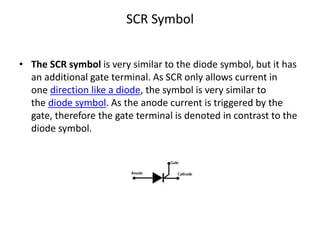
• The SCR symbol is very similar to the diode symbol, but it has
an additional gate terminal. As SCR only allows current in
one direction like a diode, the symbol is very similar to
the diode symbol. As the anode current is triggered by the
gate, therefore the gate terminal is denoted in contrast to the
diode symbol.
2. • The three terminals of the SCR are named anode, cathode,
and gate.
• For proper working, connect the anode of the SCR with
positive and cathode with negative of the battery.
• A positive pulse for a short duration is required at the gate to
kick start the conduction.
3. SCR Construction
• SCR has four layers of extrinsic semiconductor materials.
These four-layer form three PN junctions named J1, J2, and J3.
The layers are either NPNP or PNPN.
• The anode and cathode terminals are placed at the end layers
and where the gate terminal is placed with the third layer. The
outer layers are heavily dopped and the inner two layers are
lightly dopped.
• The SCR Construction is illustrated here below.
4 Layers of SCR Construction
4. SCR Working
SCR working depends upon the battery polarity and the gate
input. The SCR can operate in three different modes.
• Forward Blocking Mode
• Forward Conduction Mode
• Reverse Blocking Mode
5. Forward Blocking Mode of SCR
• When anode of SCR connects to the positive and cathode of SCR
with the negative of the battery terminal. And no pulse is applied at
the gate terminal. The SCR work in the forward blocking mode. This
means that SCR will not conduct even though the polarity of SCR is
forward bias.
• In forward blocking mode, the J1 and J3 PN junctions are forward
biased. But the middle junction J2 is reverse biased, therefore, the
SCR will not conduct in the forward blocking mode.
6. Forward Conduction Mode of SCR
• Forward conduction mode is the only mode of SCR for conduction.
• The SCR can be set into the forward conduction mode in two ways.
• First by providing the gate pulse to forward bias the J2 junction.
• Second by increasing the anode to cathode voltage to break down
the J2 junction.
• The gate pulse method is preferred and suitable for many
applications. The breakdown method reduces the SCR lifetime.
• The SCR will remain in conduction mode even after the removal of
the gate pulse or reducing the applied voltage.
• If the anode current of the SCR drops below the holding current the
SCR will stop falling back to forward blocking mode.
7. Reverse Blocking Mode in SCR
• If the anode terminal of the SCR connects to the negative and
cathode terminal of SCR connects to the positive of battery
terminals.
• The SCR is in reverse blocking mode. In this mode, J1 and J3
junctions are reverse biased.
• Where the middle junction J2 is forward bias.
• As two junctions are reverse bias, so there is no current
flowing through it but only a small leakage current due to the
drift charge carrier.
9. VI Characteristics of SCR
• The curve of VI characteristics of SCR is obtained by changing the voltage
across the SCR and noticing the current through SCR.
• When connecting in reverse polarity, the SCR will conduct a small current,
leakage current up to breakdown voltage, VBR. After that point, the SCR
will break down and start to act like a short circuit.
• Below the breakdown point, the region is called reverse blocking mode.
• When the voltage reaches the VBO point, the SCR starts the current flow.
• Alternatively, the SCR can be put into the forward conduction mode by
applying the gate that will increase the anode current above the latching
current.
• A higher gate current can put SCR faster in the forward conduction mode
as in the graph Ig3>Ig2>Ig1.
• The SCR will remain in the forward conduction mode if the anode current
is above the holding current.
10. SCR Applications
• The most common SCR application is the DC motor speed
control.
• The DC motor has two windings, where the armature
winding is connected to the AC supply by two SCR.
• The SCR controls the amount of current to the motor and
ultimately the speed of the DC motor.
11. SCR Clarifying Questions
1.What current need to trigger SCR?
• To fire or trigger SCR, a minimum anode current greater than
the latching current is required. The latching current is the
property of the SCR and can be found on the datasheet. The
latching current can be spotted on VI characteristics of SCR as
IL.
2.Is the heat sink of SCR the cathode or anode or trigger?
• The heat sink is normally connecting to the anode terminal of
the stud base SCR. To completely identify the terminals, use a
multimeter on ohms. The trigger or gate terminal and cathode
will show connectivity.
12. SCR Clarifying Questions
3. How to connect SCRs to get a higher working voltage?
• SCRs are connected in series for working in higher voltage and
improving the blocking capacity. The voltage distribution is
between the SCRs relates to the leakage current. Therefore,
appropriate adjustments are made for equal voltage distribution.
4. What is the difference between breakdown and the breakover
voltage in SCR?
• The breakdown voltage is the voltage limit for reverse blocking
mode, and it can be found on VBR on VI characteristics of SCR.
Similarly, the breakover voltage is the limit of the forward
blocking mode and it can be found as VBO on the VI characteristics
of SCR.
13. 5. How to turn off SCR?
The SCR will turn off automaticity in AC supply due to zero
crossing called neutral commutation. Where DC supply, anode
current must be reduced below the holding current to turn of
the SCR.
14. Mounting of SCR
• When the current passes through SCR is greater than the
rated value, the thermal stress produced in it which generates
mechanical force.
• If this mechanical force does not control, the SCR may
damaged.
• The protection of the SCR in such a condition is done by
proper mounting of it. The mounting method depends upon
the rating of the SCR.
15. 1.Lead mounting 2. Bolt mounting
3. Stud Mounting
1a. This method is used when load current is of small value.
1b.The SCR does not require cooling device or heat sink in this method
because most of the heat is dissipated by radiation and convection.
2a.There is one hole is provided in the SCR.
2b.The heat sink and SCR are joined by the bolt.
2c.The mica or fibre insulation is kept in between the heat sink and
SCR. This type of mounting is used in the small and medium rating SCR.
3a.There are two molybdenum plates kept on both sides of SCR.
3b.The anode is soldered with aluminium resulting one stud is created.
The SCR is joined to heat sink by this stud.
3c .If there is not necessary electrical isolation, mica or fibre type
washers are used.
3d.The conduction of heat is done easily though mica or fibre type
washers. It will also works as electrical insulator.