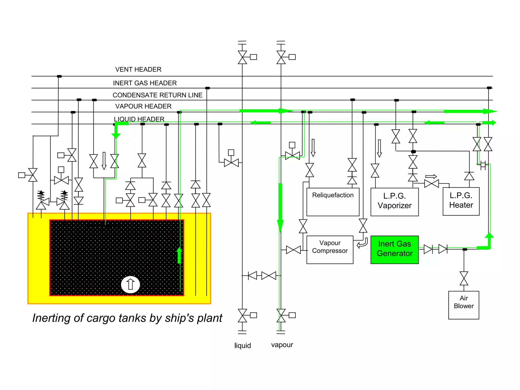
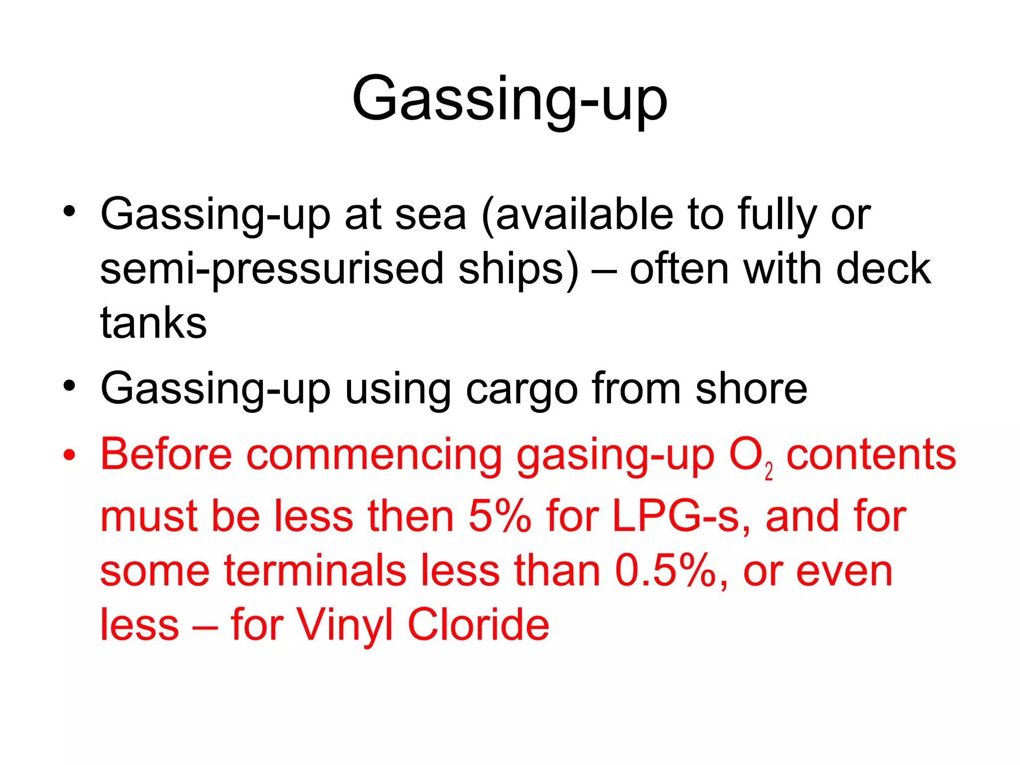
Best VIP Call Girls Noida Sector 40 Call Me: 8448380779
Lpg lng cargo_handling Merchant Shipping
1. LPG/LNG cargo handling
• Inerting (izlaz iz doka)
• Gassing-up
• Cooling-down (tanks)
• Loading
• Refrigiration (for LPG Carriers)
• Discharging
• Inerting (if changing cargo or aerating) (ulaz u
d.)
• Aerating (degazation)
2. Inerting
• By displacement method
• low speed of inert gas
• abt. 4 changing of tank volume
• entering of IG on top or bottom of tank (depending
of specific density)
• By mixing of inert gas and gas residues
• high speed of IG entering (mixing)
3. VENT HEADER
INERT GAS HEADER
CONDENSATE RETURN LINE
LIQUID HEADER
Reliquefaction
Vapour
Compressor
L.P.G.
Vaporizer
Inert Gas
Generator
L.P.G.
Heater
Air
Blower
VAPOUR HEADER
liquid vapour
Inerting by displacement method
4. VAPOUR HEADER
LIQUID HEADER
VENT HEADER
INERT GAS HEADER
CONDENSATE RETURN LINE
Reliquefaction
Vapour
Compressor
L.P.G.
Vaporizer
Inert Gas
Generator
L.P.G.
Heater
Air
Blower
liquid vapour
Inerting of cargo tanks by ship's plant
5. Gassing-up
• For passing fm.inerted to loaded condition
• Inert gas has uncondensable gases
(Nitrogen and CO2 can not be condensed
by ship’s reliquefaction plant)
• problem w. reliquifaction plant (condenser)
• Venting to atmosphere or return to shore
until tank is full with next cargo vapour
6. Gassing-up
• Gassing-up at sea (available to fully or
semi-pressurised ships) – often with deck
tanks
• Gassing-up using cargo from shore
• Before commencing gasing-up O2 contents
must be less then 5% for LPG-s, and for
some terminals less than 0.5%, or even
less – for Vinyl Cloride
8. CONDENSATE RETURN LINE
VENT HEADER
INERT GAS HEADER
LIQUID HEADER
Reliquefaction
Vapour
Compressor
L.P.G.
Vaporizer
Inert Gas
Generator
L.P.G.
Heater
Air
Blower
VAPOUR HEADER
liquid vapour
Gassing-up cargo tanks using liquid
fm. shore
9. VENT HEADER
INERT GAS HEADER
CONDENSATE RETURN LINE
LIQUID HEADER
Reliquefaction
Vapour
Compressor
L.P.G.
Vaporizer
Inert Gas
Generator
L.P.G.
Heater
Air
Blower
VAPOUR HEADER
liquid vapour
Gassing-up cargo tanks using vapour
fm. shore
10. Cooling-down
• For preventing excesive pressure during loading
or transporting
• Spraying cargo liquid into a tank at a slow rate –
evaporation/expansion
• Cooling-down rate depends of the tanks design
and size – abt. 10o
C per hour
• Inert gas – cargo vapour mixture goes to vent
riser (atmosphere) or reliquefaction plant
(problem with noncondensable gases – constant
condenser venting)
11. Cooling-down
• Cargo tank cooling-down reduces temperature into
hold space or interbarrier spaces – pressure drop
• Pressure drop into interbarrier or hold space should
be compensated with inert gas or dry air
• During coolin-down water (moisture) or remain inert
gas could couse big problems (pumps, valves and
other equipment could stuck up)
12. LIQUID HEADER
VENT HEADER
INERT GAS HEADER
CONDENSATE RETURN
LINE
Reliquefaction
Vapour
Compressor
L.P.G.
Vaporizer
Inert Gas
Generator
L.P.G.
Heater
Air
Blower
VAPOUR HEADER
liquid vapour
Cool-down using liquid from shore:
vapour returned to shore
13. Loading the cargo
before
• Ship / shore preloading plan
• Cargo characteristics, inhibitors and inert
gas to be used
• Before loading attention to be paid:
• safety valves settings and h.p. alarm settings
• remotely operated valves
• reliquefaction equipment
• gas detection system
• alarms and controls
• ESD (Emergency Shut Down)
14. Loading
• Vapourisation control (LPG ships):
• vapour return line connected to gas compressor
• reliquefaction plant – liquid return to tanks
• combination of above
• Vapourisation control (LNG ships):
• return to shore is normal procedure (no reliq. plant)
• return by ship’s compressors or compressors from
shore – max. loading rate limitation
15. VAPOUR HEADER
LIQUID HEADER
VENT HEADER
INERT GAS HEADER
CONDENSATE RETURN LINE
Reliquefaction
Vapour
Compressor
L.P.G.
Vaporizer
Inert Gas
Generator
L.P.G.
Heater
Air
Blower
liquid vapour
Loading with vapur return to shore
16. VAPOUR HEADER
LIQUID HEADER
VENT HEADER
INERT GAS HEADER
CONDENSATE RETURN LINE
Reliquefaction
Vapour
Compressor
L.P.G.
Vaporizer
Inert Gas
Generator
L.P.G.
Heater
Air
Blower
liquid vapour
Loading without vapour return
17. Loading fully refrigirated ships
• Usually from fully refrigirated storage (jetty)
• Long distance btw. shore storage and ship
and high ambient temperature can couse
tank pressure remaining problem, specially
in early stages;
• loading rate must be reduced to give a time reliq.
plant for cooling down cargo tank
• loading limited quantities of liquid into the tank via
the top sprays – helping condensate some cargo
18. Loading pressurised ships
• Arriving at a loading terminal at atmospheric
pressure
• Need vapour from shore to purge remaining
nitrogen or contaminants from tanks –
equalise pressures btw. ship and terminal
• Tank and pipeline temperature must not fall
bellow design temperature – slow rate at the
beginning
19. Loading pressurised ships from
refrigirated storage
• Tanks suitable for min. temperature btw. 0 and –5o
C
• Cargo should be heated (pumping through cargo heater
on board or shore)
• Attention to be paid for topping of (max. 98% at max.
temperature reached during the voyage)
20. Loading semi-pressurised ships from
refrigirated storage
• Cargo tanks constructed of low temperature
steels – able to accomodate fully refrigirated
propan (-40 and –50o
C) or for ethylene -104o
C
• Refrigirated cargo can be loaded without heating
• Cargo temperature can be maintained during
loaded voyage by reliq. plant – if discharged to
refrigirated storage
• Cargo can be heated during loaded voyage if
discharged into pressurised facilities
21. VENT HEADER
INERT GAS HEADER
CONDENSATE RETURN LINE
LIQUID HEADER
Reliquefaction
Vapour
Compressor
L.P.G.
Vaporizer
Inert Gas
Generator
L.P.G.
Heater
Air
Blower
VAPOUR HEADER
liquid vapour
Cargo refrigiration at sea
22. Cargo refrigiration at sea
• By reliquefaction plant
• Compressor should not be run during heavy
rolling
• Condensate is passed through the top sprayes –
cooling down the liquid surface (the bulk of the
liquid has not been cooled)
• To cool down bulk of the liquid condensate
return should be through the bottom connection
of the tank to ensure proper circulation
23. Cargo refrigiration at sea
• Reliquefaction plant run on more than one
tank simultaneosly – carefully controled
condensate return (to avoid overfilling of
any one tank)
24. VENT HEADER
INERT GAS HEADER
CONDENSATE RETURN LINE
LIQUID HEADER
Reliquefaction
Vapour
Compressor
L.P.G.
Vaporizer
Inert Gas
Generator
L.P.G.
Heater
Air
Blower
VAPOUR HEADER
liquid vapour
Discharge without vapour return
25. Discharging
• Method depends on type of ship, cargo
specification and terminal storage;
• Discharge by pressurising the vapour space
– shore vapor suply or vaporiser and compressor on board
• Discharge with or without booster pumps
– discharging limited by pipeline diametar
– booster pump – for long distances or higher levels
• Discharge via booster pump and cargo heater
– when discharged from refrigirated ship to pressurised
terminals
26. VENT HEADER
INERT GAS HEADER
CONDENSATE RETURN LINE
LIQUID HEADER
Reliquefaction
Vapour
Compressor
L.P.G.
Vaporizer
Inert Gas
Generator
L.P.G.
Heater
Air
Blower
VAPOUR HEADER
liquid vapour
Discharge with vapour return
27. After discharge
• Draining tanks and pipelines
• Pump discharge valve should not be throtteled for
flow control if the pump is operating with a booster
pump (can damage pump)
• Cargo must be drained from all deck lines and
cargo hoses or hard arms – by compressor (from
ship to shore) or by blowing the liquid into ship’s
tanks using nitrogen injected at the base or apex of
the hard arm
• Only after depressuring all deck lines and purging
with nitrogen ship/shore connection can be broken
28. liquid vapour
CONDENSATE RETURN LINE
VENT HEADER
INERT GAS HEADER
LIQUID HEADER
Reliquefaction
Vapour
Compressor
L.P.G.
Vaporizer
Inert Gas
Generator
L.P.G.
Heater
Air
Blower
VAPOUR HEADER
Aeration of cargo tanks
29. Ballast voyage
• Small quantity of cargo retain on bord (heel)
• only if the same grade of cargo will be loaded
• For large LNG carriers 2000 to 3000 m3
may
be retained in the tanks – fitted with spray
cool-down pumps in each cargo tank to
minimise tank thermal gradients
• On LPG-s small amount of liquid remaining
to provide necessary cooling during ballast
voyage – by using reliquefaction plant
30. Amonia – special procedures
• When changing from amonia to LPG most traces of vapours
must be removed (remaining volume quantity - 20ppm)
• Amonia – when evaporating to air is particulary likely to
reach super-cooled condition – all liquid must be removed
• For amonia the inert gas plant must not be used as the
ship’s inert gas plant is not suitable – carbamate formation
• Blowing warm fresh air into system – disperzing amonia
vapour
• Sometimes washing with fresh water (amonia is highly water
soluble) – not suitable for prismatic tanks (for tanks with
minimum internal structure - full drainage, clean and rust
free tanks)
31. Amonia – special procedures
• All traces of water must be removed (preventing
formation of ice or hydrats) – fixed or portable pumps
• High solubility of amonia in water (300:1) can lead to
dangerous vacum condition in tank – to ensure essential
air entry into the tank during water washing proces – air
dew point must be lower than the tank atmosphere