1. CIRCUIT
IDEAS
DICE WITH 7-SEGMENT DISPLAY
EFY LAB CD4026, pin 14 (cascading output) is
to be left unused (open), but in case of IVEDI
S.C. DW
A
digital dice circuit can be eas- CD4033, pin 14 serves as lamp test pin
ily realised using an astable and the same is to be grounded.
oscillator circuit followed by The circuit uses only a handful of
a counter, display driver and a dis- components. Its power consumption is
play. also quite low because of use of CMOS astable oscillator configured around
Here we have used a timer NE555 ICs, and hence it is well suited for bat- IC1 as well as capacitor C1 (through
as an astable oscillator with a fre- tery operation. In this circuit two tac- resistor R1), which charges to the bat-
quency of about 100 Hz. Decade tile switches S1 and S2 have been pro- tery voltage. Thus even after switch
counter IC CD4026 or CD4033 (which- vided. While switch S2 is used for ini- S1 is released, the astable circuit
ever available) can be used as counter- tial resetting of the display to ‘0,’ de- around IC1 keeps producing the clock
cum-display driver. When using pression of S1 simulates throwing of until capacitor C1 discharges suffi-
ciently. Thus for du-
ration of depression
of switch S1 and dis-
charge of capacitor
C1 thereafter, clock
pulses are produced
by IC1 and applied to
clock pin 1 of counter
IC2, whose count ad-
vances at a frequency
of 100 Hz until C1
discharges suffi-
ciently to deactivate
IC1.
When the oscilla-
tions from IC1 stop,
the last (random)
count in counter IC2
can be viewed on the
7-segment display.
This count would
normally lie between
0 and 6, since at the
leading edge of every
the dice by a player. 7th clock pulse, the counter is reset to
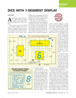
Decoded Segment Outputs When battery is con- zero. This is achieved as follows.
for Counts 0 through 9 nected to the circuit, the Observe the behavior of ‘b’ seg-
counter and display section ment output in the Table. On reset, at
around IC2 (CD4026/4033) count 0 until count 4, the segment ‘b’
is energised and the display output is high. At count 5 it changes
would normally show ‘0’, as to low level and remains so during
no clock input is available. count 6. However, at start of count 7,
Should the display show the output goes from low to high state.
any other decimal digit, you A differentiated sharp high pulse
may press re-set switch S2 through C-R combination of C4-R5 is
so that display shows ‘0’. To applied to reset pin 15 of IC2 to reset
simulate throwing of dice, the output to ‘0’ for a fraction of a
the player has to press pulse period (which is not visible on
switch S1, briefly. This ex- the 7-segment display). Thus, if the
tends the supply to the clock stops at seventh count, the dis-
WWW.EFYMAG.COM ELECTRONICS FOR YOU • NOVEMBER 2007 • 97
2. CIRCUIT
IDEAS
play will read zero. There is a prob- other chance until the display is non- the counter by ‘1,’ the same makes the
ability of one chance in seven that dis- zero. circuit somewhat complex and there-
play would show ‘0.’ In such a situa- Note. Although it is quite feasible fore such a modification has not been
tion, the concerned player is given an- to inhibit display of ‘0’ and advance attempted.
98 • NOVEMBER 2007 • ELECTRONICS FOR YOU WWW.EFYMAG.COM