1. INTEGRATED INVERTER/CONVERTER CIRCUIT AND CONTROL TECHNIQUE OF
MOTOR DRIVES WITH DUAL MODE CONTROL FOR EV/HEV APPLICATIONS
B.TECH (EEE) 1 TNRITS
CHAPTER-1
INTRODUCTION
1.1 INTRODUCTION
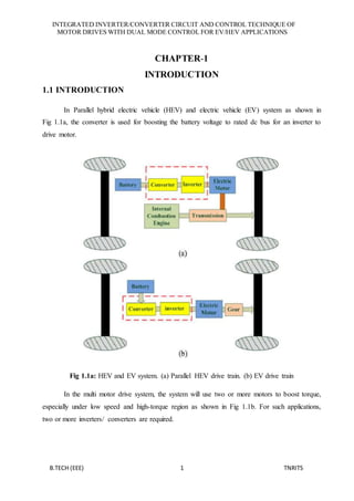
In Parallel hybrid electric vehicle (HEV) and electric vehicle (EV) system as shown in
Fig 1.1a, the converter is used for boosting the battery voltage to rated dc bus for an inverter to
drive motor.
Fig 1.1a: HEV and EV system. (a) Parallel HEV drive train. (b) EV drive train
In the multi motor drive system, the system will use two or more motors to boost torque,
especially under low speed and high-torque region as shown in Fig 1.1b. For such applications,
two or more inverters/ converters are required.
2. INTEGRATED INVERTER/CONVERTER CIRCUIT AND CONTROL TECHNIQUE OF
MOTOR DRIVES WITH DUAL MODE CONTROL FOR EV/HEV APPLICATIONS
B.TECH (EEE) 2 TNRITS
Fig 1.1b: Conventional multi motor drive system of EV/HEV.
Fig 1.1c shows the application of the proposed integrated circuit for motor drives with
dual-mode control for EV/HEV applications. As shown in Fig 1.1c, the proposed integrated
circuit allows the permanent magnet synchronous motor (PMSM) to operate in motor mode or
acts as boost inductors of the boost converter, and thereby, boosting the output torque coupled to
the same transmission system or dc-link voltage of an inverter connected to the output of the
integrated circuit. In motor mode, the proposed integrated circuit acts as an inverter and it
becomes a boost-type boost converter, while using the motor windings as the boost inductors to
boost the converter output voltage. Therefore, the proposed integrated circuit can significantly
reduce the volume and weight of the system.
Fig 1.1c: Proposed integrated inverter/converter for the multi motor drive system of EV/HEV.
3. INTEGRATED INVERTER/CONVERTER CIRCUIT AND CONTROL TECHNIQUE OF
MOTOR DRIVES WITH DUAL MODE CONTROL FOR EV/HEV APPLICATIONS
B.TECH (EEE) 3 TNRITS
Fig 1.1d: Boost converter with and without interleaved control.
(a) Single-phase boost converter. (b) Interleaved boost converter.
The integrated circuit presented in this project can act as an inverter and a boost converter
depending on the operation mode. For the integrated circuit, it not only can reduce the volume
and weight but also boost torque and dc-link voltage for motor/converter modes, respectively.
Moreover, a new control technique for the proposed integrated circuit under boost converter
mode is proposed to increase the efficiency. For conventional circuit, shown in Fig 1.1d (a) and
(b), a single phase boost converter has been widely used for boost control due to its simplicity.
However, for higher power applications, an interleaved boost converter can reduce the current
ripple and components stress and thereby reducing the losses and thermal stress. Based upon the
interleaved control idea, a boost-control technique using motor windings as boost inductors for
the proposed integrated circuit will be proposed. Under light load, the integrated circuit acts as a
single-phase boost converter for not invoking additional switching and conduction losses, and
functions as the two-phase interleaved boost converter under heavy load to significantly reduce
the current ripple and thereby reducing the losses and thermal stress.
4. INTEGRATED INVERTER/CONVERTER CIRCUIT AND CONTROL TECHNIQUE OF
MOTOR DRIVES WITH DUAL MODE CONTROL FOR EV/HEV APPLICATIONS
B.TECH (EEE) 4 TNRITS
Fig 1.1e: Integrated circuit for dual mode of motor drives and boost converter.
Fig 1.1f: Single-phase boost mode. (a) Charge path for inductor.
(b) Discharge path for inductor
Therefore, the proposed control technique for the proposed integrated circuit under boost
converter mode can increase the efficiency.
5. INTEGRATED INVERTER/CONVERTER CIRCUIT AND CONTROL TECHNIQUE OF
MOTOR DRIVES WITH DUAL MODE CONTROL FOR EV/HEV APPLICATIONS
B.TECH (EEE) 5 TNRITS
CHAPTER-2
DC-DC CONVERTERS
2.1 INTRODUCTION
A DC–DC converter with a high step-up voltage gain is used for many applications, such
as high-intensity discharge lamp ballasts for automobile headlamps, fuel cell energy conversion
systems, solar-cell energy conversion systems and battery backup systems for uninterruptible
power supplies. Theoretically, a dc–dc boost converter can achieve a high step-up voltage gain
with an extremely high duty ratio. However, in practice, the step-up voltage gain is limited due
to the effect of power switches, rectifier diodes and the equivalent series resistance (ESR) of
inductors and capacitors.
In general, a conventional boost converter can be adopted to provide a high step-up
voltage gain with a large duty ratio. However, the conversion efficiency and the step-up voltage
gain are limited due to the constraints of the losses of power switches and diodes, the equivalent
series resistance of inductors and capacitors and the reverse recovery problem of diodes.
However, the active switch of these converters will suffer very high voltage stress and high
power dissipation due to the leakage inductance of the transformer. To reduce the Voltage spike,
a resistor–capacitor–diode snubber can be employed to limit the voltage stress on the active
switch. However, the efficiency will be reduced. High step-up converters with a low input
current ripple based on the coupled inductor have been developed. The low input current ripple
of these converters is realized by using an additional LC circuit with a coupled inductor.
However, leakage inductance issues that relate to the voltage spike and the efficiency
remain significant. An integrated boost–fly back converter based on a coupled inductor with high
efficiency and high step-up voltage gain has been presented. The energy stored in the leakage
inductor is recycled into the output during the switch off period. Thus, the efficiency can be
increased and the voltage stress on the active switch can be suppressed. Many step-up
converters, which use an output voltage stacking to increase the voltage gain, are presented.
6. INTEGRATED INVERTER/CONVERTER CIRCUIT AND CONTROL TECHNIQUE OF
MOTOR DRIVES WITH DUAL MODE CONTROL FOR EV/HEV APPLICATIONS
B.TECH (EEE) 6 TNRITS
High Step-
up DC-DC
Front END
DC-AC
Inverters
Low Voltage
DC Bus
+
-
VFc Vac
+
-
+
-
24-40VDC 380-400VDC
High Voltage
DC Bus
VDC
Fig 2.1: General Power generation system with a high step-up converter
A high step-up dc–dc converter is shown in Fig.2.1 with an integrated coupled inductor
and a common mode electromagnetic interference reduction filter. Here a specific back converter
with a coupled inductor and an output voltage stacking is developed. A high step-up converter,
which utilizes a coupled inductor and a voltage doubler technique on the output voltage stacking
to achieve a high step-up voltage gain, is introduced. A high step-up boost converter that uses
multiple coupled inductors for the output voltage stacking is proposed.
Additionally, step-up converters, which use a voltage lift, are introduced. Since the
switch must suffer high current during the switch on period, this technique is appropriate for
low-output-power applications. Since the low voltage rating and the low conducting resistance
RDS (on) of the power switch are used for these converters, the high conversion efficiency can be
achieved. However, the requirement for a coupled inductor with a high coupling coefficient will
result in manufacturing difficulty and cost increment. A high step-up converter, which uses a
three state switching cell and a voltage multiplier stage based on capacitors, can achieve high
step-up gain.
Power engineering is the method used to supply electrical energy from a source to its
users. It is of vital importance to industry. It is likely that the air we breathe and water we drink
are taken for granted until they are not there. Energy conversion technique is the main focus of
power engineering. The corresponding equipment can be divided into four groups:
AC/AC transformer
AC/DC rectifier
DC/DC converter
DC/AC inverter
7. INTEGRATED INVERTER/CONVERTER CIRCUIT AND CONTROL TECHNIQUE OF
MOTOR DRIVES WITH DUAL MODE CONTROL FOR EV/HEV APPLICATIONS
B.TECH (EEE) 7 TNRITS
Grid interconnection of PV/FC system requires power converters to meet the grid
requirements like voltage amplitude, frequency, and phase angle. First convert the low voltage
dc into high voltage dc by using boost dc-dc converter and then convert this dc voltage into ac by
using inverters and finally connect the whole system to grid. This type of system (dc-dc and dc-
ac conversion) is called two stage conversion systems.
DC-DC converters are electronic devices used whenever we want to change DC electrical
power efficiently from one voltage level to another. They are needed because unlike AC, DC
cannot simply be stepped up or down using a transformer. In many ways, a DC-DC converter is
the equivalent of a transformer.
The dc-dc converters can be viewed as dc transformer that delivers a dc voltage or
current at a different level than the input source. Electronic switching performs this dc
transformation as in conventional transformers and not by electromagnetic means. The dc-dc
converters find wide applications in regulated switch-mode dc power supplies and in dc motor
drive applications.
DC-DC converters are non-linear in nature. The design of high performance control for
them is a challenge for both the control engineering engineers and power electronics engineers.
In general, a good control for dc-dc converter always ensures stability in arbitrary operating
condition. Moreover, good response in terms of rejection of load variations, input voltage
changes and even parameter uncertainties is also required for a typical control scheme.
After pioneer study of dc-dc converters, a great deal of efforts has been directed in
developing the modaling and control techniques of various dc-dc converters. Classic linear
approach relies on the state averaging techniques to obtain the state-space averaged equations.
From the state-space averaged model, possible perturbations are introduced into the state
variables around the operating point. On the basis of the equations, transfer functions of the
open-loop plant can be obtained. A linear controller is easy to be designed with these necessary
transfer functions based on the transfer function.
DC to DC converters are important in portable electronic devices such as cellular phones
and laptop computers, which are supplied with power from batteries primarily. Such electronic
devices often contain several sub-circuits, each with its own voltage level requirement different
than that supplied by the battery or an external supply (sometimes higher or lower than the
supply voltage, and possibly even negative voltage). Additionally, the battery voltage declines as
its stored power is drained. Switched DC to DC converters offer a method to increase voltage
8. INTEGRATED INVERTER/CONVERTER CIRCUIT AND CONTROL TECHNIQUE OF
MOTOR DRIVES WITH DUAL MODE CONTROL FOR EV/HEV APPLICATIONS
B.TECH (EEE) 8 TNRITS
from a partially lowered battery voltage thereby saving space instead of using multiple batteries
to accomplish the same thing.
DC-DC converters are electronic devices that are used whenever we want to change DC
electrical power efficiently from one voltage level to another. In the previous chapter we
mentioned the drawbacks of doing this with a linear regulator and presented the case for SMPS.
Generically speaking the use of a switch or switches for the purpose of power conversion can be
regarded as a SMPS. From now onwards whenever we mention DC-DC Converters we shall
address them with respect to SMPS.
A few applications of interest of DC-DC converters are where 5V DC on a personal
computer motherboard must be stepped down to 3V, 2V or less for one of the latest CPU chips;
where 1.5V from a single cell must be stepped up to 5V or more, to operate electronic circuitry.
In all of these applications, we want to change the DC energy from one voltage level to another,
while wasting as little as possible in the process. In other words, we want to perform the
conversion with the highest possible efficiency.
2.2 TYPES OF DC-DC CONVERTERS
There are many different types of DC-DC converters, each of which tends to be more
suitable for some type of applications than for others. For convenience they can be classified into
various groups, however. For example some converters are only suitable for stepping down the
voltage, while others are only suitable for stepping it up a third group can be used for either. In
this we are going to main types of DC-DC converters.
Currently DC-DC converters can be divided into two types.
Non-isolated dc-dc converters
Isolated dc-dc converters
2.3 NON-ISOLATED DC-DC CONVERTERS
The non-isolated converter usually employs an inductor, and there is no dc voltage
isolation between the input and the output. The vast majority of applications do not require dc
isolation between its input and output voltages. The non-isolated dc-dc converter has a dc path
between its input and output. Battery-based systems that don’t use the ac power line represent a
major application for non-isolated dc-dc converters. Point-of-load dc-dc converters that draw
input power from an isolated dc-dc converter, such as a bus converter, represent another widely
used non-isolated application.
9. INTEGRATED INVERTER/CONVERTER CIRCUIT AND CONTROL TECHNIQUE OF
MOTOR DRIVES WITH DUAL MODE CONTROL FOR EV/HEV APPLICATIONS
B.TECH (EEE) 9 TNRITS
Most of these dc-dc converter ICs use either an internal or external synchronous rectifier.
Their only magnetic component is usually an output inductor and thus less susceptible to
generating electromagnetic interference. For the same power and voltage levels, it usually has
lower cost and fewer components while requiring less pc-board area than an isolated dc-dc
converter. For lower voltages non-isolated buck converters can be used.
There are five main types of converter in this non-isolating group they are
Buck Converter
Boost Converter
Buck-Boost Converter
Cuk Converter
The Buck converter is used for voltage step-down reduction, while the Boost converter is
used for voltage step-up. The Buck-Boost and Cuk converters can be used for either step-down
or step-up, but are essentially voltage polarity reversers or ‘inverters’. The Charge-pump
converter is used for either voltage step-up or voltage inversion, but only in relatively low power
applications.
2.4 BOOST CONVERTER
A boost converter (step-up converter) is a DC-to-DC power converter with an output
voltage greater than its input voltage. It is a class of switched- mode power supply (SMPS)
containing at least two semiconductor switches (a diode and a transistor) and at least one energy
storage element, a capacitor, inductor, or the two in combination. Filters made of capacitors
(sometimes in combination with inductors) are normally added to the output of the converter to
reduce output voltage ripple.
LOAD
SUPPLY
Fig 2.4: the basic schematic of a boost converter
10. INTEGRATED INVERTER/CONVERTER CIRCUIT AND CONTROL TECHNIQUE OF
MOTOR DRIVES WITH DUAL MODE CONTROL FOR EV/HEV APPLICATIONS
B.TECH (EEE) 10 TNRITS
Power for the boost converter can come from any suitable DC sources, such as batteries,
solar panels, rectifiers and DC generators. A process that changes one DC voltage to a different
DC voltage is called DC to DC conversion. A boost converter is a DC-to-DC converter with an
output voltage greater than the source voltage. A boost converter is sometimes called a step-up
converter since it “steps up” the source voltage. Since power (P=VI) must be conversed, the
output current is lower than the source current.
2.4.1 HISTORY
For high efficiency, the SMPS switch must turn on and off quickly and have low losses.
The advent of a commercial semiconductor switch in the 1950s represented a major milestone
that made SMPSs such as the boost converter possible. The major DC to DC converters were
developed in the early 1960s when semiconductor switches had become available. The aero
scope industry’s need for small, lightweight, and efficient power converters led to the converter’s
rapid development.
Switched systems such as SMPS are a challenge to design since its model depends on
whether a switch is opened or closed. R. D. Middle brook from Caltech in 1977 published the
models for DC to DC converters used today. Middle brook averaged the circuit configurations
for each switch state in a technique called state-space averaging. This simplification reduced two
systems into one. The new model led to insightful design equations which helped SMPS growth.
2.4.2 APPLICATIONS
Battery powered systems often stack cells in series to achieve higher voltage. However,
sufficient stacking of cells is not possible in many high voltage applications due to lack of space.
Boost converters can increase the voltage and reduce the number of cells. Two battery
powered applications that use boost converters are hybrid electric vehicles (HEV) and lighting
systems.
A boost converter is used as the voltage increase mechanism in the circuit known as the
‘Joule thief’. This circuit topology is used with low power battery applications, and is aimed at
the ability of a boost converter to 'steal' the remaining energy in a battery. This energy would
otherwise be wasted since the low voltage of a nearly depleted battery makes it unusable for a
normal load. This energy would otherwise remain untapped because many applications do not
allow enough current to flow through a load when voltage decreases. This voltage decrease
occurs as batteries become depleted, and is a characteristic of the ubiquitous alkaline battery.
11. INTEGRATED INVERTER/CONVERTER CIRCUIT AND CONTROL TECHNIQUE OF
MOTOR DRIVES WITH DUAL MODE CONTROL FOR EV/HEV APPLICATIONS
B.TECH (EEE) 11 TNRITS
Since (𝑃 = 𝑉2
/𝑅) as well, and R tends to be stable, power available to the load goes down
significantly as voltage decreases.
2.4.3 OPERATING PRINCIPLE
The key principle that drives the boost converter is the tendency of an inductor to resist
changes in current. In a boost converter, the output voltage is always higher than the input
voltage. A schematic of a boost power stage When the switch is closed, current flows through
the inductor, which stores energy from the current in a magnetic field. During this time, the
switch acts like a short circuit in parallel with the diode and the load, so no current flows to the
right hand side of the circuit.
When the switch is opened, the short circuit is removed and the load is back in play in the
circuit. This represents a sudden increase in the impedance of the circuit, which, by Ohm’s law
will demand either a decrease in current, or an increase in voltage. The inductor will tend to
resist such a sudden change in the current, which it does by acting as a voltage source in series
with the input source, thus increasing the total voltage seen by the right hand side of the circuit
and thereby preserving (for a brief moment) the current level that was seen when the switch was
closed. This is done using the energy stored by the inductor. Over time, the energy stored in the
inductor will discharge into the right hand side of the circuit, bringing the net voltage back down.
If the switch is cycled fast enough, the inductor will not discharge fully in between
charging stages, and the load will always see a voltage greater than that of the input source alone
when the switch is opened. Also while the switch is opened, the capacitor in parallel with the
load is charged to this combined voltage.
When the switch is then closed and the right hand side is shorted out from the left hand
side, the capacitor is therefore able to provide the voltage and energy to the load. During this
time, the blocking diode prevents the capacitor from discharging through the switch. The switch
must of course be opened again fast enough to prevent the capacitor from discharging too much.
The basic principle of a Boost converter consists of 2 distinct states.In the On-state, the switch S
is closed, resulting in an increase in the inductor current.
In the Off-state, the switch is open and the only path offered to inductor current is
through the fly back diode D, the capacitor C and the load R. This result in transferring
the energy accumulated during the On-state into the capacitor.
The input current is the same as the inductor current as can be seen.So it is not
discontinuous as in the buck converter and the requirements on the input filter are relaxed
compared to a buck converter
12. INTEGRATED INVERTER/CONVERTER CIRCUIT AND CONTROL TECHNIQUE OF
MOTOR DRIVES WITH DUAL MODE CONTROL FOR EV/HEV APPLICATIONS
B.TECH (EEE) 12 TNRITS
Vi
L
IL ID
D
S
Is
Vs C R V0
Fig 2.4.3a: over all diagram of Boost converter
Fig 2.4.3b: the two configuration of boost converter depending on the
state of the switch S Continuous mode
When a boost converter operates in continuous mode, the current through the inductor
(IL) never falls to zero. the typical waveforms of currents and voltages in a converter operating in
this mode. The output voltage can be calculated as follows, in the case of an ideal converter (i.e.
using components with an ideal behaviour) operating in steady conditions.
13. INTEGRATED INVERTER/CONVERTER CIRCUIT AND CONTROL TECHNIQUE OF
MOTOR DRIVES WITH DUAL MODE CONTROL FOR EV/HEV APPLICATIONS
B.TECH (EEE) 13 TNRITS
Fig 2.4.3c: Waveforms of current and voltage in
a boost converter operating in continuous mode
During the On-state, the switch S is closed, which makes the input voltage (Vi) appear
across the inductor, which causes a change in current (IL) flowing through the inductor during a
time period (t) by the formula:
∆𝐼𝐿
∆𝑡
=
𝑉𝑖
𝐿
(1.1)
At the end of the On-state, the increase of IL is therefore:
∆𝐼𝐿𝑜𝑛 =
1
𝐿
∫ 𝑉𝑖 𝑑𝑡
𝐷𝑇
0
=
𝐷𝑇
𝐿
𝑉𝑖 (1.2)
D is the duty cycle. It represents the fraction of the commutation period T during which the
switch is ON. Therefore D ranges between 0 (S is never on) and 1 (S is always on).
During the Off-state, the switch S is open, so the inductor current flows through the load. If we
consider zero voltage drop in the diode, and a capacitor large enough for its voltage to remain
constant, the evolution of IL is:
𝑉𝑖 − 𝑉0 = 𝐿
𝑑𝐼 𝐿
𝑑𝑡
(1.3)
Therefore, the variation of IL during the Off-period is:
∆𝐼𝐿𝑜𝑓𝑓 = ∫
( 𝑉𝑖 −𝑉0 ) 𝑑𝑡
𝐿
𝑇
𝐷𝑇
=
( 𝑉𝑖 −𝑉0)(1−𝐷) 𝑇
𝐿
(1.4)
14. INTEGRATED INVERTER/CONVERTER CIRCUIT AND CONTROL TECHNIQUE OF
MOTOR DRIVES WITH DUAL MODE CONTROL FOR EV/HEV APPLICATIONS
B.TECH (EEE) 14 TNRITS
As we consider that the converter operates in steady-state conditions, the amount of
energy stored in each of its components has to be the same at the beginning and at the end of a
commutation cycle. In particular, the energy stored in the inductor is given by:
𝐸 =
1
2
𝐿𝐼𝐿
2
(1.5)
So, the inductor current has to be the same at the start and end of the commutation cycle. This
means the overall change in the current (the sum of the changes) is zero:
∆𝐼𝐿𝑜𝑛 + ∆𝐼𝐿𝑜𝑓𝑓 = 0 (1.6)
Substituting ∆ILON and ∆ILOFFby their expressions yields:
∆𝐼𝐿𝑜𝑛 + ∆𝐼𝐿𝑜𝑓𝑓 =
𝑉𝑖 𝐷𝑇
𝐿
+
( 𝑉𝑖 −𝑉0 )(1−𝐷) 𝑇
𝐿
= 0 (1.7)
This can be written as:
𝑉0
𝑉𝑖
=
1
1−𝐷
(1.8)
This in turn reveals the duty cycle to be:
𝐷 = 1 −
𝑉𝑖
𝑉0
(1.9)
The above expression shows that the output voltage is always higher than the input
voltage (as the duty cycle goes from 0 to 1), and that it increases with D, theoretically to infinity
as D approaches 1. This is why this converter is sometimes referred to as a step-up converter.
Fig2.4.3d: Waveforms of current and voltage in a boost
converter operating in discontinuous mode
15. INTEGRATED INVERTER/CONVERTER CIRCUIT AND CONTROL TECHNIQUE OF
MOTOR DRIVES WITH DUAL MODE CONTROL FOR EV/HEV APPLICATIONS
B.TECH (EEE) 15 TNRITS
If the ripple amplitude of the current is too high, the inductor may be completely
discharged before the end of a whole commutation cycle. This commonly occurs under light
loads. In this case, the current through the inductor falls to zero during part of the period (see
waveforms in figure 1.6). Although slight, the difference has a strong effect on the output
voltage equation. It can be calculated as follows:
As the inductor current at the beginning of the cycle is zero, its maximum value 𝐼𝐿𝑀𝑎𝑥 (at t=DT)
is
𝐼𝐿𝑀𝑎𝑥 =
𝑉𝑖 𝐷𝑇
𝐿
(1.10)
During the off-period, IL falls to zero after δT:
𝐼𝐿𝑀𝑎𝑥 +
(𝑉𝑖 −𝑉0 )𝛿𝑇
𝐿
= 0 (1.11)
Using the two previous equations, δ is:
𝛿 =
𝑉𝑖 𝐷
𝑉0 −𝑉𝑖
(1.12)
The load current Io is equal to the average diode current (ID). As can be seen on figure
1.6, the diode current is equal to the inductor current during the off-state. Therefore the output
current can be written as:
𝐼0 = 𝐼 𝐷
̅ =
𝐼 𝐿𝑀𝑎 𝑥
2
𝛿 (1.13)
Replacing ILmax and δ by their respective expressions yields:
𝐼0 =
𝑉𝑖 𝐷𝑇
2𝐿
.
𝑉𝑖 𝐷
𝑉0−𝑉𝑖
=
𝑉𝑖
2
𝐷2
𝑇
2𝐿(𝑉0−𝑉𝑖 )
(1.14)
Therefore, the output voltage gain can be written as follows:
𝑉0
𝑉𝑖
= 1 +
𝑉𝑖 𝐷2
𝑇
2𝐿 𝐼0
(1.15)
Compared to the expression of the output voltage for the continuous mode, this
expression is much more complicated. Furthermore, in discontinuous operation, the output
voltage gain not only depends on the duty cycle, but also on the inductor value, the input voltage,
the switching frequency, and the output current.
16. INTEGRATED INVERTER/CONVERTER CIRCUIT AND CONTROL TECHNIQUE OF
MOTOR DRIVES WITH DUAL MODE CONTROL FOR EV/HEV APPLICATIONS
B.TECH (EEE) 16 TNRITS
2.5 INTERLEAVED BOOST CONVERTER
Interleaved power converters can be very beneficial for high performance electrical
equipment applications. Reductions in size and electromagnetic emission along with an increase
in efficiency, transient response, and reliability are among the many advantages to using such
converters. Studies of interleaved DC-DC boost converters, which were performed by members
of the Power, Energy, and Thermal Division of the Air Force Research Laboratory’s (AFRL)
Propulsion Directorate, included theoretical derivations and simulations, and experimental
demonstrations. The experimental results clearly showed that interleaved designs can provide
significant benefit when utilized for high temperature and high power applications. In addition to
the electrical performance benefits, it was also demonstrated that coupled inductor interleaved
boost converters can be smaller and lighter compared to conventional converter topologies.
These study results have been organized and published as several technical papers during the
course of this project. In this technical report, the cumulative interleaved coupled inductor DC-
DC converter studies are summarized.
In response to these increasingly demanding electrical equipment power density
requirements, interleaved buck and boost converters have been studied in recent years for their
potential to improve power converter performance in terms of efficiency, size, conducted
electromagnetic emission, and transient response. Figure 2.5 shows a conventional DC-DC boost
converter circuit, consisting of an inductor, switch, diode, and capacitor configured in parallel to
a resistive load. The inductance of inductor (L1) is L. For continuous current conduction mode
(CCM) operation, the voltage gain between input and output voltages is given by Equation (1),
where D is the duty ratio of switch S1.
Fig 2.5: Conventional DC-DC Boost Converter Topology
𝑉𝑜𝑢𝑡
𝑉𝑖𝑛
⁄ = 1
(1 − 𝐷)⁄ (1.16)
17. INTEGRATED INVERTER/CONVERTER CIRCUIT AND CONTROL TECHNIQUE OF
MOTOR DRIVES WITH DUAL MODE CONTROL FOR EV/HEV APPLICATIONS
B.TECH (EEE) 17 TNRITS
Equation (1) reflects the fact that a large duty ratio is required for a large voltage boost,
which places a practical limit on the achievable voltage step-up due to the large volume and
weight of the required capacitance. For example, if the switch duty ratio (D) is greater than 0.5
(50%), the capacitor, C, supplies all of the output current for a longer portion of each period
compared to the energy storage inductor.
Therefore, in order to maintain acceptably small output ripple voltages, a prohibitively
large capacitance is required to ensure that the output voltage does not sag as the stored energy is
supplied by C during the duration D. Furthermore, since both dc and ac current are being sourced
through the inductor, the inductor must be designed such that the cores will not saturate during
high power operation. In addition, elevated temperatures typically lower the saturation flux
threshold of the inductor core material, making this requirement a more significant design
consideration.
In order to address these concerns, an interleaved design involving parallel operation of
two boost converters, was evaluated as a means to reduce the burden on the output capacitor as
well as the form factor and weight of the inductor.
Additional benefits of interleaving include high power capability, modularity, and
improved reliability of the converter. An interleaved topology, however, improves converter
performance at the cost of additional inductors, power switching devices, and output rectifiers.
Since the inductor is the largest and heaviest component in a power boost converter, the
use of a coupled inductor, where a core is shared by multiple converters instead of using multiple
discrete inductors, offers a potential approach to reducing parts count, volume, and weight.
Coupled inductor topologies can also provide additional advantages such as reduced core and
winding loss as well as improved input and inductor current ripple characteristics. Properly
implemented, the coupled inductor can also yield a decrease in electromagnetic emission, an
increase in efficiency, and improved transient response. Inductor flux coupling can be realized
using either direct or indirect winding configurations and is a primary design consideration for
the interleaved topology. Descriptions of the benefits and disadvantages of each configuration
are more fully described below.
A generalized steady state analysis of multiphase interleaved boost converters has been
previously reported in detail. Useful design equations for CCM operation of an interleaved boost
converter along with the effects of inductor coupling on the key converter performance
18. INTEGRATED INVERTER/CONVERTER CIRCUIT AND CONTROL TECHNIQUE OF
MOTOR DRIVES WITH DUAL MODE CONTROL FOR EV/HEV APPLICATIONS
B.TECH (EEE) 18 TNRITS
parameters such as inductor ripple current, input ripple current, minimum load current
requirement for achieving CCM operation are reported in [4]. Analysis of the dc and ac flux
levels in the coupled inductor and its’ optimization have been reported in [5]. The following
sections summarize our investigations into the theory, design, and testing of interleaved DC-DC
boost converters with coupled inductors. Included are discussions on a 10kW prototype, a 2kW
high temperature prototype, and two 2kW compact converters that were built to demonstrate the
researched concepts.
2.6 THE PRINCIPLE OF INTERLEAVED BOOST CONVERTER
In order to achieve the requirement of small volume, light weight, and reliable properties,
a High Power Interleaved Boost Converter is constructed, as shown in fig 2.6a.
Fig 2.6a: The topology of the Interleaved Boost Converters
The principle of Interleaved Boost Converter as follows: each phase is a BOOST/BUCK
DC-DC Converter, which is composed of a bridge of power switches and storage energy
inductor. When S1u=S2u=OFF, S1d and S2d switch on and off, the system work in the BOOST
mode, shown in Table 2.6a.
Table 2.6a: The state of the power device in boost mode
19. INTEGRATED INVERTER/CONVERTER CIRCUIT AND CONTROL TECHNIQUE OF
MOTOR DRIVES WITH DUAL MODE CONTROL FOR EV/HEV APPLICATIONS
B.TECH (EEE) 19 TNRITS
From the table 2.6a, we can see that in Boost mode, only the power devices
(S1d,S2d,D1u,D2u) have switching commutation, the power devices (S1u,S2u,D1d, D2d) have
no commutation. The power switches S1d and S2d have 180-degree phase difference of driving
pulses in a cycle. The current fluctuation of input power supply is reduced greatly because the
two 180-degree phase difference inductor currents minify the fluctuation of each other. In one
switching cycle Ts, considering the commutation of power switches and diodes
(S1d,S2d,D1u,D2u), there have eight kinds of running states, as shown in Table 2.6b.
Table 2.6b: The eight kinds of running states in interleave boost mode
According to Table 2.6b, the converter has eight equivalent sub-circuits of state 1~state
8,as shown in Fig 2.6a.
Fig 2.6b: The equivalent sub-circuits of state 1
20. INTEGRATED INVERTER/CONVERTER CIRCUIT AND CONTROL TECHNIQUE OF
MOTOR DRIVES WITH DUAL MODE CONTROL FOR EV/HEV APPLICATIONS
B.TECH (EEE) 20 TNRITS
Fig 2.6c: The equivalent sub-circuits of state 2
Fig 2.6d: The equivalent sub-circuits of state 3
Fig 2.6e: The equivalent sub-circuits of state 4
21. INTEGRATED INVERTER/CONVERTER CIRCUIT AND CONTROL TECHNIQUE OF
MOTOR DRIVES WITH DUAL MODE CONTROL FOR EV/HEV APPLICATIONS
B.TECH (EEE) 21 TNRITS
Fig 2.6f: The equivalent sub-circuits of state 5
Fig 2.6g: The equivalent sub-circuits of state 6
Fig 2.6h: The equivalent sub-circuits of state 7
Fig 2.6i: the equivalent sub-circuits of state 8
22. INTEGRATED INVERTER/CONVERTER CIRCUIT AND CONTROL TECHNIQUE OF
MOTOR DRIVES WITH DUAL MODE CONTROL FOR EV/HEV APPLICATIONS
B.TECH (EEE) 22 TNRITS
CHAPTER-3
HYBRID ELECTRIC VEHICLE
3.1 INTRODUCTION
Hybrid Electric Vehicle (HEV) is an emerging technology in the modern world because
of the fact that it mitigates environmental pollutions and at the same time increases fuel
efficiency of the vehicles. Multilevel inverter controls electric drive of HEV of high power and
enhances its performance which is the reflection of the fact that it can generate sinusoidal
voltages with only fundamental switching frequency and have almost no electromagnetic
interference. This paper describes precisely various topology of HEVs and presents transformer
less multilevel converter for high voltage and high current HEV. The cascaded inverter is IGBT
based and it is fired in a sequence. It is natural fit for HEV as it uses separate level of dc sources
which are in form of batteries or fuel cells. Compared to conventional vehicles, hybrid electric
vehicles (HEVs) are more fuel efficient due to the optimization of the engine operation and
recovery of kinetic energy during braking. With the plug-in option (PHEV), the vehicle can be
operated on electric-only modes for a driving range of up to 30–60 km.
The PHEVs are charged overnight from the electric power grid where energy can be
generated from renewable sources such as wind and solar energy and from nuclear energy. Fuel
cell vehicles (FCV) use hydrogen as fuel to produce electricity, therefore they are basically
emission free. When connected to electric power grid (V2G), the FCV can provide electricity for
emergency power backup during a power outage. Due to hydrogen production, storage, and the
technical limitations of fuel cells at the present time, FCVs are not available to the general public
yet. HEVs are likely to dominate the advanced propulsion in coming years. Hybrid technologies
can be used for almost all kinds of fuels and engines. Therefore, it is not a transition technology.
In HEVs and FCVs, there are more electrical components used, such as electric
machines, power electronic converters, batteries, ultra capacitors, sensors, and microcontrollers.
In addition to these electrification components or subsystems, conventional internal combustion
engines (ICE), and mechanical and hydraulic systems may still be present. The challenge
presented by these advanced propulsion systems include advanced power train components
design, such as power electronic converters, electric machines and energy storage; power
management; modelling and simulation of the power train system; hybrid control theory and
optimization of vehicle control.
23. INTEGRATED INVERTER/CONVERTER CIRCUIT AND CONTROL TECHNIQUE OF
MOTOR DRIVES WITH DUAL MODE CONTROL FOR EV/HEV APPLICATIONS
B.TECH (EEE) 23 TNRITS
In recent years, research in hybrid electric vehicle (HEV) development has been focused
on various aspect of design, such as component architecture, engine efficiency, reduced fuel
emissions, material for lighter components, power electronics, efficient motors and high power
density batteries. To meet some of the aspect of HEV cascaded multilevel inverter is used so as
to meet high power demands. The multilevel voltage source inverters with unique structure allow
them to reach high voltages with low harmonics without the use of transformers or series-
connected synchronized switching devices. The general function of the multilevel inverter is to
synthesize a desired voltage from several levels of dc voltages. For this reason, multilevel
inverters can easily provide the high power required of a large electric drive. As the number of
levels increases, the synthesized output waveform has more steps, which produces a staircase
wave that approaches a desired waveform. Also, as more steps are added to the waveform, the
harmonic distortion of the output wave decreases, approaching zero as the number of levels
increases. As the number of levels increases, the voltage that can be spanned by summing
multiple voltage levels also increases.
The structure of the multilevel inverter is such that no voltage sharing problems are
encountered by the active devices. HEV Configurations
3.2 WHY EV’S HV’S?
fig 3.2: block diagram of EV and HV
Vehicles equipped with conventional internal combustion engines (ICE) have been in
existence for over 100 years. With the increase of the world population, the demand for vehicles
for personal transportation has increased dramatically in the past decade. This trend of increase
24. INTEGRATED INVERTER/CONVERTER CIRCUIT AND CONTROL TECHNIQUE OF
MOTOR DRIVES WITH DUAL MODE CONTROL FOR EV/HEV APPLICATIONS
B.TECH (EEE) 24 TNRITS
will only intensify with the catching up of developing countries, such as China, India, and
Mexico. The demand for oil has increased significantly. Another problem associated with the
ever-increasing use of personal vehicles is the emissions. The green house effect, also know as
global warming, is a serious issue that we have to face. There have been increased tensions in
part of the world due to the energy crisis.
Government agencies and organizations have developed more stringent standards for the
fuel consumption and emissions. Nevertheless, with the ICE technology being matured over the
past 100 years, although it will continue to improve with the aid of automotive electronic
technology, it will mainly rely on alternative evolution approaches to significantly improve the
fuel economy and reduce emissions. Battery-powered electric vehicles were one of the solutions
proposed to tackle the energy crisis and global warming. However, the high initial cost, short
driving range, long charging (refueling) time, and reduced passenger and cargo space have
proved the limitation of battery-powered EVs. The HEV was developed to overcome the
disadvantages of both ICE vehicles and the pure battery-powered electric vehicle.
The HEV uses the onboard ICE to convert energy from the onboard gasoline or diesel to
mechanical energy, which is used to drive the onboard electric motor, in the case of a series
HEV, or to drive the wheels together with an electric motor, in the case of parallel or complex
HEV. The onboard electric motor(s) serves as a device to optimize the efficiency of the ICE, as
well as recover the kinetic energy during braking or coasting of the vehicle. The ICE can be
stopped if the vehicle is at a stop, or if vehicle speed is lower than a preset threshold, and the
electric motor is used to drive the vehicle along. The ICE operation is optimized by adjusting the
speed and torque of the engine.
The electric motor uses the excess power of the engine to charge battery if the engine
generates more power than the driver demands or to provide additional power to assist the
driving if the engine cannot provide the power required by the driver. Due to the optimized
operation of the ICE, the maintenance of the vehicle can be significantly reduced, such as oil
changes, exhaust repairs, and brake replacement. In addition, the onboard electric motor provides
more flexibility and controllability to the vehicle control, such as antilock braking (ABS) and
vehicle stability control (VSC).
25. INTEGRATED INVERTER/CONVERTER CIRCUIT AND CONTROL TECHNIQUE OF
MOTOR DRIVES WITH DUAL MODE CONTROL FOR EV/HEV APPLICATIONS
B.TECH (EEE) 25 TNRITS
3.3 HEV CONFIGURATIONS
Although a number of configurations are used for HEV power trains, the main
architectures are the series, parallel and series-parallel ones. They are analyzed in this Section.
i) by disregarding the losses in the electric and mechanical devices, the power consumption of
the auxiliary electric loads and the presence of gearboxes and clutches, and
ii) by considering the static converters used for the interface of the electric devices as a whole
with the devices themselves. Moreover, the analysis is carried out by assuming that
iii) the powers are positive quantities when the associated energy flows in the direction of the
arrows reported in the schemes of the architectures, and
iv) the driving requirements for a vehicle are the speed and the torque at the wheels, where the
product of the two variables gives the required propulsion power.
3.3.1 SERIES ARCHITECTURE
The Power train of a Series HEV (SHEV) has the architecture. It comprises a genset (i.e.
a generation set) and a drive train of electric type, which are connected together through a
common power Bus (B). To B is also connected an energy Storage system (S). In the genset, ICE
is fed by the Fuel tank (F) and delivers the mechanical power pe to the electric Generator (G).
The latter one converts pe into electric form and supplies B. The energy associated to pe can be
either stored in S (in this case the power ps or drawn by the electric driver train or both. During
the engine start-up, G behaves as a crank motor energized from S. The electric driver train is
constituted by one (or more) electric Motor (M) that draws the propulsion power pw from B and
delivers it to the Wheels (W). Note that in this architecture the wide speed-torque regulation
allowed by M may make superfluous the insertion of a variable-ratio gearbox between M and W.
During the regenerative braking, M operates as a generator to recover the kinetic energy of the
vehicle into S.
The mechanical separation between genset and electric driver train and the energy
buffering action of S give the series architecture the maximum flexibility in terms of power
management. As a matter of fact, SHEV may be considered as a purely electric vehicle equipped
with a genset that recharges S autonomously instead of at a recharge station. Sometimes, the
genset is undersized with respect to the average propulsion power absorbed during a typical
travel mission.
26. INTEGRATED INVERTER/CONVERTER CIRCUIT AND CONTROL TECHNIQUE OF
MOTOR DRIVES WITH DUAL MODE CONTROL FOR EV/HEV APPLICATIONS
B.TECH (EEE) 26 TNRITS
In this case, the genset is used to extend the operating range allowed by S, and SHEV is
referred to as "range extender". Pros and cons of the series architecture may be summarized as
follows. Pros: i) ICE and G are conveniently sized for the average propulsion
power or even less; ii) genset and electrical driver train are mechanically separated thus
permitting to maximize the ICE efficiency with a consequential substantial reduction of
emissions. Cons:
i) two electric machines (i.e. G and M) are required;
ii) M must be sized to provide the peak propulsion power;
iii) the power generated by ICE is transferred to W by means of at least two energy conversions
(from mechanical to electrical to possibly chemical inside S, and vice-versa), with a lower
efficiency than a direct mechanical connection.
The series architecture is reputed to be more suited for vehicles mainly used in urban
area, with rapidly varying requirements of speed (and power); it is also used in large vehicles,
where the lower efficiency of both ICE and the mechanical transmission make more convenient
the electric propulsion.
Fig 3.3.1: Series architechture
3.3.2 PARALLEL ARCHITECTURE
The Power train of a Parallel HEV (PHEV) has the architecture of Fig 3.3.1. It comprises
two independent driver trains, namely one of mechanical type and the other one of electric type,
whose powers are "added" by a 3-way mechanical devices -the Adder (A)- to provide the
propulsion power As shown in Fig 3.3.1, the mechanical driver train generates the part pe of the
propulsion power, whilst the electric driver train delivers the remaining part pm. The propulsion
power pw is then equal to
pw=pe+pm
27. INTEGRATED INVERTER/CONVERTER CIRCUIT AND CONTROL TECHNIQUE OF
MOTOR DRIVES WITH DUAL MODE CONTROL FOR EV/HEV APPLICATIONS
B.TECH (EEE) 27 TNRITS
Fig 3.3.2: Parallel architecture
Differently from SHEV, M acts here as generator not only during the regenerative braking but
also during the normal driving, whenever S must be recharged; in the latter circumstance, M
draws energy from ICE through A. As a matter of fact, PHEV may be considered as a
conventional vehicle supplemented with an additional driver train of electric type that overtakes
the role of the traditional generator-battery set by contributing to the propulsion.
Sometimes, S is chosen to have small storable energy but high power capability, and M
is sized with a wide overload margin. In this case the electric driver train is used as a power
boost to supplement ICE during fast changes of the propulsion power, thus permitting ICE to
adapt slowly to the driving conditions. The modifications required to convert a conventional
vehicle into PHEV may be somewhat moderate, and this makes easier the manufacturing of
PHEVs using the existing production processes. A vehicle built up accordingly is termed
“minimal” or “mild” HEV depending on the extent of the modifications introduced in the
original Power train. Pros and cons of the parallel architecture may be summarized as follows.
Pros:
1) only one electric machine is needed;
2) the peak power requirement for M is lower than in SHEV since both M and IC provide the
propulsion power;
3) the power generated by ICE is transferred to W directly, which is more efficient than a double
energy conversion.
Cons:
1) an additional 3-way mechanical device is required to couple together ICE, M and W;
2) such coupling imposes a tighter constraint on the power flow compared to SHEV, possibly
turning into worse operation of ICE. The parallel architecture is reputed to be more suited for
Small and mid-size vehicles mainly travelling along extra urban routes, where the range for the
required propulsion power is not too wide.
28. INTEGRATED INVERTER/CONVERTER CIRCUIT AND CONTROL TECHNIQUE OF
MOTOR DRIVES WITH DUAL MODE CONTROL FOR EV/HEV APPLICATIONS
B.TECH (EEE) 28 TNRITS
3.3.3 SERIES-PARALLEL ARCHITECTURE
The Power train of a Series-Parallel HEV (SPHEV) has the architecture. It may be
viewed as a mix of the SEHV and PHEV architectures, obtained by employing a Power split
apparatus (P) with 2 mechanical ports and 1 electric port. The 3 ports are connected to ICE, A
and B, respectively. P divides the power generated by ICE into two parts, i.e. the part pd, which
is delivered directly in mechanical form to W via A, similarly to PHEV, and the part pb, which is
delivered in electric form to B, similarly to SHEV. The task of the power split apparatus is then
twofold; besides dividing the power generated by ICE, it must convert mechanical energy into an
electric form.
The series-parallel architecture has two main features: the propulsion requirements are
decoupled from the ICE operation and the overall losses are lower since a fraction of the power
generated by ICE is delivered to W without any intermediate energy conversion. The former
feature makes the management of the power flow very flexible, enabling in principle to optimize
the ICE operation in a wide range of driving conditions.
Fig 3.3.3a: Series-parallel architecture
Compared to conventional vehicles, hybrid electric vehicles (HEVs) are more fuel
efficient due to the optimization of the engine operation and recovery of kinetic energy during
braking. With the plug-in option (PHEV), the vehicle can be operated on electric-only modes for
a driving range of up to 30–60 km. The PHEVs are charged overnight from the electric power
grid where energy can be generated from renewable sources such as wind and solar energy and
from nuclear energy.
Fuel cell vehicles (FCV) use hydrogen as fuel to produce electricity, therefore they are
basically emission free. When connected to electric power grid (V2G), the FCV can provide
Electricity for emergency power backup during a power outage.
29. INTEGRATED INVERTER/CONVERTER CIRCUIT AND CONTROL TECHNIQUE OF
MOTOR DRIVES WITH DUAL MODE CONTROL FOR EV/HEV APPLICATIONS
B.TECH (EEE) 29 TNRITS
Due to hydrogen production, storage, and the technical limitations of fuel cells at the
present time, FCVs are not available to the general public yet. HEVs are likely to dominate the
advanced propulsion in coming years. Hybrid technologies can be used for almost all kinds of
fuels and engines.
Therefore, it is not a transition technology. In HEVs and FCVs, there are more electrical
components used, such as electric machines, power electronic converters, batteries, ultra
capacitors, sensors, and microcontrollers. In addition to these electrification components or
subsystems, conventional internal combustion engines (ICE), and mechanical and hydraulic
systems may still be present. The challenge presented by these advanced propulsion systems
include advanced power train components design, such as power electronic converters, electric
machines and energy storage; power management; modeling and simulation of the power train
system; hybrid control theory and optimization of vehicle control.
This project provides an overview of the state of the art of electric vehicles (EVs), HEVs
and FCVs, with a focus on HEVs. Section II tries to answer a fundamental question: why EV,
HEV, and FCV? It also looks at the key issues of HEVs and FCVs. Section III reviews the
history of EVs, HEVs, and FCVs. Section IV highlights the engineering philosophy of EVs,
HEVs, and FCVs. Section V presents the architectures of HEVs and FCVs. Section VI provides
an overview of the current status of HEVs and FCVs. Section VII discusses the key technologies,
including electric motor technology, power converter technology, control and power
management technology, and energy storage devices.
30. INTEGRATED INVERTER/CONVERTER CIRCUIT AND CONTROL TECHNIQUE OF
MOTOR DRIVES WITH DUAL MODE CONTROL FOR EV/HEV APPLICATIONS
B.TECH (EEE) 30 TNRITS
Table 3.3.3: Characteristics of BEVs, HEVs, and FCVs
3.4 HISTORY OF HEV
In 1898, the German Dr. Ferdinand Porsche built his first car, the Lohner Electric Chaise.
It was the world’s first front-wheel-drive car. Porsche’s second car was a hybrid, using an ICE to
spin a generator that provided power to electric motors located in the wheel hubs. On battery
alone, the car could travel nearly 40 miles. By 1900, American car companies had made 1681
steam, 1575 electric, and 936 gasoline cars. In a poll conducted at the first National Automobile
Show in New York City, patrons favored electric as their first choice, followed closely by steam.
In the first few years of the 20th century, thousands of electric and hybrid cars were produced.
31. INTEGRATED INVERTER/CONVERTER CIRCUIT AND CONTROL TECHNIQUE OF
MOTOR DRIVES WITH DUAL MODE CONTROL FOR EV/HEV APPLICATIONS
B.TECH (EEE) 31 TNRITS
This car, made in 1903 by the Krieger company, used a gasoline engine to supplement a
battery pack. Also in 1900, a Belgian carmaker, Pieper, introduced a 3-1/2 horsepower
Bvoiturette[ in which the small gasoline engine was mated to an electric motor under the seat.
When the car was Bcruising,[ its electric motor was in effect a generator, recharging the
batteries. But when the car was climbing a grade, the electric motor, mounted coaxially with the
gas engine, gave it a boost. The Pieper Table 1 Characteristics of BEVs, HEVs, and FCVs Chan:
The State of the Art of Electric, Hybrid, and Fuel Cell Vehicles 706 Proceedings patents were
used by a Belgium firm, Auto-Mixte, to build commercial vehicles from 1906 to 1912. In 1904,
Henry Ford overcame the challenges posed by gasoline-powered cars Vnoise, vibration, and od
orV and began assembly-line production of low-priced, lightweight, gas-powered vehicles.
Henry Ford’s assembly line and the advent of the self-starting gas engine signaled a rapid decline
in hybrid cars by 1920. Within a few years, the electric vehicle company failed.
In 1905, an American engineer named H. Piper filed a patent for a petrol-electric hybrid
vehicle. His idea was to use an electric motor to assist an ICE, enabling it to achieve 25 mph.
Two prominent electric vehicle makers, Baker of Cleveland and Woods of Chicago, offered
hybrid cars. Woods claimed that their hybrid reached a top speed of 35 mph and achieved fuel
efficiency of 48 mpg. The Woods Dual Power was more expensive and less powerful than its
gasoline competition and therefore sold poorly.
Hybrid and electric vehicles faded away until the 1970s with the Arab oil embargo. The
price of gasoline soared, creating new interest in electric vehicles. The U.S. Department of
Energy ran tests on many electric and hybrid vehicles produced by various manufacturers. The
world started down a new road in 1997 when the first modern hybrid electric car, the Toyota
Prius, was sold in Japan. Two years later, the U.S. saw its first sale of a hybrid, the Honda
Insight. These two vehicles, followed by the Honda Civic Hybrid, marked a radical change in the
type of car being offered to the public: vehicles that bring some of the benefits of battery electric
vehicles into the conventional gasoline powered cars and trucks we have been using for more
than 100 years. Along the line, over 20 models of passenger hybrids have been introduced to the
auto market.
32. INTEGRATED INVERTER/CONVERTER CIRCUIT AND CONTROL TECHNIQUE OF
MOTOR DRIVES WITH DUAL MODE CONTROL FOR EV/HEV APPLICATIONS
B.TECH (EEE) 32 TNRITS
3.5 ARCHITECTURE OF HEVS AND FCVS
HEVs are propelled by an ICE and an electric motor/ generator (EM) in series or parallel
configurations. The ICE provides the vehicle an extended driving range, while the EM increases
efficiency and fuel economy by regenerating energy during braking and storing excess energy
from the ICE during coasting.
Design and control of such power trains involve modeling and simulation of intelligent
control algorithms and power management strategies, which aim to optimize the operating
parameters to any given driving condition. Traditionally, there are two basic categories of HEV,
namely series hybrids and parallel hybrids. In series HEV, the ICE mechanical output is first
converted to electricity using a generator. The converted electricity either charges the battery or
bypasses the battery to propel the wheels via an electric motor. This electric motor is also used to
capture the energy during braking. A parallel HEV, on the other hand, has both the ICE and an
electric motor coupled to the final drive shaft of the wheels via clutches. This configuration
allows the ICE and the electric motor to deliver power to drive the wheels in combined mode, or
ICE alone, or motor alone modes. The electric motor is also used for regenerative braking and
for capturing the excess energy of the ICE during coasting. Recently, series– parallel and
complex HEVs have been developed to improve the power performance and fuel economy.
3.5.1 SERIES HEV
In series HEVs, the ICE mechanical output is first converted into electricity using a
generator. The converted electricity either charges the battery or can bypass the battery to propel
the wheels via the same electric motor and mechanical transmission. Conceptually, it is an ICE-
assisted EV that aims to extend the driving range comparable with that of conventional vehicle.
Due to the decoupling between the engine and the driving wheels, it has the definite advantage of
flexibility for locating the ICE generator set. Although it has an added advantage of simplicity of
its driver train, it needs three propulsion devices, the ICE, the generator, and the electric motor.
Therefore, the efficiency of series HEV is generally lower. Another disadvantage is that all these
propulsion devices need to be sized for the maximum sustained power if the series HEV is
designed to climb a long grade, making series HEV expensive. On the other hand, when it is
only needed to serve such short trips as commuting to work and shopping, the corresponding
ICE generator set can adopt a lower rating.
There are six possible different operation modes in a series HEV:
1) battery alone mode: engine is off, vehicle is powered by the battery only;
33. INTEGRATED INVERTER/CONVERTER CIRCUIT AND CONTROL TECHNIQUE OF
MOTOR DRIVES WITH DUAL MODE CONTROL FOR EV/HEV APPLICATIONS
B.TECH (EEE) 33 TNRITS
2) engine alone mode: power from ICE/G.
3) combined mode: both ICE/G set and battery provides power to the traction motor;
4) power split mode: ICE/G power split to drive the vehicle and charge the battery;
5) stationary charging mode;
6) regenerative braking mode.
Fig 3.5.1: Four common architectures of HEV
34. INTEGRATED INVERTER/CONVERTER CIRCUIT AND CONTROL TECHNIQUE OF
MOTOR DRIVES WITH DUAL MODE CONTROL FOR EV/HEV APPLICATIONS
B.TECH (EEE) 34 TNRITS
3.5.2 PARALLEL HEV
Differing from the series hybrid, the parallel HEV allows both the ICE and electric motor
to deliver power in parallel to drive the wheels. Since both the ICE and electric motor are
generally coupled to the drive shaft of the wheels via two clutches, the propulsion power may be
supplied by the ICE alone, by the electric motor, or by both. Conceptually, it is inherently an
electric-assisted ICEV for achieving both lower emissions and fuel consumption.
The electric motor can be used as a generator to charge the battery by regenerative
braking or by absorbing power from the ICE when its output is greater than that required to drive
the wheels. Better than the series HEV, the parallel hybrid needs only two propulsion devices V
the ICE and the electric motor. Another advantage over the series case is that a smaller ICE and a
smaller electric motor can be used to get the same performance until the battery is depleted. Even
for long-trip operation, only the ICE needs to be rated for the maximum sustained power while
the electric motor may still be about a half. The following are the possible different operation
modes of parallel hybrid:
1) motor alone mode: engine is off, vehicle is powered by the motor only;
2) engine alone mode: vehicle is propelled by the engine only;
3) combined mode: both ICE and motor provides power to the drive the vehicle;
4) power split mode: ICE power is split to drive the vehicle and charge the battery (motor
becomes generator);
5) stationary charging mode;
6) regenerative braking mode (include hybrid braking mode).
3.5.3 SERIES–PARALLEL HEV
In the series–parallel hybrid, the configuration incorporates the features of both the series
and parallel HEVs, but involving an additional mechanical link compared with the series hybrid
and also an additional generator compared with the parallel hybrid. Although possessing the
advantageous features of both the series and parallel HEVs, the series–parallel HEV is relatively
more complicated and costly. Nevertheless, with the advances in control and manufacturing
technologies, some modern HEVs prefer to adopt this system.
35. INTEGRATED INVERTER/CONVERTER CIRCUIT AND CONTROL TECHNIQUE OF
MOTOR DRIVES WITH DUAL MODE CONTROL FOR EV/HEV APPLICATIONS
B.TECH (EEE) 35 TNRITS
3.5.4 COMPLEX HEV
As reflected by its name, this system involves a complex configuration that cannot be
classified into the above three kinds. Electric motor are both electric machinery. However, the
key difference is due to the bidirectional power flow of the electric motor in the complex hybrid
and the unidirectional power flow of the generator in the series–parallel hybrid. This
bidirectional power flow can allow for versatile operating modes, especially the three propulsion
power (due to the ICE and two electric motors) operating mode, which cannot be offered by the
series–parallel hybrid. Similar to the series–parallel HEV, the complex hybrid suffers from
higher complexity and costliness. Nevertheless, some newly introduced HEVs adopt this system
for dual-axle propulsion.
3.5.5 HEAVY HYBRIDS
Vehicles used typically for delivery are one special kind of vehicle, usually referred to as
heavy vehicles. When hybridized, these vehicles are referred to as heavy hybrids. Heavy hybrids
can be either series or parallel. Heavy hybrids may run on gasoline or diesel.
3.5.6 FCV
Fuel cell vehicles can be considered as series-type hybrid vehicles. The onboard fuel cell
produces electricity, which is either used to provide power to the propulsion motor or stored in
the onboard battery for future use.
Fig 3.5.6: Architectures of fuel cell HEV
36. INTEGRATED INVERTER/CONVERTER CIRCUIT AND CONTROL TECHNIQUE OF
MOTOR DRIVES WITH DUAL MODE CONTROL FOR EV/HEV APPLICATIONS
B.TECH (EEE) 36 TNRITS
To meet some of the aspect of HEV cascaded multilevel inverter is used so as to meet
high power demands. The multilevel voltage source inverters with unique structure allow them
to reach high voltages with low harmonics without the use of transformers or series-connected
synchronized switching devices [4]. The general function of the multilevel inverter is to
synthesize a desired voltage from several levels of dc voltages. For this reason, multilevel
inverters can easily provide the high power required of a large electric drive. As the number of
levels increases, the synthesized output waveform has more steps, which produces a staircase
wave that approaches a desired waveform. Also, as more steps are added to the waveform, the
harmonic distortion of the output wave decreases, approaching zero as the number of levels
increases.
As the number of levels increases, the voltage that can be spanned by summing multiple
voltage levels also increases. The structure of the multilevel inverter is such that no Voltage
sharing problems are encountered by the active devices.
3.6 HEV CONFIGURATIONS
HEV elaborates the various configurations of HEVs highlighting its advantages and
disadvantages. IGBT based cascaded multilevel has been developed and it is interface with
20kW 3-phase induction motors suitable for HEVs and simulation result in PSIM as well as
MATLAB are done and results are presented.
Although a number of configurations are used for HEV power trains, the main
architectures are the series, parallel and series-parallel. They are analyzed in this Section
i) by disregarding the losses in the electric and mechanical devices, the power consumption of
he auxiliary electric loads, and the presence of gearboxes and clutches, and
ii) by considering the static converters used for the interface of the electric devices as a whole
with the devices themselves. Moreover, the analysis is carried out by assuming that
i) the powers are positive quantities when the associated energy flows in the direction of the
arrows reported in the schemes of the architectures, and
ii) the driving requirements for a vehicle are the speed and the torque at the wheels, where the
product of the two variables gives the required propulsion power.
37. INTEGRATED INVERTER/CONVERTER CIRCUIT AND CONTROL TECHNIQUE OF
MOTOR DRIVES WITH DUAL MODE CONTROL FOR EV/HEV APPLICATIONS
B.TECH (EEE) 37 TNRITS
3.6.1 SERIES ARCHITECTURE
The Power train of a Series HEV (SHEV) has the architecture of Fig.3.6.1. It comprises a
genset (i.e. a generation set) and a driver train of electric type, which are connected together
through a common power Bus (B). To B is also connected an energy Storage system (S).
Fig 3.6.1: SHEV Power train architecture
In the genset, ICE is fed by the Fuel tank (F) and delivers the mechanical power pe to the
electric Generator (G). The latter one converts pe into electric form and supplies B.
The energy associated to pe can be either stored in S (in this case the power ps of
Fig.3.6.1 is negative) or drawn by the electric driver train or both. During the engine start-up, G
behaves as a crank motor energized from S. The electric driver train is constituted by one (or
more) electric Motor (M) that draws the propulsion power pw from B and delivers it to the
Wheels (W). Note that in this architecture the wide speed-torque regulation allowed by M may
make superfluous the insertion of a variable-ratio gearbox between M and W. During the
regenerative braking, M operates as a generator to recover the kinetic energy of the vehicle into
S. The mechanical separation between genset and electric driver train, and the energy buffering
action of S give the series architecture the maximum flexibility in terms of power management.
As a matter of fact, SHEV may be considered as a purely electric vehicle equipped with a genset
that recharges S autonomously instead of at a recharge station. Sometimes, the genset is
undersized with respect to the average propulsion power absorbed during a typical travel
mission. In this case, the genset is used to extend the operating range allowed by S, and SHEV is
referred to as "range extender". Pros and cons of the series architecture may be summarized as
follows. Pros:
ICE and G are conveniently sized for the average propulsion power or even less;
genset and electrical driver train are mechanically separated thus permitting to maximize
the ICE efficiency with a consequential substantial reduction of emissions. Cons:
i) two lectric machines (i.e. G and M) are required;
ii) M must be sized to provide the peak propulsion power;
38. INTEGRATED INVERTER/CONVERTER CIRCUIT AND CONTROL TECHNIQUE OF
MOTOR DRIVES WITH DUAL MODE CONTROL FOR EV/HEV APPLICATIONS
B.TECH (EEE) 38 TNRITS
iii) the power generated by ICE is transferred to W by means of at least two energy
conversions (from mechanical to electrical to possibly chemical inside S, and vice-versa), with a
lower efficiency than a direct mechanical connection. The series architecture is reputed to be
more suited for vehicles mainly used in urban area, with rapidly varying requirements of speed
(and power); it is also used in large vehicles, where the lower efficiency of both ICE and the
mechanical transmission make more convenient the electric propulsion.
3.6.2 PARALLEL ARCHITECTURE
The Power train of a Parallel HEV (PHEV) has the architecture. It comprises two
independent driver trains, namely one of mechanical type and the other one of electric type,
whose powers are "added" by a 3-way mechanical devices -the Adder (A)- to provide the
propulsion power As shown in Fig 3.6.2, the mechanical driver train generates the part pe of the
propulsion power, whilst the electric driver train delivers the remaining part pm.
Fig 3.6.2: PHEV Power train architecture
The propulsion power pw is then equal to
Pw=Pe+Pm
The power sum may be done by adding either the speeds or the torques of ICE and M. In the first
case it is
Where cwe and cwm are coefficients that depend on the gear arrangement of A. By (1), the
relationships between the torques are
39. INTEGRATED INVERTER/CONVERTER CIRCUIT AND CONTROL TECHNIQUE OF
MOTOR DRIVES WITH DUAL MODE CONTROL FOR EV/HEV APPLICATIONS
B.TECH (EEE) 39 TNRITS
In the second case it is
Where cwe and cwm are coefficients that depend again on the gear arrangement of A. By (1), the
relationships between the speeds are
The simplest implementation for A is a torque adder with a mechanical shaft that couples ICE
and M to W. With this implementation it is
Differently from SHEV, M acts here as generator not only during the regenerative
braking but also during the normal driving, whenever S must be recharged; in the latter
circumstance, M draws energy from ICE through A. As a matter of fact, PHEV may be
considered as a conventional vehicle supplemented with an additional driver train of electric type
that overtakes the role of the traditional generator-battery set by contributing to the propulsion.
Sometimes, S is chosen to have small storable energy but high power capability, and M is sized
with a wide overload margin. In this case the electric driver train is used as a power boost to
supplement ICE during fast changes of the propulsion power, thus permitting ICE to adapt
slowly to the driving conditions. The resultant PHEV is often referred to as “power-assist”; a
commercial example of it is the Honda Insight car [7]. The modifications required to convert a
conventional vehicle into PHEV may be somewhat moderate, and this makes easier the
manufacturing of PHEVs using the existing production processes. A vehicle built up accordingly
is termed “minimal” or “mild” HEV depending on the extent of the modifications introduced in
the original Power train. Pros and cons of the parallel architecture may be summarized as
follows. Pros:
i) only one electric machine is needed;
ii) the peak power requirement for M is lower than in SHEV since both M and ICE provide
the propulsion power;
iv) the power generated by ICE is transferred to W directly, which is more efficient than
through a double energy conversion. Cons:
40. INTEGRATED INVERTER/CONVERTER CIRCUIT AND CONTROL TECHNIQUE OF
MOTOR DRIVES WITH DUAL MODE CONTROL FOR EV/HEV APPLICATIONS
B.TECH (EEE) 40 TNRITS
v) an additional 3-way mechanical device is required to couple together ICE, M and W;
such coupling imposes a tighter constraint on the power flow compared to SHEV, possibly
turning into worse operation of ICE. The parallel architecture is reputed to be more suited for
small- and mid-size vehicles mainly traveling along extra urban routes, where the range for the
required propulsion power is not too wide.
3.6.3 SERIES-PARALLEL ARCHITECTURE
The Power train of a Series-Parallel HEV (SPHEV) has the architecture of Fig.3.6.3. It
may be viewed as a mix of the SEHV and PHEV architectures, obtained by employing a Power
split apparatus (P) with 2 mechanical ports and 1 electric port. The 3 ports are connected to ICE,
A and B, respectively. P divides the power generated by ICE into two parts, i.e. the part pd,
which is delivered directly in mechanical form to W via A, similarly to PHEV, and the part pb,
which is delivered in electric form to B, similarly to SHEV. The task of the power split apparatus
is then twofold; besides dividing the power generated by ICE, it must convert mechanical energy
into anelectric form. The series-parallel architecture has two main features: the propulsion
requirements are decoupled from the ICE operation and the overall losses are lower since a
fraction of the power generated by ICE is delivered to W without any intermediate energy
conversion.
The former feature makes the management of the power flow very flexible, enabling in
principle to optimize the ICE operation in a wide range of driving conditions
Fig 3.6.3: SPHEV Power train architecture
So splitting of the ICE power is obtained by two ways:
i). an apparatus based on a mechanical devices.
ii) an apparatus based on electrical device.
41. INTEGRATED INVERTER/CONVERTER CIRCUIT AND CONTROL TECHNIQUE OF
MOTOR DRIVES WITH DUAL MODE CONTROL FOR EV/HEV APPLICATIONS
B.TECH (EEE) 41 TNRITS
CHAPTER-4
PROPOSED CONCEPT
4.1 PROPOSED INTEGRATED CIRCUIT AND CONTROL TECHNIQUE
4.1.1 PROPOSED INTEGRATED INVERTER/CONVERTER CIRCUIT
The integrated circuit for dual-mode control.,Cin and Cout can stabilize the voltage when
input and output voltages are disturbed by source and load, respectively. Diode(D)is used for
preventing output voltage impact on the input side.
Fig 4.1.1: Proposed interleaved boost mode. (a) Phase B: Charge; Phase C:
Discharge. (b) Phase B: Discharge; Phase C:Charge.
When the integrated circuit is operated in inverter (motor) mode, relay will be turned ON
and six power devices are controlled by pulse width modulation (PWM) control signals. When
the proposed integrated circuit is operated in the converter mode, relay is turned OFF. And a
42. INTEGRATED INVERTER/CONVERTER CIRCUIT AND CONTROL TECHNIQUE OF
MOTOR DRIVES WITH DUAL MODE CONTROL FOR EV/HEV APPLICATIONS
B.TECH (EEE) 42 TNRITS
single-phase or interleaved control method will be applied to control of the power devices
depending upon the load conditions the single-phase and two-phase interleaved boost converters.
the single-phase boost converter uses power switch V∗, stator winding “A” and winding “B” to
boost the output voltage. In two-phase interleaved boost converter uses power switches V ∗ and
W∗, stator winding “A” winding “B” and winding “C” to boost the output voltage and reduce the
current ripple.
4.1.2 MODELLING AND CONTROLLER DESIGN UNDER BOOST MODE
This section will introduce the model of boost converter and derive the transfer function
of the voltage controller. Fig. 4.1.2a shows the non ideal equivalent circuit of the boost
converter, it considers non ideal condition of components: inductor winding resistance RL,
collector-emitter saturation voltage VCE, diode forward voltage drop VD, and equivalent series
resistance of capacitor Resr. Analysis of the boost converter by using the state-space averaging
method [14], small-signal ac equivalent circuit can be derived, the transfer function of the
voltage controller can be derived as shown in (3.1), at the bottom of the next page.
Fig 4.1.2a: Equivalent circuit of the boost converter.
Fig 4.1.2b: Small-signal equivalent circuit.
43. INTEGRATED INVERTER/CONVERTER CIRCUIT AND CONTROL TECHNIQUE OF
MOTOR DRIVES WITH DUAL MODE CONTROL FOR EV/HEV APPLICATIONS
B.TECH (EEE) 43 TNRITS
(3.1)
Substituting the parameters shown in Table II into (3.1) gives
(3.2)
The block diagram of voltage loop, using a proportional-integral (PI) controller for the
compensator. In this project, the switching frequency is 20 kHz and voltage loop bandwidth will
be less than 2 kHz. And the phase margin should be more than 45◦ to enhance the noise
immunity. For the designed controller shown the Bode plot of the closed loop loop gain, the
bandwidth is 7.73 Hz and the phase margin is 91.8◦
(3.3)
Fig 4.1.2c: Block diagram of voltage loop.
44. INTEGRATED INVERTER/CONVERTER CIRCUIT AND CONTROL TECHNIQUE OF
MOTOR DRIVES WITH DUAL MODE CONTROL FOR EV/HEV APPLICATIONS
B.TECH (EEE) 44 TNRITS
4.2 ADJUSTABLE-SPEED DRIVE
Fig 4.2: Adjustable speed drive
Line regenerative variable frequency drives, showing capacitors (top cylinders) and
inductors attached which filter the regenerated power.
Adjustable speed drive (ASD) or variable-speed drive (VSD) describes equipment used
to control the speed of machinery. Many industrial processes such as assembly lines must
operate at different speeds for different products. Where process conditions demand adjustment
of flow from a pump or fan, varying the speed of the drive may save energy compared with other
techniques for flow control.
Where speeds may be selected from several different pre-set ranges, usually the drive is
said to be adjustable speed. If the output speed can be changed without steps over a range, the
drive is usually referred to as variable speed.Adjustable and variable speed drives may be purely
mechanical (termed variators), electromechanical, hydraulic, or electronic.
45. INTEGRATED INVERTER/CONVERTER CIRCUIT AND CONTROL TECHNIQUE OF
MOTOR DRIVES WITH DUAL MODE CONTROL FOR EV/HEV APPLICATIONS
B.TECH (EEE) 45 TNRITS
4.3 BASIC ELECTRIC MOTOR DRIVE ALTERNATIVES
AC electric motors can be run in fixed-speed operation determined by the number of
stator pole pairs in the motor and the frequency of the alternating current supply.
AC motors can be made with one or more stator pole pairs the number of which
determines the motor's synchronous or asynchronous speed, synchronous speed being defined as
where n is synchronous speed in RPM, f is frequency in Hertz and p is number of poles.
The number of such fixed-speed-operation speeds is constrained by cost as number of
pole pairs increases. If many different speeds or continuously variable speeds are required, other
methods are required.
Direct-current motors allow for changes of speed by adjusting the shunt field current.
Another way of changing speed of a direct current motor is to change the voltage applied to the
armature.
An adjustable speed drive might consist of an electric motor and controller that is used to
adjust the motor's operating speed. The combination of a constant-speed motor and a
continuously adjustable mechanical speed-changing device might also be called an adjustable
speed drive. Power electronics based variable frequency drives are rapidly making older
technology redundant.
4.4 REASONS FOR USING ADJUSTABLE SPEED DRIVES
Process control and energy conservation are the two primary reasons for using an
adjustable speed drive. Historically, adjustable speed drives were developed for process control,
but energy conservation has emerged as an equally important objective.
4.4.1 ADJUSTING SPEED AS A MEANS OF CONTROLLING A PROCESS
The following are process control benefits that might be provided by an adjustable speed drive:
Smoother operation
Acceleration control
Different operating speed for each process recipe
Compensate for changing process variables
Allow slow operation for setup purposes
46. INTEGRATED INVERTER/CONVERTER CIRCUIT AND CONTROL TECHNIQUE OF
MOTOR DRIVES WITH DUAL MODE CONTROL FOR EV/HEV APPLICATIONS
B.TECH (EEE) 46 TNRITS
Adjust the rate of production
Allow accurate positioning
Control torque or tension
Allow catching of spinning load (e.g., column of water) after outage.
Example:
Fig 4.4.1: Alternative fixed speed mode of operation
An adjustable speed drive can often provide smoother operation compared to an
alternative fixed speed mode of operation. For example, in a sewage lift station sewage usually
flows through sewer pipes under the force of gravity to a wet well location. From there it is
pumped up to a treatment process. When fixed speed pumps are used, the pumps are set to start
when the level of the liquid in the wet well reaches some high point and stop when the level has
been reduced to a low point. Cycling the pumps on and off results in frequent high surges of
electric current to start the motors that results in electromagnetic and thermal stresses in the
motors and power control equipment, the pumps and pipes are subjected to mechanical and
hydraulic stresses, and the sewage treatment process is forced to accommodate surges in the flow
of sewage through the process. When adjustable speed drives are used, the pumps operate
continuously at a speed that increases as the wet well level increases. This matches the outflow
to the average inflow and provides a much smoother operation of the process.
4.4.2 SAVING ENERGY BY USING EFFICIENT ADJUSTABLE SPEED DRIVES
Some adjustable speed driven applications use less energy than fixed-speed operated
loads, variable-torque centrifugal fan and pump loads are the world's most energy-intensive.
Since most of the energy used for such fan and pump loads is currently derived by fixed-speed
machines, use of efficient adjustable speed drives for these loads in retrofitted or new
47. INTEGRATED INVERTER/CONVERTER CIRCUIT AND CONTROL TECHNIQUE OF
MOTOR DRIVES WITH DUAL MODE CONTROL FOR EV/HEV APPLICATIONS
B.TECH (EEE) 47 TNRITS
applications offers the most future energy savings potential. For example, when a fan is driven
directly by a fixed-speed motor, the airflow is invariably higher than it needs to be. Airflow can
be regulated using a damper but it is more efficient to directly regulate fan motor speed.
According to affinity laws motor-regulated reduction of fan speed to 50% of full speed can thus
result in a power consumption drop to about 12.5% of full power.
4.5 TYPES OF ADJUSTABLE SPEED DRIVES
Speed adjustment techniques have been used in transmitting mechanical power to
machinery since the earliest use of powered machinery. Before electric motors were invented,
mechanical speed changers were used to control the mechanical power provided by water wheels
and steam engines. When electric motors came into use, means of controlling their speed were
developed almost immediately. Today, various types of mechanical drives, hydraulic drives and
electric drives compete with one another in the industrial drives market.
4.5.1 MECHANICAL ADJUSTABLE SPEED DRIVES
There are two types of mechanical drives, variable pitch drives and traction drives.
Variable pitch drives are pulley and belt drives in which the pitch diameter of one or both pulleys
can be adjusted. Traction drives transmit power through metal rollers running against mating
metal rollers. The input/output speed ratio is adjusted by moving the rollers to change the
diameters of the contact path. Many different roller shapes and mechanical designs have been
used..
4.5.2 HYDRAULIC ADJUSTABLE SPEED DRIVES
There are three types of hydraulic drives, those are : hydrostatic drives, hydrodynamic
drives and hydro viscous drives. A hydrostatic drive consists of a hydraulic pump and a
hydraulic motor. Since positive displacement pumps and motors are used, one revolution of the
pump or motor corresponds to a set volume of fluid flow that is determined by the displacement
regardless of speed or torque. Speed is regulated by regulating the fluid flow with a valve or by
changing the displacement of the pump or motor. Many different design variations have been
used. A swash plate drive employs an axial piston pump and/or motor in which the swash plate
angle can be changed to adjust the displacement and thus adjust the speed.
48. INTEGRATED INVERTER/CONVERTER CIRCUIT AND CONTROL TECHNIQUE OF
MOTOR DRIVES WITH DUAL MODE CONTROL FOR EV/HEV APPLICATIONS
B.TECH (EEE) 48 TNRITS
Hydrodynamic drives or fluid couplings use oil to transmit torque between an impeller on
the constant-speed input shaft and a rotor on the adjustable-speed output shaft. The torque
converter in the automatic transmission of a car is a hydrodynamic drive.
A hydro viscous drive consists of one or more discs or connected to the input shaft
pressed against a similar disc or discs connected to the output shaft. Torque is transmitted from
the input shaft to the output shaft through an oil film between the discs. The transmitted torque is
proportional to the pressure exerted by a hydraulic cylinder that presses the discs together.
4.5.3 CONTINUOUSLY VARIABLE TRANSMISSION (CVT)
Main article: Continuously variable transmission Mechanical and hydraulic adjustable
speed drives are usually called transmissions or continuously variable transmissions when they
are used in vehicles, farm equipment and some other types of equipment.
4.5.4 ELECTRIC ADJUSTABLE SPEED DRIVES
A) TYPES OF CONTROL
Control can mean either manually adjustable - by means of a potentiometer or linear hall
effect device, (which is more resistant to dust and grease) or it can also be automatically
controlled for example by using a rotational detector such as a Gray code optical encoder.
B) TYPES OF DRIVES
There are three general categories of electric drives: DC motor drives, eddy
current drives and AC motor drives. Each of these general types can be further divided into
numerous variations. Electric drives generally include both an electric motor and a speed control
unit or system. The term drive is often applied to the controller without the motor. In the early
days of electric drive technology, electromechanical control systems were used. Later, electronic
controllers were designed using various types of vacuum tubes. As suitable solid state electronic
components became available, new controller designs incorporated the latest electronic
technology.
49. INTEGRATED INVERTER/CONVERTER CIRCUIT AND CONTROL TECHNIQUE OF
MOTOR DRIVES WITH DUAL MODE CONTROL FOR EV/HEV APPLICATIONS
B.TECH (EEE) 49 TNRITS
C) DC DRIVES
DC drives are DC motor speed control systems. Since the speed of a DC motor is directly
proportional to armature voltage and inversely proportional to motor flux (which is a function of
field current), either armature voltage or field current can be used to control speed.
Several types of DC motors are described in the electric motor article. The electric motor
article also describes electronic speed controls used with various types of DC motors.
D) EDDY CURRENT DRIVES
An eddy current drive consists of a fixed speed motor and an eddy current clutch. The
clutch contains a fixed speed rotor and an adjustable speed rotor separated by a small air gap. A
direct current in a field coil produces a magnetic field that determines the torque transmitted
from the input rotor to the output rotor. The controller provides closed loop speed regulation by
varying clutch current, only allowing the clutch to transmit enough torque to operate at the
desired speed. Speed feedback is typically provided via an integral AC tachometer.
Eddy current drives are slip-controlled systems the slip energy of which is necessarily all
dissipated as heat. Such drives are therefore generally less efficient than AC/DC-AC
conversion based drives. The motor develops the torque required by the load and operates at full
speed. The output shaft transmits the same torque to the load, but turns at a slower speed. Since
power is proportional to torque multiplied by speed, the input power is proportional to motor
speed times operating torque while the output power is output speed times operating torque. The
difference between the motor speed and the output speed is called the slip speed. Power
proportional to the slip speed times operating torque is dissipated as heat in the clutch.
E) AC DRIVES
AC drives are AC motor speed control systems. A slip-controlled wound-rotor induction
motor (WRIM) drive controls speed by varying motor slip via rotor slip rings either by
electronically recovering slip power fed back to the stator bus or by varying the resistance of
external resistors in the rotor circuit. Along with eddy current drives, resistance-based WRIM
drives have lost popularity because they are less efficient than AC/DC-AC-based WRIM drives
and are used only in special situations.
Slip energy recovery systems return energy to the WRIM's stator bus, converting slip
energy and feeding it back to the stator supply. Such recovered energy would otherwise be
wasted as heat in resistance-based WRIM drives. Slip energy recovery variable-speed drives are
used in such applications as large pumps and fans, wind turbines, shipboard propulsion systems,
50. INTEGRATED INVERTER/CONVERTER CIRCUIT AND CONTROL TECHNIQUE OF
MOTOR DRIVES WITH DUAL MODE CONTROL FOR EV/HEV APPLICATIONS
B.TECH (EEE) 50 TNRITS
large hydro-pumps/generators and utility energy storage flywheels. Early slip energy recovery
systems using electromechanical components for AC/DC-A Cconversion (i.e., consisting of
rectifier, DC motor and AC generator) are termed Kramer drives, more recent systems
using variable-frequency drives (VFDs) being referred to asstatic Kramer drives.
In general, a VFD in its most basic configuration controls the speed of
an induction or synchronous motor by adjusting the frequency of the power supplied to the
motor.
Fig 4.5.4: Adjusting the frequency of the power supply
When changing VFD frequency in standard low-performance variable-torque
applications using Volt-per-Hertz (V/Hz) control, the AC motor's voltage-to-frequency ratio can
be maintained constant, and its power can be varied, between the minimum and maximum
operating frequencies up to a base frequency. Constant voltage operation above base frequency,
and therefore with reduced V/Hz ratio, provides reduced torque and constant power capability.
Regenerative AC drives are a type of AC drive which have the capacity to recover the
braking energy of a load moving faster than the motor speed (an overhauling load) and return it
to the power system.
The VFD article provides additional information on electronic speed controls used with
various types of AC motors.
51. INTEGRATED INVERTER/CONVERTER CIRCUIT AND CONTROL TECHNIQUE OF
MOTOR DRIVES WITH DUAL MODE CONTROL FOR EV/HEV APPLICATIONS
B.TECH (EEE) 51 TNRITS
CHAPTER-5
VOLTAGE SOURCE INVERTER
Single-phase voltage source inverter can be found as half-bridge and full-bridge
topologies. Although the power range they cover is the low one, they are widely used in power
supplies, single-phase UPSs, and currently to form elaborate high-power static power topologies,
such as for instance, the multi cell configurations that are reviewed The main features of both
approaches are reviewed and presented in the following.
5.1 TYPES OF VSI
5.1.1 HALF-BRIDGE VSI
The power topology of a half-bridge VSI, where two large capacitors are required to provide a
neutral point N, such that each capacitor maintains a constant voltage=2. Because the current
harmonics injected by the operation of the inverter are low-order harmonics, a set of large
capacitors (C. and Cÿ) is required. It is clear that both switches S. and Sÿ cannot be on
simultaneously because short circuit across the dc link voltage source vi would be produced.
There are two defined (states 1 and 2) and one undefined (state 3) switch state as shown
in Table. In order to avoid the short circuit across the dc bus and the undefined ac output voltage
condition, the modulating technique should always ensure that at any instant either the top or the
bottom switch of the inverter leg is on.
Fig 5.1.1a: Single phase half bridge VSI
52. INTEGRATED INVERTER/CONVERTER CIRCUIT AND CONTROL TECHNIQUE OF
MOTOR DRIVES WITH DUAL MODE CONTROL FOR EV/HEV APPLICATIONS
B.TECH (EEE) 52 TNRITS
shows the ideal waveforms associated with the half-bridge inverter. The states for the
switches S. and Sÿ are defined by the modulating technique, which in this case is a carrier-based
PWM.
The Carrier-Based Pulse width Modulation (PWM) Technique: As mentioned earlier, it is
desired that the ac output voltage. Va N follow a given waveform (e.g., sinusoidal) on a
continuous basis by properly switching the power valves. The carrier-based PWM technique
fulfils such a requirement as it defines the on and off states of the switches of one leg of a VSI by
comparing a modulating signal vc (desired ac output voltage) and a triangular waveform vD
(carrier signal). In practice, when vc > vD the switch S. is on and the switch is off; similarly,
when vc < vD the switch S. is off and the switch Sÿ is on. A special case is when the modulating
signal vc is a sinusoidal at frequency fc and amplitude ^vc , and the triangular signal vD is at
frequency fD and amplitude ^vD. This is the sinusoidal PWM (SPWM) scheme. In this case, the
modulation index ma (also known as the amplitude-modulation ratio) is defined as
and the normalized carrier frequency mf (also known as the frequency-modulation ratio) is
vaN is basically a sinusoidal waveform plus harmonics, which features: the amplitude of
the fundamental component of the ac output voltage ^vo1 satisfying the following expression:
53. INTEGRATED INVERTER/CONVERTER CIRCUIT AND CONTROL TECHNIQUE OF
MOTOR DRIVES WITH DUAL MODE CONTROL FOR EV/HEV APPLICATIONS
B.TECH (EEE) 53 TNRITS
Fig 5.1.1b: Sinusoidal wave forms AC output voltages
54. INTEGRATED INVERTER/CONVERTER CIRCUIT AND CONTROL TECHNIQUE OF
MOTOR DRIVES WITH DUAL MODE CONTROL FOR EV/HEV APPLICATIONS
B.TECH (EEE) 54 TNRITS
Fig 5.1.1c: Add values of harmonics in AC output voltages
for odd values of the normalized carrier frequency mf the harmonics in the ac output
voltage appear at normalized frequencies fh centered around mf and its multiples, specifically,
Where k . 2; 4; 6; . . . for l . 1; 3; 5; . . . ; and k . 1; 3; 5; . . .for l . 2; 4; 6; . . . ; (c) the
amplitude of the ac output voltage harmonics is a function of the modulation index ma and is
independent of the normalized carrier frequency mf form f > 9; (d) the harmonics in the dc link
current (due to the modulation) appear at normalized frequencies fp centered around the
normalized carrier frequency mf and its multiples, specifically,
55. INTEGRATED INVERTER/CONVERTER CIRCUIT AND CONTROL TECHNIQUE OF
MOTOR DRIVES WITH DUAL MODE CONTROL FOR EV/HEV APPLICATIONS
B.TECH (EEE) 55 TNRITS
where k . 2; 4; 6; . . . for l . 1; 3; 5; . . . ; and k . 1; 3; 5; . .for l . 2; 4; 6; . . . . Additional
important issues are: (a) for small values of mf (mf < 21), the carrier signal vD and the
modulating signal vc should be synchronized to each other(mf integer), which is required to hold
the previous features; if this is not the case, sub harmonics will be present in the ac output
voltage; (b) for large values of mf (mf > 21), the sub harmonics are negligible if an asynchronous
PWM
Fig 5.1.1d: Order of sub harmonics
technique is used, however, due to potential very low-order sub harmonics, its use should
be avoided; finally (c) in the over modulation region (ma > 1) some intersections between the
carrier and the modulating signal are missed, which leads to the generation of low-order
harmonics but a higher fundamental ac output voltage is obtained; unfortunately, the linearity
between ma and ^vo1achieved in the linear region does not hold in the over modulation region,
moreover, a saturation effect can be observed
The PWM technique allows an ac output voltage to be generated that tracks a given
modulating signal. A special case is the SPWM technique (the modulating signal is a sinusoidal)
that provides in the linear region an ac output voltage that varies linearly as a function of the
modulation index and the harmonics are at well-defined frequencies and amplitudes.
These features simplify the design of filtering components. Unfortunately, the maximum
amplitude of the fundamental ac voltage is vi=2 in this operating mode. Higher voltages are
obtained by using the over modulation region (ma > 1); however, low-order harmonics appear in
the ac output voltage.
56. INTEGRATED INVERTER/CONVERTER CIRCUIT AND CONTROL TECHNIQUE OF
MOTOR DRIVES WITH DUAL MODE CONTROL FOR EV/HEV APPLICATIONS
B.TECH (EEE) 56 TNRITS
Fig 5.1.1e: AC output voltage
5.1.2 SQUARE-WAVE MODULATING TECHNIQUE
Both switches S. and Sÿ are on for one-half cycle of the ac output period. This is
equivalent to the SPWM technique with an infinite modulation index ma. the following: (a) the
normalized ac output voltage harmonics are at frequencies h . 3; 5; 7; 9; . . . , and for a given dc
link voltage; (b) the fundamental ac output voltage features an amplitude given by
and the harmonics feature an amplitude given by
5.1.3 SELECTIVE HARMONIC ELIMINATION
The main objective is to obtain a sinusoidal ac output voltage waveform where the
fundamental component can be adjusted arbitrarily within a range and the intrinsic harmonics
selectively eliminated. This is achieved by mathematically generating the exact instant of the
turn-on and turn-off of the power valves.
The ac output voltage features odd half- and quarter wave symmetry; therefore, even
harmonics are not present(voh . 0; h . 2; 4; 6; . . .). Moreover, the per-phase voltage waveform
(vo . vaN), should be chopped N times per half-cycle in order to adjust the fundamental and
eliminate N ÿ 1 harmonics in the ac output voltage waveform. For instance, to eliminate the third
and fifth harmonics and to perform fundamental magnitude control (N. 3), the equations to be
solved are the following:
57. INTEGRATED INVERTER/CONVERTER CIRCUIT AND CONTROL TECHNIQUE OF
MOTOR DRIVES WITH DUAL MODE CONTROL FOR EV/HEV APPLICATIONS
B.TECH (EEE) 57 TNRITS
where the angles a1, a2, and a3 are defined as shown. The angles are found by means of iterative
algorithms as no analytical solutions can be derived. The angles a1, a2, and
Fig 5.1.3a: Iterative algorithm as no analytical solutions
are plotted for different values of . The general expressions to eliminate an even N
ÿ 1 .N ÿ 1 . 2; 4; 6; . . .) number of harmonics is
58. INTEGRATED INVERTER/CONVERTER CIRCUIT AND CONTROL TECHNIQUE OF
MOTOR DRIVES WITH DUAL MODE CONTROL FOR EV/HEV APPLICATIONS
B.TECH (EEE) 58 TNRITS
where a1, a2; . . . ; aN should satisfy a1 < a2 < _ _ _ < aN <p=2. Similarly, to eliminate an odd
number of harmonics, for instance, the third, fifth and seventh, and to perform
Fig 5.1.3b: eliminate on odd number of harmonics
Fundamental magnitude control (N ÿ 1 . 3), the equations to be solved are:
where the angles a1; a2; a3, and a4 are defined as shown in Fig.b. The angles a1; a2, a3 and a4
are plotted for different values of The general expressions to
59. INTEGRATED INVERTER/CONVERTER CIRCUIT AND CONTROL TECHNIQUE OF
MOTOR DRIVES WITH DUAL MODE CONTROL FOR EV/HEV APPLICATIONS
B.TECH (EEE) 59 TNRITS
Fig 5.1.3c: eliminate an odd N-1 number of harmonics
eliminate an odd N -1 (N ÿ 1 . 3; 5; 7; . . .) number of harmonics are given by
5.1.4 FULL-BRIDGE VSI
The power topology of a full-bridge VSI. This inverter is similar to the half-bridge
inverter; however, a second leg provides the neutral point to the load. As expected, both switches
S1. and S1ÿ (or S2. and S2ÿ) cannot be on simultaneously because a short circuit across the dc
link voltage source vi would be produced. There are four defined and one undefined.
The undefined condition should be avoided so as to be always capable of defining the ac
output voltage. In order to avoid the short circuit across the dc bus and the undefined ac output
voltage condition, the modulating technique should ensure that either the top or the bottom
switch of each leg is on at any instant. It can be observed that the ac output voltage can take
values up to the dc link value vi , which is twice that obtained with half-bridge VSI topologies.
60. INTEGRATED INVERTER/CONVERTER CIRCUIT AND CONTROL TECHNIQUE OF
MOTOR DRIVES WITH DUAL MODE CONTROL FOR EV/HEV APPLICATIONS
B.TECH (EEE) 60 TNRITS
Several modulating techniques have been developed that are applicable to full-bridge
VSIs. Among them are the PWM (bipolar and unipolar) techniques.
Fig 5.1.4: Full bridge VSI
5.1.5 BIPOLAR PWM TECHNIQUE
States 1 and 2 (Table) are used to generate the ac output voltage in this approach. Thus,
the ac output voltage waveform features only two values, which are vi and ÿvi. To generate the
states, a carrier-based technique can be used a sine half-bridge configurations where only one
sinusoidal modulating signal has been used. It should be noted that the on state in switch S. in
the half-bridge corresponds to both switches S1. and S2ÿ being in the on state in the full-bridge
configuration.
Similarly, Sÿ in the on state in the half-bridge corresponds to both switches S1ÿ andS2.
being in the on state in the full-bridge configuration. This is called bipolar carrier-based SPWM.
The ac output voltage waveform in a full-bridge VSI is basically a sinusoidal waveform that
features a fundamental component of amplitude ^vo1that satisfies the expression
In the linear region of the modulating technique (ma _ 1),which is twice that obtained in
the half-bridge VSI. Identical conclusions can be drawn for the frequencies and amplitudes of the
harmonics in the ac output voltage and dc link current, and for operations at smaller and larger
values of odd mf(including the over modulation region (ma > 1)), than in half bridge VSIs, but
considering that the maximum ac output voltage is the dc link voltage vi . Thus, in the over
modulation region the fundamental component of amplitude ^vo1 satisfies the expression