Simulation of growth kinetics of fe2 b layers formed on gray cast iron during the powder pack boriding
•
0 likes•101 views

Boriding is our favourite method to harden steels. That is also why we have developed a special boriding treatment that works even better than regular boriding, called BoroCoat®. Boriding is a thermochemical heat treatment that diffuses boron into the surface of a workpiece. The boride layer that is formed on top is extremely wear resistant and protects the workpiece from chemical attacks as well as abrasive wear and cold welding. Boron can be applied as a powder, as a paste and as granules, making possible the treatment of almost any type of workpiece, no matter their design. Boriding is extremely effective when it comes to corrosion resistance and can be applied to workpieces in mechanical engineering, for valves and for power tools.

Recommended
Recommended
More Related Content
What's hot
What's hot (18)
Similar to Simulation of growth kinetics of fe2 b layers formed on gray cast iron during the powder pack boriding
Similar to Simulation of growth kinetics of fe2 b layers formed on gray cast iron during the powder pack boriding (20)
Recently uploaded
Recently uploaded (20)
Simulation of growth kinetics of fe2 b layers formed on gray cast iron during the powder pack boriding
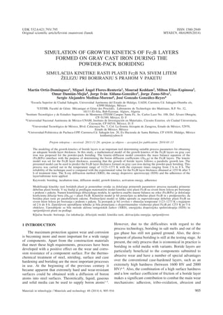
- 1. M. ORTIZ-DOMÍNGUEZ et al.: SIMULATION OF GROWTH KINETICS OF Fe2B LAYERS ... SIMULATION OF GROWTH KINETICS OF Fe2B LAYERS FORMED ON GRAY CAST IRON DURING THE POWDER-PACK BORIDING SIMULACIJA KINETIKE RASTI PLASTI Fe2B NA SIVEM LITEM @ELEZU PRI BORIRANJU S PRAHOM V PAKETU Martin Ortiz-Domínguez1, Miguel Ángel Flores-Rentería1, Mourad Keddam2, Milton Elias-Espinosa3, Omar Damián-Mejía4, Jorge Iván Aldana-González5, Jorge Zuno-Silva1, Sergio Alejandro Medina-Moreno6, José Gonzalo González-Reyes4 1Escuela Superior de Ciudad Sahagún, Universidad Autónoma del Estado de Hidalgo, UAEH, Carretera Cd. Sahagún-Otumba s/n, 43990 Hidalgo, México 2USTHB, Faculté de Génie Mécanique et Génie des Procédés, Laboratoire de Technologie des Matériaux, B.P. No. 32, 16111 El-Alia, Bab-Ezzouar, Algiers, Algeria 3Instituto Tecnológico y de Estudios Superiores de Monterrey-ITESM Campus Santa Fe, Av. Carlos Lazo No. 100, Del. Álvaro Obregón, CP. 01389, México, D. F. 4Universidad Nacional Autónoma de México-UNAM, Instituto de Investigación en Materiales, Circuito Exterior, s/n Ciudad Universitaria, Coyoacán, CP 04510, México, D. F. 5Universidad Tecnológica de México, Blvd. Calacoaya No. 7, Col. La Ermita Atizapán de Zaragoza, Estado de México, 52970, Estado de México, México 6Universidad Politécnica de Pachuca-UPP, Carretera-Cd. Sahagún km. 20, Ex Hacienda de Santa Bárbara, CP 43830, Hidalgo, México keddam@yahoo.fr Prejem rokopisa – received: 2013-11-29; sprejem za objavo – accepted for publication: 2014-01-13 The modeling of the growth kinetics of boride layers is an important tool determining suitable process parameters for obtaining an adequate boride-layer thickness. In this study, a mathematical model of the growth kinetics of the Fe2B layers on gray cast iron was proposed for the powder-pack boriding. The kinetic-diffusion model considers the mass balance equation of the (Fe2B/Fe) interface with the purpose of determining the boron diffusion coefficients (DFe2B) in the Fe2B layers. The kinetic model was set for the Fe2B layer thickness, assuming that the growth of boride layers follows a parabolic growth law. The presented model can be used to predict the Fe2B layer thickness formed on gray cast iron during the powder-pack boriding. This process was carried out in the temperature range of 1123–1273 K with the exposure times ranging from 2 h to 8 h. The reliability of the technique used is compared with the experimental value for the Fe2B layer thickness obtained at 1253 K after 5 h of treatment time. The X-ray diffraction method (XRD), the energy dispersive spectroscopy (EDS) and the adherence of the layer/substrate were applied. Keywords: boriding, incubation time, diffusion model, growth kinetics, activation energy, adherence Modeliranje kinetike rasti boridnih plasti je pomembno orodje za dolo~anje primernih parametrov procesa nastanka primerne debeline plasti borida. V tej {tudiji je predlagan matemati~ni model kinetike rasti plasti Fe2B na sivem litem `elezu pri boriranju s prahom v paketu. Namen kineti~nega difuzijskega modela, ki upo{teva ena~bo masne balance na stiku (Fe2B/Fe) je dolo~anje koeficienta difuzije bora (DFe2B) v plasti Fe2B. Kineti~ni model je bil postavljen za debelino plasti Fe2B in s predpostavko, da boridna plast raste po paraboli~nem zakonu. Predstavljeni model se lahko uporabi za napovedovanje debeline plasti Fe2B na sivem litem `elezu pri boriranju s prahom v paketu. Ta postopek je bil izvr{en v obmo~ju temperatur 1123–1273 K s trajanjem od 2 h do 8 h. Zanesljivost uporabljene tehnike je bila primerjana z eksperimentalno vrednostjo plasti Fe2B pri 1253 K po 5 h obdelave. Uporabljene so bile metode uklona rentgenskih `arkov (XRD), energijska disperzijska spektroskopija (EDS) in oprijemljivost plasti na podlagi. Klju~ne besede: boriranje, ~as inkubacije, difuzijski model, kinetika rasti, aktivacijska energija, oprijemljivost 1 INTRODUCTION The maximum protection against wear and corrosion is becoming more and more important for a wide range of components. Apart from the construction materials that meet these high requirements, processes have been developed with a positive effect on the wear and corro- sion resistance of a component surface. For the thermo- chemical treatment of steel, nitriding, surface and case hardening and boriding are the most important processes in use. At the beginning of the previous century it became apparent that extremely hard and wear-resistant surfaces could be obtained with a diffusion of boron atoms into steel surfaces. Theoretically, liquid, gaseous and solid media can be used to supply boron atoms1–3. However, due to the difficulties with regard to the process technology, boriding in salt melts and out of the gas phase has still not gained ground. Also, the deve- lopment of plasma boriding is still at the testing stage. At present, the only process that is economical in practice is boriding in solid media with variants. Boride layers are particularly beneficial to the components submitted to abrasive wear and have a number of special advantages over the conventional case-hardened layers, such as an extremely high hardness (between 1600 HV and 2000 HV)4–8. Also, the combination of a high surface hardness and a low surface coefficient of friction of a boride layer makes a significant contribution to combat the main wear mechanisms: adhesion, tribo-oxidation, abrasion and Materiali in tehnologije / Materials and technology 48 (2014) 6, 905–916 905 UDK 532.6:621.793/.795 ISSN 1580-2949 Original scientific article/Izvirni znanstveni ~lanek MTAEC9, 48(6)905(2014)
- 2. surface fatigue. This fact has enabled the mold makers to substitute easier-to-machine steels for the base metal and to still obtain the wear resistance and anti-galling properties superior to those of the original material. The hardness of a boride layer can be retained at higher temperatures. Boriding can considerably enhance the corrosion-erosion resistance of ferrous materials in non-oxidizing dilute acids and alkali media, and it is increasingly used due to this advantage in many industrial applications7. The term boriding means the enrichment of the surface of a workpiece with boron atoms with thermo- chemical treatment. Generally, the growth kinetics of solid phases is controlled with the diffusion of elements in theses phases1. The displacement speed of interfaces is analyzed in dependence of diffusion fluxes of elements to and from these interfaces. It is assumed that the bal- ance of diffusion fluxes of diffusion elements (pene- trating into an individual phase and leaving this phase) determines the growth (or reduction) of the layers of the phases and their thicknesses. If only one element is negligible and small with respect to the first element, the balance of diffusion fluxes is reduced to the arrival and the departure of the element at the phase interface9. By means of thermal energy, boron atoms are transferred into the lattice of the parent material, forming the res- pective borides. The boriding of steel alloys results in a formation of either a single-phase or a double-phase layer of boride with definite compositions. A single- phase boride layer consists of Fe2B (containing approxi- mately 60 × 103 mol m–3 of boron), while a double-phase layer consists of an outer phase of FeB (containing approximately 100 × 103 mol m–3 of boron) and an inner phase of Fe2B10. The FeB phase is brittle and forms a highly tensile-stressed surface. The Fe2B phase is pre- ferred because it is less brittle and forms a surface with a high compressive stress. The thickness of the boride layer formed depends on the temperature and the treat- ment time9–20. Although small amounts of FeB are present in most boride layers, they are not detrimental if not continuous. However, a continuous layer of FeB can lead to crack formation at the (FeB/Fe2B) interface. Fur- thermore, since the FeB and Fe2B phases exhibit sub- stantially different coefficients of thermal expansion (aFeB = 8.4·10–8 K–1, aFe2B = 2.9·10–8 K–1) in the tempe- rature range of 473–873 K, crack formations are often observed at the (FeB/Fe2B) interface of a double-phase layer. These cracks can lead to a separation of spalling of a double-phase layer when a mechanical strain is applied or when the component is submitted to a thermal and/or a mechanical shock2. Fortunately, continuous layers of FeB can be minimized by diffusion annealing after bo- ride formation9,21. Also, the boriding powders that minimize the formation of FeB have been developed and are available. The preferred morphology is a sawtooth of the serrated-boride-layer structure, most easily obtained with carbon or low-alloy steels3,10,17,22,23. The micro- hardness of a boride layer also depend strongly on the composition and structure of the boride layer and of the base material. In practical applications of boriding, the selection of process parameters is important in order to attain the desired thickness of a boride layer and a hardness gradient. The thickness of a boride layer that affects the mechanical and chemical behavior of a mate- rial depends on the boriding temperature, the boriding time, the active-boron quantity at a sample surface and the chemical composition of the material10,12,23. There- fore, estimating the kinetics parameters of developing boride layers during the boriding process is crucial. The growth kinetics of iron boride layers has received a particular interest in the field of boriding treatment in order to automate and optimize the process. For this reason, different mathematical models have been proposed to determine the boron diffusion coefficients of borides5,8,10,16,18,19,22–25. Most of these models consider the thermodynamic equilibrium at the interface during the growth and a linear boron-concentration profile for the boride layer. Nevertheless, mathematical models are sen- sitive to the experimentally obtained boride-layer thick- ness, which is the main reason for a lack of data about boron diffusion coefficients for boride layers. Likewise, the dependence of the temperature and boron diffusion coefficient can be deducted with the Arrhenius equation, which makes it possible to calculate the boron diffusion activation energy (QFe2B). In this study the boriding of the surface of gray cast iron hardened during the powder- pack process is analyzed on the basis of the growth kinetics of the Fe2B layers formed on the surface of gray cast iron due to powder-pack boriding. The parabolic growth constants of Fe2B were determined and the boron diffusion coefficient for the boride layer was estimated using a diffusion model based on the conditions of the boriding process and the Fe-B system. Moreover, X-ray diffraction (XRD), scanning electron microscopy (SEM) and energy dispersive X-ray spectroscopy (EDS) were conducted on the borided material to characterize the presence of the Fe2B layer and the distribution of heavy elements on the surface of gray cast iron. In addition, the Daimler-Benz Rockwell-C indentation tests were also applied (prescribed by the VDI 3198 norm) exhibiting distinct properties of the coated compound, i.e., inter- facial adhesion, coating brittleness and cohesion. 2 DIFFUSION MODEL 2.1 Mass-balance equation The model considers a system in which a solute is added to the surface of a two-phase alloy with a compo- sition of C0 » 0 mol m–3. As boron is added to the sur- face, it is used completely to convert the Fe phase to Fe2B. There is no boron flux out of the surface layer of Fe2B into the two-phase alloy. The boron concentration along the depth of the sample surface is depicted in Figure 1. The first step corresponds to a normal diffusion process before the formation of Fe2B layers. For this period, labeled as time t0 Fe B2 in Figure 1, the boron M. ORTIZ-DOMÍNGUEZ et al.: SIMULATION OF GROWTH KINETICS OF Fe2B LAYERS ... 906 Materiali in tehnologije / Materials and technology 48 (2014) 6, 905–916
- 3. concentration profile in austenite corresponding to f(x) and marked with a dashed line, is displayed in Figure 1 (where f(x) denotes the initial concentration profile when the layer formation begins). In the model, this is equivalent to the "supersaturated" austenite. In this period, the formation of compact layers begins to take place, as shown in Figure 1, where C up Fe B2 is the upper limit of the boron amount in Fe2B (= 60×103 mol m–3), C low Fe B2 is the lower limit of the boron amount in Fe2B (= 59.8×10³ mol m–3) and point x(t) = v width of the Fe2B layer9,10. Note that in this case, the position of the discontinuity does not correspond to the thermodyna- mic-phase equilibrium associated with the limits of solubility of each phase in the Fe-B phase diagram. The boron concentration of the Fe2B phase in equilibrium with austenite has its value determined on the basis of the intersection with f(x) "supersaturated" austenite. The term C ads B is the effective boron concentration or the adsorbed boron concentration in the boride layer during the boriding process13 . On Figure 1, a C C1 = −up Fe B low Fe B2 2 defines the homogeneity range of the Fe2B layer, a C C2 0= −low Fe B2 is the miscibility gap and C0 is the terminal solubility of the interstitial solute. The boron solubility in the austenite phase is very low and can be neglected by setting C0 » 0 mol m–3.26,27 Certain assumptions are considered in the establishment of the diffusion model: a) The diffusion model was not based on the boron concentration profile CFe2B [x(t)] of the Fe2B layer (Figure 1). b) The growth kinetics is controlled by the boron diffusion in the Fe2B layer. c) Fe2B nucleates after a period of incubation. d) The boride layer grows because of the boron diffusion perpendicular to the specimen surface. e) Boron concentrations remain constant in the boride layer during the treatment. f) The influence of the alloying elements on the growth kinetics of the layer is not taken into account. g) The boride layer is thin compared to the sample thickness. h) A uniform temperature throughout the sample is assumed. i) A planar morphology is assumed for the phase inter- face. With these assumptions, the initial and boundary con- ditions can be written as (Figure 1): Initial condition: t = 0, x > 0, with: CFe2B [x(t)] = C0 » 0 (1) Boundary conditions: [ ]C x t t v CFe B Fe B up Fe B 2 2 2 ( )= = =0 0 (2) (The upper boron concentration is kept constant), for C ads B > 60×103 mol m–3 : [ ]C x t t v CFe B low Fe B 2 2 ( )= = = (3) (The boron concentration at the interface is kept constant), for C ads B < 59.8×10³ mol m–3 where tv (= t – t0 Fe B2 ) is the effective growth time of the Fe2B layer, t is the treatment time, t0 Fe B2 is the boride incubation time and v0 the initial Fe2B layer related with the initial period t0 Fe B2 of the interaction of elementary substances (boron atoms and substrate) due to the presence of the Fe2B layer. In addition, v0 is a thin layer with a thickness of » 5 nm formed during the nucle- ation stage.28 However, the value of v0 » 0 is small in comparison with the measured thickness of the Fe2B layer (v) and it can, therefore, hardly have a noticeable effect on the shape of the layer thickness-time depen- dences observed in practice. Given the aforementioned conditions, it is taken into account that the boride-layer thickness v is governed by the parabolic growth law, v D t= 2 1 2 e Fe B 1/2 2 / = +2 0 1 2 eD t tFe B 1/2 v Fe B 2 2 ( ) / , where e is the normalized growth parameter for the (Fe2B/substrate) interface29, and DFe2B denotes the diffusion coefficient of boron in the Fe2B phase. In an infinitesimally small time interval dt the growth of Fe2B occurs due to a simultaneous consumption of the substrate at the (Fe2B /substrate) interface boundary. Considering that dv (Figure 1) is an extension of the Fe2B layer in a time interval (dt) boron atoms should be conserved at the (Fe2B/substrate) interface. Hence, applying the rule of mass conservation at the (Fe2B/substrate) interface,30,31 M. ORTIZ-DOMÍNGUEZ et al.: SIMULATION OF GROWTH KINETICS OF Fe2B LAYERS ... Materiali in tehnologije / Materials and technology 48 (2014) 6, 905–916 907 Figure 1: Boron concentration profile for the Fe2B layer, C up Fe B2 and C low Fe B2 values obtained from the Fe-B phase diagram for a range of temperature Slika 1: Profil koncentracije bora v plasti Fe2B; vrednosti C up Fe B2 in C low Fe B2 , dobljene iz faznega diagram Fe-B za obmo~je temperatur
- 4. which is schematically represented in Figure 2, is defined as: C C C A v J x v A up Fe B low Fe B Fe B 2 2 2 d + −⎛ ⎝ ⎜ ⎜ ⎞ ⎠ ⎟ ⎟ ⋅ = = = ⋅ 2 2 0 ( ) ( )( d d dFet J x v v A t) ( )( )− = + ⋅ (4) where A (=1·1) is defined as the unit area. Assuming that the diffusion of the metal component is negli- gible16,24 nearly all the growth of the Fe2B layer can be explained on the basis of the diffusivity of boron atoms. On the other hand, the input and output fluxes of boron atoms at the (Fe2B/substrate) interface boundary in time interval dt are defined as: J x v D dC x t dx x vFe B Fe B Fe B2 2 2 ( ) ( ) /= =− ={ [ ] } , and J x v v D dC x t dx x v vFe Fe Fe dd( ) ( ) /= + =− = +{ [ ] } respectively. Considering that the boron solubility in the g phase has a small value (» 0 mol m–3) in comparison with the lower limit (C low Fe B2 ) of the boron amount in Fe2B (= 59.8×10³ mol m–3), the output flux can be neglected (JFe (x = v + dv) = –{DFedCFe[x(t)]/dx}x=v+dv » 0). Given these conditions, Equation 4 corresponds to the mass- balance equation and can be rewritten as: C C C x t t D x t v up Fe B low Fe B Fe B 2 2 2 d d + −⎛ ⎝ ⎜ ⎜ ⎞ ⎠ ⎟ ⎟ = =− = 2 2 0 ( ) ( ) d d Fe B2 C x t x t x t v [ ]( ) ( ) ( )= (5) Using the chain rule on the right term of Equation 5 results in: C C C x t t D x t v up Fe B low Fe B Fe B 2 2 2 d d + −⎛ ⎝ ⎜ ⎜ ⎞ ⎠ ⎟ ⎟ = =− = 2 2 0 ( ) ( ) d d d d Fe B2 C x t t t x t x t v [ ]( ) ( ) ( ) ⎛ ⎝ ⎜ ⎞ ⎠ ⎟ ⎛ ⎝ ⎜ ⎞ ⎠ ⎟ = (6) Hence, rearranging Equation 6 yields: C C C x t t x t v up Fe B low Fe B2 2 d d d + −⎛ ⎝ ⎜ ⎜ ⎞ ⎠ ⎟ ⎟ ⎛ ⎝ ⎜ ⎞ ⎠ ⎟ = 2 2 0 2 ( ) ( ) t D C x t x t v = =− = Fe B Fe B2 2 d [ ]( ) ( ) (7) Incorporating the parabolic growth law (v x t= =( ) 2 1 2 eD tFe B 1/2 2 / ) on the left term of Equation 7, Equation 8 is obtained: C C C t t C x t x up Fe B low Fe B 2 Fe B 2 2 2 d d + −⎛ ⎝ ⎜ ⎜ ⎞ ⎠ ⎟ ⎟ = =− 2 2 0 e [ ]( ) ( )t v= (8) A schematic representation of the square of the layer thickness against the linear time is depicted in Figure 3. Now, we integrate both sides of Equation 8 between the limits of t0 Fe B2 to t and C up Fe B2 to C low Fe B2 , respectively: C C C t t C t t up Fe B low Fe B 2 Fe 2 2 Fe 2 B d d + −⎛ ⎝ ⎜ ⎜ ⎞ ⎠ ⎟ ⎟ = =− ∫ 2 2 0 0 e 2 up Fe 2 B low Fe 2 B B C C x t v x t∫ = [ ]( ) ( ) (9) The following solution is derived: e2 up Fe B low Fe B up Fe B low Fe B 2 2 2 2 = − + − ⎛ ⎝ ⎜ ⎜ ⎞ ⎠ ⎟ ⎟ 2 2 0 C C C C C ln t t0 Fe B2 ⎛ ⎝ ⎜ ⎞ ⎠ ⎟ (10) M. ORTIZ-DOMÍNGUEZ et al.: SIMULATION OF GROWTH KINETICS OF Fe2B LAYERS ... 908 Materiali in tehnologije / Materials and technology 48 (2014) 6, 905–916 Figure 3: Schematic representation of the square of the Fe2B layer thickness against the treatment time Slika 3: Shematski prikaz odvisnosti korena debeline plasti Fe2B od ~asa obdelave Figure 2: Schematic representation of the mass-balance equation at the (Fe2B/substrate) interface Slika 2: Shematski prikaz ena~be ravnote`ja mas na stiku Fe2B-pod- laga
- 5. where e is known as the normalized growth parameter for the (Fe2B/substrate) interface, having no physical dimensions. It is assumed that expressions C up Fe B2 , C low Fe B2 , and C0 do not depend significantly on the temperature (in the temperature range applied).10 3 EXPERIMENTAL PROCEDURE 3.1 Boriding process Gray cast iron, class 30, complying with the ASTM A-48 standard was employed. Cubic samples with the dimensions of 10 mm × 10 mm × 10 mm of the alloy with the chemical composition of 3.44–3.45 % C, 1.7–1.77 % Si, 0.5–0.6 % Mn, 0.2 % Cr, and 0.45–0.5 % Cu were prepared. Prior to boriding the specimens were polished, ultrasonically cleaned in an alcohol solution in deionized water for 15 min at room temperature, dried and stored under clean-room conditions. The resulting microstructure of the gray cast iron after the solution treatment is presented in Figure 4a. It consists of gra- phite flakes (Figure 4b) and a pearlitic matrix with the mean hardness of approximately 316 HV0.05. The samples were embedded in a closed cylindrical case (AISI 304L) as shown in Figure 5, containing a Durborid fresh-powder boriding medium with the ave- rage size of 30 μm (Figure 6), consisting of an active boron source (B4C), an inert filler (SiC) and an activator (KBF4). The boron potential was controlled with the powder quantity placed over and around the material surface. The powder-pack boriding was performed in a con- ventional furnace under a pure argon atmosphere. It is important to note that the oxygen-bearing compounds adversely affect the boriding process1. The temperatures of (1123, 1173, 1223, and 1273) K for (2, 4, 6 and 8) h were selected. The boriding temperatures were selected in accordance with the position of the solidus line in the Fe-B phase diagram. Once the treatment was completed, the container was removed from the furnace and slowly M. ORTIZ-DOMÍNGUEZ et al.: SIMULATION OF GROWTH KINETICS OF Fe2B LAYERS ... Materiali in tehnologije / Materials and technology 48 (2014) 6, 905–916 909 Figure 6: SEM image of boriding powder (B4C + KBF4 + SiC) Slika 6: SEM-posnetek prahu za boriranje (B4C + KBF4 + SiC) Figure 4: a) Microstructure of gray cast iron after solution treatment, b) SEM micrograph of a graphite flake Slika 4: a) Mikrostruktura sivega litega `eleza po raztopnem `arjenju, b) SEM-posnetek grafitnega listi~a Figure 5: Schematic view of the stainless steel AISI 304L container for the powder-pack boriding treatment: 1 – lid; 2 – powder boriding medium (B4C + KBF4 + SiC); 3 – sample; 4 – container Slika 5: Shematski prikaz posode iz nerjavnega jekla AISI 304L za boriranje s prahom v paketu; 1 – pokrov; 2 – pra{nati medij za bori- ranje (B4C + KBF4 + SiC); 3 – vzorec; 4 – posoda
- 6. cooled to room temperature. After the preliminary expe- riments it was estimated that the boriding started appro- ximately » 31 min after transferring a specimen to the furnace; after that, the so-called boride incubation time set in. 3.2 Characterization of boride layers The boride samples were cross-sectioned for metal- lographic examinations using a LECO VC-50 precision- cutting machine and the depths of the surface layers were observed in a clear field with light microscopy using a GX51 Olympus instrument. Figure 7 depicts the growth of the Fe2B layers at the surface of the borided gray cast iron for a particular boriding temperature (1223 K). The images were then analyzed with the MSQ PLUS soft- ware. The thickness measurement program is designed to measure the thickness of layers. The measurement of the layer thickness is exceedingly crucial for the study of the boride-layer growth kinetics. Automatic measurements can be performed by constructing a series of parallel section lines combined with a thresholded image of the layer to be measured. The lengths of those portions of the section lines that overlay the selected layer are measured. In order to minimize the roughness effect on the interface growth, the layer thickness was defined as the average value of the long boride teeth2,9,14,18,23,25. Fifty measurements were collected in different sections of the ASTM A-48 borided samples to estimate the thickness of the Fe2B layers. All the thickness measurements were collected from a fixed reference on the surface of a borided specimen, as shown in Figure 8. The presence of the iron boride formed at the surface of the sample was verified with X-ray diffraction (XRD), using the equipment (Equinox 2000) with Co Ka radiat- ion at l = 0.179 nm. The distribution of the alloying ele- ments in a boride layer on gray cast iron was determined with electron dispersive spectroscopy (EDS) (JEOL JSM 6300 LV) from the surface. A Daimler-Benz Rocwell-C adhesion test was employed to assess the adhesion of boride layers. The Rockwell-C indentation test is pre- scribed by the VDI 3198 norm as a destructive quality test of coated compounds.32–34 The principle of this method is found in the reference work.34 A load of 1471 N was applied to cause coating damage adjacent to the boundary of the indentation. Three indentations were conducted for each specimen and scanning electron microscopy (SEM) was employed to evaluate the results. M. ORTIZ-DOMÍNGUEZ et al.: SIMULATION OF GROWTH KINETICS OF Fe2B LAYERS ... 910 Materiali in tehnologije / Materials and technology 48 (2014) 6, 905–916 Figure 8: Schematic diagram illustrating the procedure of estimating the boride-layer thickness in gray cast iron Slika 8: Shematski prikaz postopka dolo~anja debeline plasti borida na sivem litem `elezu Figure 7: Light micrographs of the Fe2B layers formed at the surface of the borided ASTM A-48 alloy at 1223 K with the exposure times of: a) 2 h, b) 4 h, c) 6 h and d) 8 h Slika 7: Svetlobni mikroskopski posnetki plasti Fe2B, nastale na povr- {ini borirane zlitine ASTM A-48 pri 1223 K in trajanju: a) 2 h, b) 4 h, c) 6 h in d) 8 h
- 7. 4 RESULTS AND DISCUSSIONS 4.1 Formation mechanism of the borided layer In the powder-pack boriding, the in-diffusion of atomic boron leads to the formation of borided case structures displaying a boron amount gradient. It is important to recall the overall chemical reaction that takes place during the powder-pack boriding process, i.e.: B4C + 4KBF4 + 3SiC + 2O2 ® ® 8B (adsorption) + 4KF + 3SiF4 + 4CO (11) The presence of oxygen promotes oxidation of active boron and Equation (11) will be changed to Equation (12): B4C + 4KBF4 + 3SiC + 2O2 ® ® 6B (adsorption) + 4KF + 3SiF4 + 4CO + B2O2 (12) The powder-pack boriding is best done in an inert gas of Ar or N2. Argon (welding-grade argon is sufficient), unlike nitrogen, has a higher specific weight than air. Therefore, it is more able to drive out oxygen and carbon dioxide from the retort and, for this reason, it is more suitable for use as the inert gas than nitrogen or forming gas. All carbon-dioxide- and carbon-monoxide-bearing gases as well as damp inert gas are unsuitable. The sur- face of a sample is exposed to the gaseous atmosphere of the atomic boron released from the chemical reaction (Equations 11 and 12) into the substrate, and all the chemical connections (metallic) of the constituent atoms (Fe) are satisfied. However, by definition, the surface represents a discontinuity of those connections. For these incomplete connections, it is strongly favorable to react with the atomic boron that is available, and for that reason it takes place in a spontaneous form. The exact nature of the connection depends on the specimen specificity, but the adsorbed material is generally classified as a chemisorbed material. It can be defined as the concentration (C ads B ) of the solute (boron atoms) on the surface of a sample (Figure 1). If the boron concen- tration is in the composition range of C low Fe B2 < C up Fe B2 < C ads B , by reacting with active boron atoms B from Equations (11) and (12), the Fe phase can transform into the Fe2B phase (B(adsorption) + 2Fe ® Fe2B). The growth dynamics of the boride coating will be described, distinguishing between the three subsequent stages. During the first stage, it corresponds to the normal diffusion process, which takes place before the formation of the Fe2B layer. To this period, labeled as time t0 Fe B2 in Figure 1, the initial Fe2B layer (v0) and the concentration profile (f(x)) are associated. The nucleation of the iron boride at the gas-solid interface is the net result of the competition between the supply of boron from the gas phase and the removal of boron due to diffusion into the substrate. During the second stage, significant amounts of Fe2B crystals form and grow inside, towards the metal bulk. During the third stage, all Fe2B crystals form and grow inside assuming the preferred crystallographic orientation. Because the growth of the saw-toothed boride layer is a controlled diffusion process with a highly anisotropic nature, higher temperatures and/or longer times stimulate the Fe2B crystals to make contact with the adjacent crystals and force them to retain the acicular shape35. A. J. Ninham and I. M. Hutchings36 suggested that the columnar nature of the coating inter- face is caused by a dendrite "side-arm" growth similar to the growth that occurs during the solidification of many metallic systems. In borided low-carbon steels, the boride may "break through" the band of impurities in some places, which allows a rapid local boride growth and results in the characteristic saw-toothed interface. A different mechanism was also proposed, in which local high-stress fields and lattice distortions near the tips of the first acicular nuclei of the reaction products are assumed to be responsible for the columnar growth of borides37. 4.2 Characterization of boride coatings A SEM micrograph of the cross-section of the gray cast iron, borided at a temperature of 1123 K for 6 h, is shown in Figure 9a. The EDS analysis obtained with SEM is depicted in Figure 9b. The results show that chromium dissolves in Fe2B due to the atomic radius of Cr (= 0.166 nm) which is only a little larger than that of M. ORTIZ-DOMÍNGUEZ et al.: SIMULATION OF GROWTH KINETICS OF Fe2B LAYERS ... Materiali in tehnologije / Materials and technology 48 (2014) 6, 905–916 911 Figure 9: a) Micrograph image of the microstructure of the gray- cast-iron boride layer obtained at 1123 K after an exposure time of 6 h, b) EDS spectrum of a borided sample Slika 9: a) Mikrostruktura boridne plasti na sivem litem `elezu, na- stale pri 1123 K po 6 h, b) EDS-spekter boriranega vzorca
- 8. Fe (= 0.155 nm). It can be expected that Cr replaces Fe in the lattice of boride. Manganese appears to have a lower solubility. Thus, a deficiency of manganese results in a negative effect on the boride layer in terms of both thickness and morpho- logy. Carbon and silicon do not dissolve significantly across the phase and they do not diffuse through the boride layer, being displaced to the diffusion zone and forming, together with boron, solid solutions like silico- borides (FeSi0.4B0.6 and Fe5SiB2) and boron-cementite (Fe3B0.67C0.33)10,38. 4.3 X-ray diffraction analysis The presence of Fe2B layers was verified with XRD patterns, as shown in Figure 10, in the boundary zones of the borided layers, where it is normally possible to find mixed crystals of different phases. The crystals of the Fe2B type orientate themselves with the z-axis per- pendicular to the surface. Consequently, the peaks of the Fe2B type phases corresponding to crystallographic planes, with a deviation from zero of the l index, show increased intensities in the X-ray diffraction spectra39. The growth of boride layers is a controlled diffusion process with a highly anisotropic nature. In the Fe2B phase, the crystallographic direction [001] is the easiest path for the boron diffusion in the body-centered tetra- gonal lattice of the Fe2B phase, due to the tendency of boride crystals to grow along the direction of minimum resistance, perpendicular to the external surface. As the metal surface is covered, an increasing number of Fe2B crystals come in contact with the adjacent crystals, being forced to grow inside the metal and retaining an acicular shape35. The studies on borided cast irons determined the presence of FeB/Fe2B layers at a sample surface40–43. Here, the boron source that provides the boron potential, surrounding the material surface, seems to have influenced the formation of one phase, and only reaches the concentration limits at the surface to create the Fe2B phase. It is known that the media with a low or interme- diate boron potential (as compared to the more powerful ones) allow the formation of single Fe2B layers12,44,45. In industrial applications, it is desirable to have only the Fe2B phase instead of FeB/Fe2B layers due to significant differences between the expansion coefficients for both phases, which can accelerate the formation of cracks induced by internal stresses. 4.4 Rockwell-C adhesion For a destructive test of the adhesion of the examined layers a Daimler-Benz Rockwell-C indenter hardness M. ORTIZ-DOMÍNGUEZ et al.: SIMULATION OF GROWTH KINETICS OF Fe2B LAYERS ... 912 Materiali in tehnologije / Materials and technology 48 (2014) 6, 905–916 Figure 11: Principle of the VDI 3198 indentation test32 Slika 11: Princip VDI 3198-preizkusa z vtiskovanjem32 Figure 10: XRD patterns obtained for the surface of the borided ASTM A-48 gray cast iron at 1273 K after 8 h of treatment Slika 10: XRD-posnetek povr{ine boriranega sivega litega `eleza ASTM A-48 pri 1273 K po 8 h obdelave Figure 12: SEM micrographs: a) adjacent to the boundary of the indentation and b) center of the indentation of the VDI adhesion test on gray cast iron Slika 12: SEM-posnetka VDI-preizkusa adhezije na sivem litem `ele- zu: a) v bli`ini meje vtiska in b) v sredini vtiska
- 9. tester was employed, prescribed by the VDI 3198 norm32. The principle of this method is presented in Figure 11. A conical diamond indenter penetrates into the surface of the investigated layer, inducing a massive plastic deformation of the substrate and fracture of the boride layer. The damage of the boride layer was com- pared with the adhesion-strength quality maps HF1-HF6 (Figure 11). In general, the adhesion strengths HF1 to HF4 define a sufficient adhesion, whereas HF5 and HF6 represent an insufficient adhesion (HF is the German abbreviation for adhesion strength)32. Scanning electron microscopy (SEM) images of the indentation craters for the samples borided at 1273 K for 4 h are given in Figure 12. The indentation craters ob- tained on the surface of the borided gray cast iron revealed radial cracks at the perimeters of indentation craters. However, a small quantity of spots with delami- nation flakes was visible and the adhesion-strength quality of this boride layer corresponded to the HF3 standard. 4.5 Growth kinetics of boride layers The thickness growth of boride layers as a function of the exposure time is depicted in Figure 13. The slopes of the straight lines in Figure 13 represent the growth constants (= 4e2DFe2B) of the parabolic growth law (v2 = 4e2DFe2Bt), where the intercept on the abscissa is taken as the boride incubation time on the graph. The results summarized in Table 1 reflect the diffu- sion-controlled growth of the boride layers. By combin- ing the results (square of normalized growth parameter (e2) and growth constants (4e2DFe2B) presented in Table 1, the boron diffusion coefficient for the Fe2B layers (DFe2B) was estimated for each boriding temperature. Table 1: Square of normalized growth parameter and growth constants as a function of the boriding temperature Tabela 1: Kvadrat parametra normalizirane rasti in konstante rasti kot funkcija temperature boriranja Temperature (K) Type of layer e2 (Dimen- sionless) 4e2DFe2B/ (ìm2 s–1) 1123 Fe2B 1.689625×10⁻³ 1.66×10⁻¹ 1173 4.52×10⁻¹ 1223 9.81×10⁻¹ 1273 16.8×10⁻¹ The activation energy (QFe2B) and the pre-exponential factor (D0) calculated from the slopes and intercepts of the straight line, shown in coordinate system ln DFe2B as a function of the reciprocal boriding temperature is pre- sented in Figure 14. The linear relationship is assumed (with the correlation factor of 0.9908): DFe2B = 9.8×10⁻³ exp(–184.2 kJ mol–1 / RT) (13) M. ORTIZ-DOMÍNGUEZ et al.: SIMULATION OF GROWTH KINETICS OF Fe2B LAYERS ... Materiali in tehnologije / Materials and technology 48 (2014) 6, 905–916 913 Figure 14: Boron diffusion coefficient (DFe2B) as a function of the boriding temperature Slika 14: Difuzijski koeficient bora (DFe2B) v odvisnosti od tempe- rature boriranja Figure 13: Square of the Fe2B layers thickness (v2) versus boriding time (t) at different temperatures Slika 13: Odvisnost kvadrata debeline plasti Fe2B (v2 ) od ~asa bori- ranja (t) pri razli~nih temperaturah Figure 15: Light micrograph of the boride layer formed on gray cast iron during the powder-pack boriding at 1253 K after an exposure time of 5 h Slika 15: Svetlobni posnetek mikrostrukture boridne plasti na sivem litem `elezu pri boriranju s prahom v paketu pri 1253 K in trajanju 5 h
- 10. where R = 8.3144621 J mol–1 K–1 and T is the absolute temperature (K). According to Equation 13, the pre- exponential factors and the activation-energy values are affected by the contact surface between the boriding medium and the substrate, as well as the chemical com- position of the material12,17. The growth kinetics of boride layers obtained with the diffusion model was verified by estimating the Fe2B layer thickness as a function of the temperature and exposure time. Figure 15 shows a light image of the boride layer formed at 1253 K after 5 h of treatment. With Equation 14, the boride-layer thicknesses are described as follows: v D t D t C C t t = = − 2 8 1 2 e Fe B 1/2 Fe B up Fe B low Fe B 0 F2 2 2 2 / ( ) ln( / e B up Fe B low Fe B2 2 2 )( )C C C+ −2 0 (14) As depicted in Table 2, the results obtained from Equation 14 exhibit a good agreement between the experimental data and the theoretical results. Table 2: Estimated value of the gray-cast-iron boride-layer thickness (v) obtained at a boriding temperature of 1253 K with an exposure time of 5 h Tabela 2: Izmerjene debeline (v) plasti borida na sivem litem `elezu, nastale pri 1253 K in trajanju boriranja 5 h Temperature (K) Type of layer Boride-layer thickness (μm) estimated with Eq. 14 Experimental boride-layer thickness (μm) 1253 Fe2B 148.34 154.34±16.52 The Fe2B layer thicknesses for the set of experimen- tal parameters of the borided gray cast iron are presented with contour plots as functions of the temperature and exposure time as shown in Figure 16. Hence, Equation 14 can be used to estimate the optimum boride-layer thicknesses for the borided gray cast iron. It is a standard practice to match the case depth with the intended indu- strial application and the base material. As a rule, thin layers (e.g., 15–20 μm) are used to protect against adhesive wear (associated with chipless shaping and metal-stamping dies and tools), whereas thick layers are recommended for combating abrasive wear (extrusion tooling for plastics with abrasive fillers and pressing tools for the ceramic industry). In the case of low-carbon steels and low-alloy steels, the optimum boride-layer thickness ranges from 50 μm to 250 μm, and for high-alloy steels, the optimum boride-layer thickness ranges from 25 μm to 76 μm. In addition, this model can be extended to predict the growth kinetics of FeB/Fe2B boride coatings on the surfaces of different ferrous alloys. 5 CONCLUSIONS The growth kinetics of a boride layer (Fe2B) on gray cast iron was evaluated with a mathematical model. The boride incubation time was taken into account for the powder-pack boriding and the main assumptions were adopted on the basis of reference10. The dependence between the boron diffusion coefficients and the boriding temperature was expressed with the Arrhenius equation for the temperature range of 1123–1273 K. An empirical equation was derived to predict the thickness of the boride layer for the temperatures between 1123 K and 1273 K with the boriding times between 2 h and 8 h. The validity of the diffusion model was tested by comparing the thickness of the experimental boride layer obtained with boriding 5 h with that deduced using the model (see Equation 14). On the other hand, the adhesion-strength quality of the boride layer formed on the surface of gray cast iron is estimated as HF3 after 4 h of boriding at 1273 K. The large differences or mismatches in the coefficients of the thermal expansion of Fe2B (aFe2B = 2.9×10⁻⁸ K–1) and Fe (aFe = 0.11×10⁻⁸ K–1) may have also played some roles in the large-scale delamination and flaking off the top Fe2B layer. The contour diagram, which can be used for future applications of borided gray cast iron, was developed not only to estimate the thickness of a boride layer with the used process para- meters but also to predict the process parameters on the basis of the thicknesses of boride layers. Acknowledgements The work described in this paper was supported by a grant of CONACyTand PROMEP México. Also, the authors want to thank Ing. Martín Ortiz Granillo, who is in charge as Director of the Escuela Superior de Ciudad Sahagún which belongs to the Universidad Autónoma del Estado de Hidalgo, México and Dr. Alejandro Domínguez, who is Coordinador del Programa para Apoyo a la Publicación de Investigaciones, Dirección de M. ORTIZ-DOMÍNGUEZ et al.: SIMULATION OF GROWTH KINETICS OF Fe2B LAYERS ... 914 Materiali in tehnologije / Materials and technology 48 (2014) 6, 905–916 Figure 16: Contour diagram for the estimation of process parameters and layer thickness Slika 16: Diagram obrisov debeline plasti za dolo~anje parametrov procesa
- 11. Desarrollo Curricular y NuevosProductos and Vicerrec- toríaAcadémica UNITEC for all the facilities to accomplish this research work. Nomenclature aFeB – thermal expansion coefficient of the FeB layer (K–1) aFe2B – thermal expansion coefficient of the Fe2B layer (K–1) v – boride layer thickness (m) kFe2B – rate constant in the Fe2B phase (m s–1/2) tv – effective growth time of the Fe2B layer (s) t – treatment time (s) t0 Fe B2 – boride incubation time (s) QFe2B –activation energy of the system (J mol –1 ) C up Fe B2 – upper limit of boron amount in Fe2B (60 × 103 mol m–3) C low Fe B2 – lower limit of boron amount in Fe2B (59.8 × 10³ mol m–3) C ads B – adsorbed boron concentration in the boride layer (mol m–3 ) a1 = C up Fe B2 –C low Fe B2 – homogeneity range of the Fe2B layer (mol m–3) a2 = C low Fe B2 – C0 – miscibility gap (mol m–3) C0 – terminal solubility of the interstitial solute (»0 mol m–3) CFe2B [x(t)] – boron concentration profile for the Fe2B layer (mol m–3) v0 – initial Fe2B layer (m) e – normalized growth parameter for the (Fe2B/substrate) interface (it has no physical dimensions) DFe2B – diffusion coefficient of boron in the Fe2B phase (m2 s–1 ) Ji[x(t)], (with i = Fe2B and Fe) – boron atom fluxes in the (Fe2B/substrate) interface (mol m–2 s–1) 6 REFERENCES 1 G. Wahl, Boronizing, Durferrit-Technical Information, Reprint from VDI-Z117, Germany 1975, 785–789 2 A. Graf von Matuschka, Boronizing, 1st ed., Carl Hanser Verlag, Munich 1980 3 J. R. Davis, Surface Hardening of Steels, Understanding the Basics, ASM International, USA 2002, 213–223 4 S. C. Singhal, Thin Solid Films, 45 (1977), 321–329 5 K. Genel, I. Ozbek, C. Bindal, Materials Science and Engineering, A347 (2003), 311–314 6 U. Yapar, C. F. Arýsoy, G. Basman, S. A. Yesilcubuk, M. K. Sesen, Key Engineering Materials, 264–268 (2004), 633–636 7 W. Fichtl, Rev. Int. Hautes Temper, 17 (1980), 33–43 8 I. Campos-Silva, M. Ortiz-Domínguez, N. López-Perrusquia, A. Me- neses-Amador, R. Escobar-Galindo, J. Martínez-Trinidad, Applied Surface Science, 256 (2010), 2372–2379 9 M. Kulka, N. Makuch, A. Pertek, L. Maldzinski, Journal of Solid State Chemistry, 199 (2013), 196–203 10 C. M. Brakman, A. W. J. Gommers, E. J. Mittemeijer, J. Mater. Res., 4 (1989), 1354–1370 11 S. Sen, U. Sen, C. Bindal, Vacuum, 77 (2005), 195–202 12 I. Campos, O. Bautista, G. Ramírez, M. Islas, J. De La Parra, L. Zúñiga, Applied Surface Science, 243 (2005), 431–438 13 L. G. Yu, X. J. Chen, K. A. Khor, G. Sundararajan, Acta Materialia, 53 (2005), 2361–2368 14 I. Campos, R. Torres, O. Bautista, G. Ramírez, L. Zuñiga, Applied Surface Science, 252 (2006), 2396–2403 15 O. Ozdemir, M. Usta, C. Bindal, A. H. Ucisik, Vacuum, 80 (2006), 1391–1395 16 X. J. Chen, L. G. Yu, K. A. Khor, G. Sundararajan, Surface and Coatings Technology, 202 (2008), 2830–2836 17 I. Campos-Silva, M. Ortiz-Dominguez, H. Cimenoglu, R. Escobar- Galindo, M. Keddam, M. Elias-Espinosa, N. López-Perrusquia, Surface Engineering, 27 (2011), 189–195 18 I. Campos-Silva, M. Ortiz-Domínguez, O. Bravo-Bárcenas, M. A. Doñu-Ruiz, D. Bravo-Bárcenas, C. Tapia-Quintero, M. Y. Jiménez- Reyes, Surface and Coatings Technology, 205 (2010), 403–412 19 M. Keddam, M. Ortiz-Domínguez, I. Campos-Silva, J. Martínez- Trinidad, Applied Surface Science, 256 (2010), 3128–3132 20 I. Gunes, Bulletin of Materials Science, 38 (2013), 527–541 21 I. Campos-Silva, M. Flores-Jiménez, G. Rodríguez-Castro, E. Her- nández-Sánchez, J. Martínez Trinidad, R. Tadeo-Rosas, Surface and Coatings Technology, 237 (2013), 429–439 22 I. Campos-Silva, M. Ortiz-Domínguez, C. Villa Velazquez, R. Esco- bar, N. López, Defect and Diffusion Forum, 272 (2007), 79–86 23 M. Ortiz Domínguez, Contribución de la Modelación Matemática en el Tratamiento Termoquímico de Borurización, PhD thesis, SEPI- ESIME from the Instituto Politécnico Nacional, México, 2013 24 M. Keddam, S. M. Chentouf, Applied Surface Science, 252 (2005), 393–399 25 I. Campos-Silva, D. Bravo-Bárcenas, A. Meneses-Amador, M. Or- tiz-Dominguez, H. Cimenoglu, U. Figueroa-López, J. Andraca- Adame, Surface and Coatings Technology, 237 (2013), 402–414 26 T. B. Massalski, Binary Alloy Phase Diagrams, ASM International, Materials Park, Ohio 1990, 280 27 H. Okamoto, Journal of Phase Equilibria and Diffusion, 25 (2004), 297–298 28 V. I. Dybkov, Reaction Diffusion and Solid State Chemical Kinetics, Trans Tech Publications, Switzerland-UK-USA 2010, 7 29 W. Jost, Diffusion in Solids, Liquids, Gases, Academic Press Inc, New York 1960, 69–72 30 P. Shewmon, Diffusion in Solids, Minerals, Metals and Materials Society, USA 1989, 40 31 D. A. Porter, K. E. Easterling, Phase Transformations in Metals and Alloys, Chapman and Hall, London 1981, 105 32 Verein Deutscher Ingenieure Normen VDI 3198, VDI-Verlag, Düsseldorf 1991, 1–8 33 N. Vidakis, A. Antoniadis, N. Bilalis, J. Mater Process Technol, 143–144 (2003), 481–485 34 S. Taktak, Materials and Design, 28 (2007), 1836–1843 35 G. Palombarini, M. Carbucicchio, Journal of Materials Science Letter, 6 (1987), 415–416 36 A. J. Ninham, I. M. Hutchings, Journal of Vacuum Science and Tech- nology A: Vacuum Surfaces and Films, 4 (1986), 2827–2831 37 M. Carbucicchio, G. Palombarini, Hyperfine Interactions, 83 (1994), 91–110 38 I. S. Dukarevich, M. V. Mozharov, A. S. Shigarev, Metallovedenie Termicheskaya i Obrabotka Metallov, 2 (1973), 64–66 39 C. Badini, D. Mazza, Journal Materials Science Letters, 23 (1988), 661–665 40 U. Sen, S. Sen, F. Yilmaz, Journal of Materials Processing Techno- logy, 148 (2004), 1–7 41 U. Sen, S. Sen, F. Yilmaz, Surface and Coatings Technology, 176 (2004), 222–228 42 S. Sahin, C. Meric, Research Bulletin, 37 (2002), 971–979 M. ORTIZ-DOMÍNGUEZ et al.: SIMULATION OF GROWTH KINETICS OF Fe2B LAYERS ... Materiali in tehnologije / Materials and technology 48 (2014) 6, 905–916 915
- 12. 43 Y. Yalcin, A. M. Yazici, Kovove Materialy, 45 (2007), 51–57 44 C. Bindal, A. H. Ucisik, Surface and Coatings Technology, 122 (1999), 208–213 45 J. Vipin, G. Sundararajan, Surface and Coatings Technology, 149 (2002), 21–26 916 Materiali in tehnologije / Materials and technology 48 (2014) 6, 905–916 M. ORTIZ-DOMÍNGUEZ et al.: SIMULATION OF GROWTH KINETICS OF Fe2B LAYERS ...