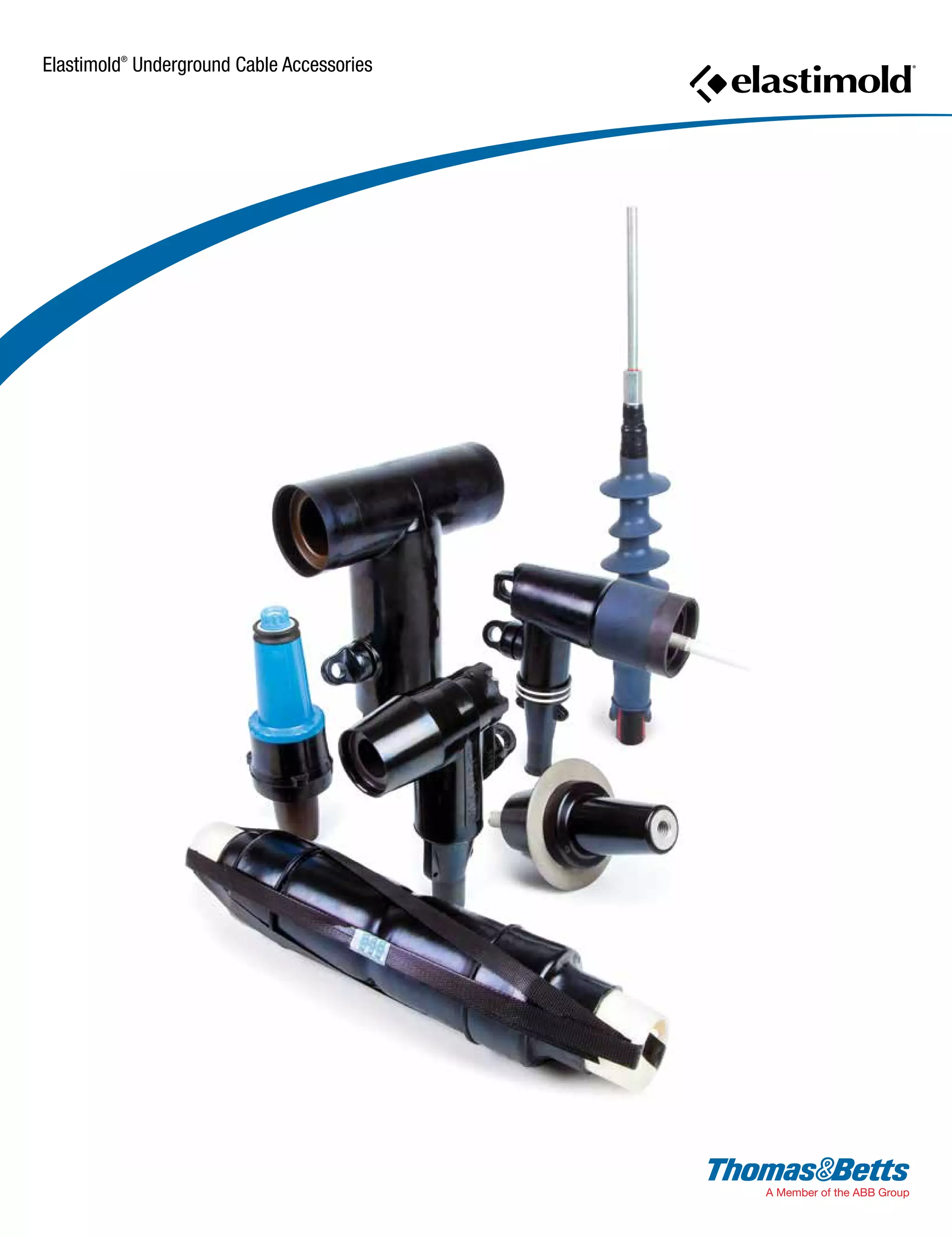
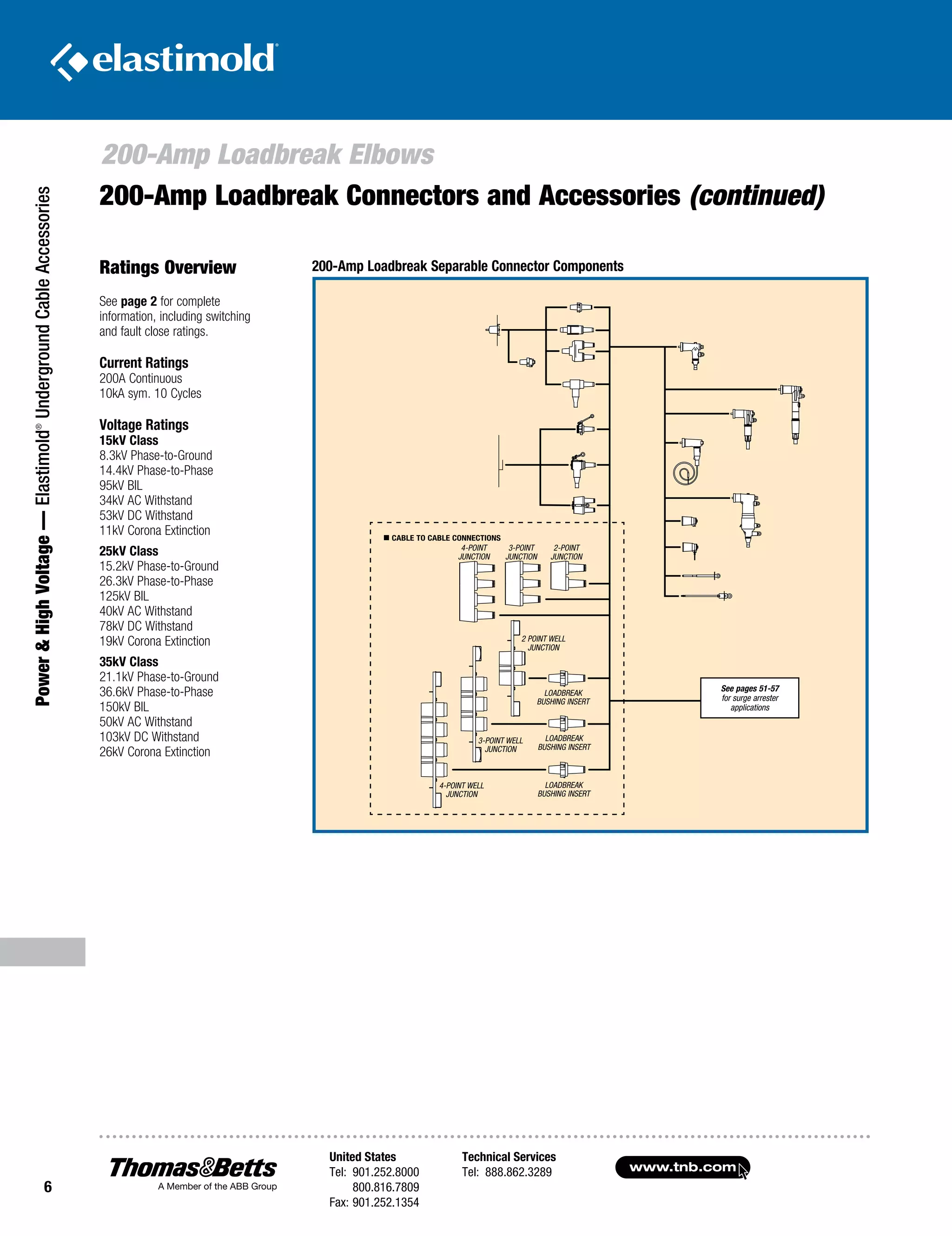
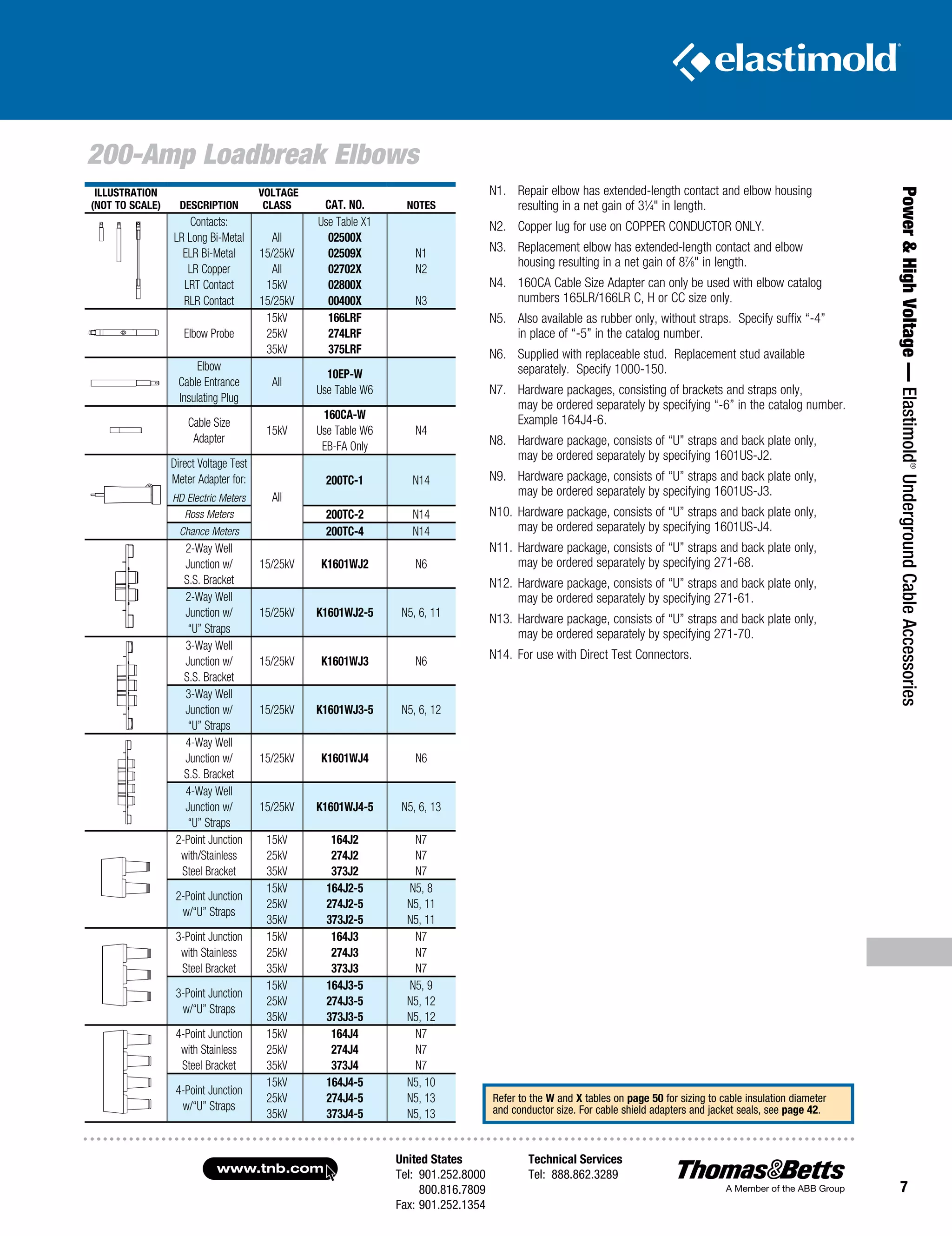
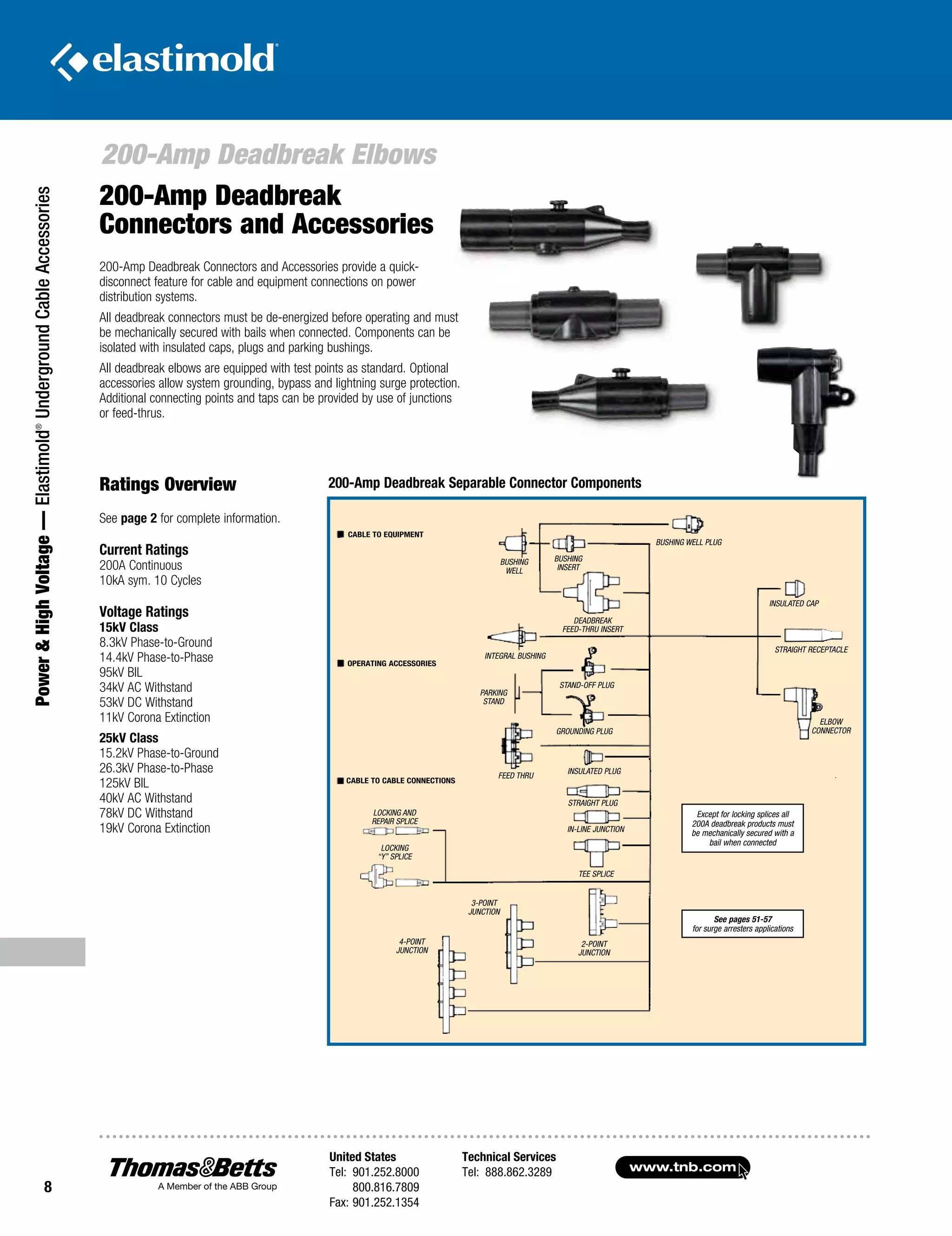
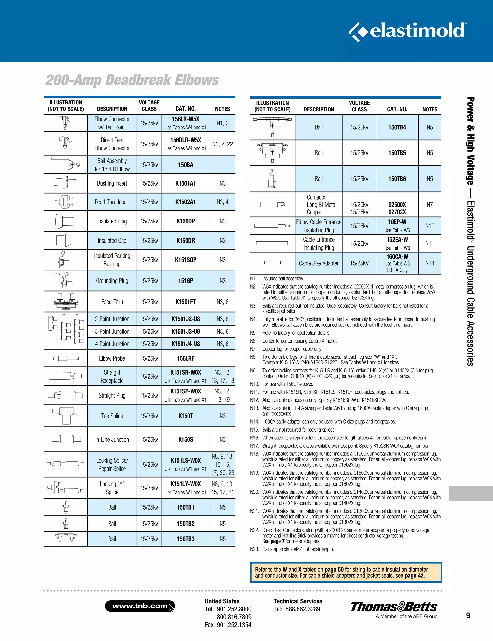
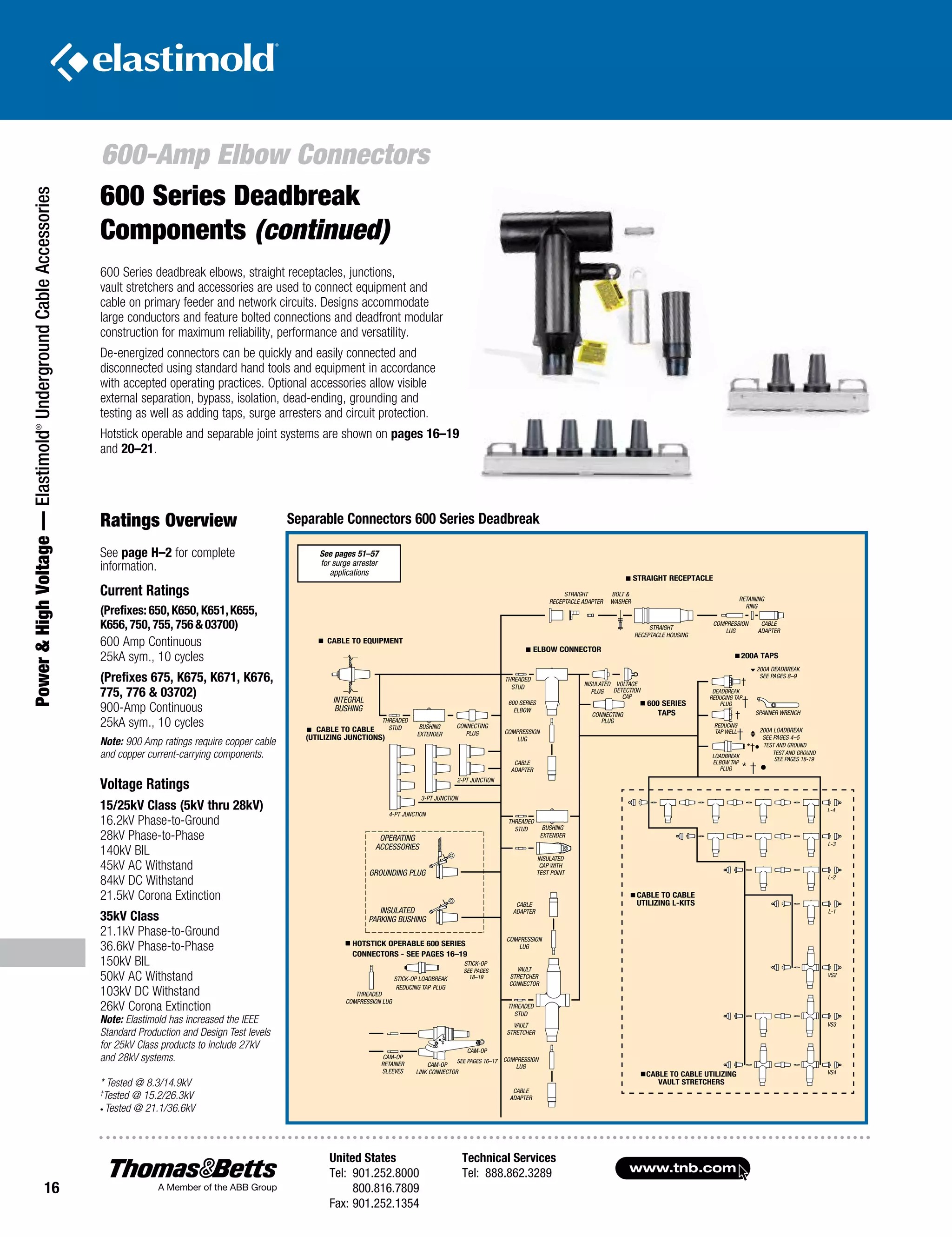
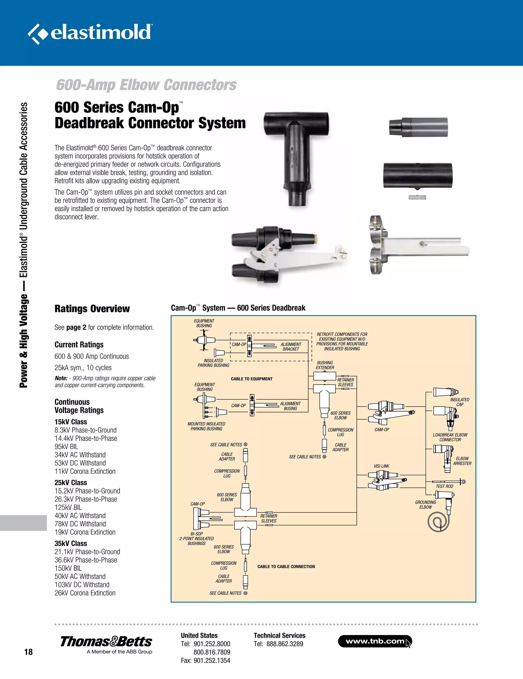
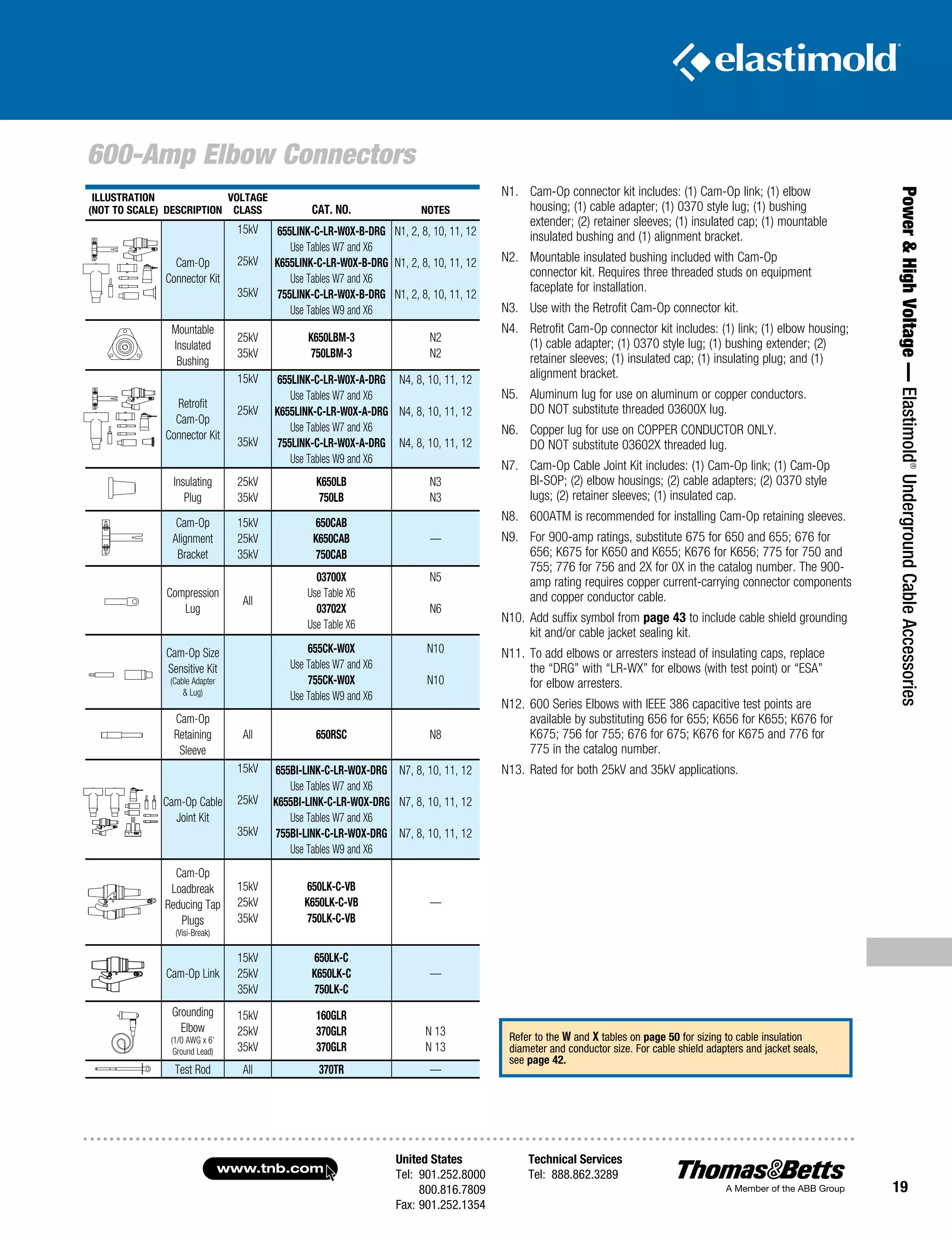
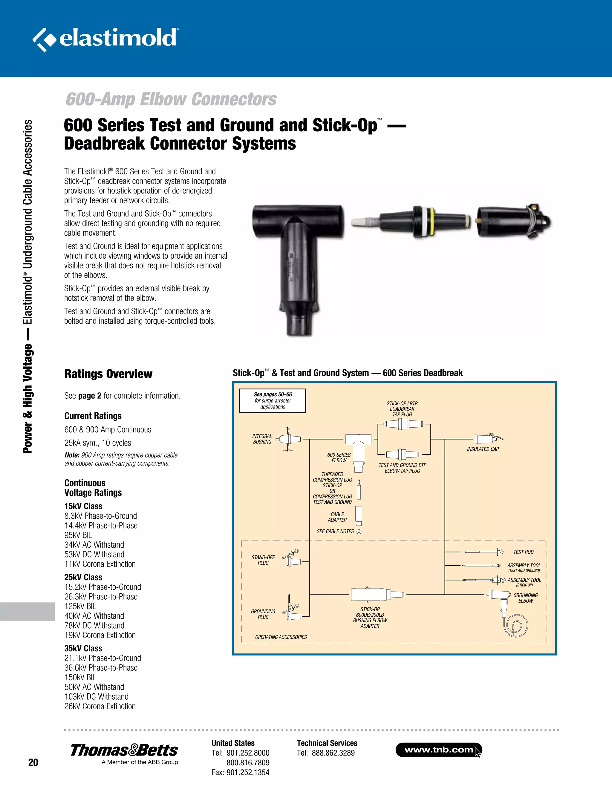
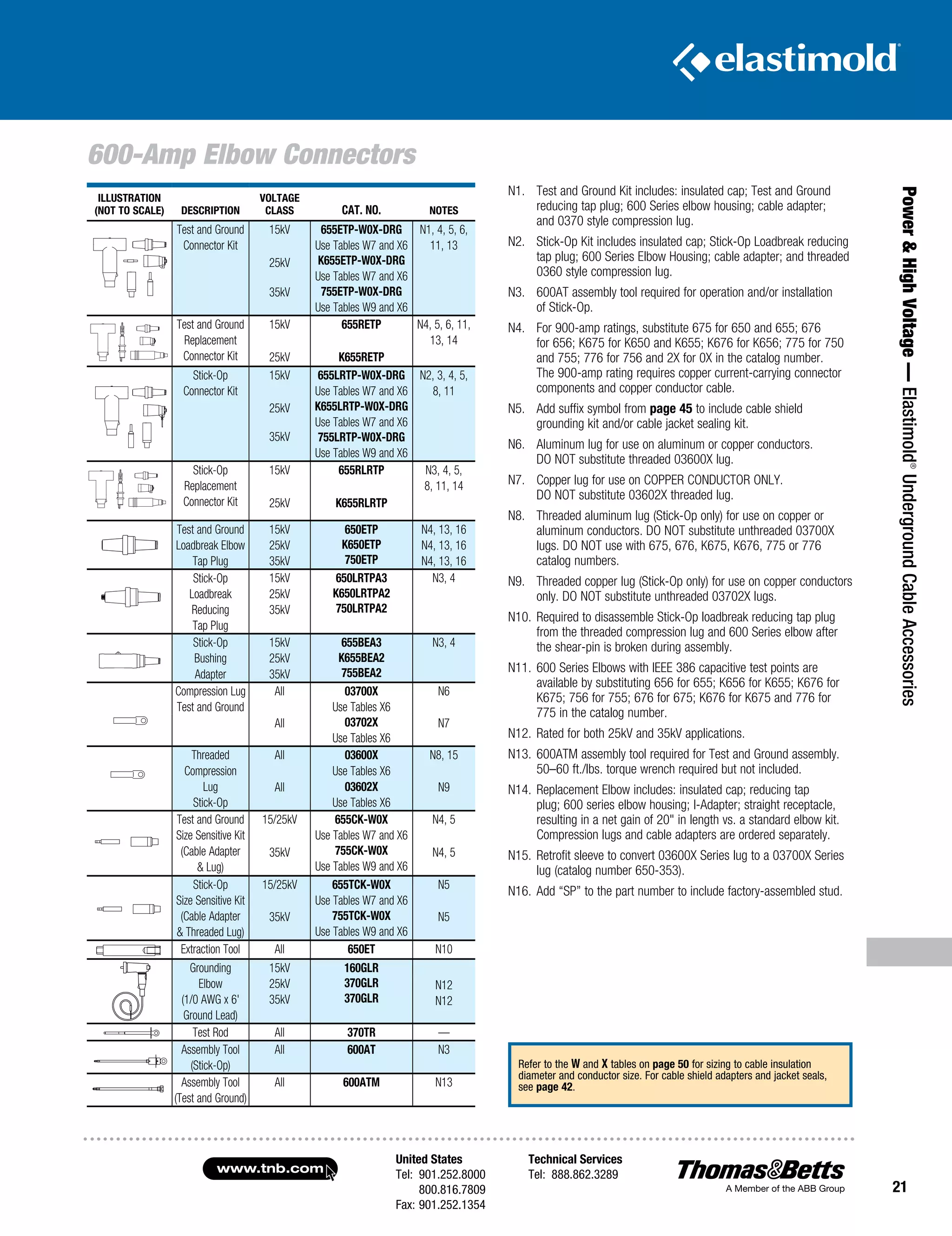
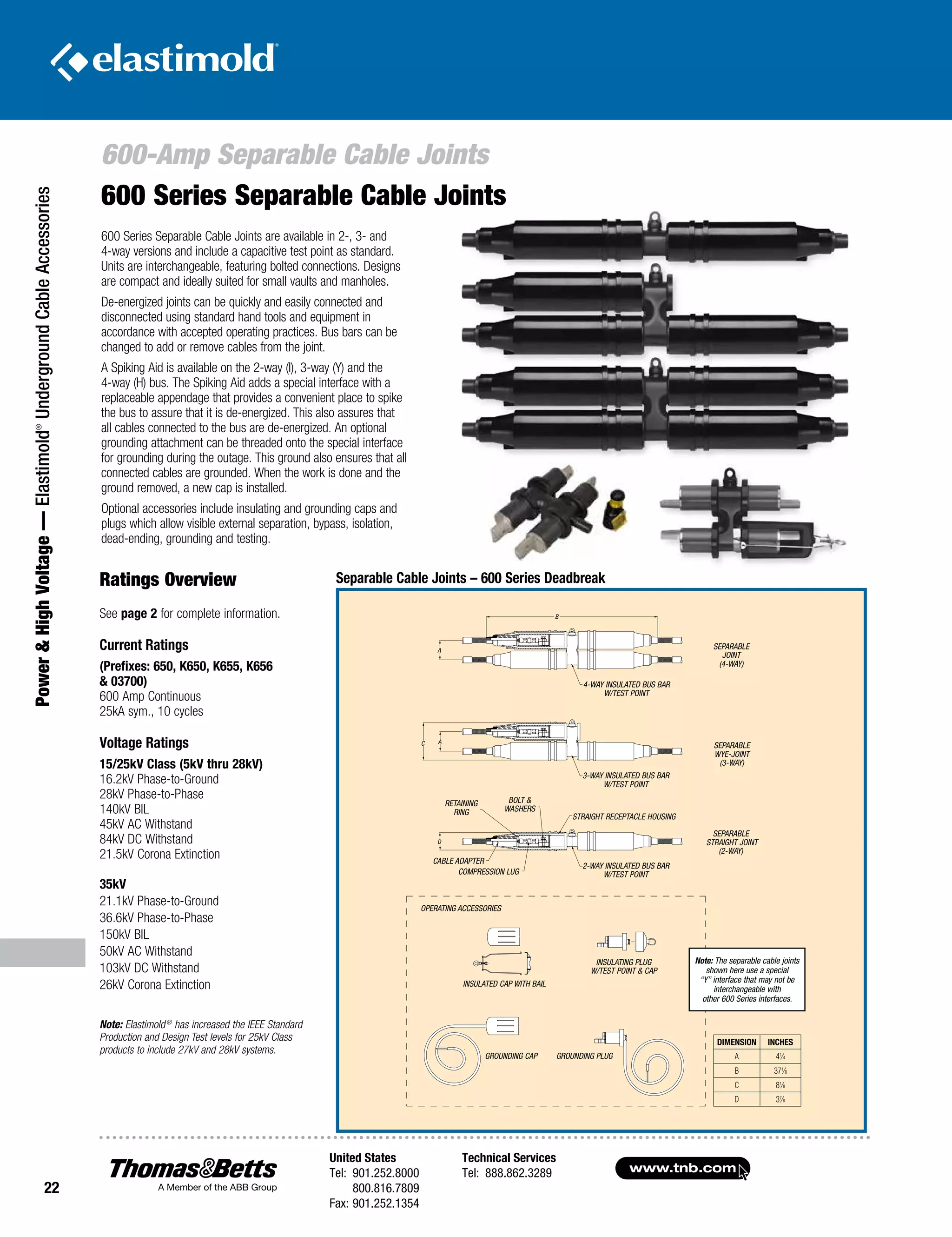
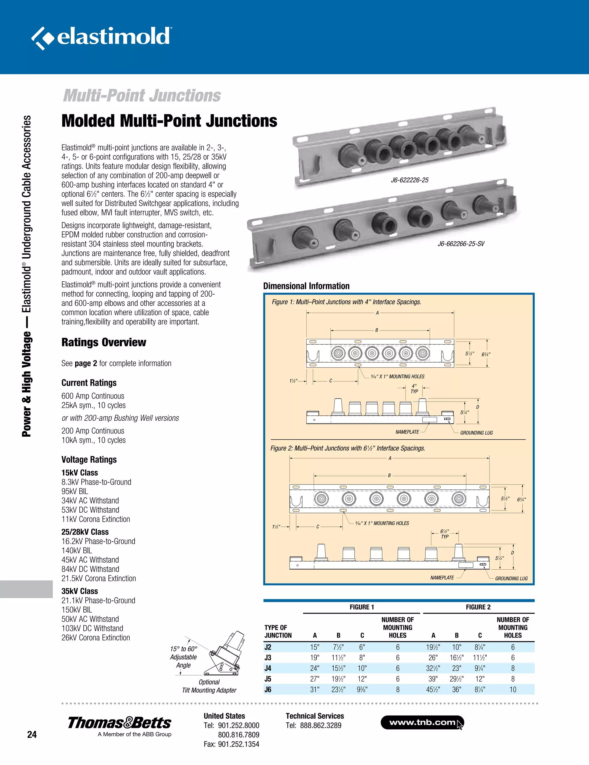
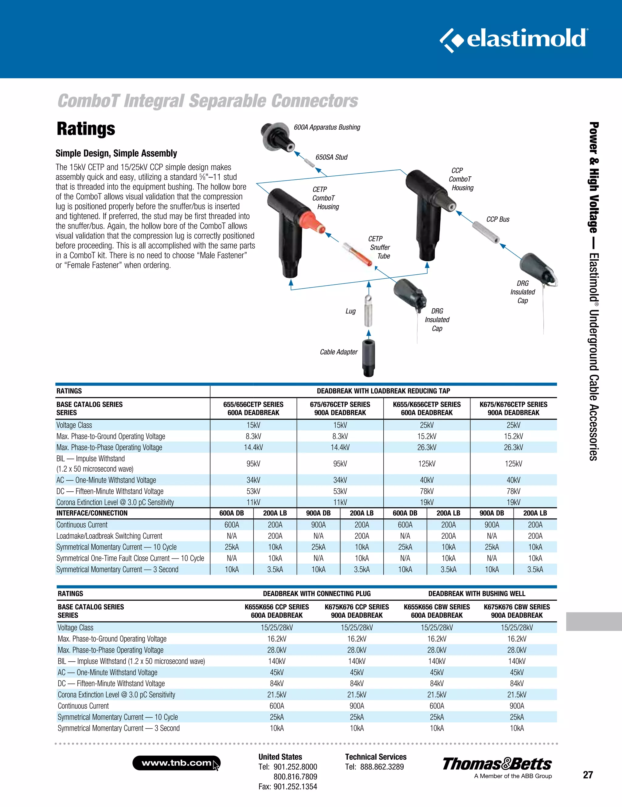
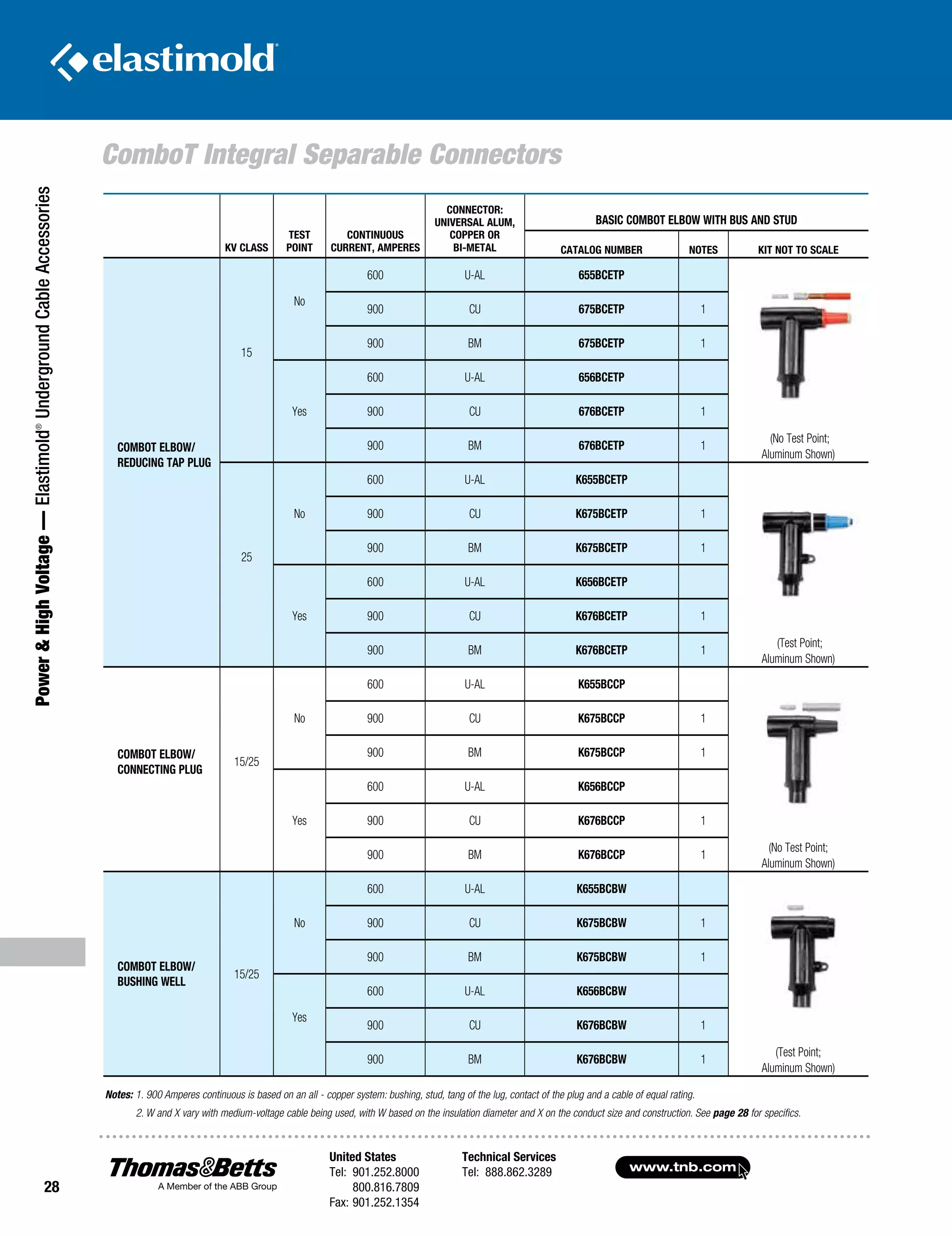
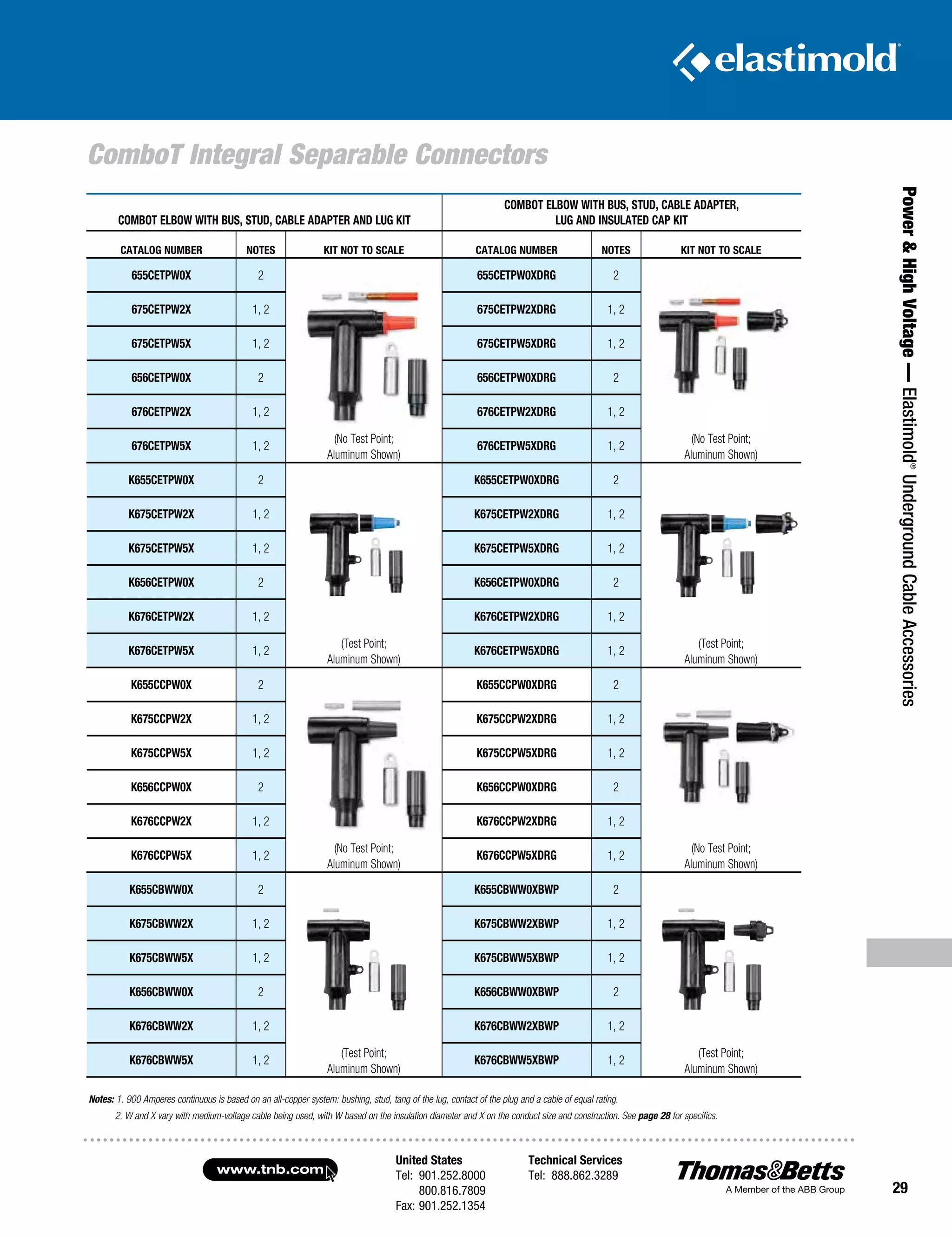
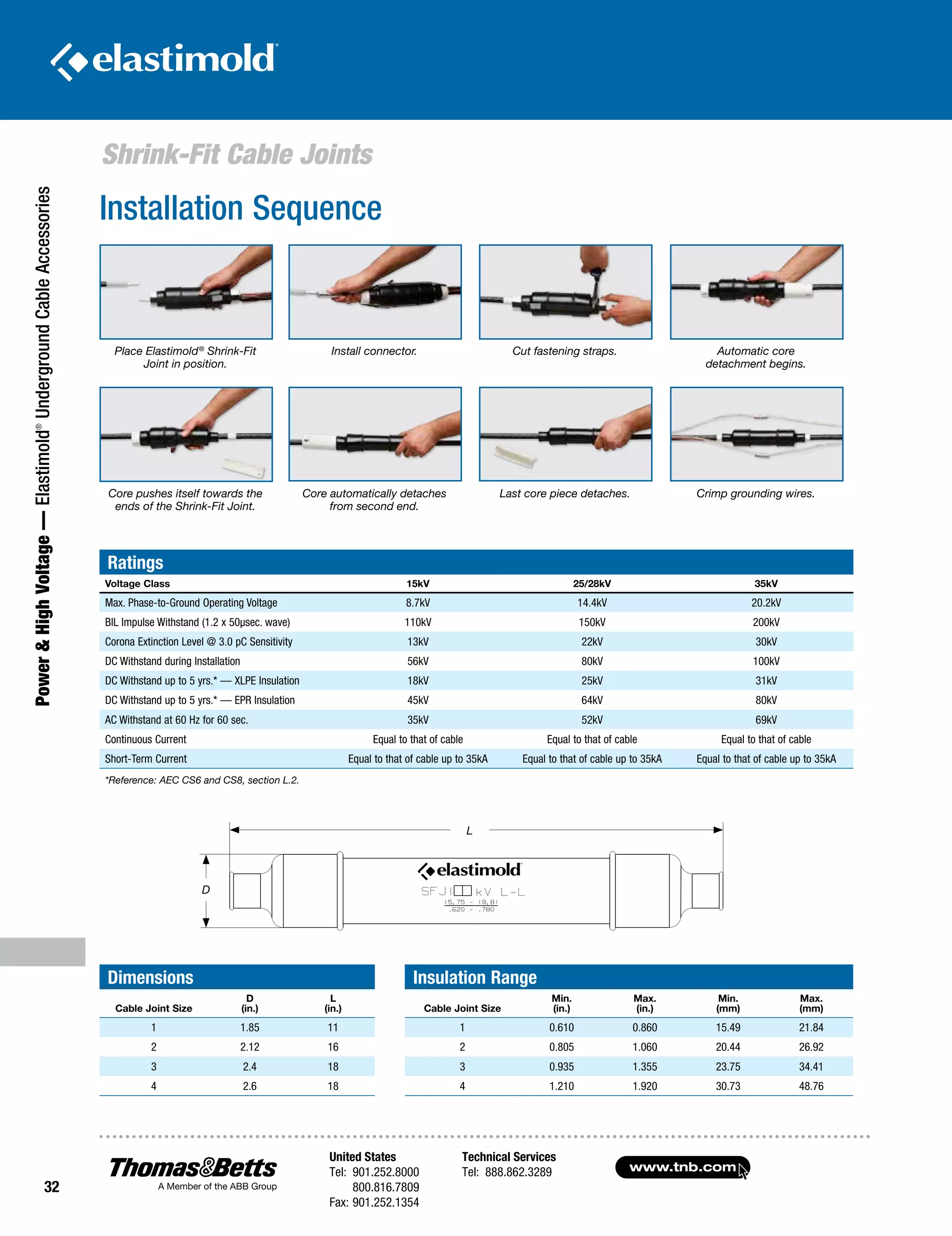
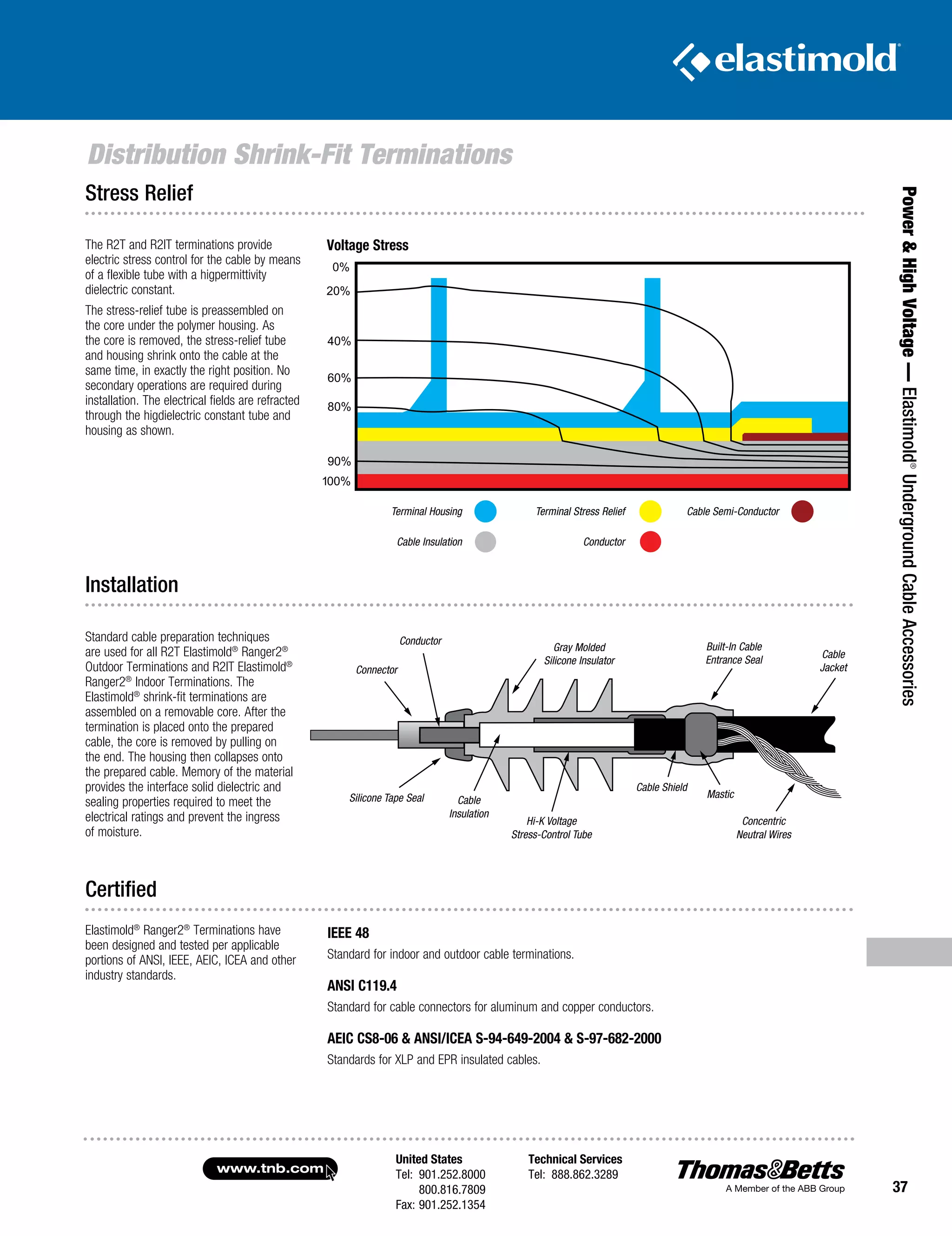
Elastimold®
Underground Cable Accessories
Renewable Energy
Power Generation
Transmission and Distribution
At T&B, we’re committed to:
•	 Products which provide solutions to your electrical needs
•	Convenience of single-order, single-shipment
to your site for thousands of stocking items
•	Expert local point of contact for clear, consistent
information regarding training, codes and standards
•	Quality brands that have proven themselves over time
•	Inventive design and manufacture of problem-solving products
•	Offering a best-of-class warranty and returns policy
•	Uniform carton labeling with additional bar-coding
for convenient inventory management
•	Nationwide network of stocking electrical distributors
•	Outstanding customer service capability
•	Supplying you with the right products, convenient
packaging, on-time delivery and competitive pricing
We deliver the solutions that make your job easier and offer the power to bring
it all together in one package. Call us today and let us help you profit from
sourcing your electrical products from the leader, Thomas & Betts.
Choose Thomas & Betts and connect
to the power you need.
For over 100 years, Thomas & Betts has successfully applied innovative
design and manufacturing techniques to meet the changing needs of the
marketplace. Today, we offer more than 100,000 electrical components
and systems to terminate, connect, fasten, protect and identify wires,
components and raceway. Our vast offering makes us one of the largest
and best sources of electrical components in North America.
United States
Tel: 901.252.8000
800.816.7809
Fax: 901.252.1354
Technical Services
Tel: 888.862.3289www.tnb.com
i
T&B Services
Quality You Can Trust
Trust T&B’s dedicated Tool Services Department to answer all questions
regarding tool applications, repair, warranties, sales/lease/rental and technical
information. Ask about our specialized services, including customer/sales training,
demos and calibration/certification of tools.
Tool Services
1-800-284-TOOL
Immediate, Knowledgeable Assistance
Every Thomas & Betts Customer Service Representative is right where the action
is — surrounded by all the support and information they need to answer your
questions and fill your orders faster than ever. Your calls and faxes are automatically
routed to Customer Service Specialists who personally serve your account and can
answer questions about products, order status, price and availability, and other
service-related inquiries.
Phone: 1-800-816-7809
Fax: 1-800-816-7810
Email: generalcustomerserviceteam@tnb.com
Customer Service
1-800-816-7809
Over 170 Years of Industry Experience
Meeting and exceeding our customers’ expectations is a fundamental goal of Thomas
& Betts. Call our Technical Services Department and talk LIVE to an expert who’ll
answer questions and concerns regarding all aspects of our products and services.
Our experienced and knowledgeable staff is second to none in the industry!
Technical Services
1-888-862-3289
i
www.tnb.com
United States
Tel: 901.252.8000
800.816.7809
Fax: 901.252.1354
Technical Services
Tel: 888.862.3289
ii
T&B Online Support
Thousands of Products at Your Fingertips
U.S. contractors and specifiers have made our web catalog their number
one stop. Users can search for technical information by catalog number,
UPC code, competitor number, keyword search, product category and/or
brand. Having found the item(s) they are searching for, they can then use
our Where To Buy function to locate a T&B local distributor and/or other
support services.
Web Catalog
www.tnb.com/webcatalog
T&B Access®
is a global sales tool for our distributor partners, offering:
T&B Access
®
tnbaccess.tnb.com
All of these tools and more are available online 24 hours a day – 7 days a week,
without having to make a single phone call. Multi-lingual options are available in English,
French and Spanish. T&B Access®
now serves over 10,000 satisfied customer users
at over 3,500 locations every month.
•	 Quote Requests
•	 Stock Checks
•	 Pricing Inquiries
•	 Cross Reference
•	 Order Entry
•	 Order Resolution
•	 Shipping Status
•	 Document Look-Up
•	 Automatic Order Receiving
•	 Item History Search
•	 Multiple-Location User Search
•	 Context-Sensitive Help
•	 Shipping Confirmations
•	 Tracking Data
•	Expediting
•	 Returns Processing
•	 Quality Issues
•	 Customer Report Cards
•	 Web Catalog Look-Up
Elastimold
®
Underground
Cable Accessories
In this section...
Elastimold®
Underground Cable Accessories
Overview....................................................................................2–3
200-Amp Loadbreak Elbows.......................................................4–7
200-Amp Deadbreak Elbows......................................................8–9
600-Amp Elbow Connectors................................................... 10-21
600-Amp Separable Cable Joints............................................ 22-23
Multi-Point Junctions.............................................................. 24-25
ComboT Integral Separable Connectors.................................. 26-30
Permanent Distribution Cable Joints....................................... 34-35
Shrink-Fit Cable Joints............................................................ 31-33
Distribution Shrink-Fit Terminations........................................ 36-42
Pre-Molded Terminations..............................................................43
Cable Shield Adapters and Jacket Seals................................. 44-45
Equipment Bushings.....................................................................46
Medium-Voltage Cable Accessories
Technical Information............................................................. 47-52
Shielded Surge Arresters........................................................ 53-59
Transmission Cable Joints...................................................... 60-63
Transmission Cable Terminations........................................... 64-65
Transmission Cable Accessories Installation Tools........................66
Transmission Cable Accessories Technical Information.................67
L-Kits and Vault Stretcher Kits Ordering Information......................68
www.tnb.com
United States
Tel: 901.252.8000
800.816.7809
Fax: 901.252.1354
Technical Services
Tel: 888.862.3289
2
Overview
Power& HighVoltage—Elastimold®
UndergroundCableAccessories
Elastimold®
Separable Connectors, Cable Joints, Cable Terminators
and other cable accessory products have been designed and tested per
applicable portions of IEEE, ANSI and other industry standards including:
•	 IEEE 386™
Standard for Separable Connectors
•	 IEEE 404™
Standard for Cable Joints and Splices
•	 IEEE 48™
Standard for Cable Terminations
•	 IEEE 592™
Standard for Exposed Semiconducting Shields
•	ANSI C119.4 Standard for Copper and Aluminum Conductor
Connectors
•	AEIC CS8 Standards for XLP and EPR Insulated Cables
•	ICEA S-94-649-2004 and S-97-682-2000 Standard for
Cables Rated 5,000 – 46,000 Volts
Cable Joints And Terminations Ratings
Refer to the pages listed below for rating information:
•	PCJ™
Cable Joints, page 32
•	 SFJ Shrink Fit™
Cable Joints, page 29
•	 Cable Terminations, page 34
Separable Connector Ratings
The following chart shows voltage and current ratings which apply to all
Separable Connectors including 200-Amp Loadbreak, 200-Amp Deadbreak
and 600 Series Deadbreak products. The next chart shows switching and
fault close ratings which only apply to 200-Amp Load-Break Connectors.
Application Information:
1.	Load-Break connectors are designed and rated for use on grounded
WYE systems. For application on ungrounded WYE or delta systems,
the next higher voltage class product is recommended. Examples: 5kV
ungrounded: use 15kV class products; 15kV ungrounded: use 25kV
class products; 25kV ungrounded: use 35kV class products.
2.	Products are designed and constructed for all applications including
padmount, subsurface, vault, indoor, outdoor, direct sunlight, direct
buried and continuously submerged in water.
3.	Products are designed and rated for ambient temperatures of -40° C
to +65° C. It is recommended that loadbreak connectors be hotstick
operated at -20° C to +65° C ambient temperature range and at
altitudes not exceeding 6000 feet.
Voltage and Current Ratings
15kV CLASS
RATINGS
25kV CLASS
RATINGS
35kV CLASS
RATINGS
Operating Voltage
Maximum line-to-ground
(See Application Info Note 1)
8.3kV 15.2kV 21.1kV
BIL
Impulse withstand 1.2 x 50
microsecond wave
95kV 125kV 150kV
Withstand Voltage
AC One Minute
DC Fifteen Minute
34kV
53kV
40kV
78kV
50kV
103kV
Corona Extinction Level
@ 3pC Sensitivity 11kV 19kV 26kV
200-Amp Products
Continuous Current: Symmetrical
Momentary Current:
600 Series Products Continuous
Current
Symmetrical Momentary Current:
200 Amp
10kA sym, 10 cycle duration*
600 and 900 Amp
25kA sym, 10 cycle duration*
* Designed for 90° C maximum continuous operating temperature.
Switching and Fault Close Ratings
LOADMAKE/LOADBREAK
SWITCHING FAULT CLOSE
15kV
CLASS
RATINGS
• 1ø and 3ø circuits 8.3kV line
to ground, 14.4kV max. across
open contacts
• 10 loadmake/break operations
at 200 Amps max. with 70 to 80%
lagging power factor
1 fault close operation at 8.3kV
or 14.4kV; 10,000 amps RMS sym;
10 cycles (.17 sec.) 1.3 max. asym
factor applies to new or used mating
parts (up to maximum designated
switching operations)
25kV
CLASS
RATINGS
• 1ø and 3ø circuits 15.2kV line
to ground, 26.3kV max. across
open contacts
• 10 loadmake/break operations
at 200 Amps max. with 70 to 80%
lagging power factor
1 fault close operation at 15.2kV
or 26.3kV; 10,000 amps RMS sym;
10 cycles (.17 sec.) 1.3 max. asym
factor applies to new or used mating
parts (up to maximum designated
switching operations.)
35kV
CLASS
RATINGS
• 1ø and 3ø circuits 21.1kV line
to ground, 36.6kV max. across
open contacts.
• 10 loadmake/break operations
at 200 Amps max. with 70 to 80%
lagging power factor.
1 fault close operation at 21.1kV
or 36.6kV; 10,000 amps RMS sym;
10 cycles (.17 sec.) 1.3 max. asym
factor applies to new or used mating
parts (up to maximum designated
switching operations)
United States
Tel: 901.252.8000
800.816.7809
Fax: 901.252.1354
Technical Services
Tel: 888.862.3289www.tnb.com
3
Power HighVoltage—Elastimold®
UndergroundCableAccessories
Overview
IEEE Standard 386 defines the specific interface dimensions that 200 Amp
and 600 Series elbows, inserts, junctions, equipment bushings and any
mating components must conform to ensure interchangeability. The table below
provides information concerning the types of interfaces supplied by Elastimold®
for various applications and is useful to ensure proper matching of components.
Standard Interfaces for Separable Connectors,
Components and Equipment Bushings
Note: 1. Elastimold®
uses Fig. 7 interface for both 25 and 35kV applications.
BUSHING INTERFACE
VOLTAGE
CLASS
INTERFACE
DESCRIPTION
STANDARD NO.
FIGURE NO.
200-AMP DEEPWELL
EQUIPMENT BUSHING
15kV, 25kV
and 35kV
200-Amp Bushing
Well Interface
8.3kV, 15.2kV and, 21.1kV
IEEE
386-2001
Fig. 3
200-AMP LOADBREAK INSERT 15kV 200-Amp Loadbreak
8.3kV and 8.3kV/14.4kV
IEEE
386-2001
Fig. 5
200-AMP LOADBREAK INSERT 25kV 200-Amp Loadbreak
15.2kV and 15.2kV/26.3kV
IEEE
386-2001
Fig. 7, Note 1
200-AMP LOADBREAK INSERT 35kV 200-Amp Loadbreak
Interface No. 2
21.1kV and 21.1kV/36.3kV
IEEE
386-2001
Fig. 7, Note 1
200-AMP DEADBREAK INSERT 15kV and 25kV 200-Amp Deadbreak
8.3kV and 15.2kV
IEEE
386-2001
Fig. 4
600 SERIES EQUIPMENT BUSHING 15kV and 25kV 600-Amp Deadbreak
Interface No.1
8.3kV and 15.2kV
IEEE
386-2001
Fig.11
600 SERIES EQUIPMENT BUSHING 35kV 600-Amp Deadbreak
Interface No.1
21.1kV
IEEE
386-2001
Fig.13
A
C
D
E
F
G
B
A
C
D
E
F
G
B
www.tnb.com
United States
Tel: 901.252.8000
800.816.7809
Fax: 901.252.1354
Technical Services
Tel: 888.862.3289
4
200-Amp Loadbreak Elbows
Power HighVoltage—Elastimold®
UndergroundCableAccessories
CABLE TO EQUIPMENT
CONNECTIONS
OPERATING ACCESSORIES
BUSHING WELL
PLUG
BUSHING WELL
LOADBREAK
BUSHING INSERT
EXTENDED BUSHING INSERT
LOADBREAK
FEED-THRU INSERT
BOLTED
ELBOW
W/TAP
INSULATED PARKING
BUSHING
GROUNDING
PLUG
PARKING
STAND
FEED THRU
See pages 51-57
for surge arrester
applications
LOADBREAK ELBOW CONNECTOR WITH
OR WITHOUT TEST POINT
SEE CABLE NOTES
SEE CABLE NOTES
SEE CABLE NOTES
GROUNDING
ELBOW
REPAIR
ELBOW
REPLACEMENT
ELBOW
FUSED ELBOW
INSULATED CAP
INSULATED CAP
WITH GROUND
TEST ROD
ASSEMBLY TOOL
200-Amp Loadbreak
Connectors and Accessories
200-Amp Loadbreak Connectors and Accessories provide a
convenient method to connect/disconnect cable and equipment on
power distribution systems. Loadbreak elbows include provisions for
energized operation using standard hotstick tools, allowing loadmake/
break operation and a visible disconnect. Components can be isolated
with insulated caps, plugs and parking bushings.
Optional accessories allow system grounding, testing, bypass, surge
protection and current limiting fusing. Additional connecting points
and taps can be provided by use of junctions or feed-thrus.
Ratings Overview
See page 2 for complete
information, including switching
and fault close ratings.
Current Ratings
200A Continuous
10kA sym. 10 Cycles
Voltage Ratings
15kV Class
8.3kV Phase-to-Ground
14.4kV Phase-to-Phase
95kV BIL
34kV AC Withstand
53kV DC Withstand
11kV Corona Extinction
25kV Class
15.2kV Phase-to-Ground
26.3kV Phase-to-Phase
125kV BIL
40kV AC Withstand
78kV DC Withstand
19kV Corona Extinction
35kV Class
21.1kV Phase-to-Ground
36.6kV Phase-to-Phase
150kV BIL
50kV AC Withstand
103kV DC Withstand
26kV Corona Extinction
200-Amp Loadbreak Separable Connector Components
United States
Tel: 901.252.8000
800.816.7809
Fax: 901.252.1354
Technical Services
Tel: 888.862.3289www.tnb.com
5
Power HighVoltage—Elastimold®
UndergroundCableAccessories
200-Amp Loadbreak Elbows
ILLUSTRATION
(NOT TO SCALE) DESCRIPTION
VOLTAGE
CLASS CAT. NO. NOTES
Grounding Plug
(1/0 AWG x 6'
Ground Lead)
15kV
25kV
161GP
272GP
Grounding
Elbow
(1/0 AWG x 6'
Ground Lead)
15kV
25/35kV
160GLR
370GLR N12
Feed-Thru
15kV
25kV
35kV
35kV
164FT
274FT
371FT
373FT
N6, N18
Feed-Thru
Vertical
15kV
25kV
35kV
164FTV
274FTV
373FTV
Adjustable Bracket
2-Point Feed-Thru
15kV
25kV
35kV
164FT2-AB
274FT2-AB
373FT2-AB
N22
N22
N22
Adjustable Bracket
3-Point Feed-Thru
15kV
25kV
35kV
164FT3-AB
274FT3-AB
373FT3-AB
N22
N22
N22
Adjustable Bracket
4-Point Feed-Thru
15kV
25kV
35kV
164FT4-AB
274FT4-AB
373FT4-AB
N22
N22
N22
Feed-Thru Well 15/25kV
K1601WFT
Feed-Thru Well Vertical 15/25kV
K1601WFTV
Insulated Parking
Bushing
15kV
25kV
35kV
161SOP
272SOP
372SOP
N20
Insulated Parking
Bushing
15kV
25kV
164SOP
274SOP
N22
N22
Test Rod All 200AT
Bushing Well
Plug
15/25kV
35kV
276BWP
M276BWP
Assembly Tool All 370TR N8
ILLUSTRATION
(NOT TO SCALE) DESCRIPTION
VOLTAGE
CLASS CAT. NO. NOTES
Elbow
Connector
15kV
25kV
35kV
165LR-W5X
Use Tables W1 and X1
275LR-W5X
Use Tables W16 and X1
375LR-W5X
Use Tables W3 and X2
N2, 3, 4, 5
N2, 3, 4, 5
N2, 3, 5
Elbow
Connector
w/ Test Point
15kV
25kV
35kV
166LR-W5X
Use Tables W1 and X1
276LR-W5X
Use Tables W16 and X1
376LR-W5X
Use Tables W3 and X2
N2, 3, 4, 5, 23
N2, 3, 4, 5, 23
N2, 3, 5, 23
Jacket Seal
Elbow
Connector
15kV
25kV
165LRJS-W5X
Use Tables W1 and X1
275LRJS-W5X
Use Tables W16 and X1
N2, 19
N2, 19
Jacket Seal
Elbow
Connector
w/ Test Point
15kV
25kV
166LRJS-W5X
Use Tables W1 and X1
276LRJS-W5X
Use Tables W16 and X1
N2, 19, 23
N2, 19, 23
Repair Elbow
Connector
15kV
25kV
167ELR-W5X
Use Tables W5 and X1
273ELR-W5X
Use Tables W5 and X1
N5, 10, 18
N5, 10, 18
Repair Elbow
Connector
w/ Test Point
15kV
25kV
168ELR-W5X
Use Tables W5 and X1
274ELR-W5X
Use Tables W5 and X1
N5, 10, 18, 23
N5, 10, 18, 23
Replacement
Elbow
15kV
25kV
167RLR-W5X
Use Tables W4 and X1
273RLR-W5X
Use Tables W2 and X1
N5, 11, 13
N5, 11, 13
Replacement
Elbow
w/ Test Point
15kV
25kV
168RLR-W5X
Use Tables W4 and X1
274RLR-W5X
Use Tables W2 and X1
N5, 11, 13, 23
N5, 11, 13, 23
Direct Test
Elbow
Connector
15kV
25kV
167DLR-W5X
Use Tables W4 and X1
273DLR-W5X
Use Tables W2 and X1
N2, 5, 21
N2, 5, 21
Direct Test Repair
Elbow
Connector
15kV
25kV
167DELR-W5X
Use Tables W5 and X1
273DELR-W5X
Use Tables W5 and X1
N5, 10, 18, 21
N5, 10, 18, 21
Direct Test
Repair Elbow
Connector
w/Test Point
15kV
25kV
168DELR-W5X
Use Tables W5 and X1
274DELR-W5X
Use Tables W5 and X1
N5, 10, 18,
21, 23
N5, 10, 18,
21, 23
Fused Elbow
(Full Range
Current Limiting)
15kV
25kV
168FLR W0X
274FLR W0X
N23
N23
Bolted Elbow
w/ Tap
15kV
167LRT-W5X
Use Tables W4 and X1
N17
Bushing Insert
15kV
25kV
35kV
35kV
1601A4
2701A4
3701A4
3701A3
N4, 8
N4, 8
N6, 20
20
Extended
Bushing
Insert
15kV
25kV
1601EA4
2701EA4
N8
N8
Feed-Thru
Insert
15kV
25kV
35kV
1602A3R
2702A1
3702A1
N16
N16
N6, 16
Insulated Cap
15kV 160DR N9
Insulated Cap
w/ Ground
15kV
15kV
25kV
35kV
160DRG
167DRG
273DRG
375DRG
N9
N7, 9
N7, 9
N7, 9
Insulated Cap
w/ Ground and
Test Point
15kV
25kV
35kV
168DRG
274DRG
376DRG
N7
N7
N7
Refer to the W and X tables on page 50 for sizing to cable insulation diameter
and conductor size. For cable shield adapters and jacket seals, see page 42.
N1.	Copper lug for use on COPPER CONDUCTOR ONLY.
N2.	W5X indicates that the catalog number includes 02500X long bi-metal compression lug as standard.
For an all-copper lug, replace W5X with W2X in Table X1 to specify the all-copper 02702X lug.
N3.	Also available as housing only. Specify: 165BLR-W; 275BLR-W;
375BLR-W; 166BLR-W; 276BLR-W; 376BLR-W.
N4.	Also available as elbow/insert combination. Specify: 165A4-WX;
275A4-WX; 166A4-WX; 276A4-WX.
N5.	Also available with 200ECS jacket seal included. Add - “S” suffix to catalog number.
N6.	Rated for single-phase applications only.
N7.	Equipped with insulated cuff.
N8.	Includes internal torquing feature using 200AT Assembly Tool.
N9.	Also available without probe. Specify “A” suffix - Example: 273DRGA.
N10.	Repair elbow has extended length contact and elbow housing resulting in a net gain of
31
⁄4 in length.
N11.	Replacement elbow has extended-length contact and elbow housing resulting
in a net gain of 87
⁄8 in length.
N12.	Rated for 25kV thru 35kV applications.
N13.	 Includes long bi-metal contact 00400X.
N14.	160CA Cable Size Adapter can only be used with elbow part numbers 165LR/166LR C size only.
N16.	Fully rotatable for 360° positioning. Includes bail assembly to secure feed-thru insert to bushing well.
N17.	Includes 02800X bi-metal contact.
N18.	Includes 02509X long bi-metal contact.
N19.	Includes built-in jacket seal. Also available as housing only — specify: 165BLRJS-W, 166BLRJS-W,
275BLRJS-W or 276LRJS-W. Also available as elbow/insert combination — specify: 165JSA4-W5X,
166JSA4-W5X, 275JSA4-W5X or 276JSA4-W5X.
N20.	 Includes a black vent ring.
N21.	 Direct Test Connectors, along with a 200TC-X series meter adapter, a properly rated
	 voltage meter and Hot-line Stick provide a means for direct conductor voltage testing.
N22.	 With stainless steel bracket.
N23.	 Test Point Cap catalog number 156-7
N24. Add suffix “-SS” for stainless steel bracket.
www.tnb.com
United States
Tel: 901.252.8000
800.816.7809
Fax: 901.252.1354
Technical Services
Tel: 888.862.3289
6
200-Amp Loadbreak Elbows
Power HighVoltage—Elastimold®
UndergroundCableAccessories
200-Amp Loadbreak Separable Connector Components
CABLE TO CABLE CONNECTIONS
4-POINT
JUNCTION
3-POINT
JUNCTION
2-POINT
JUNCTION
2 POINT WELL
JUNCTION
3-POINT WELL
JUNCTION
4-POINT WELL
JUNCTION
LOADBREAK
BUSHING INSERT
LOADBREAK
BUSHING INSERT
LOADBREAK
BUSHING INSERT
Ratings Overview
See page 2 for complete
information, including switching
and fault close ratings.
Current Ratings
200A Continuous
10kA sym. 10 Cycles
Voltage Ratings
15kV Class
8.3kV Phase-to-Ground
14.4kV Phase-to-Phase
95kV BIL
34kV AC Withstand
53kV DC Withstand
11kV Corona Extinction
25kV Class
15.2kV Phase-to-Ground
26.3kV Phase-to-Phase
125kV BIL
40kV AC Withstand
78kV DC Withstand
19kV Corona Extinction
35kV Class
21.1kV Phase-to-Ground
36.6kV Phase-to-Phase
150kV BIL
50kV AC Withstand
103kV DC Withstand
26kV Corona Extinction
200-Amp Loadbreak Connectors and Accessories (continued)
See pages 51-57
for surge arrester
applications
United States
Tel: 901.252.8000
800.816.7809
Fax: 901.252.1354
Technical Services
Tel: 888.862.3289www.tnb.com
7
Power HighVoltage—Elastimold®
UndergroundCableAccessories
200-Amp Loadbreak Elbows
ILLUSTRATION
(NOT TO SCALE) DESCRIPTION
VOLTAGE
CLASS CAT. NO. NOTES
Contacts:
LR Long Bi-Metal
ELR Bi-Metal
LR Copper
LRT Contact
RLR Contact
All
15/25kV
All
15kV
15/25kV
Use Table X1
02500X
02509X
02702X
02800X
00400X
N1
N2
N3
Elbow Probe
15kV
25kV
35kV
166LRF
274LRF
375LRF
Elbow
Cable Entrance
Insulating Plug
All
10EP-W
Use Table W6
Cable Size
Adapter
15kV
160CA-W
Use Table W6
EB-FA Only
N4
Direct Voltage Test
Meter Adapter for:
HD Electric Meters All
200TC-1 N14
Ross Meters 200TC-2 N14
Chance Meters 200TC-4 N14
2-Way Well
Junction w/
S.S. Bracket
15/25kV K1601WJ2 N6
2-Way Well
Junction w/
“U” Straps
15/25kV K1601WJ2-5 N5, 6, 11
3-Way Well
Junction w/
S.S. Bracket
15/25kV K1601WJ3 N6
3-Way Well
Junction w/
“U” Straps
15/25kV K1601WJ3-5 N5, 6, 12
4-Way Well
Junction w/
S.S. Bracket
15/25kV K1601WJ4 N6
4-Way Well
Junction w/
“U” Straps
15/25kV K1601WJ4-5 N5, 6, 13
2-Point Junction
with/Stainless
Steel Bracket
15kV
25kV
35kV
164J2
274J2
373J2
N7
N7
N7
2-Point Junction
w/“U” Straps
15kV
25kV
35kV
164J2-5
274J2-5
373J2-5
N5, 8
N5, 11
N5, 11
3-Point Junction
with Stainless
Steel Bracket
15kV
25kV
35kV
164J3
274J3
373J3
N7
N7
N7
3-Point Junction
w/“U” Straps
15kV
25kV
35kV
164J3-5
274J3-5
373J3-5
N5, 9
N5, 12
N5, 12
4-Point Junction
with Stainless
Steel Bracket
15kV
25kV
35kV
164J4
274J4
373J4
N7
N7
N7
4-Point Junction
w/“U” Straps
15kV
25kV
35kV
164J4-5
274J4-5
373J4-5
N5, 10
N5, 13
N5, 13
N1.	Repair elbow has extended-length contact and elbow housing
resulting in a net gain of 31
⁄4 in length.
N2.	Copper lug for use on COPPER CONDUCTOR ONLY.
N3.	Replacement elbow has extended-length contact and elbow
housing resulting in a net gain of 87
⁄8 in length.
N4.	160CA Cable Size Adapter can only be used with elbow catalog
numbers 165LR/166LR C, H or CC size only.
N5.	Also available as rubber only, without straps. Specify suffix “-4”
in place of “-5” in the catalog number.
N6.	Supplied with replaceable stud. Replacement stud available
separately. Specify 1000-150.
N7.	Hardware packages, consisting of brackets and straps only,
may be ­ordered separately by specifying “-6” in the catalog number.
Example 164J4-6.
N8.	Hardware package, consists of “U” straps and back plate only,
may be ordered separately by specifying 1601US-J2.
N9.	Hardware package, consists of “U” straps and back plate only,
may be ordered separately by specifying 1601US-J3.
N10.	Hardware package, consists of “U” straps and back plate only,
may be ordered separately by specifying 1601US-J4.
N11.	Hardware package, consists of “U” straps and back plate only,
may be ordered separately by specifying 271-68.
N12.	Hardware package, consists of “U” straps and back plate only,
may be ordered separately by specifying 271-61.
N13.	Hardware package, consists of “U” straps and back plate only,
may be ordered separately by specifying 271-70.
N14.	For use with Direct Test Connectors.
Refer to the W and X tables on page 50 for sizing to cable insulation diameter
and conductor size. For cable shield adapters and jacket seals, see page 42.
www.tnb.com
United States
Tel: 901.252.8000
800.816.7809
Fax: 901.252.1354
Technical Services
Tel: 888.862.3289
8
200-Amp Deadbreak Elbows
Power HighVoltage—Elastimold®
UndergroundCableAccessories
LOCKING AND
REPAIR SPLICE
LOCKING
“Y” SPLICE
FEED THRU
PARKING
STAND
STAND-OFF PLUG
INTEGRAL BUSHING
GROUNDING PLUG
INSULATED PLUG
STRAIGHT PLUG
IN-LINE JUNCTION
TEE SPLICE
BUSHING
WELL
BUSHING
INSERT
BUSHING WELL PLUG
DEADBREAK
FEED-THRU INSERT
3-POINT
JUNCTION
4-POINT
JUNCTION
2-POINT
JUNCTION
CABLE TO EQUIPMENT
OPERATING ACCESSORIES
CABLE TO CABLE CONNECTIONS
200-Amp Deadbreak
Connectors and Accessories
200-Amp Deadbreak Connectors and Accessories provide a quick-
disconnect feature for cable and equipment connections on power
distribution systems.
All deadbreak connectors must be de-­energized before operating and must
be mechanically secured with bails when connected. Components can be
isolated with insulated caps, plugs and parking bushings.
All deadbreak elbows are equipped with test points as standard. Optional
accessories allow system grounding, bypass and lightning surge protection.
Additional connecting points and taps can be provided by use of junctions
or feed-thrus.
Ratings Overview
See page 2 for complete information.
Current Ratings
200A Continuous
10kA sym. 10 Cycles
Voltage Ratings
15kV Class
8.3kV Phase-to-Ground
14.4kV Phase-to-Phase
95kV BIL
34kV AC Withstand
53kV DC Withstand
11kV Corona Extinction
25kV Class
15.2kV Phase-to-Ground
26.3kV Phase-to-Phase
125kV BIL
40kV AC Withstand
78kV DC Withstand
19kV Corona Extinction
200-Amp Deadbreak Separable Connector Components
Except for locking splices all
200A deadbreak products must
be mechanically secured with a
bail when connected
See pages 51-57
for surge arresters applications
INSULATED CAP
STRAIGHT RECEPTACLE
ELBOW
CONNECTOR
United States
Tel: 901.252.8000
800.816.7809
Fax: 901.252.1354
Technical Services
Tel: 888.862.3289www.tnb.com
9
Power HighVoltage—Elastimold®
UndergroundCableAccessories
200-Amp Deadbreak Elbows
ILLUSTRATION
(NOT TO SCALE) DESCRIPTION
VOLTAGE
CLASS CAT. NO. NOTES
Bail 15/25kV 150TB4 N5
Bail 15/25kV 150TB5 N5
Bail 15/25kV 150TB6 N5
Contacts:
Long Bi-Metal
Copper
15/25kV
15/25kV
02500X
02702X
N7
Elbow Cable Entrance
Insulating Plug
15/25kV
10EP-W
Use Table W6
N10
Cable Entrance
Insulating Plug
15/25kV
152EA-W
Use Table W6
N11
Cable Size Adapter 15/25KV
160CA-W
Use Table W6
EB-FA Only
N14
ILLUSTRATION
(NOT TO SCALE) DESCRIPTION
VOLTAGE
CLASS CAT. NO. NOTES
Elbow Connector
w/ Test Point
15/25kV
156LR-W5X
Use Tables W4 and X1
N1, 2
Direct Test
Elbow Connector
15/25kV
156DLR-W5X
Use Tables W4 and X1
N1, 2, 22
Bail Assembly
for 156LR Elbow
15/25kV 150BA
Bushing Insert 15/25kV K1501A1 N3
Feed-Thru Insert 15/25kV K1502A1 N3, 4
Insulated Plug 15/25kV K150DP N3
Insulated Cap 15/25kV K150DR N3
Insulated Parking
Bushing
15/25kV K151SOP N3
Grounding Plug 15/25kV 151GP N3
Feed-Thru 15/25kV K1501FT N3, 6
2-Point Junction 15/25kV K1501J2-U8 N3, 6
3-Point Junction 15/25kV K1501J3-U8 N3, 6
4-Point Junction 15/25kV K1501J4-U8 N3, 6
Elbow Probe 15/25kV 156LRF
Straight
Receptacle
15/25kV
K151SR-W0X
Use Tables W1 and X1
N3, 12,
13, 17, 18
Straight Plug 15/25kV
K151SP-W0X
Use Tables W1 and X1
N3, 12,
13, 19
Tee Splice 15/25kV K150T N3
In-Line Junction 15/25kV K150S N3
Locking Splice/
Repair Splice
15/25kV
K151LS-W0X
Use Tables W1 and X1
N8, 9, 13,
15, 16,
17, 20, 23
Locking “Y”
Splice
15/25kV
K151LY-W0X
Use Tables W1 and X1
N8, 9, 13,
15, 17, 21
Bail 15/25kV 150TB1 N5
Bail 15/25kV 150TB2 N5
Bail 15/25kV 150TB3 N5
N1.	 Includes bail assembly.
N2.	W5X indicates that the catalog number includes a 02500X bi-metal compression lug, which is
rated for either aluminum or copper conductor, as standard. For an all-copper lug, replace W5X
with W2X. Use Table X1 to specify the all-copper 02702X lug.
N3.	Bails are required but not included. Order separately. Consult factory for bails not listed for a
specific application.
N4.	Fully rotatable for 360° positioning. Includes bail assembly to secure feed-thru insert to bushing
well. Elbows bail assemblies are required but not included with the feed-thru insert.
N5.	 Refer to factory for application details.
N6.	 Center-to-center spacing equals 4 inches.
N7.	 Copper lug for copper cable only.
N8.	To order cable legs for different cable sizes, list each leg size “W” and “X”.
Example: K151LY-A1240-A1240-B1220. See Tables W1 and X1 for sizes.
N9.	To order locking contacts for K151LS and K151LY, order 01401X (Al) or 01402X (Cu) for plug
contact. Order 01301X (Al) or 01302X (Cu) for receptacle. See Table X1 for sizes.
N10.	For use with 156LR elbows.
N11.	For use with K151SR, K151SP, K151LS, K151LY receptacles, plugs and splices.
N12.	Also available as housing only. Specify K151BSP-W or K151BSR-W.
N13.	Also available in EB-FA sizes per Table W6 by using 160CA cable adapter with C size plugs
and receptacles.
N14.	 160CA cable adapter can only be used with C size plugs and receptacles.
N15.	Bails are not required for locking splices.
N16.	When used as a repair splice, the assembled length allows 4 for cable­replacement/repair.
N17.	Straight receptacles are also available with test point. Specify K152SR-W0X catalog number.
N18.	W0X indicates that the catalog number includes a 01500X universal aluminum compression lug,
which is rated for either aluminum or copper, as standard. For an all-copper lug, replace W0X with
W2X in Table X1 to specify the all-copper 01502X lug.
N19.	W0X indicates that the catalog number includes a 01600X universal aluminum compression lug,
which is rated for either aluminum or copper, as standard. For an all-copper lug, replace W0X with
W2X in Table X1 to specify the all-copper 01602X lug.
N20.	W0X indicates that the catalog number includes a 01400X universal aluminum compression lug,
which is rated for either aluminum or copper, as standard. For an all-copper lug, replace W0X with
W2X in Table X1 to specify the all-copper 01402X lug.
N21.	W0X indicates that the catalog number includes a 01300X universal aluminum compression lug,
which is rated for either aluminum or copper, as standard. For an all-copper lug, replace W0X with
W2X in Table X1 to specify the all-copper 01302X lug.
N22.	Direct Test Connectors, along with a 200TC-X series meter adapter, a properly rated voltage
meter and Hot-line Stick provides a means for direct conductor voltage testing.
See page 7 for meter adapters.
N23.	 Gains approximately 4 of repair length.
Refer to the W and X tables on page 50 for sizing to cable insulation diameter
and conductor size. For cable shield adapters and jacket seals, see page 42.
www.tnb.com
United States
Tel: 901.252.8000
800.816.7809
Fax: 901.252.1354
Technical Services
Tel: 888.862.3289
10
600-Amp Elbow Connectors
Power HighVoltage—Elastimold®
UndergroundCableAccessories
600 Series deadbreak elbows, straight receptacles, junctions, vault
stretchers and accessories are used to connect equipment and cable
on primary feeder and network circuits. Designs accommodate large
conductors and feature bolted connections and deadfront modular
construction for maximum reliability, performance and versatility.
De-energized connectors can be quickly and easily connected and
disconnected using standard hand tools and equipment in accordance
with accepted operating practices. Optional accessories allow visible
external separation, bypass, isolation, dead-ending, grounding and
testing as well as adding taps, surge arresters and circuit protection.
Hotstick-operable and separable joint systems are shown on
pages 16–19 and 20–21.
Spiking Aid-T
When spiking a medium voltage cable near a stacked T-Body cable
joint, the Elastimold®
Spiking-T is a specially designed product to reduce
outage time and cost. Medium voltage cable is spiked as a means
to assure the circuit is de-energized where there is no sectionalizing
device, direct testing means or provision for grounding. One leg of
stacked T-Body cable joint is spiked/cut with a grounded guillotine type
cable cutter, near the T-Body intersection. Once spiked and proved
de-energized, the cable is re-prepped and a Spiking-T with a lug
extender is assembled and reconnected to the stack. If this stack ever
needs to be spiked again, the Spiking-T provides a convenient place to
spike, no additional cable prep required, just replace the Spiking-T and
the lug extender, reduced outage, reduced cost.
GAD
When your available fault currents exceed 10kA in your underground
systems, the Elastimold®
GAD may be your answer. The Elastimold®
GAD is rated 25kA and installs in the rear interface of a 600 Series
elbow connector (T-Body). The GAD is normally covered and insulated
with an insulating cap that contains capacitive test and a hot stick
operating band. Once the circuit is opened at a disconnecting device,
the test point cap is removed with a hot-stick, and then using an
appropriate capacitive test point meter the test point is checked for
voltage. Then the insulting cap is removed with a hot stick and a high
voltage meter is used to confirm the de-energized state before a ground
cable is connected. No need to remove basic insulating plug, no need
to install temporary grounding adapters, the Elastimold®
GAD is there
when you need it. Also available in a Ball GAD version.
600 Series Deadbreak
Components
United States
Tel: 901.252.8000
800.816.7809
Fax: 901.252.1354
Technical Services
Tel: 888.862.3289www.tnb.com
11
Power HighVoltage—Elastimold®
UndergroundCableAccessories
600-Amp Elbow Connectors
STRAIGHT
RECEPTACLE HOUSING
STRAIGHT RECEPTACLE
STRAIGHT
RECEPTACLE ADAPTER
BOLT 
WASHER
COMPRESSION
LUG
CABLE
ADAPTER
RETAINING
RING
†
†
*†•
SEE PAGES 18–19
SEE PAGES 22–23 FOR
ADDITIONAL JUNCTIONS
SEE PAGES
18–19
HOTSTICK OPERABLE 600 SERIES
CONNECTORS - SEE PAGES 16–19
SEE PAGES 16–17
TEST AND GROUND
CABLE TO EQUIPMENT
ELBOW CONNECTOR
200A TAPS
600 SERIES
TAPS
CABLE TO CABLE
UTILIZING L-KITS
SEE PAGES 14–15
CABLE TO CABLE
(UTILIZING JUNCTIONS)
INTEGRAL
BUSHING
THREADED
STUD BUSHING
EXTENDER
CONNECTING
PLUG
2 PT JUNCTION
3 PT JUNCTION
4 PT JUNCTION
OPERATING
ACCESSORIES
GROUNDING PLUG
INSULATED
PARKING BUSHING
THREADED
COMPRESSION LUG
STICK-OP LOADBREAK
REDUCING TAP PLUG
STICK-OP
CAM-OP
RETAINER
SLEEVES
CAM-OP
LINK CONNECTOR
CAM-OP
CABLE
ADAPTER
COMPRESSION
LUG
VAULT
STRETCHER
THREADED
STUD
VAULT
STRETCHER
CONNECTOR
COMPRESSION
LUG
CABLE
ADAPTER
THREADED
STUD
INSULATED
CAP WITH
TEST POINT
BUSHING
EXTENDER
CABLE
ADAPTER
COMPRESSION
LUG
THREADED
STUD
600 SERIES
ELBOW
INSULATED
PLUG
VOLTAGE
DETECTION
CAP
CONNECTING
PLUG
200A DEADBREAK
SEE PAGES 8–9
200A LOADBREAK
SEE PAGES 4–7
SPANNER WRENCH
DEADBREAK
REDUCING TAP
PLUG
REDUCING
TAP WELL
LOADBREAK
ELBOW TAP
PLUG
CABLE TO CABLE UTILIZING
VAULT STRETCHERS
SEE PAGES 14–15
See pages 51–57
for surge arrester
applications
600 Series Deadbreak
Components
Voltage Ratings
15/25kV Class (5kV thru 28kV)
16.2kV Phase-to-Ground
28kV Phase-to Phase
140kV BIL
45kV AC Withstand
84kV DC Withstand
21.5kV Corona Extinction
35kV Class
21.1kV Phase-to-Ground
36.6kV Phase-to-Phase
150kV BIL
50kV AC Withstand
103kV DC Withstand
26kV Corona Extinction
Note: Elastimold has increased the IEEE
Standard Prod­uction and Design Test levels
for 25kV Class products to include 27kV
and 28kV systems.
* Tested at 8.3/14.9kV
†
Tested at 15.2/26.3kV
• Tested at 21.1/36.6kV
Ratings Overview
See page 2 for complete information.
Current Ratings
(Prefixes: 650, K650, K651, K655, K656, 750, 755,
756  03700)
600 Amp Continuous
25kA sym.,10 cycles
(Prefixes 675, K671, K675, K676, 775, 776  03702)
900 Amp Continuous
25kA sym.,10 cycles
Note: 900-amp ratings require copper cable and copper current-
carrying components.
www.tnb.com
United States
Tel: 901.252.8000
800.816.7809
Fax: 901.252.1354
Technical Services
Tel: 888.862.3289
12
600-Amp Elbow Connectors
Power HighVoltage—Elastimold®
UndergroundCableAccessories
ILLUSTRATION
(NOT TO SCALE) DESCRIPTION VOLTAGE CLASS CAT. NO. NOTES
600 Series Elbow (w/ Insul. Plug, Cap, Stud, Lug and Cable Adapter)
15/25kV
35kV
K655LR-W0X
Use Tables W7 and X6
755LR-W0X
Use Tables W9 and X6
N1, 2
N1, 2, 15
600 Series Direct Test Elbow (w/ Insul. Plug, Cap, Stud Lug and Cable Adapter)
15/25kV
35kV
K655DLR-W0X
Use Tables W7 and X6
755DLR-W0X
Use Tables W9 and X6
N1,2,12
N1,2,12,15
600 Series Elbow w/ Test Point (w/ Insul. Plug, Cap, Stud, Lug and Cable Adapter)
15/25kV
35kV
K656LR-W0X
Use Tables W7 and X6
756LR-W0X
Use Tables W9 and X6
N1,2
N1,2,15
600 Series Direct Test Elbow w/Test Point (w/ Insul. Plug, Cap, Stud, Lug and Cable Adapter)
15/25kV
35kV
K656DLR-W0X
Use Tables W7 and X6
756DLR-W0X
Use Tables W9 and X6
N1,2,12
N1,2,12,15
600 Series Elbow w/o Test Point Housing only (w/ Stud)
15/25kV
35kV
K655BLR
755BLR
N1, 3
N1, 3, 15
600 Series Elbow w/ Test Point Housing only (w/ Stud)
15/25kV
35kV
K656BLR
756BLR
N1, 3
N1, 3, 15
600 Series Replacement Elbow Housing only w/o Test Point 15/25kV K655BRLR N14
600 Series Replacement Elbow Housing only w/ Test Point 15/25kV K656BRLR N14
600 Series Spiking Elbow (w/ Spiking Contact) 15/25kV K656BSELR
600 Series Extended Elbow (w/ Extended Contact) 15/25kV K656BELR
600 Series Spiking Elbow (w/ Spiking Contact, Insul. Plug, Cap, Stud, Lug and Cable Adapter) 15/25kV K656SELR-W0X N2
600 Series Extended Elbow (w/ Extended Contact, Insul. Plug, Cap, Stud, Lug and Cable Adapter) 15/25kV K656ELR-W0X N2
600 Series Straight Receptacle (w/ Cable Adapter, Lug  Retaining Ring) 15/25kV
K655SR-W0X
Use Tables W7 and X6
N1, 2, 11
600 Series Direct Test Straight Receptacle Elbow 15/25kV
K655DSR-W0X
Use Tables W7 and X6
N1,2,11,12
600 Series Straight Receptacle Housing (Lug  Cable Adapter not included) 15/25kV K655BSR N1,11
Straight Receptacle Adapter 15/25kV K650SRA N1, 4
600 Series Vault Stretcher (Housing only w/ Stud)
15/25kV
35kV
K655BVS
755BVS
N1, 9
N1, 9
Cable Size Adapter
15/25kV
35kV
655CA-W
Use Table W7
755CA-W
Use Table W9
Compression Lug
All
All
03700X
Use Table X6
03702X
Use Table X6
N5
N6
600 Series Elbow  Vault Stretcher Size Sensitive Kit (Cable Adapter  Lug)
15/25kV
35kV
655CK-W0X
Use Tables W7 and X6
755CK-W0X
Use Tables W9 and X6
N2
N2
Adapter Retaining Ring ALL
650ARR-X
Use Table X6
600 Series Straight Receptacle Size Sensitive Kit (Cable Adapter, Retaining Ring  Lug) 15/25kV
655CK-W0X-ARR
Use Tables W7 and X6
N2
K655/656SELR
CIRCUITMUSTBEDE-ENERGIZEDDURINGCONNECTINGAND
ANDSERIOUSINJUREMAYOCURE.USEAREMOTEGROUNDE
ENSURETHATTHECIRCUITISDE-ENERGIZED.FOLLOWYO
PROCEDUREBEFORECUTTING.
HERE CUT
CUT HERE
K655/656SELR-WX
CIRCUITMUSTBEDE-ENERGIZEDDURINGCONNECTINGAND
ANDSERIOUSINJUREMAYOCURE.USEAREMOTEGROUNDE
ENSURETHATTHECIRCUITISDE-ENERGIZED.FOLLOWYO
PROCEDUREBEFORECUTTING.
HERECUT
CUTHERE
United States
Tel: 901.252.8000
800.816.7809
Fax: 901.252.1354
Technical Services
Tel: 888.862.3289www.tnb.com
13
Power HighVoltage—Elastimold®
UndergroundCableAccessories
600-Amp Elbow Connectors
ILLUSTRATION
(NOT TO SCALE) DESCRIPTION VOLTAGE CLASS CAT. NO. NOTES
Bushing Extender (w/ Stud)
15/25kV
35kV
K655BE
755BE
N1, 3
N1, 3
Insulated Cap w/ Test Point (w/ Stud) 15/25kV K656DR N3, 7
Insulated Cap w/ Test Point (w/ Stud)  Ground 15/25kV K656DRG N3, 7
Insulating Plug (w/Cap)
15/25kV
35kV
K650BIP
750BIP
N1, 7, 8
N1, 7, 8
Grounding Plug (Ground Lead 2/0 AWG x 30)
15/25kV
35kV
650GP
750GP
N1, 7, 8
N1, 7, 8
600 Series Grounding Device 15/25kV K671GAD
600 Series Grounding Device with Ball 15/25kV K671BGAD
600 Series Insulating Cap for Grounding Device 15/25kV K676GADDR
600 Series Insulating Cap for Grounding Device with Ball 15/25kV K676BGADDR
Insulated Parking Bushing
15/25kV
35kV
K650SOP
750SOP
N7, 8
N7, 8
Connecting Plug
15/25kV
35kV
K651CP
750CP
N1, 7, 8, 10
N1, 7, 8, 10
Deadbreak Reducing Tap Plug 15/25kV K650RTP N1, 7, 8, 9
Reducing Tap Well 15/25kV K650RTW N1, 7, 8, 9
Loadbreak Elbow Tap Plug
15kV
25kV
35kV
650ETP
K650ETP
750ETP
N1, 7, 8, 10
N1, 7, 8, 10
N1, 7, 8, 10
Vault Stretcher Threaded Stud
15/25kV
35kV
650VSA
750VSA
N1
N1
600 Series Elbow Threaded Stud
15/25kV
35kV
650SA
750SA
N1
N1
Assembly Tool (Window-OP) All 600ATM
Spanner Wrench All 600SW N9
Direct Voltage Test Meter Adapter for: HD Electric Meters
All
200TC-1 N12
Ross Meters 200TC-2 N12
Chance Meters 200TC-4 N12
N1.	For 900-amp ratings, substitute 675 for 650 and 655; 676 for 656; K671 for K651; K675 for K650 and K655; K676 for K656; 775 for 750 and 755; 776 for 756 and 2X for 0X
in the catalog number. The 900-amp rating requires copper current-carrying connector components and copper conductor cable.
N2.	Add suffix symbol from page 43 to include cable shield grounding kit and/or cable jacket sealing kit.
N3. 	 Available without the stud by adding “N” to the catalog number.
N4. 	Straight Receptacle Adapter is used to connect Straight Receptacles K655YBSR and K655YSR-W0X (page 24) to equipment bushings.
N5. 	Aluminum lug for use on aluminum or copper conductors. DO NOT substitute threaded 03600X lug.
N6. 	Copper lug for use on COPPER CONDUCTOR ONLY. Do not substitute threaded 03602X lug.
N7. 	Available with the stud factory-assembled by adding “SP” to the catalog number. 675ETP, K675ETP and 775ETP are available as -SP only. The stud is not field removable.
N8. 	 Available with a loose stud by adding suffix “S” to the catalog number.
N9. 	600SW spanner wrench is recommended for installation of deadbreak reducing tap plugs and reducing tap wells.
N10. 	 Use 600ATM Assembly Tool.
N11. 	600 Series Elbows and Straight Receptacles with IEEE Std. 386 capacitive test points are available by substituting 656 for 655; K656 for K655; K676 for K675; 756 for 755; 676
for 675; K676 for K675 and 776 for 775 in the catalog number.
N12. 	Direct Test Connectors, along with a 200TC-X series meter adapter, a properly rated voltage meter and Hot-line Stick; provides a means for direct conductor voltage testing.
N13. 	 With stainless steel bracket.
N14. 	Replacement Elbow includes an I-Adapter, and Straight Receptacle, resulting in a net gain of 20.
N15. 	 Available with 200kv BIL adding suffix “-200”.
Refer to the W and X tables on page 50 for sizing to cable insulation diameter
and conductor size. For cable shield adapters and jacket seals, see page 42.
K671GAD
Y
176
K
D
FOR
A
US
E
G
O
K676GADDRK671BGAD
K651/671GAD
K676BGADDR
B
Y
176
K
D
FOR
A
US
E
G
O
ELASTIMOLD
R
DEADBREAK
600AMP16.2kVL-G
K651/671BGAD
ELASTIMOLD
R
DEADBREAK
600AMP16.2kVL-G
K671GAD
Y
176
K
D
FOR
A
US
E
G
O
K676GADDRK671BGAD
K651/671GAD
K676BGADDR
B
Y
176
K
D
FOR
A
US
E
G
O
ELASTIMOLD
R
DEADBREAK
600AMP16.2kVL-G
K651/671BGAD
ELASTIMOLD
R
DEADBREAK
600AMP16.2kVL-G
K671GAD
Y
176
K
D
FOR
A
US
E
G
O
K676GADDRK671BGAD
K651/671GAD
K676BGADDR
B
Y
176
K
D
FOR
A
US
E
G
O
ELASTIMOLD
R
DEADBREAK
600AMP16.2kVL-G
K651/671BGAD
ELASTIMOLD
R
DEADBREAK
600AMP16.2kVL-G
K671GAD
Y
176
K
D
FOR
A
US
E
G
O
K676GADDRK671BGAD
K651/671GAD
K676BGADDR
B
Y
176
K
D
FOR
A
US
E
G
O
ELASTIMOLD
R
DEADBREAK
600AMP16.2kVL-G
K651/671BGAD
ELASTIMOLD
R
DEADBREAK
600AMP16.2kVL-G
www.tnb.com
United States
Tel: 901.252.8000
800.816.7809
Fax: 901.252.1354
Technical Services
Tel: 888.862.3289
14
Odering Information for Elastimold®
Fuse Housings
Power HighVoltage—Elastimold®
UndergroundCableAccessories
Nominal Fuse
Voltage Rating
	 Code
8.3kV	 168
15.5kV	 274
17.2kV	 274
* Small Housing is used with 8.3kV (3–45A) and 15.5kV (6–20A) rated fuses.
** Large Housing is used with 8.3kV (65A and 80A) and 17.2kV (3–45A) rated fuses.
NOTE:	1. All dimensions rounded up to the nearest eighth inch.
	 2. Also available with direct test port.
	 3. Dimensions with Direct Test Port units are 101⁄4” (260mm) or 105⁄8” (270mm).
	 4. 168FLR3 uses a large housing with a 15kV, 200A elbow interface.
168FLR1 274FLR1 168FLR3
274FLR3
F L R - Ø
Housing
		 Code
	 Small*	 1	
	 Large**	
3	
Fuse Test Port
	 Code
Two Direct Test Ports	 A	
Two Capacitive Test Points 	 Blank	
Cable Insulation Diameter (in.)
		Code
0.575”–0.740”	 15–19mm	 A
0.635”–0.905”	 16–23mm	 B
0.805”–1.060” 20–27mm	 C
0.890”–1.220”	25–31mm	 D
Conductor Size
		 Size (AWG)
	Stranded/		 Solid/	 Connector
	Compressed	 Compact	 Code
	 6		—	 180
	—		 4	 190
	4		 —	 200
	—		 2	 210
	2		 1	 220
	1		 1/0	 230
	1/0		 2/0	 240
	2/0		 3/0	 250
	 3/0		4/0	 260
	 4/0		 —	 270
61
⁄4”
(159mm)
105
⁄8”
(270mm)
61
⁄4”
(159mm)
105
⁄8”
(270mm)
91
⁄4”
(235mm) A
105
⁄8”
(270mm)
101
⁄2”
(270mm)
Indicates field that must be filled in to complete order.
The following diagram shows how to construct a catalog number for Fuse Housings.
A = 87
⁄8” (225mm)
A = 91
⁄4” (235mm)
87
⁄8”
(225mm)
United States
Tel: 901.252.8000
800.816.7809
Fax: 901.252.1354
Technical Services
Tel: 888.862.3289www.tnb.com
15
Power HighVoltage—Elastimold®
UndergroundCableAccessories
600-Amp Elbow Connectors
8.3kV (3–45A)/15.5kV (6–20A) Fuse
NOTE: All dimensions rounded up to the nearest eighth inch.
Voltage Rating
		 Code
	 8.3kV	 083	
	 15.5kV	 155
	 17.2kV	 172
Amperage Rating
			 Code
	3A	 8.3/17.2kV	 003
	6A	 8.3/15.5/17.2kV	 006
	8A	 8.3/15.5/17.2kV	 008
	10A	 8.3/15.5/17.2kV	 010
	12A	 8.3/15.5/17.2kV	 012
	18A	 8.3/15.5/17.2kV	 018
	20A	 8.3/15.5/17.2kV	 020
	25A	 8.3/17.2kV	 025
	30A	 8.3/17.2kV	 030
	40A	 8.3/17.2kV	 040
	45A	 8.3/17.2kV	 045
	65A	 8.3kV	 065
	80A	 8.3kV	 080
E F X - E
131
⁄2”
(343mm)
91
⁄4”
(235mm)
21
⁄4”
(54mm)
Indicates field that must be filled in to complete order.
The following diagram shows how to construct a catalog number for Full-Range Current-Limiting Fuses.
8.3kV (65–80A)/17.2kV (3–45A) Fuse
21
⁄4”
(54mm)
www.tnb.com
United States
Tel: 901.252.8000
800.816.7809
Fax: 901.252.1354
Technical Services
Tel: 888.862.3289
16
600-Amp Elbow Connectors
Power HighVoltage—Elastimold®
UndergroundCableAccessories
600 Series deadbreak elbows, straight receptacles, junctions,
vault stretchers and accessories are used to connect equipment and
cable on primary feeder and network circuits. Designs accommodate
large conductors and feature bolted connections and deadfront modular
construction for maximum reliability, performance and versatility.
De-energized connectors can be quickly and easily connected and
disconnected using standard hand tools and equipment in accordance
with accepted operating practices. Optional accessories allow visible
external separation, bypass, isolation, dead-ending, grounding and
testing as well as adding taps, surge arresters and circuit protection.
Hotstick operable and separable joint systems are shown on pages 16–19
and 20–21.
Ratings Overview
See page H–2 for complete
information.
Current Ratings
(Prefixes: 650, K650, K651,K655,
K656, 750, 755, 756  03700)
600 Amp Continuous
25kA sym., 10 cycles
(Prefixes 675, K675, K671, K676,
775, 776  03702)
900-Amp Continuous
25kA sym., 10 cycles
Note: 900 Amp ratings require copper cable
and copper current-carrying components.
Voltage Ratings
15/25kV Class (5kV thru 28kV)
16.2kV Phase-to-Ground
28kV Phase-to-Phase
140kV BIL
45kV AC Withstand
84kV DC Withstand
21.5kV Corona Extinction
35kV Class
21.1kV Phase-to-Ground
36.6kV Phase-to-Phase
150kV BIL
50kV AC Withstand
103kV DC Withstand
26kV Corona Extinction
Note: Elastimold has increased the IEEE
Standard Prod­uction and Design Test levels
for 25kV Class products to include 27kV
and 28kV systems.
* Tested @ 8.3/14.9kV
†
Tested @ 15.2/26.3kV
• Tested @ 21.1/36.6kV
600 Series Deadbreak
Components (continued)
Separable Connectors 600 Series Deadbreak
* † •
†
†
TEST AND GROUND
See pages 51–57
for surge arrester
applications
†
†
*†•
SEE PAGES 18-19
SEE PAGES
18–19
HOTSTICK OPERABLE 600 SERIES
CONNECTORS - SEE PAGES 16–19
SEE PAGES 16–17
TEST AND GROUND
CABLE TO EQUIPMENT
STRAIGHT RECEPTACLE
ELBOW CONNECTOR
200A TAPS
600 SERIES
TAPS
CABLE TO CABLE
UTILIZING L-KITS
CABLE TO CABLE
(UTILIZING JUNCTIONS)
INTEGRAL
BUSHING
THREADED
STUD BUSHING
EXTENDER
CONNECTING
PLUG
2-PT JUNCTION
3-PT JUNCTION
4-PT JUNCTION
OPERATING
ACCESSORIES
GROUNDING PLUG
INSULATED
PARKING BUSHING
THREADED
COMPRESSION LUG
STICK-OP LOADBREAK
REDUCING TAP PLUG
STICK-OP
CAM-OP
RETAINER
SLEEVES
CAM-OP
LINK CONNECTOR
CAM-OP
CABLE
ADAPTER
COMPRESSION
LUG
VAULT
STRETCHER
THREADED
STUD
VAULT
STRETCHER
CONNECTOR
COMPRESSION
LUG
CABLE
ADAPTER
THREADED
STUD
INSULATED
CAP WITH
TEST POINT
BUSHING
EXTENDER
CABLE
ADAPTER
COMPRESSION
LUG
THREADED
STUD
600 SERIES
ELBOW
INSULATED
PLUG
VOLTAGE
DETECTION
CAP
CONNECTING
PLUG
STRAIGHT
RECEPTACLE ADAPTER
BOLT 
WASHER
STRAIGHT
RECEPTACLE HOUSING
COMPRESSION
LUG
CABLE
ADAPTER
RETAINING
RING
200A DEADBREAK
SEE PAGES 8–9
200A LOADBREAK
SEE PAGES 4–5
SPANNER WRENCH
DEADBREAK
REDUCING TAP
PLUG
REDUCING
TAP WELL
LOADBREAK
ELBOW TAP
PLUG
CABLE TO CABLE UTILIZING
VAULT STRETCHERS
L-4
L-3
L-2
L-1
VS2
VS3
VS4
United States
Tel: 901.252.8000
800.816.7809
Fax: 901.252.1354
Technical Services
Tel: 888.862.3289www.tnb.com
17
Power HighVoltage—Elastimold®
UndergroundCableAccessories
600-Amp Elbow Connectors
N1. 	For 900-amp ratings, substitute 675 for 650 and 655; 676 for 656;
K675 for K650 and K655; K676 for K656; 775 for 750 and 755; 776
for 756 and 2X for 0X in the catalog number. The 900-amp rating
requires copper current-carrying connector components and
copper conductor cable.
N2. 	L-Kits and VS-Kits do not include cable adapters or compression lugs.
These items must be ordered separately.
N3. 	600 Series Elbows and Straight Receptacles with IEEE Std. 386
capacitive test points are available by substituting 656 for 655; K656
for K655; K676 for K675; 756 for 755; 676 for 675; K676 for K675
and 776 for 775 in the catalog number.
N4. 	 600ATM is recommended for installing K651CP and 750CP.
N5. 	Can be used as a repair joint mounting hardware. (Gains 31
⁄2 of
repair length.)
N6. 	 Can be used as a reducing joint for different size cables.
N7. 	Rubber junction with stainless steel mounting plate and back plate.
Add “-U” for rubber junction with stainless steel mounting plate,
back plate and adjustable mounting bracket.
Add “-4” for rubber junction only.
Add “-5” for rubber junction, stainless steel U-straps and back plate.
Add “-6” Hardware package consists of brackets and straps only.
N8. 	 Two - six-position multi-point junctions shown on pages 22–23.
N9. 	Replace “L” for “E” when connecting to equipment and one BIP is not
required (i.e., K655E2, K655E3, K655VSE3).
N10. 	Add “G” after “L” to replace a BIP with a GAD + GADDR or “GB” for a
BGAD+BGADDR (i.e., K655EG2, K655LGB3, K655VSEG3).
ILLUSTRATION
(NOT TO SCALE) DESCRIPTION
VOLTAGE
CLASS CAT. NO. NOTES
2-Point Junction 15/25kV K650J2 N1, 7, 8
35kV 750J2 N1, 7, 8
3-Point Junction 15/25kV K650J3 N1, 7, 8
35kV 750J3 N1, 7, 8
4-Point Junction 15/25kV K650J4 N1, 7, 8
35kV 750J4 N1, 7, 8
1-Way 15/25kV K655L1 N1, 2, 3, 9, 10
L-Kit 35kV 755L1 N1, 2, 3
2-Way 15/25kV K655L2-WOX
N1,2 ,3, 4,
5, 6, 9, 10
L-Kit 35kV 755L2-WOX
N1, 2, 3, 4,
5, 6
2-Way 15/25kV K655VSL2-WOX N1, 2, 3, 9, 10
VS-Kit 35kV 755VSL2-WOX N1, 2, 3
3-Way 15/25kV K655L3-WOX
N1, 2, 3, 4,
9, 10
L-Kit 35kV 755L3-WOX N1, 2, 3, 4
3-Way
VS Kit
15/25kV
35kV
K655VSL3-WOX
755VSL3-WOX
N1, 2, 3, 5, 6,
9, 10
N1, 2, 3, 5, 6
4-Way 15/25kV K655L4-WOX
N1, 2, 3, 4,
9, 10
L-Kit 35kV 755L4-WOX N1, 2, 3, 4
4-Way 15/25kV K655VSL4-WOX
N1, 2, 3, 5, 6,
9, 10
VS-Kit 35kV 755VSL4-WOX N1, 2, 3, 5, 6
Assembly Tool ALL 600ATM Refer to page 68 for L-Kits and Vault Stretcher Kits Ordering Information.
www.tnb.com
United States
Tel: 901.252.8000
800.816.7809
Fax: 901.252.1354
Technical Services
Tel: 888.862.3289
18
600-Amp Elbow Connectors
Power HighVoltage—Elastimold®
UndergroundCableAccessories
ELASTIMOLD
R
ELASTIMOLD
R
The Elastimold®
600 Series Cam-Op™
deadbreak connector
system incorporates provisions for hotstick operation of
de-energized primary feeder or network circuits. Configurations
allow external visible break, testing, grounding and isolation.
Retrofit kits allow upgrading existing equipment.
The Cam-Op™
system utilizes pin and socket connectors and can
be retrofitted to existing equipment. The Cam-Op™
connector is
easily installed or removed by hotstick operation of the cam action
disconnect lever.
Ratings Overview
See page 2 for complete information.
Current Ratings
600  900 Amp Continuous
25kA sym., 10 cycles
Note: - 900-Amp ratings require copper cable
and copper current-carrying components.
Continuous
Voltage Ratings
15kV Class
8.3kV Phase-to-Ground
14.4kV Phase-to-Phase
95kV BIL
34kV AC Withstand
53kV DC Withstand
11kV Corona Extinction
25kV Class
15.2kV Phase-to-Ground
26.3kV Phase-to-Phase
125kV BIL
40kV AC Withstand
78kV DC Withstand
19kV Corona Extinction
35kV Class
21.1kV Phase-to-Ground
36.6kV Phase-to-Phase
150kV BIL
50kV AC Withstand
103kV DC Withstand
26kV Corona Extinction
600 Series Cam-Op
™
Deadbreak Connector System
Cam-Op™
System — 600 Series Deadbreak
INSULATED
PARKING BUSHING
COMPRESSION
LUG
CABLE
ADAPTER
COMPRESSION
LUG
CABLE
ADAPTER
EQUIPMENT
BUSHING
EQUIPMENT
BUSHING
ALIGNMENT
BRACKET
CAM-OP
MOUNTED INSULATED
PARKING BUSHING
ALIGNMENT
BUSING
CAM-OP
CABLE TO EQUIPMENT
SEE CABLE NOTES
SEE CABLE NOTES
SEE CABLE NOTES
CAM-OP
600 SERIES
ELBOW
RETAINER
SLEEVES
600 SERIES
ELBOW
COMPRESSION
LUG
CABLE
ADAPTER
BI-SOP
2-POINT INSULATED
BUSHINGS
600 SERIES
ELBOW
RETAINER
SLEEVES
BUSHING
EXTENDER
RETROFIT COMPONENTS FOR
EXISITING EQUIPMENT W/O
PROVISIONS FOR MOUNTABLE
INSULATED BUSHING
CAM-OP
VISI LINK
CABLE TO CABLE CONNECTION
INSULATED
CAP
LOADBREAK ELBOW
CONNECTOR
ELBOW
ARRESTER
TEST ROD
GROUNDING
ELBOW
United States
Tel: 901.252.8000
800.816.7809
Fax: 901.252.1354
Technical Services
Tel: 888.862.3289www.tnb.com
19
Power HighVoltage—Elastimold®
UndergroundCableAccessories
600-Amp Elbow Connectors
ILLUSTRATION
(NOT TO SCALE) DESCRIPTION
VOLTAGE
CLASS CAT. NO. NOTES
Cam-Op
Connector Kit
15kV
25kV
35kV
655LINK-C-LR-W0X-B-DRG
Use Tables W7 and X6
K655LINK-C-LR-W0X-B-DRG
Use Tables W7 and X6
755LINK-C-LR-W0X-B-DRG
Use Tables W9 and X6
N1, 2, 8, 10, 11, 12
Mountable
Insulated
Bushing
25kV
35kV
K650LBM-3
750LBM-3
N2
N2
Retrofit
Cam-Op
Connector Kit
15kV
25kV
35kV
655LINK-C-LR-W0X-A-DRG
Use Tables W7 and X6
K655LINK-C-LR-W0X-A-DRG
Use Tables W7 and X6
755LINK-C-LR-W0X-A-DRG
Use Tables W9 and X6
N4, 8, 10, 11, 12
N4, 8, 10, 11, 12
N4, 8, 10, 11, 12
Insulating
Plug
25kV
35kV
K650LB
750LB
N3
N3
Cam-Op
Alignment
Bracket
15kV
25kV
35kV
650CAB
K650CAB
750CAB
—
Compression
Lug
All
03700X
Use Table X6
03702X
Use Table X6
N5
N6
Cam-Op Size
Sensitive Kit
(Cable Adapter
 Lug)
655CK-W0X
Use Tables W7 and X6
755CK-W0X
Use Tables W9 and X6
N10
N10
Cam-Op
Retaining
Sleeve
All 650RSC N8
Cam-Op Cable
Joint Kit
15kV
25kV
35kV
655BI-LINK-C-LR-WOX-DRG
Use Tables W7 and X6
K655BI-LINK-C-LR-WOX-DRG
Use Tables W7 and X6
755BI-LINK-C-LR-WOX-DRG
Use Tables W9 and X6
N7, 8, 10, 11, 12
N7, 8, 10, 11, 12
N7, 8, 10, 11, 12
Cam-Op
Loadbreak
Reducing Tap
Plugs
(Visi-Break)
15kV
25kV
35kV
650LK-C-VB
K650LK-C-VB
750LK-C-VB
—
Cam-Op Link
15kV
25kV
35kV
650LK-C
K650LK-C
750LK-C
—
Grounding
Elbow
(1/0 AWG x 6’
Ground Lead)
15kV
25kV
35kV
160GLR
370GLR
370GLR
N 13
N 13
Test Rod All 370TR —
N1.	Cam-Op connector kit includes: (1) Cam-Op link; (1) elbow
housing; (1) cable adapter; (1) 0370 style lug; (1) bushing
extender; (2) retainer sleeves; (1) insulated cap; (1) mountable
insulated bushing and (1) alignment bracket.
N2.	Mountable insulated bushing included with Cam-Op
connector kit. Requires three threaded studs on equipment
faceplate for installation.
N3.	Use with the Retrofit Cam-Op connector kit.
N4.	Retrofit Cam-Op connector kit includes: (1) link; (1) elbow housing;
(1) cable adapter; (1) 0370 style lug; (1) bushing extender; (2)
retainer sleeves; (1) insulated cap; (1) insulating plug; and (1)
alignment bracket.
N5.	Aluminum lug for use on aluminum or copper conductors.
DO NOT substitute threaded 03600X lug.
N6.	Copper lug for use on COPPER CONDUCTOR ONLY.
DO NOT substitute 03602X threaded lug.
N7.	Cam-Op Cable Joint Kit includes: (1) Cam-Op link; (1) Cam-Op
BI-SOP; (2) elbow housings; (2) cable adapters; (2) 0370 style
lugs; (2) retainer sleeves; (1) insulated cap.
N8.	 600ATM is recommended for installing Cam-Op retaining sleeves.
N9.	For 900-amp ratings, substitute 675 for 650 and 655; 676 for
656; K675 for K650 and K655; K676 for K656; 775 for 750 and
755; 776 for 756 and 2X for 0X in the catalog number. The 900-
amp rating requires copper current-carrying connector components
and copper conductor cable.
N10.	Add suffix symbol from page 43 to include cable shield grounding
kit and/or cable jacket sealing kit.
N11.	To add elbows or arresters instead of insulating caps, replace
the “DRG” with “LR-WX” for elbows (with test point) or “ESA”
for elbow arresters.
N12.	600 Series Elbows with IEEE 386 capacitive test points are
available by substituting 656 for 655; K656 for K655; K676 for
K675; 756 for 755; 676 for 675; K676 for K675 and 776 for
775 in the catalog number.
N13.	Rated for both 25kV and 35kV applications.
Refer to the W and X tables on page 50 for sizing to cable insulation
diameter and conductor size. For cable shield adapters and jacket seals,
see page 42.
www.tnb.com
United States
Tel: 901.252.8000
800.816.7809
Fax: 901.252.1354
Technical Services
Tel: 888.862.3289
20
600-Amp Elbow Connectors
Power HighVoltage—Elastimold®
UndergroundCableAccessories
The Elastimold®
600 Series Test and Ground and
Stick-Op™
deadbreak connector systems incorporate
provisions for hotstick operation of de-energized
primary feeder or network circuits.
The Test and Ground and Stick-Op™
connectors
allow direct testing and grounding with no required
cable movement.
Test and Ground is ideal for equipment applications
which include viewing windows to provide an internal
visible break that does not require hotstick removal
of the elbows.
Stick-Op™
provides an external visible break by
hotstick removal of the elbow.
Test and Ground and Stick-Op™
connectors are
bolted and installed using torque-controlled tools.
Ratings Overview
See page 2 for complete information.
Current Ratings
600  900 Amp Continuous
25kA sym., 10 cycles
Note: 900 Amp ratings require copper cable
and copper current-carrying components.
Continuous
Voltage Ratings
15kV Class
8.3kV Phase-to-Ground
14.4kV Phase-to-Phase
95kV BIL
34kV AC Withstand
53kV DC Withstand
11kV Corona Extinction
25kV Class
15.2kV Phase-to-Ground
26.3kV Phase-to-Phase
125kV BIL
40kV AC Withstand
78kV DC Withstand
19kV Corona Extinction
35kV Class
21.1kV Phase-to-Ground
36.6kV Phase-to-Phase
150kV BIL
50kV AC Withstand
103kV DC Withstand
26kV Corona Extinction
600 Series Test and Ground and Stick-Op
™
—
Deadbreak Connector Systems
Stick-Op™
 Test and Ground System — 600 Series Deadbreak
See pages 50–56
for surge arrester
applications
INTEGRAL
BUSHING
THREADED
COMPRESSION LUG
STICK-OP
OR
COMPRESSION LUG
TEST AND GROUND
CABLE
ADAPTER
SEE CABLE NOTES
600 SERIES
ELBOW
TEST AND GROUND ETP
ELBOW TAP PLUG
STICK-OP LRTP
LOADBREAK
TAP PLUG
INSULATED CAP
STAND-OFF
PLUG
GROUNDING
PLUG
STICK-OP
600DB/200LB
BUSHING ELBOW
ADAPTER
TEST ROD
ASSEMBLY TOOL
(TEST AND GROUND)
ASSEMBLY TOOL
(STICK-OP)
GROUNDING
ELBOW
OPERATING ACCESSORIES
United States
Tel: 901.252.8000
800.816.7809
Fax: 901.252.1354
Technical Services
Tel: 888.862.3289www.tnb.com
21
Power HighVoltage—Elastimold®
UndergroundCableAccessories
600-Amp Elbow Connectors
N1.	Test and Ground Kit includes: insulated cap; Test and Ground
reducing tap plug; 600 Series elbow housing; cable adapter;
and 0370 style compression lug.
N2.	Stick-Op Kit includes insulated cap; Stick-Op Loadbreak reducing
tap plug; 600 Series Elbow Housing; cable adapter; and threaded
0360 style compression lug.
N3.	600AT assembly tool required for operation and/or installation
of Stick‑Op.
N4.	For 900-amp ratings, substitute 675 for 650 and 655; 676
for 656; K675 for K650 and K655; K676 for K656; 775 for 750
and 755; 776 for 756 and 2X for 0X in the catalog number.
The 900-amp rating requires copper current-carrying connector
components and copper conductor cable.
N5.	Add suffix symbol from page 45 to include cable shield
grounding kit and/or cable jacket sealing kit.
N6.	Aluminum lug for use on aluminum or copper conductors.
DO NOT substitute threaded 03600X lug.
N7.	Copper lug for use on COPPER CONDUCTOR ONLY.
DO NOT substitute 03602X threaded lug.
N8.	Threaded aluminum lug (Stick-Op only) for use on copper or
aluminum conductors. DO NOT substitute unthreaded 03700X
lugs. DO NOT use with 675, 676, K675, K676, 775 or 776
catalog numbers.
N9.	Threaded copper lug (Stick-Op only) for use on copper conductors
only. DO NOT substitute unthreaded 03702X lugs.
N10.	Required to disassemble Stick-Op loadbreak reducing tap plug
from the threaded compression lug and 600 Series elbow after
the shear-pin is broken during assembly.
N11.	600 Series Elbows with IEEE 386 capacitive test points are
available by substituting 656 for 655; K656 for K655; K676 for
K675; 756 for 755; 676 for 675; K676 for K675 and 776 for
775 in the catalog number.
N12.	Rated for both 25kV and 35kV applications.
N13.	600ATM assembly tool required for Test and Ground assembly.
50–60 ft./lbs. torque wrench required but not included.
N14.	Replacement Elbow includes: insulated cap; reducing tap
plug; 600 series elbow housing; I-Adapter; straight receptacle,
resulting in a net gain of 20 in length vs. a standard elbow kit.
Compression lugs and cable adapters are ordered separately.
N15.	Retrofit sleeve to convert 03600X Series lug to a 03700X Series
lug (catalog number 650-353).
N16.	Add “SP” to the part number to include factory-assembled stud.
Refer to the W and X tables on page 50 for sizing to cable insulation
diameter and conductor size. For cable shield adapters and jacket seals,
see page 42.
ILLUSTRATION
(NOT TO SCALE) DESCRIPTION
VOLTAGE
CLASS CAT. NO. NOTES
Test and Ground
Connector Kit
15kV 655ETP-W0X-DRG
Use Tables W7 and X6
K655ETP-W0X-DRG
Use Tables W7 and X6
755ETP-W0X-DRG
Use Tables W9 and X6
N1, 4, 5, 6,
11, 13
25kV
35kV
Test and Ground
Replacement
Connector Kit
15kV 655RETP N4, 5, 6, 11,
13, 14
25kV K655RETP
Stick-Op
Connector Kit
15kV 655LRTP-W0X-DRG
Use Tables W7 and X6
K655LRTP-W0X-DRG
Use Tables W7 and X6
755LRTP-W0X-DRG
Use Tables W9 and X6
N2, 3, 4, 5,
8, 11
25kV
35kV
Stick-Op
Replacement
Connector Kit
15kV 655RLRTP N3, 4, 5,
8, 11, 14
25kV K655RLRTP
Test and Ground
Loadbreak Elbow
Tap Plug
15kV
25kV
35kV
650ETP
K650ETP
750ETP
N4, 13, 16
N4, 13, 16
N4, 13, 16
Stick-Op
Loadbreak
Reducing
Tap Plug
15kV
25kV
35kV
650LRTPA3
K650LRTPA2
750LRTPA2
N3, 4
Stick-Op
Bushing
Adapter
15kV
25kV
35kV
655BEA3
K655BEA2
755BEA2
N3, 4
Compression Lug
Test and Ground
All 03700X
Use Tables X6
03702X
Use Tables X6
N6
All N7
Threaded
Compression
Lug
Stick-Op
All 03600X
Use Tables X6
03602X
Use Tables X6
N8, 15
All N9
Test and Ground
Size Sensitive Kit
(Cable Adapter
 Lug)
15/25kV 655CK-W0X
Use Tables W7 and X6
755CK-W0X
Use Tables W9 and X6
N4, 5
35kV N4, 5
Stick-Op
Size Sensitive Kit
(Cable Adapter
 Threaded Lug)
15/25kV 655TCK-W0X
Use Tables W7 and X6
755TCK-W0X
Use Tables W9 and X6
N5
35kV N5
Extraction Tool All 650ET N10
Grounding
Elbow
(1/0 AWG x 6'
Ground Lead)
15kV
25kV
35kV
160GLR
370GLR
370GLR
N12
N12
Test Rod All 370TR —
Assembly Tool
(Stick-Op)
All 600AT N3
Assembly Tool
(Test and Ground)
All 600ATM N13
www.tnb.com
United States
Tel: 901.252.8000
800.816.7809
Fax: 901.252.1354
Technical Services
Tel: 888.862.3289
22
Power HighVoltage—Elastimold®
UndergroundCableAccessories
600 Series Separable Cable Joints are available in 2-, 3- and
4-way versions and include a capacitive test point as standard.
Units are interchangeable, featuring bolted connections. Designs
are compact and ideally suited for small vaults and manholes.
De-energized joints can be quickly and easily connected and
disconnected using standard hand tools and equipment in
accordance with accepted operating practices. Bus bars can be
changed to add or remove cables from the joint.
A Spiking Aid is available on the 2-way (I), 3-way (Y) and the
4-way (H) bus. The Spiking Aid adds a special interface with a
replaceable appendage that provides a convenient place to spike
the bus to assure that it is de-energized. This also assures that
all cables connected to the bus are de-energized. An optional
grounding attachment can be threaded onto the special interface
for grounding during the outage. This ground also ensures that all
connected cables are grounded. When the work is done and the
ground removed, a new cap is installed.
Optional accessories include insulating and grounding caps and
plugs which allow visible external separation, bypass, isolation,
dead-ending, grounding and testing.
Ratings Overview
See page 2 for complete information.
Current Ratings
(Prefixes: 650, K650, K655, K656
 03700)
600 Amp Continuous
25kA sym., 10 cycles
Voltage Ratings
15/25kV Class (5kV thru 28kV)
16.2kV Phase-to-Ground
28kV Phase-to-Phase
140kV BIL
45kV AC Withstand
84kV DC Withstand
21.5kV Corona Extinction
35kV
21.1kV Phase-to-Ground
36.6kV Phase-to-Phase
150kV BIL
50kV AC Withstand
103kV DC Withstand
26kV Corona Extinction
Note: Elastimold®
has increased the IEEE Standard
Prod­uction and Design Test levels for 25kV Class
products to include 27kV and 28kV systems.
600 Series Separable Cable Joints
Separable Cable Joints – 600 Series Deadbreak
Note: The separable cable joints
shown here use a special
“Y” interface that may not be
interchangeable with
other 600 Series interfaces.
OPERATING ACCESSORIES
SEPARABLE
JOINT
(4-WAY)
SEPARABLE
WYE-JOINT
(3-WAY)
SEPARABLE
STRAIGHT JOINT
(2-WAY)
A
B
AC
4-WAY INSULATED BUS BAR
W/TEST POINT
3-WAY INSULATED BUS BAR
W/TEST POINT
2-WAY INSULATED BUS BAR
W/TEST POINT
D
STRAIGHT RECEPTACLE HOUSING
BOLT 
WASHERS
RETAINING
RING
CABLE ADAPTER
COMPRESSION LUG
INSULATED CAP WITH BAIL
INSULATING PLUG
W/TEST POINT  CAP
GROUNDING CAP GROUNDING PLUG
DIMENSION INCHES
A 41
⁄4
B 371
⁄8
C 81
⁄8
D 37
⁄8
600-Amp Separable Cable Joints
United States
Tel: 901.252.8000
800.816.7809
Fax: 901.252.1354
Technical Services
Tel: 888.862.3289www.tnb.com
23
Power HighVoltage—Elastimold®
UndergroundCableAccessories
N1.	Complete Joint Packages consisting of: insulated bus bar, straight
receptacle housings, retaining rings, cable size adapters, lugs, bolts
and washers.
N2.	Housing Packages consisting of the following non-size sensitive
components of the joint: insulated bus bar, straight receptacle housings,
bolts and washers.
N3.	Insulated bus bar only.
N4.	Straight Receptacle consisting of: straight receptacle housing,
retaining ring, cable adapter, lug, bolt and washers.
N5.	Straight receptacle housing consisting of: straight receptacle housing,
bolt and washers.
N6.	Recommended for ease of assembly/disassembly of receptacles to Bus.
600YADT-1 is lever drive and 600RRT is screw drive.
N7.	Aluminum lug for use on aluminum or copper conductors.
DO NOT substitute threaded 03600X lug.
N8.	Add suffix symbol from page 43 to include cable shield grounding
kit and/or cable jacket sealing kit.
N9.	Copper lug for use with COPPER CONDUCTOR ONLY.
DO NOT substitute threaded 03602X lug.
N10.	Available without the bolt and washers by adding “N” to the part number.
N11.	Direct Test Connectors, along with a 200TC-X series meter adapter,
a properly rated voltage meter and Hot-line Stick, provides a means
for direct conductor voltage testing. See page 13 for meter adapters.
N12.	Available with spiking aid option: K656CHSL, K656CYSL and K656IS L and
M series.
N13.	Replaceable Spiking Aid appendage for K656CHSL, K656CYSL and K656IS L
and M series.
ILLUSTRATION
(NOT TO SCALE) DESCRIPTION
VOLTAGE
CLASS CAT. NO.
NOTES
Separable Straight
Joint Pkg. (2-Way)
w/ Test Point
15/25kV
35kV
K656I-W0X
M656I-W0X
Use Tables W7 and X6
N1, 8, 12
Basic Housing Pkg.
Straight Joint w/ Test
Point
15/25kV
35kV
K656I-HP
M656I-HP N2, 12
Separable Wye Joint
Pkg. (3-Way) w/ Test
Point
15/25kV
35kV
K656CY-W0X
M656CY-W0X
Use Tables W7 and X6
N1, 8, 12
Basic Housing Pkg.
Wye Joint w/ Test
point
15/25kV
35kV
K656CY-HP
M656CY-HP N2, 12
Separable “H” Joint
Pkg. (4-Way) w/ Test
Point
15/25kV
35kV
K656CW0X
M656CW0X
Use Tables W7 and X6
N1, 8, 12
Basic Housing Pkg.
“H” Joint w/ Test
Point
15/25kV
35kV
K656CH-HP
M656CH-HP N2, 12
2-Way Insulated Bus
Bar w/Test Point
15/25kV
35kV
K656I-BUS
M656I-BUS
N3, 12
3-Way Insulated Bus
Bar w/Test Point
15/25kV
35kV
K656CY-BUS
M656CY-BUS
N3, 12
4-Way Insulated Bus
Bar w/Test Point
15/25kV
35kV
K656CH-BUS
M656CH-BUS
N3, 12
Straight Receptacle 15/25kV
35kV
K655YSR-WOX
K656YBSR
M655YSR-W0X
Use Tables W7 and X6
N4, 8
Direct Test Straight
Receptacle Elbow
15/25kV
35kV
K655YDSR-W0X
M655YDSR-W0X
Use Tables W7 and X6
N4, 8,
11
Direct Test Straight
Receptacle Elbow w/
Test Point
15/25kV
35kV
K656YDSR-W0X
M656YDSR-W0X
Use Tables W7 and X6
N4, 8,
11
Straight Receptacle
Housing Only
15/25kV
35kV
K655YBSR
M655YBSR
N5, 10
Insulated Cap w/ Bail 15/25kV
35kV
K655YDR
M655YDR
Bail Only 15/25kV
35kV
650BA
600 Series Spiking
Aid Appendage
15/25kV
35kV
K650SL
N13
Cable Adapter 15/25kV
35kV
655CA-W
Use Table W7
Adapter
Retaining Ring
15/25kV
35kV
650ARR-X
Compression Lug 15/25kV
35kV
03700X
03702X
Use Table X6
N7
N9
Grounding Bar for
Spiking Aid
15/25kV
35kV
K650SLGB
Refer to the W and X tables on page 50 for sizing to cable insulation diameter
and conductor size. For cable shield adapters and jacket seals, see page 42.
ILLUSTRATION
(NOT TO SCALE) DESCRIPTION
VOLTAGE
CLASS CAT. NO.
NOTES
600 Series Straight
Receptacle Size
Sensitive Kit (Cable
Adapter, Retaining
Ring  Lug)
15/25kV
35kV
655CK-W0X-ARR
Use Tables W7 and X6
N8
Insulating Plug w/
Test Point  Cap
15/25kV
35kV
K650YBIP
M650YBIP
Grounding Plug
(4/0 AWG x 6'
Ground Lead)
15/25kV
35kV
650YGP
Grounding Cap
(4/0 AWG x 6'
Ground Lead)
15/25kV
35kV
650GYDR
Stainless Steel
Bolt  Washers
15/25kV
35kV
650BAW
Assembly/
Disassembly Tool
All 600YADT-2
N6
Assembly/
Disassembly Tool
All 600RRT-2
N6
CUT
650SL
DEADBREAK
PRODUCT.
CIRCUIT
MUST
BE
DE-ENERGIZE
DDURING
CONNECTING
AND
DISCONNECT
INGTOAVOID
SERIOUS
INJURY.
USEAREMOTE
GROUNDEDD
EVICE
DESIGNED
TOCUT
ORPIERCE
THESACRIFICIAL
BUSHING
TOENSURE
THAT
THECIRCUIT
IS
DE-ENERGIZE
D.FOLLOW
YOUR
UTILITIES
OPERATIONA
LPROCEDURE.
K650SL
DEADBREAK
16.2kVL-G
DE-ENERGIZ
EBEFORE
WORK
elastimold
R
TO
WARN
ING
600-Amp Separable Cable Joints
www.tnb.com
United States
Tel: 901.252.8000
800.816.7809
Fax: 901.252.1354
Technical Services
Tel: 888.862.3289
24
Power HighVoltage—Elastimold®
UndergroundCableAccessories
Elastimold®
multi-point junctions are available in 2-, 3-,
4-, 5- or 6-point configurations with 15, 25/28 or 35kV
ratings. Units feature modular design flexibility, allowing
selection of any combination of 200-amp deepwell or
600-amp bushing interfaces located on standard 4 or
optional 61
⁄2 centers. The 61
⁄2 center spacing is especially
well suited for Distributed Switchgear applications, including
fused elbow, MVI fault interrupter, MVS switch, etc.
Designs incorporate lightweight, damage-resistant,
EPDM molded rubber construction and corrosion-
resistant 304 stainless steel mounting brackets.
Junctions are maintenance free, fully shielded, deadfront
and submersible. Units are ideally suited for subsurface,
padmount, indoor and outdoor vault applications.
Elastimold®
multi-point junctions provide a convenient
method for connecting, looping and tapping of 200-
and 600-amp elbows and other accessories at a
common location where utilization of space, cable
training,flexibility and operability are important.
Ratings Overview
See page 2 for complete information
Current Ratings
600 Amp Continuous
25kA sym., 10 cycles
or with 200-amp Bushing Well versions
200 Amp Continuous
10kA sym., 10 cycles
Voltage Ratings
15kV Class
8.3kV Phase-to-Ground
95kV BIL
34kV AC Withstand
53kV DC Withstand
11kV Corona Extinction
25/28kV Class
16.2kV Phase-to-Ground
140kV BIL
45kV AC Withstand
84kV DC Withstand
21.5kV Corona Extinction
35kV Class
21.1kV Phase-to-Ground
150kV BIL
50kV AC Withstand
103kV DC Withstand
26kV Corona Extinction
J6-622226-25
J6-662266-25-SV
Dimensional Information
Optional
Tilt Mounting Adapter
TYPE OF
JUNCTION
FIGURE 1 FIGURE 2
A B C
NUMBER OF
MOUNTING
HOLES A B C
NUMBER OF
MOUNTING
HOLES
J2 15 71
⁄2 6 6 191
⁄2 10 81
⁄4 6
J3 19 111
⁄2 8 6 26 161
⁄2 111
⁄2 6
J4 24 151
⁄2 10 6 321
⁄2 23 91
⁄4 8
J5 27 191
⁄2 12 6 39 291
⁄2 12 8
J6 31 231
⁄2 93
⁄8 8 451
⁄2 36 81
⁄4 10
Molded Multi-Point Junctions
Figure 1: Multi–Point Junctions with 4 Interface Spacings.
9
⁄16 X 1 MOUNTING HOLES
A
B
C
51
⁄2 63
⁄4
GROUNDING LUGNAMEPLATE
4
TYP
D
51
⁄4
GROUNDING LUG
Figure 2: Multi–Point Junctions with 61
⁄2 Interface Spacings.
9
⁄16 X 1 MOUNTING HOLES
A
B
51
⁄2 63
⁄4
C11
⁄2
NAMEPLATE
61
⁄2
TYP
D
51
⁄4
11
⁄2
15° to 60°
Adjustable
Angle
Multi-Point Junctions
United States
Tel: 901.252.8000
800.816.7809
Fax: 901.252.1354
Technical Services
Tel: 888.862.3289www.tnb.com
25
Power HighVoltage—Elastimold®
UndergroundCableAccessories
Elastimold®
multi-point junctions feature modular design flexibility that permits the specifier
to determine the positions of the bushing interfaces and bushing well positions.
Ordering Information
To specify and order Elastimold®
Multi-Point Junctions:
1.	 Use Table 1 to construct a catalog number describing the required junction.
Ordering Example A
To order a 4-point, 15kV junction with 4 spacings and 600 Series interfaces
on the outside ways and 200-amp wells on the inside ways, specify Catalog
Number J4-6226-15.
Ordering Example B
To order a 6-point, 25/28kV junction with 61
⁄2 spacings and 600 Series
interfaces on the ways 1, 3, 4, 6 and 200-amp wells on the ways 2 and 5,
specify Catalog Number J6-626626-25-SV.
Base Catalog Numbers
ILLUSTRATION
(NOT TO SCALE) DESCRIPTION
VOLTAGE
CLASS
CAT. NO.
NOTES4 SPACING 61
⁄2 SPACING
2-Point Junction 15kV J2 - __ __ - 15 J2 - __ __ - 15-SV
N1, 225/28kV J2 - __ __ - 25 J2 - __ __ - 25-SV
35kV J2 - __ __ - 35 J2 - __ __ - 35-SV
3-Point Junction 15kV J3 - __ __ __ - 15 J3 - __ __ __ - 15-SV
N1, 225/28kV J3 - __ __ __ - 25 J3 - __ __ __ - 25-SV
35kV J3 - __ __ __ - 35 J3 - __ __ __ - 35-SV
4-Point Junction 15kV J4 - __ __ __ __ - 15 J4 - __ __ __ __ - 15-SV
N1, 225/28kV J4 - __ __ __ __ - 25 J4 - __ __ __ __ - 25-SV
35kV J4 - __ __ __ __ - 35 J4 - __ __ __ __ - 35-SV
5-Point Junction 15kV J5 - __ __ __ __ __ - 15 J5 - __ __ __ __ __ - 15-SV
N1, 225/28kV J5 - __ __ __ __ __ - 25 J5 - __ __ __ __ __ - 25-SV
35kV J5 - __ __ __ __ __ - 35 J5 - __ __ __ __ __ - 35-SV
6-Point Junction 15kV J6 - __ __ __ __ __ __ - 15 J6 - __ __ __ __ __ __ - 15-SV
N1, 225/28kV J6 - __ __ __ __ __ __ - 25 J6 - __ __ __ __ __ __ - 25-SV
35kV J6 - __ __ __ __ __ __ - 35 J6 - __ __ __ __ __ __ - 35-SV
5-Point Junction 25/28kV J5 - 66666 - 25CU N/A
N2, 335kV J5 - 66666 - 35CU
6-Point Junction 25/28kV J6 - 666666 - 25CU N/A
N2, 335kV J6 - 666666 - 35CU
(J2-26-15 shown)
(J3-626-35 shown)
(J4-6226-15 shown)
(J5-62226-15 shown)
(J6-622226-15 shown)
(J5-66666-35C shown)
(J6-666666-35C shown)
Table 1. Catalog Number Construction
Multi-Point Junction
* When there is a 200-Amp Interface on one side of the
junction and a 600 Series interface on the other side,
always start with the 200-amp side.
J - - - -
Number of Points
2 2 Points
3 3 Points
4 4 Points
5 5 Points
6 6 Points
Interface Identification *
and Positioning
2 200-Amp Deepwell Interface
6 600-Amp Bushing Interface
B Blank Position
Voltage Class
15 15kV
25 25/28kV
35 35kV
Interface Spacing
Blank Standard spacing
– 4 centers
SV Optional 61
⁄2
centers
Options
Blank No tilt mounting
TMA Tilt Mounting Adapter. Bolts to the bottom
of the standard mounting bracket to provide
15, 30, 45 or 60 degree adjustable angle
mounting. (Two Tilt Mounting Adapters are
required for each installation.)
L Left parking stand
R Right parking stand
N No parking stand
N1.	The 61
⁄2 wide spacing is necessary if the junction is to be used to
connect with a single-phase MVS Molded Vacuum Switch or MVI
Molded Vacuum Interrupter.
N2.	Also available with a shorter bracket by reducing the number of
parking stands; see R, L, N in Options.
N3.	Copper conductor for 900-amp rating. Use suffix CU at the end of
the part number.
Multi-Point Junctions
www.tnb.com
United States
Tel: 901.252.8000
800.816.7809
Fax: 901.252.1354
Technical Services
Tel: 888.862.3289
26
Power HighVoltage—Elastimold®
UndergroundCableAccessories
ComboT Integral Separable Connectors
ComboT provides the shortest elbow stack height
and the most reliable assembly in the industry.
The Shortest Stack Height in the Industry —
Works In Smaller Cabinets and Installs
in Tighter Spaces
•	 Shortest Stack Height — Each combination elbow/
connecting plug reduces stack height 2.67
•	 Eliminates Blind Assembly — Simple connection
system, reduces the chance of cross threading
and is easier to line up and install
•	 Fewer Interfaces and Reduced Inventory —
Combination elbow/reducing taps, connecting
and bushing well plugs
•	 Installs with Your Standard Assembly Tools — Unique conductive component
and uses standard 600 or 900 Series stud
•	 Ensures Proper Installation Torque — Internal hex broach
•	 IEEE 386 Color-Coded PBT Interfaces — Red for 15kV reducing tap
and blue for 25kV reducing tap; provide better visibility and seating
indication, plus reduces sticking
•	 25kV Reducing Tap with Vents — Prevents partial-vacuum flashover
ComboT CETP installed.
ComboT CCP installed.
ComboT Integral Separable Connectors
United States
Tel: 901.252.8000
800.816.7809
Fax: 901.252.1354
Technical Services
Tel: 888.862.3289www.tnb.com
27
Power HighVoltage—Elastimold®
UndergroundCableAccessories
Ratings
Simple Design, Simple Assembly
The 15kV CETP and 15/25kV CCP simple design makes
assembly quick and easy, utilizing a standard 5
⁄8–11 stud
that is threaded into the equipment bushing. The hollow bore
of the ComboT allows visual validation that the compression
lug is positioned properly before the snuffer/bus is inserted
and tightened. If preferred, the stud may be first threaded into
the snuffer/bus. Again, the hollow bore of the ComboT allows
visual validation that the compression lug is correctly positioned
before proceeding. This is all accomplished with the same parts
in a ComboT kit. There is no need to choose “Male Fastener”
or “Female Fastener” when ordering.
RATINGS DEADBREAK WITH LOADBREAK REDUCING TAP
BASE CATALOG SERIES
SERIES
655/656CETP SERIES
600A DEADBREAK
675/676CETP SERIES
900A DEADBREAK
K655/K656CETP SERIES
600A DEADBREAK
K675/K676CETP SERIES
900A DEADBREAK
Voltage Class 15kV 15kV 25kV 25kV
Max. Phase-to-Ground Operating Voltage 8.3kV 8.3kV 15.2kV 15.2kV
Max. Phase-to-Phase Operating Voltage 14.4kV 14.4kV 26.3kV 26.3kV
BIL — Impulse Withstand
(1.2 x 50 microsecond wave)
95kV 95kV 125kV 125kV
AC — One-Minute Withstand Voltage 34kV 34kV 40kV 40kV
DC — Fifteen-Minute Withstand Voltage 53kV 53kV 78kV 78kV
Corona Extinction Level @ 3.0 pC Sensitivity 11kV 11kV 19kV 19kV
INTERFACE/CONNECTION 600A DB 200A LB 900A DB 200A LB 600A DB 200A LB 900A DB 200A LB
Continuous Current 600A 200A 900A 200A 600A 200A 900A 200A
Loadmake/Loadbreak Switching Current N/A 200A N/A 200A N/A 200A N/A 200A
Symmetrical Momentary Current — 10 Cycle 25kA 10kA 25kA 10kA 25kA 10kA 25kA 10kA
Symmetrical One-Time Fault Close Current — 10 Cycle N/A 10kA N/A 10kA N/A 10kA N/A 10kA
Symmetrical Momentary Current — 3 Second 10kA 3.5kA 10kA 3.5kA 10kA 3.5kA 10kA 3.5kA
RATINGS DEADBREAK WITH CONNECTING PLUG DEADBREAK WITH BUSHING WELL
BASE CATALOG SERIES
SERIES
K655K656 CCP SERIES
600A DEADBREAK
K675K676 CCP SERIES
900A DEADBREAK
K655K656 CBW SERIES
600A DEADBREAK
K675K676 CBW SERIES
900A DEADBREAK
Voltage Class 15/25/28kV 15/25/28kV 15/25/28kV 15/25/28kV
Max. Phase-to-Ground Operating Voltage 16.2kV 16.2kV 16.2kV 16.2kV
Max. Phase-to-Phase Operating Voltage 28.0kV 28.0kV 28.0kV 28.0kV
BIL — Impluse Withstand (1.2 x 50 microsecond wave) 140kV 140kV 140kV 140kV
AC — One-Minute Withstand Voltage 45kV 45kV 45kV 45kV
DC — Fifteen-Minute Withstand Voltage 84kV 84kV 84kV 84kV
Corona Extinction Level @ 3.0 pC Sensitivity 21.5kV 21.5kV 21.5kV 21.5kV
Continuous Current 600A 900A 600A 900A
Symmetrical Momentary Current — 10 Cycle 25kA 25kA 25kA 25kA
Symmetrical Momentary Current — 3 Second 10kA 10kA 10kA 10kA
CETP
ComboT
Housing
DRG
Insulated
Cap
Lug
Cable Adapter
600A Apparatus Bushing
650SA Stud
CCP
ComboT
Housing
CCP Bus
DRG
Insulated
Cap
CETP
Snuffer
Tube
ComboT Integral Separable Connectors
www.tnb.com
United States
Tel: 901.252.8000
800.816.7809
Fax: 901.252.1354
Technical Services
Tel: 888.862.3289
28
Power HighVoltage—Elastimold®
UndergroundCableAccessories
KV CLASS
TEST
POINT
CONTINUOUS
CURRENT, AMPERES
CONNECTOR:
UNIVERSAL ALUM,
COPPER OR
BI-METAL
BASIC COMBOT ELBOW WITH BUS AND STUD
CATALOG NUMBER NOTES KIT NOT TO SCALE
COMBOT ELBOW/
REDUCING TAP PLUG
15
No
600 U-AL 655BCETP
(No Test Point;
Aluminum Shown)
900 CU 675BCETP 1
900 BM 675BCETP 1
Yes
600 U-AL 656BCETP
900 CU 676BCETP 1
900 BM 676BCETP 1
25
No
600 U-AL K655BCETP
(Test Point;
Aluminum Shown)
900 CU K675BCETP 1
900 BM K675BCETP 1
Yes
600 U-AL K656BCETP
900 CU K676BCETP 1
900 BM K676BCETP 1
COMBOT ELBOW/
CONNECTING PLUG
15/25
No
600 U-AL K655BCCP
(No Test Point;
Aluminum Shown)
900 CU K675BCCP 1
900 BM K675BCCP 1
Yes
600 U-AL K656BCCP
900 CU K676BCCP 1
900 BM K676BCCP 1
COMBOT ELBOW/
BUSHING WELL
15/25
No
600 U-AL K655BCBW
(Test Point;
Aluminum Shown)
900 CU K675BCBW 1
900 BM K675BCBW 1
Yes
600 U-AL K656BCBW
900 CU K676BCBW 1
900 BM K676BCBW 1
Notes: 1. 900 Amperes continuous is based on an all - copper system: bushing, stud, tang of the lug, contact of the plug and a cable of equal rating.
2. W and X vary with medium-voltage cable being used, with W based on the insulation diameter and X on the conduct size and construction. See page 28 for specifics.
ComboT Integral Separable Connectors
United States
Tel: 901.252.8000
800.816.7809
Fax: 901.252.1354
Technical Services
Tel: 888.862.3289www.tnb.com
29
Power HighVoltage—Elastimold®
UndergroundCableAccessories
COMBOT ELBOW WITH BUS, STUD, CABLE ADAPTER AND LUG KIT
COMBOT ELBOW WITH BUS, STUD, CABLE ADAPTER,
LUG AND INSULATED CAP KIT
CATALOG NUMBER NOTES KIT NOT TO SCALE CATALOG NUMBER NOTES KIT NOT TO SCALE
655CETPW0X 2
(No Test Point;
Aluminum Shown)
655CETPW0XDRG 2
(No Test Point;
Aluminum Shown)
675CETPW2X 1, 2 675CETPW2XDRG 1, 2
675CETPW5X 1, 2 675CETPW5XDRG 1, 2
656CETPW0X 2 656CETPW0XDRG 2
676CETPW2X 1, 2 676CETPW2XDRG 1, 2
676CETPW5X 1, 2 676CETPW5XDRG 1, 2
K655CETPW0X 2
(Test Point;
Aluminum Shown)
K655CETPW0XDRG 2
(Test Point;
Aluminum Shown)
K675CETPW2X 1, 2 K675CETPW2XDRG 1, 2
K675CETPW5X 1, 2 K675CETPW5XDRG 1, 2
K656CETPW0X 2 K656CETPW0XDRG 2
K676CETPW2X 1, 2 K676CETPW2XDRG 1, 2
K676CETPW5X 1, 2 K676CETPW5XDRG 1, 2
K655CCPW0X 2
(No Test Point;
Aluminum Shown)
K655CCPW0XDRG 2
(No Test Point;
Aluminum Shown)
K675CCPW2X 1, 2 K675CCPW2XDRG 1, 2
K675CCPW5X 1, 2 K675CCPW5XDRG 1, 2
K656CCPW0X 2 K656CCPW0XDRG 2
K676CCPW2X 1, 2 K676CCPW2XDRG 1, 2
K676CCPW5X 1, 2 K676CCPW5XDRG 1, 2
K655CBWW0X 2
(Test Point;
Aluminum Shown)
K655CBWW0XBWP 2
(Test Point;
Aluminum Shown)
K675CBWW2X 1, 2 K675CBWW2XBWP 1, 2
K675CBWW5X 1, 2 K675CBWW5XBWP 1, 2
K656CBWW0X 2 K656CBWW0XBWP 2
K676CBWW2X 1, 2 K676CBWW2XBWP 1, 2
K676CBWW5X 1, 2 K676CBWW5XBWP 1, 2
Notes: 1. 900 Amperes continuous is based on an all-copper system: bushing, stud, tang of the lug, contact of the plug and a cable of equal rating.
	 2. W and X vary with medium-voltage cable being used, with W based on the insulation diameter and X on the conduct size and construction. See page 28 for specifics.
ComboT Integral Separable Connectors
www.tnb.com
United States
Tel: 901.252.8000
800.816.7809
Fax: 901.252.1354
Technical Services
Tel: 888.862.3289
30
Power HighVoltage—Elastimold®
UndergroundCableAccessories
Ordering Information
The following diagram shows how to construct a catalog number for a ComboT.
Voltage Indicator
15kV CETP Only (Blank)
25kV CETP Only K
15/25kV K
Continuous Current
600 Amp
(Base Aluminum)
65
900 Amp (Copper) 67
Capacitive Test Point Indicator
No Test Point 5
Includes Test Point 6
Kit Type
Basic ComboT Elbow Reducing
Tap Plug with Stud
BCETP
ComboT Elbow Reducing Tap
Plug with Stud, Cable Adapter,
Lug and Insulated Cap Kit
CETP
Basic ComboT Connecting
Plug with Stud
BCCP
ComboT Connecting Plug with
Stud, Cable Adapter and Lug Kit
CCP
Basic ComboT Bushing Well
with Stud
BCBW
ComboT Bushing Well with
Stud, Cable Adapter and Lug Kit
CBW
Connector Type
Universal Aluminum 0
Copper 2
Copper/Aluminum
Bi-Metal
5
Cable Adapter Sizing
TABLE W
CABLE INSULATION DIA. RANGE
INCHES MM
SYMBOL
FOR WMIN. MAX. MIN. MAX.
.640 .820 16.3 20.8 F
.760 .950 19.3 24.1 G
.850 1.050 21.6 26.7 H
.980 1.180 24.9 30.0 J
1.090 1.310 27.7 33.3 K
1.180 1.465 30.0 37.2 L
1.280 1.430 32.5 36.3 LM
1.370 1.630 34.8 41.4 M
1.515 1.780 38.5 45.2 N
1.725 1.935 43.8 49.1 P
Insulating Cap
None (Blank)
with Insulated Cap DRG
with Bushing Well Plug BWP
Grounding and/or Sealing Kit
None (Blank)
Shrink-Fit Jacket Seal Kit S
Shrink-Fit Jacket Seal Kit with Copper
Braid  Constant Force Spring
SG3
Connector Sizing
TABLE X
AWG OR KCMIL MM2
X
STRANDED/
COMPRESSED
SOLID/
COMPACT
COMPACT
ONLY CODE
— 2 25 210
2 1 35 220
1 1/0 50 230
1/0 2/0 — 240
2/0 3/0 70 250
3/0 4/0 95 260
4/0 250 125 270
250 300 — 280
300 350 150 290
350 400 185 300
400 450 240 310
450 500 — 320
500 600 300 330
650 750 400 360
750 900 — 380
900 1000 500 400
1000 — — 410
— 1250 630 420
1250 — — 440
Indicates field that must be filled in to complete order.
W X
ComboT Integral Separable Connectors
United States
Tel: 901.252.8000
800.816.7809
Fax: 901.252.1354
Technical Services
Tel: 888.862.3289www.tnb.com
31
Power HighVoltage—Elastimold®
UndergroundCableAccessories
Splice Medium-Voltage
Cables Fast —
No Ripcords, No Heat!
For over 50 years, the Elastimold®
brand has been associated with reliable, high-
quality, pre-molded power cable splices that are designed to stand the rigors of the
toughest utility applications. These products provide a cost-effective method to splice
medium voltage cables using a “puson” motion, and allowing cable neutrals to be
solidly connected across the body of the splice without the use of any external braids.
For those who prefer a more range-taking solution without the use of any physical
force to install, the only options available have been cumbersome heat-shrink products
that require multiple steps and the use of an open flame that makes achieving uniform
cable coverage tedious and time-consuming or braid/jacket combinations that make
achieving a solid neutral connection across the splice a challenge.
Now there’s a faster and easier way to splice medium-voltage cables — one
that combines all of the convenience and flexibility of a pre-molded splice, with
the range-taking ease of installation offered in a cold- or heat-shrink product,
but without the use of ripcords, heat or excessive force. Introducing, the NEW
Elastimold®
Shrink-Fit Cable Joints from Thomas  Betts!
The Shrink-Fit Cable Joints are made of the same molded EPDM elastomer as our
other Elastimold®
cable accessories. This high-performance material offers more
durability than silicone for direct burial. The joints feature a four-piece plastic
support core, which is placed over the cable for installation of the splice. The
support core is then easily removed with the supplied tool, allowing the elastomer
joint to contour over the spliced cable for a uniform seal every time.
Each Elastimold®
Shrink-Fit Cable Joint covers a wide range of cable sizes,
features an insulated, semi-conductive shield and can be used with either a
standard aluminum or optional copper compression splice. Optional kits are
available for neutral, shielding and jacket restoration.
Features
SFJ115 Shrink-Fit Cable Joint
SFJ415 Shrink-Fit Cable Joint
Disposable four-piece plastic support core
•	 Automatic core removal without ripcords
or heat required for installation
•	 High-quality molded EPDM elastomer housing
withstands the elements in harsh direct-burial,
vault, manhole and overhead applications
•	 Four sizes support a wide range of cable
and conductor sizes
•	 IEEE 404 rated shrink-fit cable joint
Typical Applications
•	 Direct Burial
•	 Handhole/Pullbox
•	 Manhole
•	 Vault
•	 Overhead
Shrink-Fit Cable Joints
www.tnb.com
United States
Tel: 901.252.8000
800.816.7809
Fax: 901.252.1354
Technical Services
Tel: 888.862.3289
32
Power HighVoltage—Elastimold®
UndergroundCableAccessories
Dimensions
Cable Joint Size
D
(in.)
L
(in.)
1 1.85 11
2 2.12 16
3 2.4 18
4 2.6 18
Ratings
Voltage Class 15kV 25/28kV 35kV
Max. Phase-to-Ground Operating Voltage 8.7kV 14.4kV 20.2kV
BIL Impulse Withstand (1.2 x 50µsec. wave) 110kV 150kV 200kV
Corona Extinction Level @ 3.0 pC Sensitivity 13kV 22kV 30kV
DC Withstand during Installation 56kV 80kV 100kV
DC Withstand up to 5 yrs.* — XLPE Insulation 18kV 25kV 31kV
DC Withstand up to 5 yrs.* — EPR Insulation 45kV 64kV 80kV
AC Withstand at 60 Hz for 60 sec. 35kV 52kV 69kV
Continuous Current Equal to that of cable Equal to that of cable Equal to that of cable
Short-Term Current Equal to that of cable up to 35kA Equal to that of cable up to 35kA Equal to that of cable up to 35kA
*Reference: AEC CS6 and CS8, section L.2.
D
L
Installation Sequence
Place Elastimold®
Shrink-Fit
Joint in position.
Install connector. Cut fastening straps. Automatic core
detachment begins.
Core pushes itself towards the
ends of the Shrink-Fit Joint.
Core automatically detaches
from second end.
Last core piece detaches. Crimp grounding wires.
Insulation Range
Cable Joint Size
Min.
(in.)
Max.
(in.)
Min.
(mm)
Max.
(mm)
1 0.610 0.860 15.49 21.84
2 0.805 1.060 20.44 26.92
3 0.935 1.355 23.75 34.41
4 1.210 1.920 30.73 48.76
Shrink-Fit Cable Joints
United States
Tel: 901.252.8000
800.816.7809
Fax: 901.252.1354
Technical Services
Tel: 888.862.3289www.tnb.com
33
Power HighVoltage—Elastimold®
UndergroundCableAccessories
The following diagram shows how to construct a catalog
number for an Elastimold
®
Shrink-Fit Cable Joint:
* Based on the minimum compact AEIC  ICEA cable insulation diameters.
Note: Each kit contains shrink-fit housing on removable core, splice connector, lubricant, installation instructions
and crimp chart. For ordering information on optional neutral, shielding and jacket restoration kits, please contact
Thomas  Betts Customer Service.
S F J
Voltage Rating
15 15kV
25 25/28kV
35 35kV
Connector Type
C Crimp
Connector Size
X Code
Conductor Size
(AWG or kcmil)
Stranded/
Compressed
Solid/
Compact
210 — #2 AWG
220 #2 AWG #1 AWG
230 #1 AWG 1/0 AWG
240 1/0 AWG 2/0 AWG
250 2/0 AWG 3/0 AWG
260 3/0 AWG 4/0 AWG
270 4/0 AWG 250 kcmil
280 250 kcmil 300 kcmil
290 300 kcmil 350 kcmil
300 350 kcmil 400 kcmil
310 400 kcmil 500 kcmil
330 500 kcmil 600 kcmil
360 650 kcmil 750 kcmil
380 750 kcmil 900 kcmil
400 900 kcmil 1000 kcmil
410 1000 kcmil —
Indicates field that must be filled in to complete the catalog number.
Cable Joint Size
Size
Code
Wall
Thickness
(mils)
Min.
Conductor
Size*
Max.
Conductor
Size*
15kV
1 175 #2 AWG 3/0 AWG
2 175 4/0 AWG 250 kcmil
3 175 350 kcmil 600 kcmil
4 175 700 kcmil 1000 kcmil
1 220 #2 AWG 1/0 AWG
2 220 2/0 AWG 4/0 AWG
3 220 250 kcmil 500 kcmil
4 220 600 kcmil 1000 kcmil
25/28kV
2 260 #1 AWG 2/0 AWG
3 260 3/0 AWG 350 kcmil
4 260 500 kcmil 1000 kcmil
35kV
3 345 1/0 AWG 4/0 AWG
4 345 250 kcmil 1000 kcmil
Conductor
1 Aluminum
2 Copper
Shrink-Fit Cable Joints
www.tnb.com
United States
Tel: 901.252.8000
800.816.7809
Fax: 901.252.1354
Technical Services
Tel: 888.862.3289
34
Power HighVoltage—Elastimold®
UndergroundCableAccessories
PCJ™
Power Cable Joints utilize permanently crimped connectors. PCJ
housings are fully in­sulated, shielded and sealed for direct-burial, vault,
submersible and other severe service applications. Units have been designed
and tested per IEEE Standard 404 to ensure system matched performance
and ratings equal to the cable to which the splice will be installed.
PCJ™
Power Cable Joints are available in two styles:
Style 1 uses a single-piece housing that is sized to accommodate a specific
range of cable. Style 1 units are ideally suited for straight splicing
of the same or similar cable.
Style 2 designs incorporate a universal housing with separate cable
adapters to allow transition splices of different types and sizes of cable.
PCJ
™
Power Cable Joints
Electrical Ratings Summary
The follow ratings summary is based on IEEE 404 and applies
to all Elastimold PCJ Power Cable Joints.
Voltage
A.	 15kV Class (8.7kV Phase-to-Ground)
B.	 25kV Class (14.4kV Phase-to-Ground)
C.	 35kV Class (20.2kV Phase-to-Ground)
•	Impulse Withstand: A = 110kV, B = 150kV,
C = 200kV BIL, 1.2 x 50 microsecond wave
•	Corona Extinction Voltage: A = 13kV, B = 22kV,
C = 30kV minimum, 3pC sensitivity
•	DC Withstand: During installation, A = 56kV, B = 80kV,
C = 100kV
•	DC Withstand: After installation and in service for the
first 5 years, A = 18kV, B = 25kV, C = 31kV for XLPE
Insulated Cables and A = 45kV, B = 64kV, C = 80kV
for EPR Insulated Cables (reference AEIC CS6 and CS8,
Section L.2)
Current
•	 Continuous rating equal to the rating of the cable
•	Short-Time rating equal to the rating of the cable
up to 35kA
Shield Design
•	Meets IEEE 592 for Exposed Semiconducting Shields
on Premolded High Voltage Cable Joints and Separable
Insulated Connectors
Production tests include 100% tests of the
premolded joints to ensure:
•	 Corona Extinction Voltage: A = 13kV, B = 22kV,
C = 30kV minimum, 3pC sensitivity
•	 AC Withstand: A = 35kV, B = 52kV, C = 69kV,
60 Hz, 1 minute
Design tests on production joints demonstrate
compliance with IEEE 404 including:
•	 Corona Extinction Voltage: A = 13.0kV, B = 22.0kV,
C = 30.0kV minimum, 3pC sensitivity
•	 AC Withstand: A = 35kV, B = 52kV, C = 69kV,
60 Hz 1 minute
•	 DC Withstand: A = 75kV, B = 105kV, C = 140kV
negative polarity, 15 minutes
•	Impulse Withstand (BIL): A = 110kV, B = 150kV,
C = 200kV, 10 positive and 10 negative, 1.2 x 50
microsecond wave, at conductor temperatures of 20°
and 130° C, nominal
•	Short-Time Current: Magnitude equal to cable
up to 35kA
•	Cyclic Aging: 30 days at A = 26kV, B = 43kV, C =
61kV AC continuous, load current for 8 hours per day,
providing 130º C conductor temperature; joints then
subjected to A = 31kV, B = 50kV, C = 71kV for 5 hours
followed by A = 39kV, B = 65kV, C = 91kV for 5 min
•	 Load Cycle: Connectors meet require­ments of ANSI
C119.4, Class A and Class 3 ratings
Style 1
Style 2
Permanent Distribution Cable Joints
United States
Tel: 901.252.8000
800.816.7809
Fax: 901.252.1354
Technical Services
Tel: 888.862.3289www.tnb.com
35
Power HighVoltage—Elastimold®
UndergroundCableAccessories
Ordering InformationPCJ Style 1
with single-piece housing
PCJ Style 2
with universal housing and separate cable adapters
that can be varied with the cable application
Dimension A
Overall Length
Dimension B
Outside Dia.
N1.	Kit includes aluminum compression connector suitable for
splicing aluminum conductor to aluminum conductor or
aluminum conductor to copper conductor. An all-copper
connector is required for copper-to-copper connections.
N2.	Kit includes copper compression connector suitable for splicing
copper conductors to copper conductor only. DO NOT use
copper connectors on aluminum conductors.
N3.	When constructing a catalog number for a transition
(two different-size cables) joint, list the larger connector
first and the smaller connector second.
DESCRIPTION
VOLTAGE
CLASS CAT. NO. NOTES
Power Cable 15kV 15PCJ1W1X N1
Joint 15kV 15PCJ1W2X N2
25kV 25PCJ1W1X N1
Style 1 25kV 25PCJ1W2X N2
35kV 35PCJ1W1X N1
35kV 35PCJ1W2X N2
Power Cable 15kV 15PCJ2W1X N1
Joint 15kV 15PCJ2W2X N2
25kV 25PCJ2W1X N1
Style 2 25kV 25PCJ2W2X N2
35kV 35PCJ2W1X N1
35kV 35PCJ2W2X N2
Dimensional Data
STYLE 1
CAT. NO.
A B
INCHES INCHES
15PCJ1FX 101
⁄4 13
⁄4
15PCJ1GX 101
⁄4 13
⁄4
25PCJ1GX 143
⁄8 27
⁄16
15/25/35PCJ1HX 143
⁄8 27
⁄16
15/25/35PCJ1JX 143
⁄8 27
⁄16
15/25/35PCJ1KX 143
⁄8 225
⁄32
15/25/35PCJ1LX 143
⁄8 225
⁄32
15/25PCJ1LMX 143
⁄8 225
⁄32
15/25/35PCJ1MX 143
⁄8 225
⁄32
15/25/35PCJ1NX 153
⁄4 33
⁄16
15/25/35PCJ1PX 153
⁄4 33
⁄16
15/25/35PCJ1QX 153
⁄4 33
⁄16
STYLE 2
CAT. NO.
A B
INCHES INCHES
15PCJ2FX 163
⁄8 225
⁄32
15/25PCJ2GX 163
⁄8 225
⁄32
15/25/35PCJ2HX 163
⁄8 225
⁄32
15/25/35PCJ2JX 163
⁄8 225
⁄32
15/25/35PCJ2KX 21 33
⁄4
15/25/35PCJ2LX 21 33
⁄4
15/25/35PCJ2MX 21 33
⁄4
15/25/35PCJ2NX 21 33
⁄4
15/25/35PCJ2PX 21 33
⁄4
15/25/35PCJ2QX 21 33
⁄4
Refer to the W and X tables on page 50 for sizing to cable insulation
diameter and conductor size. For cable shield adapters and jacket seals,
see page 42.
P C J W 1 X
Style
1 Style 1
2 Style 2
Insulation Diameter
W Sizing information and selection
Use Table W8 for 15 PCJ
Use Table W9 for 25 PCJ
Use Table W10 for 35 PCJ
Power
Cable
Joint
Conductor Size Code
X Sizing information and selection N3
Use Table X7 for 15 PCJ
Use Table X7 for 25 PCJ
Use Table X7 for 35 PCJ
Conductor
1 Aluminum
2 Copper
Voltage Class
15 15kV
25 25kV
35 35kV
Permanent Distribution Cable Joints
www.tnb.com
United States
Tel: 901.252.8000
800.816.7809
Fax: 901.252.1354
Technical Services
Tel: 888.862.3289
36
Power HighVoltage—Elastimold®
UndergroundCableAccessories
Silicone Polymer Housings
The R2T and R2IT terminations are manufactured using an optimized
weather-resistant silicone formulation. The housing offers superior cable
sealing and voltage withstand characteristics.
Elastimold®
terminations meet or exceed all requirements of IEEE 48 for
Class 1 outdoor or Class 2 indoor terminations. Unit tests include voltage
withstand wet and dry, before and after load cycling on units installed on
maximum conductor sized cable.
Elastimold
®
Ranger2
®
Terminations
• 	Silicone polymer housing provides superior memory
and weathering characteristics
• 	Shrink-fit housing uses common installation procedures and
cable preparation dimensions, and field-removable center
core allows for easy installation
• 	Three different shed designs for superior weathering:
	 – Four sheds for 15kV outdoor model
– Six sheds for 25/28kV outdoor model
– Eight sheds for 35kV outdoor model
• 	Three sizes cover entire cable range from #2 AWG
to 1250 kcmil
• 	Units accommodate popular XLP and EPR
cable types and various shield constructions
• 	Integral Hi-K Voltage stress-control tube
provides uniform voltage grading over the
length of the termination and eliminates damaging
voltage stress concentrations at the cable insulation
shield edge
• 	Thick wall construction securely maintains critical
interface pressure for consistent long-term reliability
and performance
• 	Pull-down tabs for easy installation of built-in jacket seal
— accomodate CN, JCN, Tape, Wire or LC shielded cable
construction
• 	Lightweight, compact design installs in restricted spaces
and permits application where free hanging is desired
• 	Dark gray molded silicone insulator utilizes specially
formulated silicone materials with improved UV stability,
track, erosion and weather resistance for enhanced
performance under the worst environmental conditions
• 	Optional connectors with copper stem and one-hole
or two-hole spade
• 	Optional cable and support bracket with three sizes
ranging from .80–2.40 O.D.
Kit Contents
Every R2T and R2IT comes complete with housing and stress tube
preassembled on the core, ready for installation. Easy-to-read installation
instructions will take you from cable preparation through installation. All kits
include a tube of silicone grease, two plastic gloves and two strips of self-
fusing silicone tape. Outdoor kits also include mastic for sealing. Metallic
Tape (M) kits include a grounding adapter for Tape Shield, Wire Shield and
UniShield cables. LC Shield (L) kitsinclude a higampacity grounding adapter
for Longitudinally Corrugated Shield, Tape Shield and Wire over Tape Shield
cables.
Distribution Shrink-Fit Terminations
United States
Tel: 901.252.8000
800.816.7809
Fax: 901.252.1354
Technical Services
Tel: 888.862.3289www.tnb.com
37
Power HighVoltage—Elastimold®
UndergroundCableAccessories
Distribution Shrink-Fit Terminations
IEEE 48
Standard for indoor and outdoor cable terminations.
ANSI C119.4
Standard for cable connectors for aluminum and copper conductors.
AEIC CS8-06  ANSI/ICEA S-94-649-2004  S-97-682-2000
Standards for XLP and EPR insulated cables.
The R2T and R2IT terminations provide
electric stress control for the cable by means
of a flexible tube with a higpermittivity
dielectric constant.
The stress-relief tube is preassembled on
the core under the polymer housing. As
the core is removed, the stress-relief tube
and housing shrink onto the cable at the
same time, in exactly the right position. No
secondary operations are required during
installation. The electrical fields are refracted
through the higdielectric constant tube and
housing as shown.
Installation
Certified
Connector
Conductor
Gray Molded
Silicone Insulator
Built-In Cable
Entrance Seal
Silicone Tape Seal Cable
Insulation
Cable Shield
Mastic
Concentric
Neutral Wires
Hi-K Voltage
Stress-Control Tube
Cable
Jacket
STRESS RELIEF
Terminal Housing
Cable Insulation
Terminal Stress Relief Cable Semi-Conductor
Conductor
Voltage Stress
Stress Relief
Standard cable preparation techniques
are used for all R2T Elastimold®
Ranger2®
Outdoor Terminations and R2IT Elastimold®
Ranger2®
Indoor Terminations. The
Elastimold®
shrink-fit terminations are
assembled on a removable core. After the
termination is placed onto the prepared
cable, the core is removed by pulling on
the end. The housing then collapses onto
the prepared cable. Memory of the material
provides the interface solid dielectric and
sealing properties required to meet the
electrical ratings and prevent the ingress
of moisture.
Elastimold®
Ranger2®
Terminations have
been designed and tested per applicable
portions of ANSI, IEEE, AEIC, ICEA and other
industry standards.
STRESS RELIEF
www.tnb.com
United States
Tel: 901.252.8000
800.816.7809
Fax: 901.252.1354
Technical Services
Tel: 888.862.3289
38
Power HighVoltage—Elastimold®
UndergroundCableAccessories
Distribution Shrink-Fit Terminations
Ratings
R2IT15
INDOOR
R2T15
OUTDOOR
R2T28
OUTDOOR
R2T35
OUTDOOR
Sizes Available* 1, 2, 4 1, 2, 4 2, 4 2, 4
Voltage Rating (kV) 15 15 25/28 35
Max. Design Voltage to Ground (kV) 9.5 9.5 16 22
Corona Extinction Voltage (kV) (≤3 p.c.) (Partial Discharge) 13 13 22 30
Insulation Withstand Voltage:
Lightning Impulse (BIL Dry 110 Withstand) (kV Crest) 110 110 150 200
10 Sec. Wet (60 Hz) (kV) — 45 60 80
1 Minute Dry (60 Hz) (kV) 50 50 65 90
5 Hour Dry (60 Hz) (kV) 35 35 55 75
DC Withstand 15 Min. Dry (kV) 75 75 105 140
Dimensions
R2IT15
INDOOR
R2T15
OUTDOOR
R2T28
OUTDOOR
R2T35
OUTDOOR
Sizes Available* 1, 2, 4 1, 2, 4 2, 4 2, 4
Voltage Rating (kV) 15 15 25/28 35
Number of Sheds 0 4 6 8
Minimum Strike Distance in. (mm) 8.4 (213) 11.6 (295) 14.5 (368) 16.8 (427)
Creepage Distance in. (mm) 8.4 (213) 15.0 (381) 22.8 (579) 30.0 (762)
* See page 37 for cable insulation diameter ranges.
Application Information
IEEE 48 Classification Outdoor = Class 1A, Indoor = Class 2
Ambient Temperature Range -30° C to 65° C
Power System Frequency 48 to 62 Hz
Altitude Range 3,300 feet max.
Mounting Free hanging or optional bracket
United States
Tel: 901.252.8000
800.816.7809
Fax: 901.252.1354
Technical Services
Tel: 888.862.3289www.tnb.com
39
Power HighVoltage—Elastimold®
UndergroundCableAccessories
Distribution Shrink-Fit Terminations
The R2T and R2IT termination design couples shrink-fit technology and
Elastimold’s pull-down jacket seal feature to provide a termination line that
covers the widest range of applications with the fewest number of models.
Three sizes cover .64 (16mm) to 2.10 (53mm) insulation diameter cables
(#2 AWG through 1250 kcmil).
The R2T housings are designed for maximum performance in all field
conditions with superior creepage and strike distances for long-term service.
Insulating silicone sleeves are also available when more creepage is required
or when wildlife protection is needed to insulate the connectors. Contact your
Thomas  Betts Sales Representative for further information.
Ranger2®
Terminations Base Catalog Numbers
KV CLASS TYPE
CAT. NO.
CABLE RANGE
(INSULATION DIAMETER) CONCENTRIC NEUTRAL 
JACKETED CONCENTRIC
NEUTRAL CABLE
TAPE SHIELD,
WIRE SHIELD 
UNISHIELD CABLE
LC SHIELD, WIRE OVER
TAPE SHIELD 
TAPE SHIELD CABLEINCHES MM
15 Indoor
.64 to 1.12 16.3 to 28.4 R2IT15J1 R2IT15M1 R2IT15L1
.84 to 1.38 21.3 to 35.1 R2IT15J2 R2IT15M2 R2IT15L2
1.30 to 2.10 33.0 to 53.3 R2IT15J4 R2IT15M4 R2IT15L4
15 Outdoor
.64 to 1.12 16.3 to 28.4 R2T15J1 R2T15M1 R2T15L1
.84 to 1.38 21.3 to 35.1 R2T15J2 R2T15M2 R2T15L2
1.30 to 2.10 33.0 to 53.3 R2T15J4 R2T15M4 R2T15L4
25/28 Outdoor
.84 to 1.38 20.3 to 35.1 R2T28J2 R2T28M2 R2T28L2
1.30 to 2.10 33.0 to 53.3 R2T28J4 R2T28M4 R2T28L4
35 Outdoor
.84 to 1.38 20.03 to 35.1 R2T35J2 R2T35M2 R2T35L2
1.30 to 2.10 33.0 to 53.3 R2T35J4 R2T35M4 R2T35L4
Ranger2
®
Terminations
www.tnb.com
United States
Tel: 901.252.8000
800.816.7809
Fax: 901.252.1354
Technical Services
Tel: 888.862.3289
40
Power HighVoltage—Elastimold®
UndergroundCableAccessories
Distribution Shrink-Fit Terminations
TYPE
CABLE RANGE
(OVERALL O.D.)
STAINLESS STEEL
CAT. NO. SUFFIX NUMBER
Single Clamp .80–1.25 (20–32mm) JB-1 B1
Single Clamp 1.10–1.50 (28–38mm) JB-2 B2
Double Clamp 1.45–1.95 (37–50mm) JB-3 B3
Double Clamp 1.80–2.40 (45–61mm) JB-4 B4
Ranger2®
Termination Connector Options
TYPE MATERIAL CONDUCTOR CONDUCTOR SIZE CONNECTOR PREFIX*
Stem Compression
Connector
Aluminum
Aluminum
or Copper
#2 through 4/0
(34–107mm2
)
T0
Aluminum
Aluminum
Only
#2 through 4/0
(34–107mm2
)
T1
One-Hole
Spade Connector
Tinned Aluminum Aluminum or Copper
#2 through
500 kcmil
(34–253mm2
)
H0
Two-Hole
Spade Connector
Tinned Aluminum
Aluminum
or Copper
#2 through 1250 kcmil
(34–633mm2
)
N0
Tinned Copper Copper
#2 through 1250 kcmil
(34–633mm2
)
N2
* See page 34 for Conductor Code.
Optional Cable Support Brackets
Ranger2®
Terminations are compact, lightweight and frequently allow use of free-hanging
mounting methods. Optional cable support brackets are available if required.
Add-on Grounding Kits
Convert a jacketed concentric neutral “J” kit to an “M” or “L” shield kit.
CAT. NO. TYPE SIZE USE WITH SERIES
GMA Tape Shield/Wire Shield/UniShield A R2IT15J1, R2IT15J2, R2T15J1, R2T15J2, R2T28J2, R2T35J2
GMB Tape Shield/Wire Shield/UniShield B R2IT15J4, R2T15J4, R2T28J4, R2T35J4
GLA LC Shield/Wire over Tape Shield A R2IT15J1, R2IT15J2, R2T15J1, R2T15J2, R2T28J2, R2T35J2
GLB LC Shield/Wire over Tape Shield B R2IT15J4, R2T15J4, R2T28J4, R2T35J4
United States
Tel: 901.252.8000
800.816.7809
Fax: 901.252.1354
Technical Services
Tel: 888.862.3289www.tnb.com
41
Power HighVoltage—Elastimold®
UndergroundCableAccessories
Distribution Shrink-Fit Terminations
Ordering Information for Ranger2®
Terminations
Ranger2®
Terminations may be ordered in components or as complete kits by following the steps outlined and using the model below
to develop the catalog number for your application. Contact your local Thomas  Betts Sales Representative for special requirements.
The following diagram shows how to construct a catalog number for a Ranger2®
Termination.
Indicates field that must be filled in to complete order.
Note: Availability of selected configuration will be verified at quotation time.
Connector Only
* To help in selecting the proper terminator, ICEA and AEIC standard
dimensions for XLP and EPR cables are on page 47.
** In 28kV, the connector type NO is only for insulation range 2 and 4.
- -Type
R2T Outdoor
R2IT* Indoor
kV Code
15 15kV
28 25/28kV
35 35kV
Step 1. Select the Termination Housing:
A Select Outdoor or Indoor (15kV only) housing style
B Select applicable voltage class
C Select neutral/shield type
D Select the size based on the cable insulation diameter*
Housing Only
Conductor
Code
Standard or
Compressed
Compact or
Solid
210 — #2
220 #2 #1
230 #1 1/0
240 1/0 2/0
250 2/0 3/0
260 3/0 4/0
270 4/0 250
280 250 300
290 300 350
300 350 400
310 400 500
330 500 600
360 650 750
380 750 900
400 900 1000
410 1000 —
420 — 1250
440 1250 —
Cable Type
J Concentric Neutral/Jacketed Concentric Neutral
M Tape Shield/Wire Shield/ UniShield
L LC Shield Tape Shield/ Wire Over Tape Shield
Connector Option
Step 2. Select the Connector:
E Select desired connector
F Select connector code based on conductor
size and conductor type
Add a Connector
Cable Support Bracket Option
Step 3. Select the Cable Support Bracket:
G Select cable support bracket based on the overall
O.D. of the cable
Add a Cable Support Bracket
Insulation Range
1 .64–1.12 (16mm–28mm) (15kV only)
2 .84–1.38 (21mm–35mm) (15kV, 25kV, 35kV)
4 1.30–2.10 (33mm–53mm) (15kV, 25kV, 35kV)
Connector Type
TO Universal Aluminum Barrel
for AL or CU Conductor w/
Copper Wire Lead #2–4/0
T1 Aluminum Barrel for AL
Conductor Only w/Copper
Wire Lead #2–4/0
HO Aluminum 1-Hole Spade
#2–500 kcmil
NO Aluminum 2-Hole Spade
#2–1250 kcmil
N2 Copper 2-Hole Spade
#2–1250 kcmil
Cable Mounting Bracket
Material
PMS SS Size
B1 B5 .80–1.25 (20–32mm)
B2 B6 1.10–1.50 (28–38mm)
B3 B7 1.45–1.95 (37–50mm)
B4 B8 1.80–2.40 (45–61mm)
www.tnb.com
United States
Tel: 901.252.8000
800.816.7809
Fax: 901.252.1354
Technical Services
Tel: 888.862.3289
42
Power HighVoltage—Elastimold®
UndergroundCableAccessories
Distribution Shrink-Fit Terminations
Typical Installation of Elastimold Shrink-Fit Terminations
(R2T — Outdoor and R2IT — Indoor)
1. Train the cable into position
and cut to length. Using standard
practices, cut back the cable jacket,
metallic shield, semi-conductive
shield and cable insulation,
exposing the conductor.
2. Finish preparing the metallic shield.
For concentric neutral or jacketed
concentric neutral cables, bend
back the neutral wires and seal
with mastic strips and vinyl tape.
For metallic tape, drain wire,
UniShield or LC Shield cables: install
the ground braid using the constant
force spring and seal with mastic
strips and vinyl tape.
3. Clean the exposed conductor,
install and crimp the connector.
4. Use mastic and vinyl tape to fill
any gap or step between the
connector and the cable insulation.
Clean the cable.
1
5. Apply a liberal bead of silicone
lubricant to the semi-con shield step.
2 3 4 5
6. Pull the loose end of the core cord
until the core is even with the end
of the termination housing.
7. Position the terminator onto the cable.
6 7
10. Fold down the skirt over the mastic to seal the cable entrance. 11. Seal the top of the terminator
at the connector area with
silicone tape.
12. Attach the neutral wires or optional
ground braid to the system ground
per local code. Install the optional
cable support bracket if required.
10 11 12
8. Shrink into place by unwinding the removable core. 9. Apply silicone lubricant to skirt and
mastic area.
8 9
United States
Tel: 901.252.8000
800.816.7809
Fax: 901.252.1354
Technical Services
Tel: 888.862.3289www.tnb.com
43
Power HighVoltage—Elastimold®
UndergroundCableAccessories
Pre-Molded Terminations
ILLUSTRATION
(NOT TO SCALE) DESCRIPTION
VOLTAGE
CLASS CAT. NO. NOTES
Single-Piece
Terminator
(Class 1)
15kV
25kV
PCT1-1X-4
Use Table X9
PCT2-1X-4
Use Table X9
N2, 3, 4, 5
N2, 3, 4, 6
Housing
only
15kV
25kV
PCT1-4
PCT2-4
N5
N6
Rod Contact
for PCT
15/25kV 00700X
Use Table X9
N1, 3, 4
Two-Hole Spade
for PCT
All 01000X
Use Table X9
N1
One-Hole Spade
for PCT
All 01100X
Use Table X9
N1
PCT
Positioning
Bracket
All PB-1 N1, 7
N1.	 Use with PCT1 or PCT2 Terminators.
N2.	Includes rod contact as standard. Specify suffix “-3” in place of “-4”
for two-hole spade lug. Specify suffix “-5” in place of “-4” for one-hole
spade lug.
N3.	 Use 1X for an aluminum rod contact for aluminum conductors only.
N4.	Substitute 0X for 1X for a universal aluminum rod contact for
aluminum or copper conductors.
N5.	 Use for insulation dia. range from .640 thru 1.070.
N6.	 Use for insulation dia. range from .830 thru 1.180.
N7.	 Fits overall cable O.D. from .750 to 1.625.
Electrical Ratings Summary
The following ratings summary is based on IEEE Std. 48 and applies to all
the terminations on page 24 thru 27. Elastimold®
terminations are designed
for use on three-phase systems, either 3-wire or 4-wire and the single-
phase laterals of these systems.
Voltage Ratings
15kV Class
9.5kV Phase-to-Ground
110kV BIL 1.2 x 50 microsecond wave
AC Withstand:
  50kV 1 min. – dry
  35kV 6 hr. – dry
  45kV 10 sec. – wet
13kV Corona Extinction
25kV Class
16kV Phase-to-Ground
150kV BIL 1.2 x 50 microsecond wave
AC Withstand:
  65kV 1 min. – dry
  55kV 6 hr. – dry
  60kV 10 sec. – wet
21.5kV Corona Extinction
Cable Terminations
Elastimold®
Cable Terminations are available in a single-piece design.
Terminators allow connection and transition from shielded, underground
cable to bare overhead conductors and live-front equipment. Units are
designed and rated per IEEE 48 for riser pole, padmount, indoor and
outdoor applications. PCT1 and PCT2 terminators provide sufficient
creep, strike and weather sealing for class 1 outdoor service. PCT1
and PCT2 also include an integral cable jacket seal.
Terminations
BRACKETS
PB-1PCT-1 PCT-2
SINGLE PIECE TERMINATORS
PCT1 PCT2 PB-1
BRACKETS
PB-1PCT-1 PCT-2
SINGLE PIECE TERMINATORS
BRACKETS
PB-1PCT-1 PCT-2
SINGLE PIECE TERMINATORS
www.tnb.com
United States
Tel: 901.252.8000
800.816.7809
Fax: 901.252.1354
Technical Services
Tel: 888.862.3289
44
Power HighVoltage—Elastimold®
UndergroundCableAccessories
Cable Shield Adapters and Jacket Seals
CONCENTRIC
NEUTRAL
CABLE
JACKETED
CONCENTRIC
NEUTRAL
CABLE
DRAIN
WIRE
SHIELDED
CABLE
COPPER
TAPE
SHIELDED
CABLE
LEAD
JACKETED
CABLE
UNISHIELD
CABLE
600/200
ECS
600/200
ECSG1-2
600/200
ECSG2-2
600/200
ECSG3
NONE
REQUIRED
10TL
CONDUCTOR
INSULATION
EXTRUDED SHIELD
CONCENTRIC
NEUTRAL WIRES
OUTER JACKET
CONDUCTOR
INSULATION
EXTRUDED SHIELD
DRAIN WIRES
OUTER JACKET
CONDUCTOR
INSULATION
EXTRUDED SHIELD
COPPER SHIELD
OUTER JACKET
CONDUCTOR
INSULATION
EXTRUDED SHIELD
OUTER JACKET
CONDUCTOR
INSULATION
EXTRUDED
CONDUCTIVE
JACKET
DRAIN WIRES
CONDUCTOR
INSULATION
EXTRUDED SHIELD
CONCENTRIC
NEUTRAL WIRES
CABLE ENTRANCE DETAIL
INSULATION
EPDM RUBBER
MOLDED SHIELD
CONDUCTIVE EPDM RUBBER
CABLE
SHIELD
TYPES
CONCENTRIC
NEUTRAL
CABLE
JACKETED
CONCENTRIC
NEUTRAL
CABLE
DRAIN
WIRE
SHIELDED
CABLE
COPPER
TAPE
SHIELDED
CABLE
LEAD
JACKETED
CABLE
UNISHIELD
CABLE
600/200
ECS
600/200
ECSG1-2
600/200
ECSG2-2
600/200
ECSG3
NONE
REQUIRED
10TL
CONDUCTOR
INSULATION
EXTRUDED SHIELD
CONCENTRIC
NEUTRAL WIRES
OUTER JACKET
CONDUCTOR
INSULATION
EXTRUDED SHIELD
DRAIN WIRES
OUTER JACKET
CONDUCTOR
INSULATION
EXTRUDED SHIELD
COPPER SHIELD
OUTER JACKET
CONDUCTOR
INSULATION
EXTRUDED SHIELD
OUTER JACKET
CONDUCTOR
INSULATION
EXTRUDED
CONDUCTIVE
JACKET
DRAIN WIRES
CONDUCTOR
INSULATION
EXTRUDED SHIELD
CONCENTRIC
NEUTRAL WIRES
CABLE ENTRANCE DETAIL
INSULATION
EPDM RUBBER
MOLDED SHIELD
CONDUCTIVE EPDM RUBBER
CABLE
SHIELD
TYPES
ECS
Cable Shield Adapters
CABLE
INSULATION DIA.
10TL
INCHES
Min. .495
Max. 1.875
Jacket Seals
JACKET
O.D.
200ECS
INCHES
600ECS
INCHES
Min. .80 1.28
Max. 1.50 2.30
Cable Shield Adapters and Jacket Seals
10TL
Elastimold®
elbows, cable joints and terminators have been designed for use
on XLP, EPR or similar solid dielectric insulated power cables. These cables
are available with a variety of optional shielding and jacket constructions. In
order to properly mate and install the cable to an Elastimold®
product, the
use of a shield adapter, grounding kit or jacket seal may be required. The
diagram below provides information concerning the application and selection
of various shield adapters, grounding kits and jacket seals for the most
popular cable types. Consult the factory for recommendations concerning
other cable constructions.
Cable Entrance Detail
Insulation
EPDM Rubber
Molded Shield
Conductive EPDM Rubber
10TL
600/200
ECSG3
600/200
ECSG2-2
600/200
ECSG1-2
600/200
ECS
Conductor Conductor
None
Required
Conductor Conductor Conductor Conductor
Insulation Insulation Insulation Insulation Insulation Insulation
Extruded Shield Extruded Shield
Copper Shield
Extruded Shield Extruded Shield Extruded Shield Extruded
Conductive
JacketConcentric
Neutral Wires
Concentric
Neutral Wires
Jacketed
Concentric
Neutral Cable
Concentric
Neutral Cable
Drain Wire
Shielded Cable
Copper Tape
Shielded Cable
Lead Jacketed
Cable
Unishield Cable
Outer Jacket Outer Jacket Outer Jacket Outer Jacket
Drain Wires
Drain Wires
United States
Tel: 901.252.8000
800.816.7809
Fax: 901.252.1354
Technical Services
Tel: 888.862.3289www.tnb.com
45
Power HighVoltage—Elastimold®
UndergroundCableAccessories
Cable Shield Adapters and Jacket Seals
ILLUSTRATION
(NOT TO SCALE) DESCRIPTION CAT. NO. SUFFIX NOTES
Cold-Shrinkable
Jacket Seal
200ECS -S N1, 3
Cold-Shrinkable
Jacket Seal
600ECS -S N1, 4
Shield Adapter 10TL-W -TL N1, 2
Cold-Shrinkable Seal
w/ Copper Rod  Crimp
Connector
200ECSG1-2 -SG1 N1, 3, 5, 6
Cold-Shrinkable Seal
w/ Copper Rod 
Crimp Connector
600ECSG1-2 -SG1 N1, 4, 5, 6
Cold-Shrinkable Seal w/
Copper Rod  Constant
Force Spring
200ECSG2-2 -SG2 N1, 3, 5, 6
Cold-Shrinkable Seal w/
Copper Rod  Constant
Force Spring
600ECSG2-2 -SG2 N1, 4, 5, 6
Cold-Shrinkable Seal w/
Copper Braid  Constant
Force Spring
200ECSG3 -SG3 N1, 3, 5, 7
Cold-Shrinkable Seal w/
Copper Braid  Constant
Force Spring
600ECSG3 -SG3 N1, 4, 5, 7
N1.	To order the kits as separate items, use the catalog numbers shown in
the table. Example: To order a cold-shrinkable tube as a separate item,
use catalog number 200ECS.
	To order the kits as components of other items, add the suffix to
the end of the catalog number. Example: To order a cold-shrinkable
jacket seal as a component of an elbow kit, use catalog number
166LR-A5200-S.
N2.	Only use this suffix with catalog numbers that designate a “W” housing
size. Sizing the main component will also size the suffix adapter.
N3.	Size range .80 to 1.50 jacket diameters. Maximum installed diameter
is approximately 2.
N4.	Size range 1.28 to 2.30 jacket diameters. Maximum installed
diameter is approx. 2.75.
N5.	Voltage rating equal to Elastimold®
product being used.
N6.	Copper rod size is No. 6 for sizes FA thru HA and No. 2 for sizes
HAB thru JB.
N7.	Braid is equivalent to No. 6 copper rod for sizes FA thru HA
and No. 2 copper rod for sizes HAB thru JB.
10TL Insulation Sizing
INSULATION
INCHES
SYMBOL FOR WMIN. MAX.
.495 .585 EB
.525 .635 EF
.575 .585 FA
.625 .735 FAB
.675 .785 FB
.725 .835 FG
.775 .885 GA
.825 .935 GAB
.875 .985 GB
.930 1.040 GH
.980 1.115 HA
1.040 1.175 HAB
1.095 1.240 HB
1.160 1.305 HJ
1.220 1.375 JA
1.285 1.395 JAB
1.355 1.520 JB
1.485 1.595 KA
1.530 1.640 KAB
1.575 1.685 KB
1.755 1.875 PA
Cable Shield Adapters and Jacket Seals (continued)
www.tnb.com
United States
Tel: 901.252.8000
800.816.7809
Fax: 901.252.1354
Technical Services
Tel: 888.862.3289
46
Power HighVoltage—Elastimold®
UndergroundCableAccessories
Equipment Bushings
N1.	 Replacement stud available separately. Specify 1601RS.
N2.	 Equipped with standard aluminum conductor rod.
N3.	 Equipped with copper conductor rod.
N4.	Includes 5
⁄8-11 threaded stud at elbow end.
N5.	Includes 5
⁄8-11 threaded hole at elbow end.
N6.	 Provides increased creep and strike.
N7.	 Includes 1601PPC1 shipping cap.
N8.	 Includes 180PPC shipping cap.
N9.	 Includes 650PPC shipping cap.
N10.	Includes 750PPC1 shipping cap.
N11.	Parking stands for 200A deadbreak applications are available as
separate items. Specify 151PS.
N12.	Parking stands for 200A loadbreak and 600A deadbreak applications
are available as separate items. Specify 160PS.
N13.	Aluminum stud available separately. Specify 650SA.
N14.	Aluminum stud available separately. Specify 750SA.
N15. Available as a kit with clamp and gasket adding suffix “K”.
N16. Available for 35kV with 200kV BIL adding suffix “-200”.
N17. For use on bushing well without Bail Tabs only.
N18. Add suffix -CLB for flange with stud clearance for clamping
Equipment Bushings
The Thomas  Betts Elastimold®
brand offers a complete line of 200-amp deep­well and 600 Series apparatus bushings for use on transformers, switchgear
and other equipment applications. The bushings incorporate IEEE 386 standard interfaces (shown on page 3) and are constructed of molded epoxy with
stainless steel flanges for mounting by welding or gasketed clamp. Bushings are available for use on air, oil or SF6 insulated equipment. Units are rated for
submersible, padmount, indoor, outdoor and other applications. Options include hold-down bail tabs and replaceable studs for 200-amp deepwell bushings.
ILLUSTRATION
(NOT TO SCALE) DESCRIPTION
VOLTAGE
CLASS CAT. NO.
BUSHING
SHANK LENGTH NOTES
Short Shank Well with Bail Tabs and Non-Replaceable Well Stud
15/25kV
35kV
K1601PC-S1
L1601PC-S1
23
⁄4
N3, 7, 12
N3, 7, 12, 16
Short Shank Well with Bail Tabs and with Replaceable Well Stud
15/25kV
35kV
K1601PC-S1-R
L1601PC-S1-R
23
⁄4
N1, 3, 7, 12
N1, 3, 7, 12, 16
Short Shank Well without Bail Tabs and Non-Replaceable Well Stud
15/25kV
35kV
K1601PC-S2
L1601PC-S2
23
⁄4
N3, 7, 12, 15
N3, 7, 12, 15, 16
Short Shank Well without Bail Tabs and with Replaceable Well Stud
15/25kV
35kV
K1601PC-S2-R
L1601PC-S2-R
23
⁄4
N1, 3, 7, 12, 15
N1, 3, 7, 12, 15, 16
Long Shank Well with Bail Tabs and Non-Replaceable Well Stud
15/25kV
35kV
K1601PC-T1
L1601PC-T1
91
⁄4
N3, 7, 12
N3, 7, 12, 16
Long Shank Well with Bail Tabs and with Replaceable Well Stud
15/25kV
35kV
K1601PC-T1-R
L1601PC-T1-R
91
⁄4
N1, 3, 7, 12
N1, 3, 7, 12, 16
Long Shank Well without Bail Tabs and Non-Replaceable Well Stud
15/25kV
35kV
K1601PC-T2
L1601PC-T2
91
⁄4
N3, 7, 12, 15
N3, 7, 12, 15, 16
Long Shank Well without Bail Tabs and with Replaceable Well Stud
15/25kV
35kV
K1601PC-T2-R
L1601PC-T2-R
91
⁄4
N1, 3, 7, 12, 15
N1, 3, 7, 12, 15, 16
200A Deadbreak Bushing
15/25kV
15/25kV
15/25kV
K180S4
K180T4
K180C4
29
⁄16
711
⁄32
91
⁄4
N3, 8, 11
600A Short Shank Bushing without/Stud
900A Cu Short Shank Bushing without/Stud
600A Short Shank Bushing without/Stud
15/25kV
15/25kV
35kV
K650S1
K675S1
750S1
215
⁄16
N2, 5, 9, 12, 13, 15, 18
N3, 5, 9, 12, 13, 15, 18
N2,5,10,12,14,15,16, 18
600A Long Shank Bushing without/Stud
900A Cu Long Shank Bushing without/Stud
600A Long Shank Bushing without/Stud
600A 12 Long Shank Bushing without/Stud
15/25kV
15/25kV
35kV
35kV
K650T1
K675T1
750T1
750L12
89
⁄16
89
⁄16
89
⁄16
12
N2, 5, 9, 12, 13, 15, 18
N3, 5, 9, 12, 13, 15, 18
N2,5,10,12,14,15,16, 18
600A In-Air Long Shank Bushing without/Stud
900A Cu In-Air Long Shank Bush without/Stud
Boot  Collars for K600T1 to Use in Air
15/25kV
15/25kV
15/25kV
K650TBC
K675TBC
600BC
89
⁄16
N2, 4, 9, 6, 12
N3, 5, 9, 6, 12
N6
600A bushing  gasket kit
15/25kV
35kV
600CK
600CK
NA
NA
200A bushing clamp  gasket kit – 3 Holes
15/25kV
35kV
K1601PC-S2-CK3H
L1601PC-S2-CK3H
NA
NA
17
17
200A bushing clamp  gasket kit – 4 Holes
15/25kV
35kV
K1601PC-S2-CK4H
L1601PC-S2-CK4H
NA
NA
17
17
United States
Tel: 901.252.8000
800.816.7809
Fax: 901.252.1354
Technical Services
Tel: 888.862.3289www.tnb.com
47
Power HighVoltage—Elastimold®
UndergroundCableAccessories
Medium-Voltage Cable Accessories Technical Information
Insulation Diameter Selection Guide
Elastimold®
elbows, cable joints and terminations are designed for application on XLP, EPR and other solid-dielectric
insulated power cables. These components are constructed of molded elastomer and rely on an interference fit with the
cable insulation diameter in order to maintain proper dielectric strength, creep path integrity and a water seal. Elastimold®
components are available in a wide range of sizes in order to accommodate a variety of cable insulation diameters.
Selection of size-sensitive components requires determining the cable insulation diameter. This can be done in several ways:
A.	Refer to the cable manufacturer’s spec sheet for dimensions.
B.	 Measure the cable.
C.	If the cable conforms to AEIC or ICEA standards and is:
1.	 15kV, 175-mil wall thickness, use the table on page 47.
2.	 15kV, 220-mil wall thickness, use the table on page 48.
3.	 25kV, 260-mil wall thickness, use the table on page 48.
4.	 35kV, 345-mil wall thickness, use the table on page 49.
After the cable insulation diameter minimum and maximum have been determined:
1.	 Locate the W table indicated in the catalog number selection chart.
2.	Complete the ordering information by selecting and inserting the symbol (given in the W table) into the catalog number.
‘W’
CABLE
INSULATION
DIAMETER
Ordering Examples
AEIC
To complete the information required to order a K655LR-W0X elbow for use
on standard AEIC 1000 kcmil compressed stranding aluminum 25kV cable
with .260-incthick insulation wall:
A.	Determine that the insulation diameter (for AEIC cable in the table on
pages 47–49) is 1.645 – 1.770 inches.
B.	For this elbow, the catalog number selection chart on page 12 indicates
to use Table W7 for elbow sizing and Table X6 for
connector sizing.
C.	From Table W7, the symbol for W is N.
D.	From Table X6, the symbol for X is 410.
E.	The completed catalog number therefore is K655LR-N0410.
ICEA
To complete the information required to order a K655LR-W0X elbow for use
on standard ICEA 1000 kcmil compressed stranding aluminum 25kV cable
with .260-incthick insulation wall:
A.	Determine that the insulation diameter (for ICEA cable in the table on
pages 47–49) is 1.645 – 1.740 inches.
B.	For this elbow, the catalog number selection chart on page 12 indicates
to use Table W7 for elbow sizing and Table X6 for
connector sizing.
C.	From Table W7, the symbol for W is N.
D.	From Table X6, the symbol for X is 410.
E.	The completed catalog number therefore is K655LR-N0410.
How to Specify Size-Sensitive Products
‘W’
INSULATION
DIAMETER
Determines Size of Molded Rubber PartDetermines Size of Molded Rubber Part
WInsulation Diameter
PN - WX -
www.tnb.com
United States
Tel: 901.252.8000
800.816.7809
Fax: 901.252.1354
Technical Services
Tel: 888.862.3289
48
Power HighVoltage—Elastimold®
UndergroundCableAccessories
Medium-Voltage Cable Accessories Technical Information
‘X’
CABLE
CONDUCTOR
Reference pages 44-45 for application,
selection and ordering information.
Connector Selection Guide
Elastimold®
elbows, cable joints and terminations are furnished with crimp-
style cable connectors. As standard, these connectors are constructed with a
tin-plated aluminum barrel filled with an oxide inhibitor. Most aluminum barrel
connectors are universal and are designed for use on either aluminum or
copper conductor cable.
When specified, all copper crimp-style connectors can be furnished. These
connectors are only for use on copper conductor cable and are not for use
with aluminum conductor cables. Bi-metallic connectors are constructed with
a copper top and an aluminum barrel. Bi-metal connectors can be used on
either aluminum or copper conductor cable and are furnished as standard
with 200-Amp Loadbreak Elbows and 200-Amp Deadbreak Elbows. PCT
and R2T terminators are furnished with rod connectors.
Aluminum connectors used in PCJ Cable Joints are rated as follows:
•	 Aluminum conductor to aluminum conductor, cable rated
•	 Aluminum conductor to copper conductor, cable rated equal to the 		
	 aluminum cable
Copper connectors used in PCJ Cable Joints are rated as follows:
•	 Copper conductor to copper conductor, cable rated
Selection and ordering the proper crimp connector requires determining
information relative to the cable conductor as follows:
A.	 Conductor size in AWG or kcmil
B.	 Conductor type (stranded, compressed, compact or solid)
C.	 Conductor material (aluminum or copper)
After the cable conductor information has been determined:
1.	 Locate the X table indicated in the catalog number selection chart.
2.	Complete the ordering information by selecting and inserting the symbol
(given in the X table) into the catalog number.
See the Ordering Example on page 47 for further information.
XCable Conductor
Determines Crimp Connector Size
‘X’
CABLE
CONDUCTOR
Determines Crimp Connector Size
PN - WX -
XCable
Conductor
‘Suffix’
Determines Required
Accessories (if any)
• Cable Shield Adapters
• Cable Grounding Kits
• Cable Jacket Seal
Suffix
PN - WX -
Determines Required
Accessories (if any)
• Cable Shied Adapters
• Cable Grounding Kits
• Cable Jacket Seal
CABLE SHIELD
AND JACKETCable Shield
and Jacket
United States
Tel: 901.252.8000
800.816.7809
Fax: 901.252.1354
Technical Services
Tel: 888.862.3289www.tnb.com
49
Medium-Voltage Cable Accessories Technical Information
Power HighVoltage—Elastimold®
UndergroundCableAccessories
AEIC and ICEA Cable Insulation Diameter
W = Insulation Diameter (Conductor + 2X Conductor Shield + 2X Wall)
15kV 100% — 175 mil Insulation (.175)
15kV 133% — 220 mil Insulation (.220)
25kV 100% — 260 mil Insulation (.260)
35kV 100% — 345 mil Insulation (.345)
Wall
AEIC CS8-06
Specification for Extruded Dielectric,
Shielded Power Cable Rated 5–46kV
AEIC-Calculated Diameters — Solid and Compressed Stranding from
Tables C-4  C-6 and Compact Stranding from Tables C-5  C-7
ANSI/ICEA S-94-649-2004  S-97-682-2000
Standard for Concentric Neutral Cables 
Utility Shielded Power Cables Rated 5–46kV
ICEA — Concentric Stranding from Table C-3, Compressed Stranding from
Table C-4, Compact Stranding from Table C-5
ICEA Abbreviated — For additional cables, please refer to the standard.
15kV Cable (100% Level, 175 mil)
ALUMINUM
 COPPER
CONDUCTOR
SIZE
INDUSTRY
STANDARD
SOLID CONDUCTOR STRANDED CONDUCTOR COMPRESSED CONDUCTOR COMPACT CONDUCTOR
DIAMETER IN INCHES
OVER INSULATION
DIAMETER IN INCHES
OVER INSULATION
DIAMETER IN INCHES
OVER INSULATION
DIAMETER IN INCHES
OVER INSULATION
MIN. MAX. MIN. MAX. MIN. MAX. MIN. MAX.
#2
AEIC .610 .700 — — .635 .725 .620 .710
ICEA .610 .695 .645 .730 .635 .720 .620 .705
#1
AEIC .645 .730 — — .675 .765 .655 .740
ICEA .645 .725 .685 .770 .675 .760 .655 .735
1/0
AEIC .680 .770 — — .715 .805 .690 .775
ICEA .680 .760 .725 .810 .715 .800 .690 .775
www.tnb.com
United States
Tel: 901.252.8000
800.816.7809
Fax: 901.252.1354
Technical Services
Tel: 888.862.3289
50
Medium-Voltage Cable Accessories Technical Information
Power HighVoltage—Elastimold®
UndergroundCableAccessories
15kV Cable (133% Level, 220 mil)
ALUMINUM
 COPPER
CONDUCTOR
SIZE
INDUSTRY
STANDARD
SOLID CONDUCTOR STRANDED CONDUCTOR COMPRESSED CONDUCTOR COMPACT CONDUCTOR
DIAMETER IN INCHES
OVER INSULATION
DIAMETER IN INCHES
OVER INSULATION
DIAMETER IN INCHES
OVER INSULATION
DIAMETER IN INCHES
OVER INSULATION
MIN. MAX. MIN. MAX. MIN. MAX. MIN. MAX.
#2
AEIC .700 .790 — — .725 .815 .710 .800
ICEA .700 .790 .735 .825 .725 .815 .710 .800
#1
AEIC .735 .820 — — .765 .855 .745 .830
ICEA .735 .820 .775 .865 .765 .855 .745 .830
1/0
AEIC .770 .860 — — .805 .895 .780 .865
ICEA .770 .855 .815 .905 .805 .895 .780 .865
25kV Cable (100% Level, 260 mil)
ALUMINUM
 COPPER
CONDUCTOR
SIZE
INDUSTRY
STANDARD
SOLID CONDUCTOR STRANDED CONDUCTOR COMPRESSED CONDUCTOR COMPACT CONDUCTOR
DIAMETER IN INCHES
OVER INSULATION
DIAMETER IN INCHES
OVER INSULATION
DIAMETER IN INCHES
OVER INSULATION
DIAMETER IN INCHES
OVER INSULATION
MIN. MAX. MIN. MAX. MIN. MAX. MIN. MAX.
#1
AEIC .805 .900 — — .835 .935 .815 .910
ICEA .805 .895 .845 .935 .835 .925 .815 .905
1/0
AEIC .840 .940 — — .875 .975 .850 .945
ICEA .840 .930 .885 .980 .875 .965 .850 .940
United States
Tel: 901.252.8000
800.816.7809
Fax: 901.252.1354
Technical Services
Tel: 888.862.3289www.tnb.com
51
Medium-Voltage Cable Accessories Technical Information
Power HighVoltage—Elastimold®
UndergroundCableAccessories
AEIC and ICEA Cable Insulation Diameter (continued)
Conductor Diameters for Copper and Aluminum (Class B)
Stranded, Compressed, Compact and Solid Cables
CONDUCTOR
SIZE
AWG OR KCMIL
NO. OF STRANDS
AND THEIR NOM.
STRAND DIA. (IN.)
CROSS-SECTIONAL AREA
STRANDED
CONDUCTORS
(INCHES)
COMPRESSED
CONDUCTORS
(INCHES)
COMPACT
CONDUCTORS
(INCHES)
SOLID
CONDUCTORS
(INCHES)
SQUARE
INCHES
MM2
CONVERSION
14 7 x .0242 .0032 2.08 .073 — — .064
12 7 x .0305 .0051 3.31 .092 — — .081
10 7 x .0385 .0082 5.26 .116 — — .102
8 7 x .0486 .0130 8.37 .146 — — .129
6 7 x .0612 .0206 13.30 .184 — — .162
4 7 x .0772 .0328 21.15 .232 — — .204
2 7 x .0974 .0521 33.62 .292 .283 .268 .258
1 19 x .0664 .0657 42.41 .332 .322 .299 .289
1/0 19 x .0745 .0829 53.49 .373 .362 .336 .325
2/0 19 x .0837 .1054 67.43 .418 .405 .376 —
3/0 19 x .0940 .1318 85.01 .470 .456 .423 —
4/0 19 x .1055 .1662 107.2 .528 .512 .475 —
250 37 x .0822 .1964 127 .575 .558 .520 —
350 37 x .0973 .2749 177 .681 .661 .616 —
500 37 x .1162 .3924 253 .813 .789 .736 —
600 61 x .0992 .4712 304 .893 .866 .813 —
700 61 x .1071 .5498 355 .964 .935 .877 —
750 61 x .1109 .5890 380 .998 .968 .908 —
800 61 x .1145 .6283 405 1.031 1.000 .938 —
900 61 x .1215 .7069 456 1.094 1.061 .999 —
1000 61 x .1280 .7854 507 1.152 1.117 1.060 —
1100 91 x .1099 .8639 557 1.209 1.173 — —
1200 91 x .1148 .9425 608 1.263 1.225 — —
1250 91 x .1172 .9818 633 1.289 1.250 — —
1300 91 x .1195 1.021 659 1.315 1.276 — —
1400 91 x .1240 1.100 709 1.364 1.323 — —
1500 91 x .1284 1.178 760 1.412 1.370 — —
1600 127 x .1122 1.257 811 1.459 1.415 — —
1700 127 x .1157 1.335 861 1.504 1.459 — —
1750 127 x .1174 1.374 887 1.526 1.480 — —
1800 127 x .1191 1.414 912 1.548 1.502 — —
1900 127 x .1223 1.492 963 1.590 1.542 — —
2000 127 x .1225 1.571 1010 1.632 1.583 — —
CABLE
CONDUCTOR
35kV Cable (100% Level, 345 mil)
ALUMINUM
 COPPER
CONDUCTOR
SIZE
INDUSTRY
STANDARD
SOLID CONDUCTOR STRANDED CONDUCTOR COMPRESSED CONDUCTOR COMPACT CONDUCTOR
DIAMETER IN INCHES
OVER INSULATION
DIAMETER IN INCHES
OVER INSULATION
DIAMETER IN INCHES
OVER INSULATION
DIAMETER IN INCHES
OVER INSULATION
MIN. MAX. MIN. MAX. MIN. MAX. MIN. MAX.
1/0
AEIC 1.010 1.110 — — 1.045 1.145 1.020 1.115
ICEA 1.010 1.110 1.055 1.155 1.045 1.145 1.020 1.120
Cable Conductor
www.tnb.com
United States
Tel: 901.252.8000
800.816.7809
Fax: 901.252.1354
Technical Services
Tel: 888.862.3289
52
Medium-Voltage Cable Accessories Technical Information
Power HighVoltage—Elastimold®
UndergroundCableAccessories
Table W
APPLICABLE CAT. NO.
USE FOR FOLLOWING
PRODUCTS
CABLE INSULATION
DIAMETER IN INCHES
SYMBOL
FOR WMIN. MAX.
Table W1
151SP/SR
151LS/LY
165/166LR
165/166LRJS
.575 .740 A
.635 .905 B
.805 1.060 C
.890 1.220 D
Table W2
273RLR
274RLR
273DLR
.760 .950 G
.850 1.050 H
.980 1.180 J
1.090 1.310 K
Table W3
375LR
376LR
.850 1.050 H
.980 1.180 J
1.090 1.310 K
1.235 1.465 L
Table W4
156LR
167/168RLR
167LRT
167DLR
.640 .820 F
.760 .950 G
.850 1.050 H
.980 1.180 J
1.090 1.310 K
Table W5
167/168ELR
273/274ELR
167/168DELR
273/274DELR
.665 .895 6689
.740 .950 7495
.880 1.100 88110
1.090 1.310 K
Table W6
10EP
152EA
160CA*
(*EB-FA ONLY)
.495 .585 EB
.525 .635 EF
.575 .685 FA
.625 .735 FAB
.675 .785 FB
.725 .835 FG
.775 .885 GA
.825 .935 GAB
.875 .985 GB
Table W7
K656I/CY/CH
K655/656LR
K655/656SR
655/656LINK
K655/656LINK
655/656ETP
K655/656ETP
655/656RTP
K655/656LRTP
655/656BI-LINK
K655/656BI-LINK
655CA/CK/TCK
.420 .660 D
.530 .680 E
.850 1.050 H
.980 1.180 J
1.090 1.310 K
1.180 1.465 L
1.280 1.430 LM
1.370 1.630 M
1.515 1.780 N
1.725 1.935 P
Table W
APPLICABLE CAT. NO.
USE FOR FOLLOWING
PRODUCTS
CABLE INSULATION
DIAMETER IN INCHES
SYMBOL
FOR WMIN. MAX.
Table W8
15PCJ-1
15PCJ-2
.640 .820 F
.760 .950 G
.850 1.050 H
.980 1.180 J
1.090 1.310 K
1.180 1.465 L
1.280 1.430 LM
1.370 1.630 M
1.515 1.780 N
1.725 1.935 P
1.900 2.120 Q
Table W9
25PCJ-1
25PCJ-2
755/756LR
755/756LINK
755/756ETP
755/756LRTP
755/756BI-LINK
755CA/CK/TCK
.760 .950 G
.850 1.050 H
.980 1.180 J
1.090 1.310 K
1.180 1.465 L
1.280 1.430 LM
1.370 1.630 M
1.515 1.780 N
1.725 1.935 P
1.900 2.120 Q
Table W10
35PCJ-1
35PCJ-2
.850 1.050 H
.980 1.180 J
1.090 1.310 K
1.180 1.465 L
1.370 1.630 M
1.515 1.780 N
1.725 1.935 P
1.900 2.120 Q
Table W16
275/276LR
275/276LRJS
.635 .905 B
.800 1.060 CC
.940 1.170 DD
1.090 1.310 E
Table X
APPLICABLE CAT. NO.
USE FOR FOLLOWING
PRODUCTS
CONDUCTOR
SIZE AWG
OR KCMIL
SYMBOL FOR X
STRAND./
COMPR.
COMPT./
SOLID.
Table X1
167/168ELR/DELR
273/274ELR/DELR
156LR, 165/166LR
275/276LR,167LRT
167/168RLR,167DLR
273/274RLR,273DLR
00400, 02500
02509, 02702
02800, K151SP/SR
#2 220 210
#1 230 220
1/0 240 230
2/0 250 240
3/0 260 250
4/0 270 260
250 — 270
Table X2
375/376LR
1/0 240 230
2/0 250 240
3/0 260 250
4/0 270 260
Table X6
655/656LRTP
K655/656LRTP
755/756LRTP
K656I/Y/H
K655/656LR
755/756LR
K655/656SR
655/656LINK
K655/656LINK
755/756LINK
655/656ETP
K655/656ETP
755/756ETP
655/656BI-LINK
K655/656BI-LINK
755BI-LINK
655CK, 755CK
655TCK, 03600
03602, 03700,
03702
#2 220 210
#1 230 220
1/0 240 230
2/0 250 240
3/0 260 250
4/0 270 260
250 280 270
350 300 290
500 330 320
750 380 360
1000 410 400
1250 440 420
Table X7
15PCJ1
25PCJ1
35PCJ1
15PCJ2
25PCJ2
35PCJ2
#2 220 210
#1 230 220
1/0 240 230
2/0 250 240
3/0 260 250
4/0 270 260
250 280 270
350 300 290
500 330 310
750 380 360
1000 410 400
1250 440 420
Table X9
PCT1
PCT2
01000
01010
#2 220 210
#1 230 220
1/0 240 230
2/0 250 240
3/0 260 250
4/0 270 260
United States
Tel: 901.252.8000
800.816.7809
Fax: 901.252.1354
Technical Services
Tel: 888.862.3289www.tnb.com
53
Shielded Surge Arresters
Power HighVoltage—Elastimold®
UndergroundCableAccessories
•	IEEE 386 interfaces provide convenient energized connection
with other 200A loadbreak ­or deadbreak components
•	EPDM molded rubber construction — fully shielded
and fully submersible for a variety of applications
•	Compact size enables installation in your existing cabinetry, saving you money
•	Three styles of arresters available fit your application and are easy to install
•	Direct connection on PSA and BSA versions eliminates the need for additional accessories, saving even more money
•	#4 AWG ground lead tethered to the jacket withstands 10,000 amps for 10 cycles without fusing
•	Ground lead also controls end plug when ejected, preventing uncontrolled trajectory, and maintains the housing shield
ground connection after failure
Ratings
High Current, Short Duration All MOV Arresters withstand
two discharges of 40kA crest
Low Current, Long Duration All MOV Arresters withstand 20 surges
of 75A/2,000 microseconds duration
Duty Cycle Test All MOV Arresters withstand 22 operations
of 5kA crest at 8 x 20 microseconds
duration while energized at rated voltage
for the initial 20 operations and at maximum
continuous operating voltage (MCOV) for the
final two operations
Following each of the preceding tests, MOV Arresters demonstrate thermal recovery at MCOV.
Voltage surges that exceed the BIL rating of the distribution system
components will cause damage to the installed equipment. To protect against
these surges, overhead surge arresters are widely used. Their application is
understood since overhead lines and equipment are directly affected by voltage
surges (e.g. lightning). However, the use of overhead arresters alone will not
guarantee proper protection of the insulation in the underground portion of an
electrical distribution system. The let-through surge from the riser pole arresters
into the underground systems could be enough to cause damage to the aging
equipment insulation.
­Elastimold®
MOV Surge Arresters provide higvoltage lightning and switching
surge protection of transformers, cable, equipment and other components
typically located on underground power distribution systems. Proper placement,
voltage selection and coordination with riser pole arresters minimize damaging
surge voltages by improving protective margins.
Typical applications include installing an arrester at the end of a radial system
or at both ends of an open point on a loop system. Additional arresters can be
added at strategic locations upstream from the end point for optimum protection.
Metal Oxide Varistor (MOV) Surge Arresters are available in three styles: Elbow
(ESA™
), Parking Stand (PSA™
) and Bushing (BSA™
). The PSA and BSA arresters
permit direct connection, eliminating the need for additional accessories. ESA
Elbow Arresters are also available with a 200A deadbreak interface for mating
with other deadbreak accessories.
The following page highlights the different installation options using Bushing
and Parking Stand Arresters where Elbow Arresters are normally used. Using
BSAs and PSAs will contribute to saving space inside transformers and
improving operability.
Fully shielded, fully submersible
for convenient energized connection
with 200A loadbreak or deadbreak
components up to 35kV.
Metal Oxide Varistor (MOV)
Surge Arresters
www.tnb.com
United States
Tel: 901.252.8000
800.816.7809
Fax: 901.252.1354
Technical Services
Tel: 888.862.3289
54
Shielded Surge Arresters
Power HighVoltage—Elastimold®
UndergroundCableAccessories
PSA™
Parking
Surge Arrester
BSA™
Bushing Surge
Arrester
Loadbreak Bushing
Insert
Loadbreak
Feed-Through Insert
Parking Stand
Feed-Through
Bushing Well
ESA™
Elbow
Surge Arrester
Installation Options
United States
Tel: 901.252.8000
800.816.7809
Fax: 901.252.1354
Technical Services
Tel: 888.862.3289www.tnb.com
55
Shielded Surge Arresters
Power HighVoltage—Elastimold®
UndergroundCableAccessories
An additional margin of protection may be gained by adding an
arrester at the next transformer upstream on each side of the open
point. This application is dependent on the system voltage and
condition of the cable.
If an additional arrester is added in the circuit, it can
be an elbow arrester in combination with a feed-through
insert or it can be a bushing arrester. Use of a bushing
arrester will reduce transformer faceplate overcrowding.
Other configurations are possible, such as specifying a bushing arrester on
every transformer. This enables the open point to be quickly and easily moved
to any point in the circuit while maintaining the surge protection (without
moving all of the portable surge arresters).
The externally mounted bushing arrester provides the surge protection
benefits without the negative factors of an under-oil arrester.
This approach is best for increasing
operability and reducing transformer
overcrowding.
The bushing arrester enables the source
cable to be positioned on H1A, which
conforms with some operating practices.
A bushing arrester mounted on
H1A can be directed downward without
interference. Potential interference between
an elbow arrester on H1B and a cable
parked on P is eliminated.
The bushing arrester requires significantly
less space than an elbow arrester used with
a feed-through insert.
Operability is enhanced because the open
point can be closed by moving the parked
cable to H1B without removing an arrester.
* Transformers must be specified with bushing wells.
Bushing Arrester and Parking Stand Arrester*
Additional Margin of Protection
Other Configurations
Elbow Arrester and
Parking Stand Arrester
This approach can reduce
overcrowding (by eliminating the
feed-through device). This is
desirable in a mini-pad transformer.
Loop-Feed Circuit (Type 2 Transformer)
Two Elbow Arresters
and a Feed-Through
This is one approach using elbow
arresters only. (One of the elbow
arresters could be mounted on
the H1A bushing if operating
procedures permit.)
OR
www.tnb.com
United States
Tel: 901.252.8000
800.816.7809
Fax: 901.252.1354
Technical Services
Tel: 888.862.3289
56
Shielded Surge Arresters
Power HighVoltage—Elastimold®
UndergroundCableAccessories
Single-Bushing Transformer
To add surge protection to a single-bushing
transformer, utilize a bushing arrester or an
elbow arrester with a feed-through insert.
Two-Bushing Transformer
To add surge protection to a two-bushing
transformer at the end point of a radial-feed
circuit, add an elbow arrester to the unoccupied
bushing or utilize a bushing arrester.
Conversion of a Radial-Feed
Transformer to a Loop-Feed,
Open-Point Transformer
To convert a single-bushing transformer to a loop-
feed, open-point transformer, add a parking stand
arrester and an elbow arrester in combination with
a feed-through insert.
Radial-Feed Circuit (End Point)
United States
Tel: 901.252.8000
800.816.7809
Fax: 901.252.1354
Technical Services
Tel: 888.862.3289www.tnb.com
57
Shielded Surge Arresters
Power HighVoltage—Elastimold®
UndergroundCableAccessories
Protective Characteristics
VOLTAGE CLASS MCOV (KV RMS)
DUTY CYCLE
RATING (KV RMS)
MAXIMUM DISCHARGE VOLTAGE (KV CREST) 8 X 20 MICROSECOND CURRENT WAVE
1.5KA 3KA 5KA 10KA 20KA
15kV
2.55 3 8.06 8.48 8.74 9.36 10.4
5.1 6 16.12 16.95 17.47 18.72 20.8
8.4 10 28.21 29.66 30.57 32.76 36.4
10.2 12 32.24 33.9 34.94 37.44 41.6
12.7 15 40.3 42.38 43.68 46.8 52
15.3 18 48.36 50.85 52.41 56.16 62.4
25kV
8.4 10 28.21 29.66 30.57 32.76 36.4
10.2 12 32.24 33.9 34.94 37.44 41.6
12.7 15 40.3 42.38 43.68 46.8 52
15.3 18 48.36 50.85 52.41 56.16 62.4
17 21 56.42 59.32 61.14 65.52 72.8
38kV
19.5 24 64.48 67.8 69.88 74.88 83.2
22 27 72.54 76.28 78.62 84.24 93.6
24.4 30 80.6 84.75 87.35 93.6 104
29 36 96.72 101.7 104.82 112.32 124.8
32.5 40.5 109.35 114.98 118.5 126.97 141.07
www.tnb.com
United States
Tel: 901.252.8000
800.816.7809
Fax: 901.252.1354
Technical Services
Tel: 888.862.3289
58
Shielded Surge Arresters
Power HighVoltage—Elastimold®
UndergroundCableAccessories
Selection Chart
PICTURE DESCRIPTION
VOLTAGE
CLASS CAT. NO.
MCOV
KV RMS
200 AMP
BSA Bushing
Surge Arrester
(includes
assembly tool)
15kV 167BSA-3 2.55
15kV 167BSA-6 5.10
15kV 167BSA-10 8.40
15kV 167BSA-12 10.20
15kV 167BSA-15 12.70
15kV 167BSA-18 15.30
25kV 273BSA-10 8.40
See Notes
1–4
25kV 273BSA-12 10.20
25kV 273BSA-15 12.70
25kV 273BSA-18 15.30
25kV 273BSA-21 17.00
200 AMP
ESA Elbow
Surge Arrester
15kV 167ESA-3 2.55
15kV 167ESA-6 5.10
15kV 167ESA-10 8.40
15kV 167ESA-12 10.20
15kV 167ESA-15 12.70
See Notes
1, 2, 5
15kV 167ESA-18 15.30
25kV 273ESA-10 8.40
25kV 273ESA-12 10.20
25kV 273ESA-15 12.70
25kV 273ESA-18 15.30
200 AMP
PSA Parking
Stand Arrester
25kV 273ESA-21 17.00
15kV 167PSA-3 2.55
15kV 167PSA-6 5.10
15kV 167PSA-10 8.40
15kV 167PSA-12 10.20
15kV 167PSA-15 12.70
See Notes
1–3
15kV 167PSA-18 15.30
25kV 273PSA-10 8.40
25kV 273PSA-12 10.20
25kV 273PSA-15 12.70
25kV 273PSA-18 15.30
25kV 273PSA-21 17.00
600 Amp
ESA
Elbow Surge
Arrester
15 / 28kV K655ESA-10 8.4
15 / 28kV K655ESA-12 10.2
15 / 28kV K655ESA-15 12.7
15 / 28kV K655ESA-18 15.3
15 / 28kV K655ESA-21 17.0
Arrester Application Table
15kV
Class
SYSTEMS LINE-TO-LINE
VOLTAGE KVRMS
MCOV* KV RMS
SOLIDLY
GROUNDED
NEUTRAL
CIRCUITS
3-WIRE
UNGROUNDED
CIRCUITSNOMINAL MAXIMUM
2.40 2.54 2.55 2.55
4.16 4.40 2.55 5.10
4.80 5.08 5.10 5.10
6.90 7.26 5.10 8.40
8.32 8.80 5.10 8.40
12.47 13.20 8.40 15.30
13.20 13.97 8.40 15.30
13.80 14.50 8.40** 15.30
13.80 14.50 10.20 15.30
25kV
Class
6.90 7.26 5.10 8.40
8.32 8.80 5.10 8.40
12.47 13.20 8.40 15.30
13.20 13.97 8.40 15.30
13.80 14.50 8.40** 15.30
13.80 14.50 10.20 15.30
20.78 22.00 12.70 —
20.78 22.00 15.30** —
23.00 24.34 15.30 —
24.94 26.40 15.30 —
24.94 26.40 17.00** —
28.00 29.80 17.00 —
* MCOV = Maximum Continuous Operating Voltage.
** Preferred arrester MCOV for this system voltage.
To specify and order an MOV Surge Arrester:
1) Determine the appropriate Maximum Continuous Operating Voltage (MCOV) for your system voltage using the Arrester Application Table below.
2) Specify the appropriate Elastimold®
catalog number from the Selection Chart.
Note:	 1. Elastimold®
PSA and BSA Arresters are equipped with a fully rated 200A
switching and fault-close loadbreak bushing.
	 2. Elastimold®
Arresters use higstrength, silver epoxy-bonded MOV blocks and
shunted spring connections for the best circuit connection.
	 3. A 36 #4 AWG ground lead is provided with each unit.
	 4. BSA installed by turning internal hex bolt (accessed through the 200A
bushing interface) with a 5
⁄16 hex wrench and bent-wire torque wrench
supplied with each unit.
	 5. For 15kV and 25kV class deadbreak system Elbow Arresters, use catalog
number 156ESA with the appropriate duty cycle rating.
See Notes
1, 2, 5
See Notes
1–3
See Notes
1–4
United States
Tel: 901.252.8000
800.816.7809
Fax: 901.252.1354
Technical Services
Tel: 888.862.3289www.tnb.com
59
Shielded Surge Arresters
Power HighVoltage—Elastimold®
UndergroundCableAccessories
Selection Chart
PICTURE DESCRIPTION
VOLTAGE
CLASS CAT. NO.
MCOV
KV RMS
200 AMP
BSA Bushing
Surge Arrester
See Notes
1–4
35kV 375BSA-24 19.50
35kV 375BSA-27 22.00
35kV 375BSA-30 24.40
200 AMP
ESA Elbow
Surge Arrester
See Notes
2–3
35kV 375ESA-24 19.50
35kV 375ESA-27 22.00
35kV 375ESA-30 24.40
35kV 375ESA-36 29.00
200 AMP
PSA Parking
Stand Arrester
See Notes
1–3
35kV 375PSA-24 19.50
35kV 375PSA-27 22.00
35kV 375PSA-30 24.40
600 Amp
ESA
Elbow Surge
Arrester
35kV 755ESA-18 15.3
35kV 755ESA-24 19.5
35kV 755ESA-27 22.0
35kV 755ESA-30 24.4
35kV 755ESA-33 26.8
35kV 755ESA-36 29.0
35kV 755ESA-40.5 32.5
To specify and order an MOV Surge Arrester:
1) Determine the appropriate Maximum Continuous Operating Voltage (MCOV) for your system voltage using the Arrester Application Table below.
2) Specify the appropriate Elastimold®
catalog number from the Selection Chart.
Note: 1. Elastimold®
PSA and BSA Arresters are equipped with a fully rated 200A
switching and fault-close loadbreak bushing.
2. Elastimold®
Arresters use higstrength, silver epoxy-bonded MOV blocks
and shunted spring connections for the best circuit connection.
3. A 36 #4 AWG ground lead is provided with each unit.
4. BSA installed by turning internal hex bolt (accessed through the 200A
bushing interface) with a 5
⁄16 hex wrench and bent-wire torque wrench
supplied with each unit.
5. For 15kV and 25kV class deadbreak system Elbow Arresters, use catalog number
156ESA with the appropriate duty cycle rating.
MOV Surge Arresters
Arrester Application Table
35KV
CLASS
SYSTEM LINE-TO-LINE
VOLTAGE KV RMS MCOV* KV RMS
NOMINAL MAXIMUM
SOLIDLY
GROUNDED
NEUTRAL
CIRCUITS
3-WIRE
UNGROUNDED
CIRCUITS
23.00 24.34 — 22.00
34.50 36.51 22.00** —
34.50 36.51 24.40 29.00
* MCOV = Maximum Continuous Operating Voltage.
** Preferred arrester MCOV for this system voltage.
www.tnb.com
United States
Tel: 901.252.8000
800.816.7809
Fax: 901.252.1354
Technical Services
Tel: 888.862.3289
60
Transmission Cable Joints
Power HighVoltage—Elastimold®
UndergroundCableAccessories
Factory molded and tested
to ensure the highest quality.
Elastimold
®
TCJ
™
Transmission Cable Joints
for 46kV through 138kV
Class Systems
•	Each cable joint is produced exactly per design,
producing a quality not possible with field molding
equipment or tape
•	Electrically tested in the factory to ensure
consistent quality
•	Molding is done in the factory, reducing on-site time —
no penciling of cable insulation required
•	Easy-to-learn installation procedure
•	Field molds, wrapping machines or pre-stretch not
required, and a low-cost assembly tool is available
TCJ™
Transmission Cable Joints for 46kV through 138kV class systems are designed by Thomas  Betts,
the world’s leading producer of Elastimold®
pre-molded cable accessories.
All TCJ™
Transmission Cable Joints are factory molded and factory tested, providing maximum reliability. Factory
molding ensures a level of insulation and shielding system integrity not achievable with field-fabricated insulation
systems. Use TCJ™
Transmission Cable Joints in combination with various options for conductor connectors,
shielding and environmental sealing, depending on the characteristics of the cable and your installation.
TCJ™
Transmission Cable Joints are designed for use on solid dielectric cables with insulation diameters from
36.5mm to 65.5mm (1.43 to 2.58) for Style 1 (through 69kV) and 57.2mm to 91.96mm (2.25 to 3.62) for Style
4 (through 138kV). When assembled, they provide permanent, fully shielded, fully submersible cable joints for direct-
burial or vault applications. A shield break option is provided for cross bonding purposes on Style 4.
Easy-to-learn installation procedures eliminate the need for labor-intensive field molds, tape-wrapping machinery
or field expansion. Field assembly is greatly simplified, because all electrical stress-management elements have
been provided during the factory-molding process rather than being fabricated in the field.
A TCJ™
Transmission Cable Joint is available for your application. Contact your local Thomas  Betts representative
for a specific proposal based on your requirements.
•	Extended shelf life enables instant availability
of spares
•	Joints may be installed either as a standard shield
break or as a non-shield break
•	Designed with optimized pre-molded stress control
and heat transfer capabilities
United States
Tel: 901.252.8000
800.816.7809
Fax: 901.252.1354
Technical Services
Tel: 888.862.3289www.tnb.com
61
Transmission Cable Joints
Power HighVoltage—Elastimold®
UndergroundCableAccessories
Dimensional Information
BASE
CAT. NO.
VOLTAGE
CLASS
NOMINAL
MAXIMUM
SYSTEM
VOLTAGE* STYLE SIZE
INCHES MILLIMETERS
INSULATION
DIAMETER RANGE
JOINT
HOUSING
INSULATION
DIAMETER RANGE
JOINT
HOUSING
MIN. MAX. DIAMETER LENGTH MIN. MAX. DIAMETER LENGTH
69TCJS1 69kV 72.5kV 1
M 1.435 1.675 4.16 20.35 36.5 45.6 105.7 516.9
N 1.585 1.840 4.16 20.35 40.4 46.7 105.7 516.9
P 1.790 2.090 4.75 22.48 45.5 53.1 120.7 571.0
Q 1.995 2.300 4.75 22.48 50.7 58.4 120.7 571.0
R 2.200 2.580 4.75 22.48 55.9 65.5 120.7 571.0
69TCJS3 69kV 72.5kV 3 2 1.967 2.260 5.62 30.00 50.0 57.4 142.7 762.0
69TCJS4 69kV 72.5kV 4
3 2.252 2.607 7.22 32.00 57.2 66.2 183.4 812.8
4 2.565 2.948 7.22 32.00 65.2 74.9 183.4 812.8
5 2.900 3.290 7.22 32.00 73.7 83.6 183.4 812.8
6 3.249 3.620 7.82 32.00 82.5 92.0 198.6 812.8
138TCJS3 138kV 145kV 3 2 1.967 2.260 5.62 30.00 50.0 57.4 142.7 762.0
138TCJS4 138kV 145kV 4
3 2.252 2.607 7.22 32.00 57.2 66.2 183.4 812.8
4 2.565 2.948 7.22 32.00 65.2 74.9 183.4 812.8
5 2.900 3.290 7.22 32.00 73.7 83.6 183.4 812.8
6 3.249 3.620 7.82 32.00 82.5 92.0 198.6 812.8
7 3.580 3.980 7.82 32.00 90.93 101.10 199.6 812.8
* Maximum System Voltage conforms with AEIC/IEC industry standards.
EPDM Insulation
Semi-Conductive Insert
(Faraday Cage)
Semi-Conductive
Shield
Cable Insulation
Heat Sink
Connection
Shield Break
(Integral factory-molded
shield break
is provided for reliable
cross bonding)
Stress Control  Heat Transfer
(All TCJ Transmission Cable Joints
are designed with optimized pre-
molded stress control and heat
transfer capabilities)
Pre-Molded Housing
(Void-free joint housing consists
of peroxide-cured EPDM insulation
bonded under pressure to
peroxide-cured molded
semi-conductive elements)
TCJ™
Construction
www.tnb.com
United States
Tel: 901.252.8000
800.816.7809
Fax: 901.252.1354
Technical Services
Tel: 888.862.3289
62
Transmission Cable Joints
Power HighVoltage—Elastimold®
UndergroundCableAccessories
Ratings for Transmission Cable Joints
Nominal System Voltage (kV) 69 138
Maximum System Voltage: (kV) 72.5 145
BIL: 1.2 x 50µs; 10 Pos., 10 Neg., Impulses (kV) 350 650
DC Withstand: 15 min. (kV) 240 315
Minimum Corona Extinction Voltage (kV) (3pC Sensitivity) 60 120
AC Withstand: 15 min. (kV) 90 190
Current Continuous Rating Equal to Cable
Thermal –
90° C
A. Max. Continuous Conduct. Temp.
B. Splice Compression Connectors per ANSI C119.4 Class A/Class 2
Semi-Conductive Shield Meets Shield Test of IEEE 592
TYPE Tests for Transmission Cable Joints — per IEC 60840/IEEE 404
Tan delta @ 90° C Conductor  .5%  .5%
130° C Heating Cycle Voltage Test (kV) 72 152
BIL: 1.2 x 50µs; 25° C  90° C 10 Pos., 10 Neg., Impulses (kV) 350 650
AC Withstand: 6 hours (kV) 100 200
Production Tests for Transmission Cable Joints (each unit)
Minimum Corona Extinction Voltage (kV) (3pC Sensitivity) 60 120
AC Withstand: (kV) 160/15 min. 240/30 min.
United States
Tel: 901.252.8000
800.816.7809
Fax: 901.252.1354
Technical Services
Tel: 888.862.3289www.tnb.com
63
Power HighVoltage—Elastimold®
UndergroundCableAccessories
Transmission Cable Joints
Typical Installation of Transmission Cable Joints
Overlap cables, straighten and strip back jacket.
…and bare the conductor.
Pull TCJ joint housing into the storage position on the cable.
Conductors shown joined using a compression connector.
Square cut the cable at the center line of the joint.
Sand semi-conductive shield to provide a smooth transition
to the cable insulation.
Reposition the assembly tool and pull the TCJ joint housing
into the final position on the cable.
Remove the semi-conductive shield…
Store the cover-up sleeve on each cable.
Join the conductor using a compression, welded or other
type of connector.
Seal joint ends with mastic wrap.
Connect neutral wires as required. Position and shrink cover-ups. Finished joint.
1 2 3
4 5 6
7 8
9 10 11
12 13 14
www.tnb.com
United States
Tel: 901.252.8000
800.816.7809
Fax: 901.252.1354
Technical Services
Tel: 888.862.3289
64
Power HighVoltage—Elastimold®
UndergroundCableAccessories
Transmission Cable Terminations
Electrical Data
Nominal Voltage 69kV
Maximum Working Voltage 72.5kV
Partial Discharge 3pC @ 60kV
BIL (@ 1.2 x 50 microsecond wave) 10 positive, 10 negative 350kV
AC withstand 60 Hz 1 Minute Dry 175kV
•	Molded EPDM elastomer housing is durable under severe environmental conditions
and does not require a surface oil/grease to maintain non-tracking properties
•	State-of-the-art shed design employs unequal diameters to interrupt the drip path
from shed to shed
•	Housing slides over cable insulation to provide required creep path and waterseal
•	Computer-designed molded stress relief ensures proper stress relief
for the terminated cable
Class 1 termination for cable systems
rated through 69kV.
Elastimold
®
69TCT Terminator
The 69TCT Terminator provides a Class 1 termination for cable systems rated through 69kV class.
It conforms to IEC 840 and IEEE 48. This terminator is designed for solid dielectric cables with insulation
diameters from 36.8mm to 62.2mm (1.45 x 2.45) and accommodates conductor sizes from 90mm2
to 1700mm2
(4/0 to 3500 kcmil). Various aerial lugs are available for the conductor connection.
The durable elastomer construction eliminates glaze damage failures associated with porcelain.
A state-of-the-art shed design ensures a non-continuous drip path and the non-tracking polymer
requires no surface oil or grease.
Installation
The 69TCT Terminator is lightweight and easy to handle. It can be assembled horizontally
on the ground and then raised to the installation position without a crane. Installation can be
accomplished without special training using the Elastimold®
TCJ-ATK-U Universal Assembly Tool.
The 69TCT can utilize standard cable support systems.
United States
Tel: 901.252.8000
800.816.7809
Fax: 901.252.1354
Technical Services
Tel: 888.862.3289www.tnb.com
65
Transmission Cable Terminations
Power HighVoltage—Elastimold®
UndergroundCableAccessories
TCT Construction
Dimension
A
Aerial Lug
(Optional configurations
are available) Molded EPDM
Elastomer Housing
(Durable under severe
environmental conditions and does
not require a surface oil/grease to
maintain non-tracking properties)
Weather-Tight Seal
Mastic Seal
Cable Seal
Insulation Shield
Shed Design
(Unequal diameters
interrupt the drip path
from shed to shed)
Cable Insulation
Housing
(Over cable
insulation to provide
required creep path
and waterseal)
Terminal
Ground Wire
Outer Jacket
Ground Strap
Molded Stress Relief
(Computer-designed
to ensure proper
stress relief for the
terminated cable)
Cable Shield (Screen)
(Any configuration can
be accommodated)
Terminator Module
Terminator Module
Dimensional Information
BASE
CAT. NO.
VOLTAGE
CLASS
NOMINAL
MAXIMUM
SYSTEM
VOLTAGE* MODULES SIZE
INCHES MILLIMETERS
INSULATION RANGE
TERMINATION
HEIGHT (A)
STRIKE
DISTANCE
CREEP
DISTANCE
INSULATION RANGE
TERMINATION
HEIGHT (A)
STRIKE
DISTANCE
CREEP
DISTANCEMIN. MAX. MIN. MAX.
69TCT 69kV 72.5kV 2
0 1.450 1.700
36.81 32.00 92.25
36.8 43.2
935.0 812.8 2343.2
1 1.650 1.900 41.9 48.3
2 1.850 2.150 47.0 54.6
3 2.100 2.450 53.3 62.2
69TCT 69kV 72.5kV 3
0 1.450 1.700
53.19 48.38 139.63
36.8 43.2
1351.0 1228.7 3546.5
1 1.650 1.900 41.9 48.3
2 1.850 2.150 47.0 54.6
3 2.100 2.450 53.3 62.2
* Maximum System Voltage conforms with AEIC/IEC industry standards.
23cm (9.00)
Diameter
www.tnb.com
United States
Tel: 901.252.8000
800.816.7809
Fax: 901.252.1354
Technical Services
Tel: 888.862.3289
66
Transmission Cable Accessories Installation Tools
Power HighVoltage—Elastimold®
UndergroundCableAccessories
Aids in sliding the joint
or termination onto the cable.
Termination and Joint
Installation Tool — TCJ-ATK-U
TCJ™
Installation
When installing a TCJ™
Transmission Cable Joint, secure the cable clamp
to the cable, position the housing clamp on the joint housing and then pull
and park the joint on the cable by rotating the winch handles. Connect the
conductors of the two cables and reverse the TCJ-ATK-U to slide the joint
housing to the center of the splice.
Typical Transmission Cable Joint (TCJ) installation using the TCJ-ATK-U.
Steel Cables Screen Wires
Stationary Hook
CABLE 1
Cable Clamp
Winch AssemblyExposed Insulation
(Shieldbreak End)
Lubricate
Housing Clamp
Adapter Plates
Joint Housing
47 Min. (120cm)
TCT Installation
When installing a TCT Transmission Cable Termination, secure the cable
clamp to the cable, position the housing clamp on the termination housing
and pull the termination into the cable by rotating the winch handles.
Typical Transmission Cable Termination (TCT) installation using the TCJ-ATK-U.
Adapter Plates
Winch Assembly
55 (140cm)
Cable Clamp
Stationary Hook
Tape Marker
Terminator Base Station
Housing Clamp
Lubricate
United States
Tel: 901.252.8000
800.816.7809
Fax: 901.252.1354
Technical Services
Tel: 888.862.3289www.tnb.com
67
Power HighVoltage—Elastimold®
UndergroundCableAccessories
Transmission Cable Accessories Technical Information
Cable Construction
Conductor
Semi-Conductive
Conductor Screen
Insulation
Semi-Conductive
Insulation Screen
Metal Shield
Inner Jacket
Armor
Outer Jacket
A
B
C
DE
F
Cable Data Requirements for Cable Joint and Cable Termination Selection
ITEM NAME MATERIAL SIZE (MM2
OR KCMIL) OUTSIDE DIAMETER (MM OR INCHES)
Conductor o Aluminum o Copper A
Metal Shield B
Provide cable cut sheet or provide dimensional data below.
ITEM NAME MATERIAL NORMAL THICKNESS (MM OR INCHES) NOMINAL OUTSIDE DIAMETER (MM OR INCHES)
Insulation o XLPE o EPR C
Inner Jacket D
Armor* E
Outer Jacket* F
* If applicable
Nominal System Voltage ________ kV	 Non-Shieldbreak Joint Qty. ________	 Termination Qty. ________
Diameter Dimensions
	 A	Conductor
	 B	 Metal Shield
	 C	Insulation
	 D	 Inner Jacket
	 E	Armor
	 F	 Outer Jacket
www.tnb.com
United States
Tel: 901.252.8000
800.816.7809
Fax: 901.252.1354
Technical Services
Tel: 888.862.3289
68
Power HighVoltage—Elastimold®
UndergroundCableAccessories
L-Kits and Vault Stretcher Kits Ordering Information
Kits: 15/25 kV 35 kV
1-Way L-Kit K655L1 755L1
2-Way L-Kit K655L2 755L2
3-Way L-Kit K655L3 755L3
¬4-Way L-Kit K655L4 755L4
2-Way VS-Kit K655VSL2 755VSL2
3-Way VS-Kit K655VSL3 755VSL3
4-Way VS-Kit K655VSL4 755VSL4
For 15/25 kV
Cable Insulation
Diameter in inches
Cable Insulation
Diameter in millimeters Symbol
for W
MIN. MAX. MIN. MAX.
0.640 0.820 16.256 20.828 F
0.760 0.950 19.304 24.130 G
0.850 1.050 21.590 26.670 H
0.980 1.180 24.892 29.972 J
1.090 1.310 27.686 33.274 K
1.180 1.465 29.972 37.211 L
1.280 1.430 32.512 36.322 LM
1.370 1.630 34.798 41.402 M
1.515 1.780 38.481 45.212 N
1.725 1.935 43.815 49.149 P
AWG or kcmil mm2 Connector Only
Strand./
Compr.
Solid/
Compact
Compact
Universal
Aluminum
Copper Bi-metal
210 - 2 - 03700210 03702210 04601210
220 2 1 35 03700220 03702220 04601220
230 1 1/0 50 03700230 03702230 04601230
240 1/0 2/0 03700240 03702240 04601240
250 2/0 3/0 70 03700250 03702250 04601250
260 3/0 4/0 95 03700260 03702260 04601260
270 4/0 250 125 03700270 03702270 04601270
280 250 300 - 03700280 03702280 04601280
290 300 350 150 03700290 03702290 04601290
300 350 400 185 03700300 03702300 04601300
310 400 450 240 03700310 03702310 04601310
320 450 500/550 - 03700320 03702320 04601320
330 500 600 250/300 03700330 03702330 04601330
340 550 650 - 03700340 03702340 04601340
350 600 700 400 03700350 03702350 03705350
360 650 750/800 - 03700360 03702360 04601360
380 700/750 900 - 03700380 03702380 04601380
390 800 - 500 03700390 03702390 04601390
400 900 1000 - 03700410 03702410 04601410
410 1000 - - 03700410 03702410 04601410
420 - 1250 - 03700420 03702420 04601420
440 1250 - - 03700440 03702440 04600440
For 15/25 kV
Cable Insulation
Diameter in inches
Cable Insulation
Diameter in millimeters Symbol
for W
MIN. MAX. MIN. MAX.
0.760 0.950 19.304 24.130 G
0.850 1.050 21.590 26.670 H
0.980 1.180 24.892 29.972 J
1.090 1.310 27.686 33.274 K
1.180 1.465 29.972 37.211 L
1.280 1.430 32.512 36.322 LM
1.370 1.630 34.798 41.402 M
1.515 1.780 38.481 45.212 N
1.725 1.935 43.815 49.149 P
1.900 2.120 48.260 53.848 Q
Universal Al 0
CU 2
Bi-metal 5
United States
Tel: 901.252.8000
800.816.7809
Fax: 901.252.1354
Technical Services
Tel: 888.862.3289www.tnb.com
1
Index
Catalog Number Index
CAT. NO.	 PAGE NO. CAT. NO.	 PAGE NO. CAT. NO.	 PAGE NO.
0
400........................................................................ 52
1000...................................................................... 52
1010...................................................................... 52
2500...................................................................... 52
2509...................................................................... 52
2702...................................................................... 52
2800...................................................................... 52
3600...................................................................... 52
3602...................................................................... 52
3700...................................................................... 52
3702...................................................................... 52
00400X.................................................................... 7
00700X.................................................................. 43
01000X.................................................................. 43
01100X.................................................................. 43
02500X................................................................. 7,9
02509X.................................................................... 7
02702X................................................................. 7,9
02800X.................................................................... 7
03600X.................................................................. 21
03602X.................................................................. 21
03700X................................................... 12,19,21,23
03702X................................................... 12,19,21,23
10EP....................................................................... 52
10EP-W................................................................. 7,9
10TL-W.................................................................. 45
138TCJS3............................................................... 61
138TCJS4............................................................... 61
15/25/35PCJ1HX.................................................... 35
15/25/35PCJ1JX.................................................... 35
15/25/35PCJ1KX.................................................... 35
15/25/35PCJ1LX.................................................... 35
15/25/35PCJ1MX................................................... 35
15/25/35PCJ1NX.................................................... 35
15/25/35PCJ1PX.................................................... 35
15/25/35PCJ1QX.................................................... 35
15/25/35PCJ2HX.................................................... 35
15/25/35PCJ2JX.................................................... 35
15/25/35PCJ2KX.................................................... 35
15/25/35PCJ2LX.................................................... 35
15/25/35PCJ2MX................................................... 35
15/25/35PCJ2NX.................................................... 35
15/25/35PCJ2PX.................................................... 35
15/25/35PCJ2QX.................................................... 35
15/25PCJ1LMX....................................................... 35
15/25PCJ2GX......................................................... 35
150BA...................................................................... 9
150TB1.................................................................... 9
150TB2.................................................................... 9
150TB3.................................................................... 9
150TB4.................................................................... 9
150TB5.................................................................... 9
150TB6.................................................................... 9
151GP...................................................................... 9
151LS/LY................................................................ 52
151SP/SR............................................................... 52
152EA.................................................................... 52
152EA-W.................................................................. 9
156DLR-W5X............................................................ 9
156LR.................................................................... 52
156LR, 165/166LR................................................. 52
156LRF..................................................................... 9
156LR-W5X.............................................................. 9
15PCJ1................................................................... 52
15PCJ-1................................................................. 52
15PCJ1FX............................................................... 35
15PCJ1GX.............................................................. 35
15PCJ1W1X............................................................ 35
15PCJ1W2X............................................................ 35
15PCJ2................................................................... 52
15PCJ-2................................................................. 52
15PCJ2FX............................................................... 35
15PCJ2W1X............................................................ 35
15PCJ2W2X............................................................ 35
1601A4.................................................................... 5
1601EA4.................................................................. 5
1602A3R.................................................................. 5
160CA.................................................................... 52
160CA-W............................................................... 7,9
160DR...................................................................... 5
160DRG.................................................................... 5
160GLR.......................................................... 5,19,21
161GP...................................................................... 5
161SOP.................................................................... 5
164FT....................................................................... 5
164FT2-AB............................................................... 5
164FT3-AB............................................................... 5
164FT4-AB............................................................... 5
164FTV..................................................................... 5
164J2....................................................................... 7
164J2-5................................................................... 7
164J3....................................................................... 7
164J3-5................................................................... 7
164J4....................................................................... 7
164J4-5................................................................... 7
164SOP.................................................................... 5
165/166LR............................................................. 52
165/166LRJS......................................................... 52
165LRJS-W5X.......................................................... 5
165LR-W5X.............................................................. 5
166LRF..................................................................... 7
166LRJS-W5X.......................................................... 5
166LR-W5X.............................................................. 5
167/168ELR........................................................... 52
167/168RLR........................................................... 52
167BSA-10............................................................. 58
167BSA-12............................................................. 58
167BSA-15............................................................. 58
167BSA-18............................................................. 58
167BSA-3............................................................... 58
167BSA-6............................................................... 58
167DELR-W5X.......................................................... 5
167DLR-W5X............................................................ 5
167DRG.................................................................... 5
167ELR-W5X............................................................ 5
167ESA-10............................................................. 58
167ESA-12............................................................. 58
167ESA-15............................................................. 58
167ESA-18............................................................. 58
167ESA-3............................................................... 58
167ESA-6............................................................... 58
167LRT................................................................... 52
167LRT-W5X............................................................ 5
167PSA-10............................................................. 58
167PSA-12............................................................. 58
167PSA-15............................................................. 58
167PSA-18............................................................. 58
167PSA-3............................................................... 58
167PSA-6............................................................... 58
167RLR-W5X............................................................ 5
168DELR-W5X.......................................................... 5
168DRG.................................................................... 5
168ELR-W5X............................................................ 5
168FLR W0X............................................................. 5
168RLR-W5X............................................................ 5
200AT...................................................................... 5
200ECS.................................................................. 45
200ECSG1-2........................................................... 45
200ECSG2-2........................................................... 45
200ECSG3.............................................................. 45
200TC-1.............................................................. 7,13
200TC-2.............................................................. 7,13
200TC-4.............................................................. 7,13
25PCJ1................................................................... 52
25PCJ-1................................................................. 52
25PCJ1GX.............................................................. 35
25PCJ1W1X............................................................ 35
25PCJ1W2X............................................................ 35
25PCJ2................................................................... 52
25PCJ-2................................................................. 52
25PCJ2W1X............................................................ 35
25PCJ2W2X............................................................ 35
2701A4.................................................................... 5
2701EA4.................................................................. 5
2702A1.................................................................... 5
272GP...................................................................... 5
272SOP.................................................................... 5
273/274ELR........................................................... 52
273/274RLR........................................................... 52
273BSA-10............................................................. 58
273BSA-12............................................................. 58
www.tnb.com
United States
Tel: 901.252.8000
800.816.7809
Fax: 901.252.1354
Technical Services
Tel: 888.862.3289
2
Catalog Number Index
Index
CAT. NO.	 PAGE NO. CAT. NO.	 PAGE NO. CAT. NO.	 PAGE NO.
273BSA-15............................................................. 58
273BSA-18............................................................. 58
273BSA-21............................................................. 58
273DELR-W5X.......................................................... 5
273DLR-W5X............................................................ 5
273DRG.................................................................... 5
273ELR-W5X............................................................ 5
273ESA-10............................................................. 58
273ESA-12............................................................. 58
273ESA-15............................................................. 58
273ESA-18............................................................. 58
273ESA-21............................................................. 58
273PSA-10............................................................. 58
273PSA-12............................................................. 58
273PSA-15............................................................. 58
273PSA-18............................................................. 58
273PSA-21............................................................. 58
273RLR.................................................................. 52
273RLR-W5X............................................................ 5
274DELR-W5X.......................................................... 5
274DRG.................................................................... 5
274ELR-W5X............................................................ 5
274FLR W0X............................................................. 5
274FT....................................................................... 5
274FT2-AB............................................................... 5
274FT3-AB............................................................... 5
274FT4-AB............................................................... 5
274FTV..................................................................... 5
274J2....................................................................... 7
274J2-5................................................................... 7
274J3....................................................................... 7
274J3-5................................................................... 7
274J4....................................................................... 7
274J4-5................................................................... 7
274LRF..................................................................... 7
274RLR.................................................................. 52
274RLR-W5X............................................................ 5
274SOP.................................................................... 5
275/276LR............................................................. 52
275/276LRJS......................................................... 52
275LRJS-W5X.......................................................... 5
275LR-W5X.............................................................. 5
276BWP................................................................... 5
276LRJS-W5X.......................................................... 5
276LR-W5X.............................................................. 5
35PCJ1................................................................... 52
35PCJ-1................................................................. 52
35PCJ1W1X............................................................ 35
35PCJ1W2X............................................................ 35
35PCJ2................................................................... 52
35PCJ-2................................................................. 52
35PCJ2W1X............................................................ 35
35PCJ2W2X............................................................ 35
3701A3.................................................................... 5
3701A4.................................................................... 5
3702A1.................................................................... 5
370GLR.......................................................... 5,19,21
370TR............................................................ 5,19,21
371FT....................................................................... 5
372SOP.................................................................... 5
373FT....................................................................... 5
373FT2-AB............................................................... 5
373FT3-AB............................................................... 5
373FT4-AB............................................................... 5
373FTV..................................................................... 5
373J2....................................................................... 7
373J2-5................................................................... 7
373J3....................................................................... 7
373J3-5................................................................... 7
373J4....................................................................... 7
373J4-5................................................................... 7
375/376LR............................................................. 52
375BSA-24............................................................. 59
375BSA-27............................................................. 59
375BSA-30............................................................. 59
375DRG.................................................................... 5
375ESA-24............................................................. 59
375ESA-27............................................................. 59
375ESA-30............................................................. 59
375ESA-36............................................................. 59
375LR.................................................................... 52
375LRF..................................................................... 7
375LR-W5X.............................................................. 5
375PSA-24............................................................. 59
375PSA-27............................................................. 59
375PSA-30............................................................. 59
376DRG.................................................................... 5
376LR.................................................................... 52
376LR-W5X.............................................................. 5
600AT.................................................................... 21
600ATM........................................................ 13,17,21
600BC.................................................................... 46
600CK.................................................................... 46
600ECS.................................................................. 45
600ECSG1-2........................................................... 45
600ECSG2-2........................................................... 45
600ECSG3.............................................................. 45
600RRT.................................................................. 23
600SW................................................................... 13
600YADT-1............................................................. 23
650ARR-X.......................................................... 12,23
650BA.................................................................... 23
650BAW................................................................. 23
650CAB.................................................................. 19
650ET..................................................................... 21
650ETP.............................................................. 13,21
650GP.................................................................... 13
650GYDR................................................................ 23
650LK-C................................................................. 19
650LK-C-VB........................................................... 19
650LRTPA3............................................................ 21
650RSC.................................................................. 19
650SA.................................................................... 13
650VSA.................................................................. 13
650YGP.................................................................. 23
655/656BI-LINK...................................................... 52
655/656ETP........................................................... 52
655/656LINK.......................................................... 52
655/656LRTP......................................................... 52
655/656RTP........................................................... 52
655BCETP.............................................................. 28
655BEA3................................................................ 21
655BI-LINK-C-LR-WOX-DRG................................... 19
655CA/CK/TCK........................................................ 52
655CA-W........................................................... 12,23
655CETPW0X......................................................... 30
655CETPW0XDRG................................................... 30
655CK.................................................................... 52
655CK-W0X.................................................. 12,19,21
655CK-W0X-ARR............................................... 12,23
655ETP-W0X-DRG.................................................. 21
655LINK-C-LR-W0X-A-DRG.................................... 19
655LINK-C-LR-W0X-B-DRG.................................... 19
655LRTP-W0X-DRG................................................ 21
655RETP................................................................ 21
655RLRTP.............................................................. 21
655TCK.................................................................. 52
655TCK-W0X.......................................................... 21
656BCETP.............................................................. 28
656CETPW0X......................................................... 29
656CETPW0XDRG................................................... 29
675BCETP.............................................................. 28
675CETPW2X......................................................... 29
675CETPW2XDRG................................................... 29
675CETPW5X......................................................... 29
675CETPW5XDRG................................................... 29
676BCETP................................................................ 2
676CETPW2X......................................................... 29
676CETPW2XDRG................................................... 29
676CETPW5X......................................................... 29
676CETPW5XDRG................................................... 29
69TCJS1................................................................. 61
69TCJS3................................................................. 61
69TCJS4................................................................. 61
69TCT.................................................................... 65
750BIP................................................................... 13
750CAB.................................................................. 19
750CP.................................................................... 13
750ETP.............................................................. 13,21
750GP.................................................................... 13
750J2..................................................................... 17
750J3..................................................................... 17
United States
Tel: 901.252.8000
800.816.7809
Fax: 901.252.1354
Technical Services
Tel: 888.862.3289www.tnb.com
3
Index
Catalog Number Index
CAT. NO.	 PAGE NO. CAT. NO.	 PAGE NO. CAT. NO.	 PAGE NO.
750J4..................................................................... 17
750L12................................................................... 46
750LB.................................................................... 19
750LBM-3.............................................................. 19
750LK-C................................................................. 19
750LK-C-VB........................................................... 19
750LRTPA2............................................................ 21
750S1.................................................................... 46
750SA.................................................................... 13
750SOP.................................................................. 13
750T1..................................................................... 46
750VSA.................................................................. 13
755/756BI-LINK...................................................... 52
755/756ETP........................................................... 52
755/756LINK.......................................................... 52
755/756LR............................................................. 52
755/756LRTP......................................................... 52
755BE.................................................................... 13
755BEA2................................................................ 21
755BI-LINK............................................................. 52
755BI-LINK-C-LR-WOX-DRG................................... 19
755BLR.................................................................. 12
755BVS.................................................................. 12
755CA/CK/TCK........................................................ 52
755CA-W................................................................ 12
755CK-W0X.................................................. 12,19,21
755DLR-W0X.......................................................... 12
755ESA-18............................................................. 59
755ESA-24............................................................. 59
755ESA-27............................................................. 59
755ESA-30............................................................. 59
755ESA-33............................................................. 59
755ESA-36............................................................. 59
755ESA-40.5.......................................................... 59
755ETP-W0X-DRG.................................................. 21
755L1..................................................................... 17
755L2..................................................................... 17
755L3..................................................................... 17
755L4..................................................................... 17
755LINK-C-LR-W0X-A-DRG.................................... 19
755LINK-C-LR-W0X-B-DRG.................................... 19
755LRTP-W0X-DRG................................................ 21
755LR-W0X............................................................ 12
755TCK-W0X.......................................................... 21
755VSL2................................................................. 17
755VSL3................................................................. 17
755VSL4................................................................. 17
756BLR.................................................................. 12
756DLR-W0X.......................................................... 12
756LR-W0X............................................................ 12
GLA........................................................................ 40
GLB........................................................................ 40
GMA....................................................................... 40
GMB....................................................................... 40
J2 Series................................................................ 25
J3 Series................................................................ 25
J4 Series................................................................ 25
J5 Series................................................................ 25
J6 Series................................................................ 25
JB-1....................................................................... 40
JB-2....................................................................... 40
JB-3....................................................................... 40
JB-4....................................................................... 40
K1501A1.................................................................. 9
K1501FT................................................................... 9
K1501J2-U8............................................................. 9
K1501J3-U8............................................................. 9
K1501J4-U8............................................................. 9
K1502A1.................................................................. 9
K150DP.................................................................... 9
K150DR.................................................................... 9
K150S...................................................................... 9
K150T...................................................................... 9
K151LS-W0X............................................................ 9
K151LY-W0X............................................................ 9
K151SOP.................................................................. 9
K151SP.................................................................. 52
K151SP-W0X............................................................ 9
K151SR.................................................................. 52
K151SR-W0X............................................................ 9
K1601PC-S1........................................................... 46
K1601PC-S1-R....................................................... 46
K1601PC-S2........................................................... 46
K1601PC-S2-R....................................................... 46
K1601PC-SC-CK3H................................................. 46
K1601PC-SC-CK4H................................................. 46
K1601PC-T1........................................................... 46
K1601PC-T1-R....................................................... 46
K1601PC-T2........................................................... 46
K1601PC-T2-R....................................................... 46
K1601WFT................................................................ 5
K1601WFTV.............................................................. 5
K1601WJ2................................................................ 7
K1601WJ2-5............................................................ 7
K1601WJ3................................................................ 7
K1601WJ3-5............................................................ 7
K1601WJ4................................................................ 7
K1601WJ4-5............................................................ 7
K180C4.................................................................. 46
K180S4.................................................................. 46
K180T4.................................................................. 46
K650BIP................................................................. 13
K650CAB................................................................ 19
K650ETP............................................................ 13,21
K650J2................................................................... 17
K650J3................................................................... 17
K650J4................................................................... 17
K650LB.................................................................. 19
K650LBM-3............................................................ 19
K650LK-C............................................................... 19
K650LK-C-VB......................................................... 19
K650LRTPA2.......................................................... 21
K650RTP................................................................ 13
K650RTW............................................................... 13
K650S1.................................................................. 46
K650SL.................................................................. 23
K650SLGB.............................................................. 23
K650SOP................................................................ 13
K650SRA................................................................ 12
K650T1.................................................................. 46
K650TBC................................................................ 46
K650YBIP............................................................... 23
K651CP.................................................................. 13
K655/656BI-LINK.................................................... 52
K655/656ETP......................................................... 52
K655/656LINK........................................................ 52
K655/656LR........................................................... 52
K655/656LRTP....................................................... 52
K655/656SR........................................................... 52
K655BCBW............................................................. 28
K655BCCP.............................................................. 28
K655BCETP............................................................ 28
K655BE.................................................................. 13
K655BEA2.............................................................. 21
K655BI-LINK-C-LR-WOX-DRG................................. 19
K655BLR................................................................ 12
K655BRLR.............................................................. 12
K655BSR................................................................ 12
K655BVS................................................................ 12
K655CBWW0X........................................................ 30
K655CBWW0XDRG................................................. 30
K655CCPW0X......................................................... 30
K655CCPW0XDRG.................................................. 30
K655CETPW0X....................................................... 30
K655CETPW0XDRG................................................. 30
K655DLR-W0X........................................................ 12
K655DSR-W0X....................................................... 12
K655ESA-10........................................................... 58
K655ESA-12........................................................... 58
K655ESA-15........................................................... 58
K655ESA-18........................................................... 58
K655ESA-21........................................................... 58
K655ETP-W0X-DRG................................................ 21
K655L1................................................................... 17
K655L2................................................................... 17
K655L3................................................................... 17
K655L4................................................................... 17
K655LINK-C-LR-W0X-A-DRG.................................. 19
K655LINK-C-LR-W0X-B-DRG.................................. 19
K655LRTP-W0X-DRG.............................................. 21
K655LR-W0X.......................................................... 12
K655RETP.............................................................. 21
www.tnb.com
United States
Tel: 901.252.8000
800.816.7809
Fax: 901.252.1354
Technical Services
Tel: 888.862.3289
4
Catalog Number Index
Index
CAT. NO.	 PAGE NO. CAT. NO.	 PAGE NO. CAT. NO.	 PAGE NO.
K655RLRTP............................................................ 21
K655SR-W0X.......................................................... 12
K655VSL2............................................................... 17
K655VSL3............................................................... 17
K655VSL4............................................................... 17
K655YBSR.............................................................. 23
K655YDR................................................................ 23
K655YDSR-W0X..................................................... 23
K655YSR-W0X........................................................ 23
K656BCBW............................................................. 28
K656BCCP.............................................................. 28
K656BCETP............................................................ 28
K656BELR.............................................................. 12
K656BLR................................................................ 12
K656BRLR.............................................................. 12
K656BSELR............................................................ 12
K656CH-BUS.......................................................... 23
K656CBWW0X........................................................ 29
K656CBWW0XDRG................................................. 29
K656CCPW0X......................................................... 29
K656CCPW0XDRG.................................................. 29
K656CETPW0X....................................................... 29
K656CETPW0XDRG................................................. 29
K656CH-HP............................................................ 23
K656CHSL-BUS...................................................... 23
K656CHSL-HP........................................................ 23
K656CHSL-W0X...................................................... 23
K656CW0X............................................................. 23
K656CY-BUS.......................................................... 23
K656CY-HP............................................................. 23
K656CYSL-BUS....................................................... 23
K656CYSL-HP......................................................... 23
K656CYSL-W0X...................................................... 23
K656CY-W0X.......................................................... 23
K656DLR-W0X........................................................ 12
K656DR.................................................................. 13
K656DRG................................................................ 13
K656ELR-W0X........................................................ 12
K656I/CY/CH........................................................... 52
K656I/Y/H............................................................... 52
K656I-BUS.............................................................. 23
K656I-HP................................................................ 23
K656ISL-BUS.......................................................... 23
K656ISL-HP............................................................ 23
K656ISL-W0X......................................................... 23
K656I-W0X............................................................. 23
K656LR-W0X.......................................................... 12
K656SELR-W0X...................................................... 12
K656YDSR-W0X..................................................... 23
K671BGAD.............................................................. 13
K671GAD................................................................ 13
K675BCBW............................................................. 28
K675BCCP.............................................................. 28
K675BCETP............................................................ 28
K675CBWW2X........................................................ 29
K675CBWW2XDRG................................................. 29
K675CBWW5X........................................................ 29
K675CBWW5XDRG................................................. 29
K675CCPW2X......................................................... 29
K675CCPW2XDRG.................................................. 29
K675CCPW5X......................................................... 29
K675CCPW5XDRG.................................................. 29
K675CETPW2X....................................................... 29
K675CETPW2XDRG................................................. 29
K675CETPW5X....................................................... 29
K675CETPW5XDRG................................................. 29
K675S1.................................................................. 46
K675T1.................................................................. 46
K675TBC................................................................ 46
K676BCBW............................................................. 28
K676BCCP.............................................................. 28
K676BCETP............................................................ 28
K676BGADDR......................................................... 13
K676CBWW2X........................................................ 29
K676CBWW2XDRG................................................. 29
K676CBWW5X........................................................ 29
K676CBWW5XDRG................................................. 29
K676CCPW2X......................................................... 29
K676CCPW2XDRG.................................................. 29
K676CCPW5X......................................................... 29
K676CCPW5XDRG.................................................. 29
K676CETPW2X....................................................... 29
K676CETPW2XDRG................................................. 29
K676CETPW5X....................................................... 29
K676CETPW5XDRG................................................. 29
K676GADDR........................................................... 13
L1601PC-S1........................................................... 46
L1601PC-S1-R....................................................... 46
L1601PC-S2........................................................... 46
L1601PC-S2-R....................................................... 46
L1601PC-SC-CK3H................................................. 46
L1601PC-SC-CK4H................................................. 46
L1601PC-T1........................................................... 46
L1601PC-T1-R....................................................... 46
L1601PC-T2........................................................... 46
L1601PC-T2-R....................................................... 46
M276BWP................................................................ 5
M656CHSL-BUS..................................................... 23
M656CHSL-HP........................................................ 23
M656CHSL-W0X..................................................... 23
M656CYSL-BUS...................................................... 23
M656CYSL-HP........................................................ 23
M656CYSL-W0X..................................................... 23
M656ISL-BUS......................................................... 23
M656ISL-HP........................................................... 23
M656ISL-W0X........................................................ 23
PB-1....................................................................... 43
PCT1...................................................................... 52
PCT1-1X-4............................................................. 43
PCT1-4................................................................... 43
PCT2...................................................................... 52
PCT2-1X-4............................................................. 43
PCT2-4................................................................... 43
R2IT15J1................................................................ 39
R2IT15J2................................................................ 39
R2IT15J4................................................................ 39
R2IT15L1................................................................ 39
R2IT15L2................................................................ 39
R2IT15L4................................................................ 39
R2IT15M1............................................................... 39
R2IT15M2............................................................... 39
R2IT15M4............................................................... 39
R2T15J1................................................................. 39
R2T15J2................................................................. 39
R2T15J4................................................................. 39
R2T15L1................................................................. 39
R2T15L2................................................................. 39
R2T15L4................................................................. 39
R2T15M1............................................................... 39
R2T15M2............................................................... 39
R2T15M4............................................................... 39
R2T28J2................................................................. 39
R2T28J4................................................................. 39
R2T28L2................................................................. 39
R2T28L4................................................................. 39
R2T28M2............................................................... 39
R2T28M4............................................................... 39
R2T35J2................................................................. 39
R2T35J4................................................................. 39
R2T35L2................................................................. 39
R2T35L4................................................................. 39
R2T35M2............................................................... 39
R2T35M4............................................................... 39
SFJ115................................................................... 33
SFJ215................................................................... 33
SFJ225................................................................... 33
SFJ315................................................................... 33
SFJ325................................................................... 33
SFJ335................................................................... 33
SFJ415................................................................... 33
SFJ425................................................................... 33
SFJ435................................................................... 33
Wire  Cable Management
Power Connection  Control
Cable Protection Systems
Safety Technology
®
A Global Leader in Innovative...
Colour of the Logo = White
Industry codes and specifications
All Thomas  Betts products meet or exceed applicable
industry specifications or codes which are detailed in
the appropriate TB product literature.
© 2015 Thomas  Betts Corporation. All rights reserved.
Printed in the U.S.A. 02/15/2.5M CAT32
Thomas  Betts Corporation
8155 TB Boulevard
Memphis, TN 38125
901.252.8000
Visit our world of
electrical product solutions
Visit the “Electrical World” section of our web site at
www.tnb.com for more information on Thomas  Betts
solutions including our newest products, plus user-
friendly catalog and competitive part number search,
application and technical support and other useful
information. Click on the Electrical World icon or go to:
tnbelectricalworld.tnb.com.
Online CAD library
Thomas  Betts offers free download of two- and three-
dimensional CAD models of many of its products in more
than 90 native CAD formats at: www.tnb.com/cadlibrary
United States
Thomas  Betts Corporation
Electrical Division Headquarters
8155 TB Boulevard
Memphis, TN 38125
Phone: 901.252.8000
Fax: 800.816.7810
Technical Services:
888.862.3289
Email: techsupport@tnb.com
Canada
Thomas  Betts Ltd
700 Avenue Thomas
Saint-Jean-sur-Richelieu, Quebec
J2X 2M9
Phone: 450.347.5318
Fax: 450.347.1976
Latin America
Mexico: 01-800-TNB-HELP
Central America  Caribbean:
+52.81.8329.7707
South America:
+52.81.8329.7643
Email: servicioacliente@tnb.com
Europe/Africa
TB European Centre
200 Chaussée de Waterloo
B-1640 Rhode-St-Genèse
Belgium
Phone: +32.235.98200
Email: europe_inquiry@tnb.com
Middle East
Thomas  Betts Ltd
PO Box 54567
Dubai Airport Free Zone Bldg.
Office 724 6WA West Wing
Dubai
United Arab Emirates
Phone: +9714.609.1635
Fax: +9714.609.1636
Email: enquiryME@tnb.com
Asia Pacific
Thomas  Betts Asia Pte Ltd
10 Ang Mo Kio Street 65
#06-07 Techpoint
Singapore 569059
Phone: +65.6720.8828
Fax: +65.6720.8780
Email: asia_inquiry@tnb.com

Elastimold Dead Break & Load Break Connectors & Elbows

  • 1.
  • 2.
    Renewable Energy Power Generation Transmissionand Distribution At T&B, we’re committed to: • Products which provide solutions to your electrical needs • Convenience of single-order, single-shipment to your site for thousands of stocking items • Expert local point of contact for clear, consistent information regarding training, codes and standards • Quality brands that have proven themselves over time • Inventive design and manufacture of problem-solving products • Offering a best-of-class warranty and returns policy • Uniform carton labeling with additional bar-coding for convenient inventory management • Nationwide network of stocking electrical distributors • Outstanding customer service capability • Supplying you with the right products, convenient packaging, on-time delivery and competitive pricing We deliver the solutions that make your job easier and offer the power to bring it all together in one package. Call us today and let us help you profit from sourcing your electrical products from the leader, Thomas & Betts. Choose Thomas & Betts and connect to the power you need. For over 100 years, Thomas & Betts has successfully applied innovative design and manufacturing techniques to meet the changing needs of the marketplace. Today, we offer more than 100,000 electrical components and systems to terminate, connect, fasten, protect and identify wires, components and raceway. Our vast offering makes us one of the largest and best sources of electrical components in North America.
  • 3.
    United States Tel: 901.252.8000 800.816.7809 Fax:901.252.1354 Technical Services Tel: 888.862.3289www.tnb.com i T&B Services Quality You Can Trust Trust T&B’s dedicated Tool Services Department to answer all questions regarding tool applications, repair, warranties, sales/lease/rental and technical information. Ask about our specialized services, including customer/sales training, demos and calibration/certification of tools. Tool Services 1-800-284-TOOL Immediate, Knowledgeable Assistance Every Thomas & Betts Customer Service Representative is right where the action is — surrounded by all the support and information they need to answer your questions and fill your orders faster than ever. Your calls and faxes are automatically routed to Customer Service Specialists who personally serve your account and can answer questions about products, order status, price and availability, and other service-related inquiries. Phone: 1-800-816-7809 Fax: 1-800-816-7810 Email: generalcustomerserviceteam@tnb.com Customer Service 1-800-816-7809 Over 170 Years of Industry Experience Meeting and exceeding our customers’ expectations is a fundamental goal of Thomas & Betts. Call our Technical Services Department and talk LIVE to an expert who’ll answer questions and concerns regarding all aspects of our products and services. Our experienced and knowledgeable staff is second to none in the industry! Technical Services 1-888-862-3289 i
  • 4.
    www.tnb.com United States Tel: 901.252.8000 800.816.7809 Fax:901.252.1354 Technical Services Tel: 888.862.3289 ii T&B Online Support Thousands of Products at Your Fingertips U.S. contractors and specifiers have made our web catalog their number one stop. Users can search for technical information by catalog number, UPC code, competitor number, keyword search, product category and/or brand. Having found the item(s) they are searching for, they can then use our Where To Buy function to locate a T&B local distributor and/or other support services. Web Catalog www.tnb.com/webcatalog T&B Access® is a global sales tool for our distributor partners, offering: T&B Access ® tnbaccess.tnb.com All of these tools and more are available online 24 hours a day – 7 days a week, without having to make a single phone call. Multi-lingual options are available in English, French and Spanish. T&B Access® now serves over 10,000 satisfied customer users at over 3,500 locations every month. • Quote Requests • Stock Checks • Pricing Inquiries • Cross Reference • Order Entry • Order Resolution • Shipping Status • Document Look-Up • Automatic Order Receiving • Item History Search • Multiple-Location User Search • Context-Sensitive Help • Shipping Confirmations • Tracking Data • Expediting • Returns Processing • Quality Issues • Customer Report Cards • Web Catalog Look-Up
  • 5.
    Elastimold ® Underground Cable Accessories In thissection... Elastimold® Underground Cable Accessories Overview....................................................................................2–3 200-Amp Loadbreak Elbows.......................................................4–7 200-Amp Deadbreak Elbows......................................................8–9 600-Amp Elbow Connectors................................................... 10-21 600-Amp Separable Cable Joints............................................ 22-23 Multi-Point Junctions.............................................................. 24-25 ComboT Integral Separable Connectors.................................. 26-30 Permanent Distribution Cable Joints....................................... 34-35 Shrink-Fit Cable Joints............................................................ 31-33 Distribution Shrink-Fit Terminations........................................ 36-42 Pre-Molded Terminations..............................................................43 Cable Shield Adapters and Jacket Seals................................. 44-45 Equipment Bushings.....................................................................46 Medium-Voltage Cable Accessories Technical Information............................................................. 47-52 Shielded Surge Arresters........................................................ 53-59 Transmission Cable Joints...................................................... 60-63 Transmission Cable Terminations........................................... 64-65 Transmission Cable Accessories Installation Tools........................66 Transmission Cable Accessories Technical Information.................67 L-Kits and Vault Stretcher Kits Ordering Information......................68
  • 6.
    www.tnb.com United States Tel: 901.252.8000 800.816.7809 Fax:901.252.1354 Technical Services Tel: 888.862.3289 2 Overview Power& HighVoltage—Elastimold® UndergroundCableAccessories Elastimold® Separable Connectors, Cable Joints, Cable Terminators and other cable accessory products have been designed and tested per applicable portions of IEEE, ANSI and other industry standards including: • IEEE 386™ Standard for Separable Connectors • IEEE 404™ Standard for Cable Joints and Splices • IEEE 48™ Standard for Cable Terminations • IEEE 592™ Standard for Exposed Semiconducting Shields • ANSI C119.4 Standard for Copper and Aluminum Conductor Connectors • AEIC CS8 Standards for XLP and EPR Insulated Cables • ICEA S-94-649-2004 and S-97-682-2000 Standard for Cables Rated 5,000 – 46,000 Volts Cable Joints And Terminations Ratings Refer to the pages listed below for rating information: • PCJ™ Cable Joints, page 32 • SFJ Shrink Fit™ Cable Joints, page 29 • Cable Terminations, page 34 Separable Connector Ratings The following chart shows voltage and current ratings which apply to all Separable Connectors including 200-Amp Loadbreak, 200-Amp Deadbreak and 600 Series Deadbreak products. The next chart shows switching and fault close ratings which only apply to 200-Amp Load-Break Connectors. Application Information: 1. Load-Break connectors are designed and rated for use on grounded WYE systems. For application on ungrounded WYE or delta systems, the next higher voltage class product is recommended. Examples: 5kV ungrounded: use 15kV class products; 15kV ungrounded: use 25kV class products; 25kV ungrounded: use 35kV class products. 2. Products are designed and constructed for all applications including padmount, subsurface, vault, indoor, outdoor, direct sunlight, direct buried and continuously submerged in water. 3. Products are designed and rated for ambient temperatures of -40° C to +65° C. It is recommended that loadbreak connectors be hotstick operated at -20° C to +65° C ambient temperature range and at altitudes not exceeding 6000 feet. Voltage and Current Ratings 15kV CLASS RATINGS 25kV CLASS RATINGS 35kV CLASS RATINGS Operating Voltage Maximum line-to-ground (See Application Info Note 1) 8.3kV 15.2kV 21.1kV BIL Impulse withstand 1.2 x 50 microsecond wave 95kV 125kV 150kV Withstand Voltage AC One Minute DC Fifteen Minute 34kV 53kV 40kV 78kV 50kV 103kV Corona Extinction Level @ 3pC Sensitivity 11kV 19kV 26kV 200-Amp Products Continuous Current: Symmetrical Momentary Current: 600 Series Products Continuous Current Symmetrical Momentary Current: 200 Amp 10kA sym, 10 cycle duration* 600 and 900 Amp 25kA sym, 10 cycle duration* * Designed for 90° C maximum continuous operating temperature. Switching and Fault Close Ratings LOADMAKE/LOADBREAK SWITCHING FAULT CLOSE 15kV CLASS RATINGS • 1ø and 3ø circuits 8.3kV line to ground, 14.4kV max. across open contacts • 10 loadmake/break operations at 200 Amps max. with 70 to 80% lagging power factor 1 fault close operation at 8.3kV or 14.4kV; 10,000 amps RMS sym; 10 cycles (.17 sec.) 1.3 max. asym factor applies to new or used mating parts (up to maximum designated switching operations) 25kV CLASS RATINGS • 1ø and 3ø circuits 15.2kV line to ground, 26.3kV max. across open contacts • 10 loadmake/break operations at 200 Amps max. with 70 to 80% lagging power factor 1 fault close operation at 15.2kV or 26.3kV; 10,000 amps RMS sym; 10 cycles (.17 sec.) 1.3 max. asym factor applies to new or used mating parts (up to maximum designated switching operations.) 35kV CLASS RATINGS • 1ø and 3ø circuits 21.1kV line to ground, 36.6kV max. across open contacts. • 10 loadmake/break operations at 200 Amps max. with 70 to 80% lagging power factor. 1 fault close operation at 21.1kV or 36.6kV; 10,000 amps RMS sym; 10 cycles (.17 sec.) 1.3 max. asym factor applies to new or used mating parts (up to maximum designated switching operations)
  • 7.
    United States Tel: 901.252.8000 800.816.7809 Fax:901.252.1354 Technical Services Tel: 888.862.3289www.tnb.com 3 Power HighVoltage—Elastimold® UndergroundCableAccessories Overview IEEE Standard 386 defines the specific interface dimensions that 200 Amp and 600 Series elbows, inserts, junctions, equipment bushings and any mating components must conform to ensure interchangeability. The table below provides information concerning the types of interfaces supplied by Elastimold® for various applications and is useful to ensure proper matching of components. Standard Interfaces for Separable Connectors, Components and Equipment Bushings Note: 1. Elastimold® uses Fig. 7 interface for both 25 and 35kV applications. BUSHING INTERFACE VOLTAGE CLASS INTERFACE DESCRIPTION STANDARD NO. FIGURE NO. 200-AMP DEEPWELL EQUIPMENT BUSHING 15kV, 25kV and 35kV 200-Amp Bushing Well Interface 8.3kV, 15.2kV and, 21.1kV IEEE 386-2001 Fig. 3 200-AMP LOADBREAK INSERT 15kV 200-Amp Loadbreak 8.3kV and 8.3kV/14.4kV IEEE 386-2001 Fig. 5 200-AMP LOADBREAK INSERT 25kV 200-Amp Loadbreak 15.2kV and 15.2kV/26.3kV IEEE 386-2001 Fig. 7, Note 1 200-AMP LOADBREAK INSERT 35kV 200-Amp Loadbreak Interface No. 2 21.1kV and 21.1kV/36.3kV IEEE 386-2001 Fig. 7, Note 1 200-AMP DEADBREAK INSERT 15kV and 25kV 200-Amp Deadbreak 8.3kV and 15.2kV IEEE 386-2001 Fig. 4 600 SERIES EQUIPMENT BUSHING 15kV and 25kV 600-Amp Deadbreak Interface No.1 8.3kV and 15.2kV IEEE 386-2001 Fig.11 600 SERIES EQUIPMENT BUSHING 35kV 600-Amp Deadbreak Interface No.1 21.1kV IEEE 386-2001 Fig.13 A C D E F G B A C D E F G B
  • 8.
    www.tnb.com United States Tel: 901.252.8000 800.816.7809 Fax:901.252.1354 Technical Services Tel: 888.862.3289 4 200-Amp Loadbreak Elbows Power HighVoltage—Elastimold® UndergroundCableAccessories CABLE TO EQUIPMENT CONNECTIONS OPERATING ACCESSORIES BUSHING WELL PLUG BUSHING WELL LOADBREAK BUSHING INSERT EXTENDED BUSHING INSERT LOADBREAK FEED-THRU INSERT BOLTED ELBOW W/TAP INSULATED PARKING BUSHING GROUNDING PLUG PARKING STAND FEED THRU See pages 51-57 for surge arrester applications LOADBREAK ELBOW CONNECTOR WITH OR WITHOUT TEST POINT SEE CABLE NOTES SEE CABLE NOTES SEE CABLE NOTES GROUNDING ELBOW REPAIR ELBOW REPLACEMENT ELBOW FUSED ELBOW INSULATED CAP INSULATED CAP WITH GROUND TEST ROD ASSEMBLY TOOL 200-Amp Loadbreak Connectors and Accessories 200-Amp Loadbreak Connectors and Accessories provide a convenient method to connect/disconnect cable and equipment on power distribution systems. Loadbreak elbows include provisions for energized operation using standard hotstick tools, allowing loadmake/ break operation and a visible disconnect. Components can be isolated with insulated caps, plugs and parking bushings. Optional accessories allow system grounding, testing, bypass, surge protection and current limiting fusing. Additional connecting points and taps can be provided by use of junctions or feed-thrus. Ratings Overview See page 2 for complete information, including switching and fault close ratings. Current Ratings 200A Continuous 10kA sym. 10 Cycles Voltage Ratings 15kV Class 8.3kV Phase-to-Ground 14.4kV Phase-to-Phase 95kV BIL 34kV AC Withstand 53kV DC Withstand 11kV Corona Extinction 25kV Class 15.2kV Phase-to-Ground 26.3kV Phase-to-Phase 125kV BIL 40kV AC Withstand 78kV DC Withstand 19kV Corona Extinction 35kV Class 21.1kV Phase-to-Ground 36.6kV Phase-to-Phase 150kV BIL 50kV AC Withstand 103kV DC Withstand 26kV Corona Extinction 200-Amp Loadbreak Separable Connector Components
  • 9.
    United States Tel: 901.252.8000 800.816.7809 Fax:901.252.1354 Technical Services Tel: 888.862.3289www.tnb.com 5 Power HighVoltage—Elastimold® UndergroundCableAccessories 200-Amp Loadbreak Elbows ILLUSTRATION (NOT TO SCALE) DESCRIPTION VOLTAGE CLASS CAT. NO. NOTES Grounding Plug (1/0 AWG x 6' Ground Lead) 15kV 25kV 161GP 272GP Grounding Elbow (1/0 AWG x 6' Ground Lead) 15kV 25/35kV 160GLR 370GLR N12 Feed-Thru 15kV 25kV 35kV 35kV 164FT 274FT 371FT 373FT N6, N18 Feed-Thru Vertical 15kV 25kV 35kV 164FTV 274FTV 373FTV Adjustable Bracket 2-Point Feed-Thru 15kV 25kV 35kV 164FT2-AB 274FT2-AB 373FT2-AB N22 N22 N22 Adjustable Bracket 3-Point Feed-Thru 15kV 25kV 35kV 164FT3-AB 274FT3-AB 373FT3-AB N22 N22 N22 Adjustable Bracket 4-Point Feed-Thru 15kV 25kV 35kV 164FT4-AB 274FT4-AB 373FT4-AB N22 N22 N22 Feed-Thru Well 15/25kV K1601WFT Feed-Thru Well Vertical 15/25kV K1601WFTV Insulated Parking Bushing 15kV 25kV 35kV 161SOP 272SOP 372SOP N20 Insulated Parking Bushing 15kV 25kV 164SOP 274SOP N22 N22 Test Rod All 200AT Bushing Well Plug 15/25kV 35kV 276BWP M276BWP Assembly Tool All 370TR N8 ILLUSTRATION (NOT TO SCALE) DESCRIPTION VOLTAGE CLASS CAT. NO. NOTES Elbow Connector 15kV 25kV 35kV 165LR-W5X Use Tables W1 and X1 275LR-W5X Use Tables W16 and X1 375LR-W5X Use Tables W3 and X2 N2, 3, 4, 5 N2, 3, 4, 5 N2, 3, 5 Elbow Connector w/ Test Point 15kV 25kV 35kV 166LR-W5X Use Tables W1 and X1 276LR-W5X Use Tables W16 and X1 376LR-W5X Use Tables W3 and X2 N2, 3, 4, 5, 23 N2, 3, 4, 5, 23 N2, 3, 5, 23 Jacket Seal Elbow Connector 15kV 25kV 165LRJS-W5X Use Tables W1 and X1 275LRJS-W5X Use Tables W16 and X1 N2, 19 N2, 19 Jacket Seal Elbow Connector w/ Test Point 15kV 25kV 166LRJS-W5X Use Tables W1 and X1 276LRJS-W5X Use Tables W16 and X1 N2, 19, 23 N2, 19, 23 Repair Elbow Connector 15kV 25kV 167ELR-W5X Use Tables W5 and X1 273ELR-W5X Use Tables W5 and X1 N5, 10, 18 N5, 10, 18 Repair Elbow Connector w/ Test Point 15kV 25kV 168ELR-W5X Use Tables W5 and X1 274ELR-W5X Use Tables W5 and X1 N5, 10, 18, 23 N5, 10, 18, 23 Replacement Elbow 15kV 25kV 167RLR-W5X Use Tables W4 and X1 273RLR-W5X Use Tables W2 and X1 N5, 11, 13 N5, 11, 13 Replacement Elbow w/ Test Point 15kV 25kV 168RLR-W5X Use Tables W4 and X1 274RLR-W5X Use Tables W2 and X1 N5, 11, 13, 23 N5, 11, 13, 23 Direct Test Elbow Connector 15kV 25kV 167DLR-W5X Use Tables W4 and X1 273DLR-W5X Use Tables W2 and X1 N2, 5, 21 N2, 5, 21 Direct Test Repair Elbow Connector 15kV 25kV 167DELR-W5X Use Tables W5 and X1 273DELR-W5X Use Tables W5 and X1 N5, 10, 18, 21 N5, 10, 18, 21 Direct Test Repair Elbow Connector w/Test Point 15kV 25kV 168DELR-W5X Use Tables W5 and X1 274DELR-W5X Use Tables W5 and X1 N5, 10, 18, 21, 23 N5, 10, 18, 21, 23 Fused Elbow (Full Range Current Limiting) 15kV 25kV 168FLR W0X 274FLR W0X N23 N23 Bolted Elbow w/ Tap 15kV 167LRT-W5X Use Tables W4 and X1 N17 Bushing Insert 15kV 25kV 35kV 35kV 1601A4 2701A4 3701A4 3701A3 N4, 8 N4, 8 N6, 20 20 Extended Bushing Insert 15kV 25kV 1601EA4 2701EA4 N8 N8 Feed-Thru Insert 15kV 25kV 35kV 1602A3R 2702A1 3702A1 N16 N16 N6, 16 Insulated Cap 15kV 160DR N9 Insulated Cap w/ Ground 15kV 15kV 25kV 35kV 160DRG 167DRG 273DRG 375DRG N9 N7, 9 N7, 9 N7, 9 Insulated Cap w/ Ground and Test Point 15kV 25kV 35kV 168DRG 274DRG 376DRG N7 N7 N7 Refer to the W and X tables on page 50 for sizing to cable insulation diameter and conductor size. For cable shield adapters and jacket seals, see page 42. N1. Copper lug for use on COPPER CONDUCTOR ONLY. N2. W5X indicates that the catalog number includes 02500X long bi-metal compression lug as standard. For an all-copper lug, replace W5X with W2X in Table X1 to specify the all-copper 02702X lug. N3. Also available as housing only. Specify: 165BLR-W; 275BLR-W; 375BLR-W; 166BLR-W; 276BLR-W; 376BLR-W. N4. Also available as elbow/insert combination. Specify: 165A4-WX; 275A4-WX; 166A4-WX; 276A4-WX. N5. Also available with 200ECS jacket seal included. Add - “S” suffix to catalog number. N6. Rated for single-phase applications only. N7. Equipped with insulated cuff. N8. Includes internal torquing feature using 200AT Assembly Tool. N9. Also available without probe. Specify “A” suffix - Example: 273DRGA. N10. Repair elbow has extended length contact and elbow housing resulting in a net gain of 31 ⁄4 in length. N11. Replacement elbow has extended-length contact and elbow housing resulting in a net gain of 87 ⁄8 in length. N12. Rated for 25kV thru 35kV applications. N13. Includes long bi-metal contact 00400X. N14. 160CA Cable Size Adapter can only be used with elbow part numbers 165LR/166LR C size only. N16. Fully rotatable for 360° positioning. Includes bail assembly to secure feed-thru insert to bushing well. N17. Includes 02800X bi-metal contact. N18. Includes 02509X long bi-metal contact. N19. Includes built-in jacket seal. Also available as housing only — specify: 165BLRJS-W, 166BLRJS-W, 275BLRJS-W or 276LRJS-W. Also available as elbow/insert combination — specify: 165JSA4-W5X, 166JSA4-W5X, 275JSA4-W5X or 276JSA4-W5X. N20. Includes a black vent ring. N21. Direct Test Connectors, along with a 200TC-X series meter adapter, a properly rated voltage meter and Hot-line Stick provide a means for direct conductor voltage testing. N22. With stainless steel bracket. N23. Test Point Cap catalog number 156-7 N24. Add suffix “-SS” for stainless steel bracket.
  • 10.
    www.tnb.com United States Tel: 901.252.8000 800.816.7809 Fax:901.252.1354 Technical Services Tel: 888.862.3289 6 200-Amp Loadbreak Elbows Power HighVoltage—Elastimold® UndergroundCableAccessories 200-Amp Loadbreak Separable Connector Components CABLE TO CABLE CONNECTIONS 4-POINT JUNCTION 3-POINT JUNCTION 2-POINT JUNCTION 2 POINT WELL JUNCTION 3-POINT WELL JUNCTION 4-POINT WELL JUNCTION LOADBREAK BUSHING INSERT LOADBREAK BUSHING INSERT LOADBREAK BUSHING INSERT Ratings Overview See page 2 for complete information, including switching and fault close ratings. Current Ratings 200A Continuous 10kA sym. 10 Cycles Voltage Ratings 15kV Class 8.3kV Phase-to-Ground 14.4kV Phase-to-Phase 95kV BIL 34kV AC Withstand 53kV DC Withstand 11kV Corona Extinction 25kV Class 15.2kV Phase-to-Ground 26.3kV Phase-to-Phase 125kV BIL 40kV AC Withstand 78kV DC Withstand 19kV Corona Extinction 35kV Class 21.1kV Phase-to-Ground 36.6kV Phase-to-Phase 150kV BIL 50kV AC Withstand 103kV DC Withstand 26kV Corona Extinction 200-Amp Loadbreak Connectors and Accessories (continued) See pages 51-57 for surge arrester applications
  • 11.
    United States Tel: 901.252.8000 800.816.7809 Fax:901.252.1354 Technical Services Tel: 888.862.3289www.tnb.com 7 Power HighVoltage—Elastimold® UndergroundCableAccessories 200-Amp Loadbreak Elbows ILLUSTRATION (NOT TO SCALE) DESCRIPTION VOLTAGE CLASS CAT. NO. NOTES Contacts: LR Long Bi-Metal ELR Bi-Metal LR Copper LRT Contact RLR Contact All 15/25kV All 15kV 15/25kV Use Table X1 02500X 02509X 02702X 02800X 00400X N1 N2 N3 Elbow Probe 15kV 25kV 35kV 166LRF 274LRF 375LRF Elbow Cable Entrance Insulating Plug All 10EP-W Use Table W6 Cable Size Adapter 15kV 160CA-W Use Table W6 EB-FA Only N4 Direct Voltage Test Meter Adapter for: HD Electric Meters All 200TC-1 N14 Ross Meters 200TC-2 N14 Chance Meters 200TC-4 N14 2-Way Well Junction w/ S.S. Bracket 15/25kV K1601WJ2 N6 2-Way Well Junction w/ “U” Straps 15/25kV K1601WJ2-5 N5, 6, 11 3-Way Well Junction w/ S.S. Bracket 15/25kV K1601WJ3 N6 3-Way Well Junction w/ “U” Straps 15/25kV K1601WJ3-5 N5, 6, 12 4-Way Well Junction w/ S.S. Bracket 15/25kV K1601WJ4 N6 4-Way Well Junction w/ “U” Straps 15/25kV K1601WJ4-5 N5, 6, 13 2-Point Junction with/Stainless Steel Bracket 15kV 25kV 35kV 164J2 274J2 373J2 N7 N7 N7 2-Point Junction w/“U” Straps 15kV 25kV 35kV 164J2-5 274J2-5 373J2-5 N5, 8 N5, 11 N5, 11 3-Point Junction with Stainless Steel Bracket 15kV 25kV 35kV 164J3 274J3 373J3 N7 N7 N7 3-Point Junction w/“U” Straps 15kV 25kV 35kV 164J3-5 274J3-5 373J3-5 N5, 9 N5, 12 N5, 12 4-Point Junction with Stainless Steel Bracket 15kV 25kV 35kV 164J4 274J4 373J4 N7 N7 N7 4-Point Junction w/“U” Straps 15kV 25kV 35kV 164J4-5 274J4-5 373J4-5 N5, 10 N5, 13 N5, 13 N1. Repair elbow has extended-length contact and elbow housing resulting in a net gain of 31 ⁄4 in length. N2. Copper lug for use on COPPER CONDUCTOR ONLY. N3. Replacement elbow has extended-length contact and elbow housing resulting in a net gain of 87 ⁄8 in length. N4. 160CA Cable Size Adapter can only be used with elbow catalog numbers 165LR/166LR C, H or CC size only. N5. Also available as rubber only, without straps. Specify suffix “-4” in place of “-5” in the catalog number. N6. Supplied with replaceable stud. Replacement stud available separately. Specify 1000-150. N7. Hardware packages, consisting of brackets and straps only, may be ­ordered separately by specifying “-6” in the catalog number. Example 164J4-6. N8. Hardware package, consists of “U” straps and back plate only, may be ordered separately by specifying 1601US-J2. N9. Hardware package, consists of “U” straps and back plate only, may be ordered separately by specifying 1601US-J3. N10. Hardware package, consists of “U” straps and back plate only, may be ordered separately by specifying 1601US-J4. N11. Hardware package, consists of “U” straps and back plate only, may be ordered separately by specifying 271-68. N12. Hardware package, consists of “U” straps and back plate only, may be ordered separately by specifying 271-61. N13. Hardware package, consists of “U” straps and back plate only, may be ordered separately by specifying 271-70. N14. For use with Direct Test Connectors. Refer to the W and X tables on page 50 for sizing to cable insulation diameter and conductor size. For cable shield adapters and jacket seals, see page 42.
  • 12.
    www.tnb.com United States Tel: 901.252.8000 800.816.7809 Fax:901.252.1354 Technical Services Tel: 888.862.3289 8 200-Amp Deadbreak Elbows Power HighVoltage—Elastimold® UndergroundCableAccessories LOCKING AND REPAIR SPLICE LOCKING “Y” SPLICE FEED THRU PARKING STAND STAND-OFF PLUG INTEGRAL BUSHING GROUNDING PLUG INSULATED PLUG STRAIGHT PLUG IN-LINE JUNCTION TEE SPLICE BUSHING WELL BUSHING INSERT BUSHING WELL PLUG DEADBREAK FEED-THRU INSERT 3-POINT JUNCTION 4-POINT JUNCTION 2-POINT JUNCTION CABLE TO EQUIPMENT OPERATING ACCESSORIES CABLE TO CABLE CONNECTIONS 200-Amp Deadbreak Connectors and Accessories 200-Amp Deadbreak Connectors and Accessories provide a quick- disconnect feature for cable and equipment connections on power distribution systems. All deadbreak connectors must be de-­energized before operating and must be mechanically secured with bails when connected. Components can be isolated with insulated caps, plugs and parking bushings. All deadbreak elbows are equipped with test points as standard. Optional accessories allow system grounding, bypass and lightning surge protection. Additional connecting points and taps can be provided by use of junctions or feed-thrus. Ratings Overview See page 2 for complete information. Current Ratings 200A Continuous 10kA sym. 10 Cycles Voltage Ratings 15kV Class 8.3kV Phase-to-Ground 14.4kV Phase-to-Phase 95kV BIL 34kV AC Withstand 53kV DC Withstand 11kV Corona Extinction 25kV Class 15.2kV Phase-to-Ground 26.3kV Phase-to-Phase 125kV BIL 40kV AC Withstand 78kV DC Withstand 19kV Corona Extinction 200-Amp Deadbreak Separable Connector Components Except for locking splices all 200A deadbreak products must be mechanically secured with a bail when connected See pages 51-57 for surge arresters applications INSULATED CAP STRAIGHT RECEPTACLE ELBOW CONNECTOR
  • 13.
    United States Tel: 901.252.8000 800.816.7809 Fax:901.252.1354 Technical Services Tel: 888.862.3289www.tnb.com 9 Power HighVoltage—Elastimold® UndergroundCableAccessories 200-Amp Deadbreak Elbows ILLUSTRATION (NOT TO SCALE) DESCRIPTION VOLTAGE CLASS CAT. NO. NOTES Bail 15/25kV 150TB4 N5 Bail 15/25kV 150TB5 N5 Bail 15/25kV 150TB6 N5 Contacts: Long Bi-Metal Copper 15/25kV 15/25kV 02500X 02702X N7 Elbow Cable Entrance Insulating Plug 15/25kV 10EP-W Use Table W6 N10 Cable Entrance Insulating Plug 15/25kV 152EA-W Use Table W6 N11 Cable Size Adapter 15/25KV 160CA-W Use Table W6 EB-FA Only N14 ILLUSTRATION (NOT TO SCALE) DESCRIPTION VOLTAGE CLASS CAT. NO. NOTES Elbow Connector w/ Test Point 15/25kV 156LR-W5X Use Tables W4 and X1 N1, 2 Direct Test Elbow Connector 15/25kV 156DLR-W5X Use Tables W4 and X1 N1, 2, 22 Bail Assembly for 156LR Elbow 15/25kV 150BA Bushing Insert 15/25kV K1501A1 N3 Feed-Thru Insert 15/25kV K1502A1 N3, 4 Insulated Plug 15/25kV K150DP N3 Insulated Cap 15/25kV K150DR N3 Insulated Parking Bushing 15/25kV K151SOP N3 Grounding Plug 15/25kV 151GP N3 Feed-Thru 15/25kV K1501FT N3, 6 2-Point Junction 15/25kV K1501J2-U8 N3, 6 3-Point Junction 15/25kV K1501J3-U8 N3, 6 4-Point Junction 15/25kV K1501J4-U8 N3, 6 Elbow Probe 15/25kV 156LRF Straight Receptacle 15/25kV K151SR-W0X Use Tables W1 and X1 N3, 12, 13, 17, 18 Straight Plug 15/25kV K151SP-W0X Use Tables W1 and X1 N3, 12, 13, 19 Tee Splice 15/25kV K150T N3 In-Line Junction 15/25kV K150S N3 Locking Splice/ Repair Splice 15/25kV K151LS-W0X Use Tables W1 and X1 N8, 9, 13, 15, 16, 17, 20, 23 Locking “Y” Splice 15/25kV K151LY-W0X Use Tables W1 and X1 N8, 9, 13, 15, 17, 21 Bail 15/25kV 150TB1 N5 Bail 15/25kV 150TB2 N5 Bail 15/25kV 150TB3 N5 N1. Includes bail assembly. N2. W5X indicates that the catalog number includes a 02500X bi-metal compression lug, which is rated for either aluminum or copper conductor, as standard. For an all-copper lug, replace W5X with W2X. Use Table X1 to specify the all-copper 02702X lug. N3. Bails are required but not included. Order separately. Consult factory for bails not listed for a specific application. N4. Fully rotatable for 360° positioning. Includes bail assembly to secure feed-thru insert to bushing well. Elbows bail assemblies are required but not included with the feed-thru insert. N5. Refer to factory for application details. N6. Center-to-center spacing equals 4 inches. N7. Copper lug for copper cable only. N8. To order cable legs for different cable sizes, list each leg size “W” and “X”. Example: K151LY-A1240-A1240-B1220. See Tables W1 and X1 for sizes. N9. To order locking contacts for K151LS and K151LY, order 01401X (Al) or 01402X (Cu) for plug contact. Order 01301X (Al) or 01302X (Cu) for receptacle. See Table X1 for sizes. N10. For use with 156LR elbows. N11. For use with K151SR, K151SP, K151LS, K151LY receptacles, plugs and splices. N12. Also available as housing only. Specify K151BSP-W or K151BSR-W. N13. Also available in EB-FA sizes per Table W6 by using 160CA cable adapter with C size plugs and receptacles. N14. 160CA cable adapter can only be used with C size plugs and receptacles. N15. Bails are not required for locking splices. N16. When used as a repair splice, the assembled length allows 4 for cable­replacement/repair. N17. Straight receptacles are also available with test point. Specify K152SR-W0X catalog number. N18. W0X indicates that the catalog number includes a 01500X universal aluminum compression lug, which is rated for either aluminum or copper, as standard. For an all-copper lug, replace W0X with W2X in Table X1 to specify the all-copper 01502X lug. N19. W0X indicates that the catalog number includes a 01600X universal aluminum compression lug, which is rated for either aluminum or copper, as standard. For an all-copper lug, replace W0X with W2X in Table X1 to specify the all-copper 01602X lug. N20. W0X indicates that the catalog number includes a 01400X universal aluminum compression lug, which is rated for either aluminum or copper, as standard. For an all-copper lug, replace W0X with W2X in Table X1 to specify the all-copper 01402X lug. N21. W0X indicates that the catalog number includes a 01300X universal aluminum compression lug, which is rated for either aluminum or copper, as standard. For an all-copper lug, replace W0X with W2X in Table X1 to specify the all-copper 01302X lug. N22. Direct Test Connectors, along with a 200TC-X series meter adapter, a properly rated voltage meter and Hot-line Stick provides a means for direct conductor voltage testing. See page 7 for meter adapters. N23. Gains approximately 4 of repair length. Refer to the W and X tables on page 50 for sizing to cable insulation diameter and conductor size. For cable shield adapters and jacket seals, see page 42.
  • 14.
    www.tnb.com United States Tel: 901.252.8000 800.816.7809 Fax:901.252.1354 Technical Services Tel: 888.862.3289 10 600-Amp Elbow Connectors Power HighVoltage—Elastimold® UndergroundCableAccessories 600 Series deadbreak elbows, straight receptacles, junctions, vault stretchers and accessories are used to connect equipment and cable on primary feeder and network circuits. Designs accommodate large conductors and feature bolted connections and deadfront modular construction for maximum reliability, performance and versatility. De-energized connectors can be quickly and easily connected and disconnected using standard hand tools and equipment in accordance with accepted operating practices. Optional accessories allow visible external separation, bypass, isolation, dead-ending, grounding and testing as well as adding taps, surge arresters and circuit protection. Hotstick-operable and separable joint systems are shown on pages 16–19 and 20–21. Spiking Aid-T When spiking a medium voltage cable near a stacked T-Body cable joint, the Elastimold® Spiking-T is a specially designed product to reduce outage time and cost. Medium voltage cable is spiked as a means to assure the circuit is de-energized where there is no sectionalizing device, direct testing means or provision for grounding. One leg of stacked T-Body cable joint is spiked/cut with a grounded guillotine type cable cutter, near the T-Body intersection. Once spiked and proved de-energized, the cable is re-prepped and a Spiking-T with a lug extender is assembled and reconnected to the stack. If this stack ever needs to be spiked again, the Spiking-T provides a convenient place to spike, no additional cable prep required, just replace the Spiking-T and the lug extender, reduced outage, reduced cost. GAD When your available fault currents exceed 10kA in your underground systems, the Elastimold® GAD may be your answer. The Elastimold® GAD is rated 25kA and installs in the rear interface of a 600 Series elbow connector (T-Body). The GAD is normally covered and insulated with an insulating cap that contains capacitive test and a hot stick operating band. Once the circuit is opened at a disconnecting device, the test point cap is removed with a hot-stick, and then using an appropriate capacitive test point meter the test point is checked for voltage. Then the insulting cap is removed with a hot stick and a high voltage meter is used to confirm the de-energized state before a ground cable is connected. No need to remove basic insulating plug, no need to install temporary grounding adapters, the Elastimold® GAD is there when you need it. Also available in a Ball GAD version. 600 Series Deadbreak Components
  • 15.
    United States Tel: 901.252.8000 800.816.7809 Fax:901.252.1354 Technical Services Tel: 888.862.3289www.tnb.com 11 Power HighVoltage—Elastimold® UndergroundCableAccessories 600-Amp Elbow Connectors STRAIGHT RECEPTACLE HOUSING STRAIGHT RECEPTACLE STRAIGHT RECEPTACLE ADAPTER BOLT WASHER COMPRESSION LUG CABLE ADAPTER RETAINING RING † † *†• SEE PAGES 18–19 SEE PAGES 22–23 FOR ADDITIONAL JUNCTIONS SEE PAGES 18–19 HOTSTICK OPERABLE 600 SERIES CONNECTORS - SEE PAGES 16–19 SEE PAGES 16–17 TEST AND GROUND CABLE TO EQUIPMENT ELBOW CONNECTOR 200A TAPS 600 SERIES TAPS CABLE TO CABLE UTILIZING L-KITS SEE PAGES 14–15 CABLE TO CABLE (UTILIZING JUNCTIONS) INTEGRAL BUSHING THREADED STUD BUSHING EXTENDER CONNECTING PLUG 2 PT JUNCTION 3 PT JUNCTION 4 PT JUNCTION OPERATING ACCESSORIES GROUNDING PLUG INSULATED PARKING BUSHING THREADED COMPRESSION LUG STICK-OP LOADBREAK REDUCING TAP PLUG STICK-OP CAM-OP RETAINER SLEEVES CAM-OP LINK CONNECTOR CAM-OP CABLE ADAPTER COMPRESSION LUG VAULT STRETCHER THREADED STUD VAULT STRETCHER CONNECTOR COMPRESSION LUG CABLE ADAPTER THREADED STUD INSULATED CAP WITH TEST POINT BUSHING EXTENDER CABLE ADAPTER COMPRESSION LUG THREADED STUD 600 SERIES ELBOW INSULATED PLUG VOLTAGE DETECTION CAP CONNECTING PLUG 200A DEADBREAK SEE PAGES 8–9 200A LOADBREAK SEE PAGES 4–7 SPANNER WRENCH DEADBREAK REDUCING TAP PLUG REDUCING TAP WELL LOADBREAK ELBOW TAP PLUG CABLE TO CABLE UTILIZING VAULT STRETCHERS SEE PAGES 14–15 See pages 51–57 for surge arrester applications 600 Series Deadbreak Components Voltage Ratings 15/25kV Class (5kV thru 28kV) 16.2kV Phase-to-Ground 28kV Phase-to Phase 140kV BIL 45kV AC Withstand 84kV DC Withstand 21.5kV Corona Extinction 35kV Class 21.1kV Phase-to-Ground 36.6kV Phase-to-Phase 150kV BIL 50kV AC Withstand 103kV DC Withstand 26kV Corona Extinction Note: Elastimold has increased the IEEE Standard Prod­uction and Design Test levels for 25kV Class products to include 27kV and 28kV systems. * Tested at 8.3/14.9kV † Tested at 15.2/26.3kV • Tested at 21.1/36.6kV Ratings Overview See page 2 for complete information. Current Ratings (Prefixes: 650, K650, K651, K655, K656, 750, 755, 756 03700) 600 Amp Continuous 25kA sym.,10 cycles (Prefixes 675, K671, K675, K676, 775, 776 03702) 900 Amp Continuous 25kA sym.,10 cycles Note: 900-amp ratings require copper cable and copper current- carrying components.
  • 16.
    www.tnb.com United States Tel: 901.252.8000 800.816.7809 Fax:901.252.1354 Technical Services Tel: 888.862.3289 12 600-Amp Elbow Connectors Power HighVoltage—Elastimold® UndergroundCableAccessories ILLUSTRATION (NOT TO SCALE) DESCRIPTION VOLTAGE CLASS CAT. NO. NOTES 600 Series Elbow (w/ Insul. Plug, Cap, Stud, Lug and Cable Adapter) 15/25kV 35kV K655LR-W0X Use Tables W7 and X6 755LR-W0X Use Tables W9 and X6 N1, 2 N1, 2, 15 600 Series Direct Test Elbow (w/ Insul. Plug, Cap, Stud Lug and Cable Adapter) 15/25kV 35kV K655DLR-W0X Use Tables W7 and X6 755DLR-W0X Use Tables W9 and X6 N1,2,12 N1,2,12,15 600 Series Elbow w/ Test Point (w/ Insul. Plug, Cap, Stud, Lug and Cable Adapter) 15/25kV 35kV K656LR-W0X Use Tables W7 and X6 756LR-W0X Use Tables W9 and X6 N1,2 N1,2,15 600 Series Direct Test Elbow w/Test Point (w/ Insul. Plug, Cap, Stud, Lug and Cable Adapter) 15/25kV 35kV K656DLR-W0X Use Tables W7 and X6 756DLR-W0X Use Tables W9 and X6 N1,2,12 N1,2,12,15 600 Series Elbow w/o Test Point Housing only (w/ Stud) 15/25kV 35kV K655BLR 755BLR N1, 3 N1, 3, 15 600 Series Elbow w/ Test Point Housing only (w/ Stud) 15/25kV 35kV K656BLR 756BLR N1, 3 N1, 3, 15 600 Series Replacement Elbow Housing only w/o Test Point 15/25kV K655BRLR N14 600 Series Replacement Elbow Housing only w/ Test Point 15/25kV K656BRLR N14 600 Series Spiking Elbow (w/ Spiking Contact) 15/25kV K656BSELR 600 Series Extended Elbow (w/ Extended Contact) 15/25kV K656BELR 600 Series Spiking Elbow (w/ Spiking Contact, Insul. Plug, Cap, Stud, Lug and Cable Adapter) 15/25kV K656SELR-W0X N2 600 Series Extended Elbow (w/ Extended Contact, Insul. Plug, Cap, Stud, Lug and Cable Adapter) 15/25kV K656ELR-W0X N2 600 Series Straight Receptacle (w/ Cable Adapter, Lug Retaining Ring) 15/25kV K655SR-W0X Use Tables W7 and X6 N1, 2, 11 600 Series Direct Test Straight Receptacle Elbow 15/25kV K655DSR-W0X Use Tables W7 and X6 N1,2,11,12 600 Series Straight Receptacle Housing (Lug Cable Adapter not included) 15/25kV K655BSR N1,11 Straight Receptacle Adapter 15/25kV K650SRA N1, 4 600 Series Vault Stretcher (Housing only w/ Stud) 15/25kV 35kV K655BVS 755BVS N1, 9 N1, 9 Cable Size Adapter 15/25kV 35kV 655CA-W Use Table W7 755CA-W Use Table W9 Compression Lug All All 03700X Use Table X6 03702X Use Table X6 N5 N6 600 Series Elbow Vault Stretcher Size Sensitive Kit (Cable Adapter Lug) 15/25kV 35kV 655CK-W0X Use Tables W7 and X6 755CK-W0X Use Tables W9 and X6 N2 N2 Adapter Retaining Ring ALL 650ARR-X Use Table X6 600 Series Straight Receptacle Size Sensitive Kit (Cable Adapter, Retaining Ring Lug) 15/25kV 655CK-W0X-ARR Use Tables W7 and X6 N2 K655/656SELR CIRCUITMUSTBEDE-ENERGIZEDDURINGCONNECTINGAND ANDSERIOUSINJUREMAYOCURE.USEAREMOTEGROUNDE ENSURETHATTHECIRCUITISDE-ENERGIZED.FOLLOWYO PROCEDUREBEFORECUTTING. HERE CUT CUT HERE K655/656SELR-WX CIRCUITMUSTBEDE-ENERGIZEDDURINGCONNECTINGAND ANDSERIOUSINJUREMAYOCURE.USEAREMOTEGROUNDE ENSURETHATTHECIRCUITISDE-ENERGIZED.FOLLOWYO PROCEDUREBEFORECUTTING. HERECUT CUTHERE
  • 17.
    United States Tel: 901.252.8000 800.816.7809 Fax:901.252.1354 Technical Services Tel: 888.862.3289www.tnb.com 13 Power HighVoltage—Elastimold® UndergroundCableAccessories 600-Amp Elbow Connectors ILLUSTRATION (NOT TO SCALE) DESCRIPTION VOLTAGE CLASS CAT. NO. NOTES Bushing Extender (w/ Stud) 15/25kV 35kV K655BE 755BE N1, 3 N1, 3 Insulated Cap w/ Test Point (w/ Stud) 15/25kV K656DR N3, 7 Insulated Cap w/ Test Point (w/ Stud) Ground 15/25kV K656DRG N3, 7 Insulating Plug (w/Cap) 15/25kV 35kV K650BIP 750BIP N1, 7, 8 N1, 7, 8 Grounding Plug (Ground Lead 2/0 AWG x 30) 15/25kV 35kV 650GP 750GP N1, 7, 8 N1, 7, 8 600 Series Grounding Device 15/25kV K671GAD 600 Series Grounding Device with Ball 15/25kV K671BGAD 600 Series Insulating Cap for Grounding Device 15/25kV K676GADDR 600 Series Insulating Cap for Grounding Device with Ball 15/25kV K676BGADDR Insulated Parking Bushing 15/25kV 35kV K650SOP 750SOP N7, 8 N7, 8 Connecting Plug 15/25kV 35kV K651CP 750CP N1, 7, 8, 10 N1, 7, 8, 10 Deadbreak Reducing Tap Plug 15/25kV K650RTP N1, 7, 8, 9 Reducing Tap Well 15/25kV K650RTW N1, 7, 8, 9 Loadbreak Elbow Tap Plug 15kV 25kV 35kV 650ETP K650ETP 750ETP N1, 7, 8, 10 N1, 7, 8, 10 N1, 7, 8, 10 Vault Stretcher Threaded Stud 15/25kV 35kV 650VSA 750VSA N1 N1 600 Series Elbow Threaded Stud 15/25kV 35kV 650SA 750SA N1 N1 Assembly Tool (Window-OP) All 600ATM Spanner Wrench All 600SW N9 Direct Voltage Test Meter Adapter for: HD Electric Meters All 200TC-1 N12 Ross Meters 200TC-2 N12 Chance Meters 200TC-4 N12 N1. For 900-amp ratings, substitute 675 for 650 and 655; 676 for 656; K671 for K651; K675 for K650 and K655; K676 for K656; 775 for 750 and 755; 776 for 756 and 2X for 0X in the catalog number. The 900-amp rating requires copper current-carrying connector components and copper conductor cable. N2. Add suffix symbol from page 43 to include cable shield grounding kit and/or cable jacket sealing kit. N3. Available without the stud by adding “N” to the catalog number. N4. Straight Receptacle Adapter is used to connect Straight Receptacles K655YBSR and K655YSR-W0X (page 24) to equipment bushings. N5. Aluminum lug for use on aluminum or copper conductors. DO NOT substitute threaded 03600X lug. N6. Copper lug for use on COPPER CONDUCTOR ONLY. Do not substitute threaded 03602X lug. N7. Available with the stud factory-assembled by adding “SP” to the catalog number. 675ETP, K675ETP and 775ETP are available as -SP only. The stud is not field removable. N8. Available with a loose stud by adding suffix “S” to the catalog number. N9. 600SW spanner wrench is recommended for installation of deadbreak reducing tap plugs and reducing tap wells. N10. Use 600ATM Assembly Tool. N11. 600 Series Elbows and Straight Receptacles with IEEE Std. 386 capacitive test points are available by substituting 656 for 655; K656 for K655; K676 for K675; 756 for 755; 676 for 675; K676 for K675 and 776 for 775 in the catalog number. N12. Direct Test Connectors, along with a 200TC-X series meter adapter, a properly rated voltage meter and Hot-line Stick; provides a means for direct conductor voltage testing. N13. With stainless steel bracket. N14. Replacement Elbow includes an I-Adapter, and Straight Receptacle, resulting in a net gain of 20. N15. Available with 200kv BIL adding suffix “-200”. Refer to the W and X tables on page 50 for sizing to cable insulation diameter and conductor size. For cable shield adapters and jacket seals, see page 42. K671GAD Y 176 K D FOR A US E G O K676GADDRK671BGAD K651/671GAD K676BGADDR B Y 176 K D FOR A US E G O ELASTIMOLD R DEADBREAK 600AMP16.2kVL-G K651/671BGAD ELASTIMOLD R DEADBREAK 600AMP16.2kVL-G K671GAD Y 176 K D FOR A US E G O K676GADDRK671BGAD K651/671GAD K676BGADDR B Y 176 K D FOR A US E G O ELASTIMOLD R DEADBREAK 600AMP16.2kVL-G K651/671BGAD ELASTIMOLD R DEADBREAK 600AMP16.2kVL-G K671GAD Y 176 K D FOR A US E G O K676GADDRK671BGAD K651/671GAD K676BGADDR B Y 176 K D FOR A US E G O ELASTIMOLD R DEADBREAK 600AMP16.2kVL-G K651/671BGAD ELASTIMOLD R DEADBREAK 600AMP16.2kVL-G K671GAD Y 176 K D FOR A US E G O K676GADDRK671BGAD K651/671GAD K676BGADDR B Y 176 K D FOR A US E G O ELASTIMOLD R DEADBREAK 600AMP16.2kVL-G K651/671BGAD ELASTIMOLD R DEADBREAK 600AMP16.2kVL-G
  • 18.
    www.tnb.com United States Tel: 901.252.8000 800.816.7809 Fax:901.252.1354 Technical Services Tel: 888.862.3289 14 Odering Information for Elastimold® Fuse Housings Power HighVoltage—Elastimold® UndergroundCableAccessories Nominal Fuse Voltage Rating Code 8.3kV 168 15.5kV 274 17.2kV 274 * Small Housing is used with 8.3kV (3–45A) and 15.5kV (6–20A) rated fuses. ** Large Housing is used with 8.3kV (65A and 80A) and 17.2kV (3–45A) rated fuses. NOTE: 1. All dimensions rounded up to the nearest eighth inch. 2. Also available with direct test port. 3. Dimensions with Direct Test Port units are 101⁄4” (260mm) or 105⁄8” (270mm). 4. 168FLR3 uses a large housing with a 15kV, 200A elbow interface. 168FLR1 274FLR1 168FLR3 274FLR3 F L R - Ø Housing Code Small* 1 Large** 3 Fuse Test Port Code Two Direct Test Ports A Two Capacitive Test Points Blank Cable Insulation Diameter (in.) Code 0.575”–0.740” 15–19mm A 0.635”–0.905” 16–23mm B 0.805”–1.060” 20–27mm C 0.890”–1.220” 25–31mm D Conductor Size Size (AWG) Stranded/ Solid/ Connector Compressed Compact Code 6 — 180 — 4 190 4 — 200 — 2 210 2 1 220 1 1/0 230 1/0 2/0 240 2/0 3/0 250 3/0 4/0 260 4/0 — 270 61 ⁄4” (159mm) 105 ⁄8” (270mm) 61 ⁄4” (159mm) 105 ⁄8” (270mm) 91 ⁄4” (235mm) A 105 ⁄8” (270mm) 101 ⁄2” (270mm) Indicates field that must be filled in to complete order. The following diagram shows how to construct a catalog number for Fuse Housings. A = 87 ⁄8” (225mm) A = 91 ⁄4” (235mm) 87 ⁄8” (225mm)
  • 19.
    United States Tel: 901.252.8000 800.816.7809 Fax:901.252.1354 Technical Services Tel: 888.862.3289www.tnb.com 15 Power HighVoltage—Elastimold® UndergroundCableAccessories 600-Amp Elbow Connectors 8.3kV (3–45A)/15.5kV (6–20A) Fuse NOTE: All dimensions rounded up to the nearest eighth inch. Voltage Rating Code 8.3kV 083 15.5kV 155 17.2kV 172 Amperage Rating Code 3A 8.3/17.2kV 003 6A 8.3/15.5/17.2kV 006 8A 8.3/15.5/17.2kV 008 10A 8.3/15.5/17.2kV 010 12A 8.3/15.5/17.2kV 012 18A 8.3/15.5/17.2kV 018 20A 8.3/15.5/17.2kV 020 25A 8.3/17.2kV 025 30A 8.3/17.2kV 030 40A 8.3/17.2kV 040 45A 8.3/17.2kV 045 65A 8.3kV 065 80A 8.3kV 080 E F X - E 131 ⁄2” (343mm) 91 ⁄4” (235mm) 21 ⁄4” (54mm) Indicates field that must be filled in to complete order. The following diagram shows how to construct a catalog number for Full-Range Current-Limiting Fuses. 8.3kV (65–80A)/17.2kV (3–45A) Fuse 21 ⁄4” (54mm)
  • 20.
    www.tnb.com United States Tel: 901.252.8000 800.816.7809 Fax:901.252.1354 Technical Services Tel: 888.862.3289 16 600-Amp Elbow Connectors Power HighVoltage—Elastimold® UndergroundCableAccessories 600 Series deadbreak elbows, straight receptacles, junctions, vault stretchers and accessories are used to connect equipment and cable on primary feeder and network circuits. Designs accommodate large conductors and feature bolted connections and deadfront modular construction for maximum reliability, performance and versatility. De-energized connectors can be quickly and easily connected and disconnected using standard hand tools and equipment in accordance with accepted operating practices. Optional accessories allow visible external separation, bypass, isolation, dead-ending, grounding and testing as well as adding taps, surge arresters and circuit protection. Hotstick operable and separable joint systems are shown on pages 16–19 and 20–21. Ratings Overview See page H–2 for complete information. Current Ratings (Prefixes: 650, K650, K651,K655, K656, 750, 755, 756 03700) 600 Amp Continuous 25kA sym., 10 cycles (Prefixes 675, K675, K671, K676, 775, 776 03702) 900-Amp Continuous 25kA sym., 10 cycles Note: 900 Amp ratings require copper cable and copper current-carrying components. Voltage Ratings 15/25kV Class (5kV thru 28kV) 16.2kV Phase-to-Ground 28kV Phase-to-Phase 140kV BIL 45kV AC Withstand 84kV DC Withstand 21.5kV Corona Extinction 35kV Class 21.1kV Phase-to-Ground 36.6kV Phase-to-Phase 150kV BIL 50kV AC Withstand 103kV DC Withstand 26kV Corona Extinction Note: Elastimold has increased the IEEE Standard Prod­uction and Design Test levels for 25kV Class products to include 27kV and 28kV systems. * Tested @ 8.3/14.9kV † Tested @ 15.2/26.3kV • Tested @ 21.1/36.6kV 600 Series Deadbreak Components (continued) Separable Connectors 600 Series Deadbreak * † • † † TEST AND GROUND See pages 51–57 for surge arrester applications † † *†• SEE PAGES 18-19 SEE PAGES 18–19 HOTSTICK OPERABLE 600 SERIES CONNECTORS - SEE PAGES 16–19 SEE PAGES 16–17 TEST AND GROUND CABLE TO EQUIPMENT STRAIGHT RECEPTACLE ELBOW CONNECTOR 200A TAPS 600 SERIES TAPS CABLE TO CABLE UTILIZING L-KITS CABLE TO CABLE (UTILIZING JUNCTIONS) INTEGRAL BUSHING THREADED STUD BUSHING EXTENDER CONNECTING PLUG 2-PT JUNCTION 3-PT JUNCTION 4-PT JUNCTION OPERATING ACCESSORIES GROUNDING PLUG INSULATED PARKING BUSHING THREADED COMPRESSION LUG STICK-OP LOADBREAK REDUCING TAP PLUG STICK-OP CAM-OP RETAINER SLEEVES CAM-OP LINK CONNECTOR CAM-OP CABLE ADAPTER COMPRESSION LUG VAULT STRETCHER THREADED STUD VAULT STRETCHER CONNECTOR COMPRESSION LUG CABLE ADAPTER THREADED STUD INSULATED CAP WITH TEST POINT BUSHING EXTENDER CABLE ADAPTER COMPRESSION LUG THREADED STUD 600 SERIES ELBOW INSULATED PLUG VOLTAGE DETECTION CAP CONNECTING PLUG STRAIGHT RECEPTACLE ADAPTER BOLT WASHER STRAIGHT RECEPTACLE HOUSING COMPRESSION LUG CABLE ADAPTER RETAINING RING 200A DEADBREAK SEE PAGES 8–9 200A LOADBREAK SEE PAGES 4–5 SPANNER WRENCH DEADBREAK REDUCING TAP PLUG REDUCING TAP WELL LOADBREAK ELBOW TAP PLUG CABLE TO CABLE UTILIZING VAULT STRETCHERS L-4 L-3 L-2 L-1 VS2 VS3 VS4
  • 21.
    United States Tel: 901.252.8000 800.816.7809 Fax:901.252.1354 Technical Services Tel: 888.862.3289www.tnb.com 17 Power HighVoltage—Elastimold® UndergroundCableAccessories 600-Amp Elbow Connectors N1. For 900-amp ratings, substitute 675 for 650 and 655; 676 for 656; K675 for K650 and K655; K676 for K656; 775 for 750 and 755; 776 for 756 and 2X for 0X in the catalog number. The 900-amp rating requires copper current-carrying connector components and copper conductor cable. N2. L-Kits and VS-Kits do not include cable adapters or compression lugs. These items must be ordered separately. N3. 600 Series Elbows and Straight Receptacles with IEEE Std. 386 capacitive test points are available by substituting 656 for 655; K656 for K655; K676 for K675; 756 for 755; 676 for 675; K676 for K675 and 776 for 775 in the catalog number. N4. 600ATM is recommended for installing K651CP and 750CP. N5. Can be used as a repair joint mounting hardware. (Gains 31 ⁄2 of repair length.) N6. Can be used as a reducing joint for different size cables. N7. Rubber junction with stainless steel mounting plate and back plate. Add “-U” for rubber junction with stainless steel mounting plate, back plate and adjustable mounting bracket. Add “-4” for rubber junction only. Add “-5” for rubber junction, stainless steel U-straps and back plate. Add “-6” Hardware package consists of brackets and straps only. N8. Two - six-position multi-point junctions shown on pages 22–23. N9. Replace “L” for “E” when connecting to equipment and one BIP is not required (i.e., K655E2, K655E3, K655VSE3). N10. Add “G” after “L” to replace a BIP with a GAD + GADDR or “GB” for a BGAD+BGADDR (i.e., K655EG2, K655LGB3, K655VSEG3). ILLUSTRATION (NOT TO SCALE) DESCRIPTION VOLTAGE CLASS CAT. NO. NOTES 2-Point Junction 15/25kV K650J2 N1, 7, 8 35kV 750J2 N1, 7, 8 3-Point Junction 15/25kV K650J3 N1, 7, 8 35kV 750J3 N1, 7, 8 4-Point Junction 15/25kV K650J4 N1, 7, 8 35kV 750J4 N1, 7, 8 1-Way 15/25kV K655L1 N1, 2, 3, 9, 10 L-Kit 35kV 755L1 N1, 2, 3 2-Way 15/25kV K655L2-WOX N1,2 ,3, 4, 5, 6, 9, 10 L-Kit 35kV 755L2-WOX N1, 2, 3, 4, 5, 6 2-Way 15/25kV K655VSL2-WOX N1, 2, 3, 9, 10 VS-Kit 35kV 755VSL2-WOX N1, 2, 3 3-Way 15/25kV K655L3-WOX N1, 2, 3, 4, 9, 10 L-Kit 35kV 755L3-WOX N1, 2, 3, 4 3-Way VS Kit 15/25kV 35kV K655VSL3-WOX 755VSL3-WOX N1, 2, 3, 5, 6, 9, 10 N1, 2, 3, 5, 6 4-Way 15/25kV K655L4-WOX N1, 2, 3, 4, 9, 10 L-Kit 35kV 755L4-WOX N1, 2, 3, 4 4-Way 15/25kV K655VSL4-WOX N1, 2, 3, 5, 6, 9, 10 VS-Kit 35kV 755VSL4-WOX N1, 2, 3, 5, 6 Assembly Tool ALL 600ATM Refer to page 68 for L-Kits and Vault Stretcher Kits Ordering Information.
  • 22.
    www.tnb.com United States Tel: 901.252.8000 800.816.7809 Fax:901.252.1354 Technical Services Tel: 888.862.3289 18 600-Amp Elbow Connectors Power HighVoltage—Elastimold® UndergroundCableAccessories ELASTIMOLD R ELASTIMOLD R The Elastimold® 600 Series Cam-Op™ deadbreak connector system incorporates provisions for hotstick operation of de-energized primary feeder or network circuits. Configurations allow external visible break, testing, grounding and isolation. Retrofit kits allow upgrading existing equipment. The Cam-Op™ system utilizes pin and socket connectors and can be retrofitted to existing equipment. The Cam-Op™ connector is easily installed or removed by hotstick operation of the cam action disconnect lever. Ratings Overview See page 2 for complete information. Current Ratings 600 900 Amp Continuous 25kA sym., 10 cycles Note: - 900-Amp ratings require copper cable and copper current-carrying components. Continuous Voltage Ratings 15kV Class 8.3kV Phase-to-Ground 14.4kV Phase-to-Phase 95kV BIL 34kV AC Withstand 53kV DC Withstand 11kV Corona Extinction 25kV Class 15.2kV Phase-to-Ground 26.3kV Phase-to-Phase 125kV BIL 40kV AC Withstand 78kV DC Withstand 19kV Corona Extinction 35kV Class 21.1kV Phase-to-Ground 36.6kV Phase-to-Phase 150kV BIL 50kV AC Withstand 103kV DC Withstand 26kV Corona Extinction 600 Series Cam-Op ™ Deadbreak Connector System Cam-Op™ System — 600 Series Deadbreak INSULATED PARKING BUSHING COMPRESSION LUG CABLE ADAPTER COMPRESSION LUG CABLE ADAPTER EQUIPMENT BUSHING EQUIPMENT BUSHING ALIGNMENT BRACKET CAM-OP MOUNTED INSULATED PARKING BUSHING ALIGNMENT BUSING CAM-OP CABLE TO EQUIPMENT SEE CABLE NOTES SEE CABLE NOTES SEE CABLE NOTES CAM-OP 600 SERIES ELBOW RETAINER SLEEVES 600 SERIES ELBOW COMPRESSION LUG CABLE ADAPTER BI-SOP 2-POINT INSULATED BUSHINGS 600 SERIES ELBOW RETAINER SLEEVES BUSHING EXTENDER RETROFIT COMPONENTS FOR EXISITING EQUIPMENT W/O PROVISIONS FOR MOUNTABLE INSULATED BUSHING CAM-OP VISI LINK CABLE TO CABLE CONNECTION INSULATED CAP LOADBREAK ELBOW CONNECTOR ELBOW ARRESTER TEST ROD GROUNDING ELBOW
  • 23.
    United States Tel: 901.252.8000 800.816.7809 Fax:901.252.1354 Technical Services Tel: 888.862.3289www.tnb.com 19 Power HighVoltage—Elastimold® UndergroundCableAccessories 600-Amp Elbow Connectors ILLUSTRATION (NOT TO SCALE) DESCRIPTION VOLTAGE CLASS CAT. NO. NOTES Cam-Op Connector Kit 15kV 25kV 35kV 655LINK-C-LR-W0X-B-DRG Use Tables W7 and X6 K655LINK-C-LR-W0X-B-DRG Use Tables W7 and X6 755LINK-C-LR-W0X-B-DRG Use Tables W9 and X6 N1, 2, 8, 10, 11, 12 N1, 2, 8, 10, 11, 12 N1, 2, 8, 10, 11, 12 Mountable Insulated Bushing 25kV 35kV K650LBM-3 750LBM-3 N2 N2 Retrofit Cam-Op Connector Kit 15kV 25kV 35kV 655LINK-C-LR-W0X-A-DRG Use Tables W7 and X6 K655LINK-C-LR-W0X-A-DRG Use Tables W7 and X6 755LINK-C-LR-W0X-A-DRG Use Tables W9 and X6 N4, 8, 10, 11, 12 N4, 8, 10, 11, 12 N4, 8, 10, 11, 12 Insulating Plug 25kV 35kV K650LB 750LB N3 N3 Cam-Op Alignment Bracket 15kV 25kV 35kV 650CAB K650CAB 750CAB — Compression Lug All 03700X Use Table X6 03702X Use Table X6 N5 N6 Cam-Op Size Sensitive Kit (Cable Adapter Lug) 655CK-W0X Use Tables W7 and X6 755CK-W0X Use Tables W9 and X6 N10 N10 Cam-Op Retaining Sleeve All 650RSC N8 Cam-Op Cable Joint Kit 15kV 25kV 35kV 655BI-LINK-C-LR-WOX-DRG Use Tables W7 and X6 K655BI-LINK-C-LR-WOX-DRG Use Tables W7 and X6 755BI-LINK-C-LR-WOX-DRG Use Tables W9 and X6 N7, 8, 10, 11, 12 N7, 8, 10, 11, 12 N7, 8, 10, 11, 12 Cam-Op Loadbreak Reducing Tap Plugs (Visi-Break) 15kV 25kV 35kV 650LK-C-VB K650LK-C-VB 750LK-C-VB — Cam-Op Link 15kV 25kV 35kV 650LK-C K650LK-C 750LK-C — Grounding Elbow (1/0 AWG x 6’ Ground Lead) 15kV 25kV 35kV 160GLR 370GLR 370GLR N 13 N 13 Test Rod All 370TR — N1. Cam-Op connector kit includes: (1) Cam-Op link; (1) elbow housing; (1) cable adapter; (1) 0370 style lug; (1) bushing extender; (2) retainer sleeves; (1) insulated cap; (1) mountable insulated bushing and (1) alignment bracket. N2. Mountable insulated bushing included with Cam-Op connector kit. Requires three threaded studs on equipment faceplate for installation. N3. Use with the Retrofit Cam-Op connector kit. N4. Retrofit Cam-Op connector kit includes: (1) link; (1) elbow housing; (1) cable adapter; (1) 0370 style lug; (1) bushing extender; (2) retainer sleeves; (1) insulated cap; (1) insulating plug; and (1) alignment bracket. N5. Aluminum lug for use on aluminum or copper conductors. DO NOT substitute threaded 03600X lug. N6. Copper lug for use on COPPER CONDUCTOR ONLY. DO NOT substitute 03602X threaded lug. N7. Cam-Op Cable Joint Kit includes: (1) Cam-Op link; (1) Cam-Op BI-SOP; (2) elbow housings; (2) cable adapters; (2) 0370 style lugs; (2) retainer sleeves; (1) insulated cap. N8. 600ATM is recommended for installing Cam-Op retaining sleeves. N9. For 900-amp ratings, substitute 675 for 650 and 655; 676 for 656; K675 for K650 and K655; K676 for K656; 775 for 750 and 755; 776 for 756 and 2X for 0X in the catalog number. The 900- amp rating requires copper current-carrying connector components and copper conductor cable. N10. Add suffix symbol from page 43 to include cable shield grounding kit and/or cable jacket sealing kit. N11. To add elbows or arresters instead of insulating caps, replace the “DRG” with “LR-WX” for elbows (with test point) or “ESA” for elbow arresters. N12. 600 Series Elbows with IEEE 386 capacitive test points are available by substituting 656 for 655; K656 for K655; K676 for K675; 756 for 755; 676 for 675; K676 for K675 and 776 for 775 in the catalog number. N13. Rated for both 25kV and 35kV applications. Refer to the W and X tables on page 50 for sizing to cable insulation diameter and conductor size. For cable shield adapters and jacket seals, see page 42.
  • 24.
    www.tnb.com United States Tel: 901.252.8000 800.816.7809 Fax:901.252.1354 Technical Services Tel: 888.862.3289 20 600-Amp Elbow Connectors Power HighVoltage—Elastimold® UndergroundCableAccessories The Elastimold® 600 Series Test and Ground and Stick-Op™ deadbreak connector systems incorporate provisions for hotstick operation of de-energized primary feeder or network circuits. The Test and Ground and Stick-Op™ connectors allow direct testing and grounding with no required cable movement. Test and Ground is ideal for equipment applications which include viewing windows to provide an internal visible break that does not require hotstick removal of the elbows. Stick-Op™ provides an external visible break by hotstick removal of the elbow. Test and Ground and Stick-Op™ connectors are bolted and installed using torque-controlled tools. Ratings Overview See page 2 for complete information. Current Ratings 600 900 Amp Continuous 25kA sym., 10 cycles Note: 900 Amp ratings require copper cable and copper current-carrying components. Continuous Voltage Ratings 15kV Class 8.3kV Phase-to-Ground 14.4kV Phase-to-Phase 95kV BIL 34kV AC Withstand 53kV DC Withstand 11kV Corona Extinction 25kV Class 15.2kV Phase-to-Ground 26.3kV Phase-to-Phase 125kV BIL 40kV AC Withstand 78kV DC Withstand 19kV Corona Extinction 35kV Class 21.1kV Phase-to-Ground 36.6kV Phase-to-Phase 150kV BIL 50kV AC Withstand 103kV DC Withstand 26kV Corona Extinction 600 Series Test and Ground and Stick-Op ™ — Deadbreak Connector Systems Stick-Op™ Test and Ground System — 600 Series Deadbreak See pages 50–56 for surge arrester applications INTEGRAL BUSHING THREADED COMPRESSION LUG STICK-OP OR COMPRESSION LUG TEST AND GROUND CABLE ADAPTER SEE CABLE NOTES 600 SERIES ELBOW TEST AND GROUND ETP ELBOW TAP PLUG STICK-OP LRTP LOADBREAK TAP PLUG INSULATED CAP STAND-OFF PLUG GROUNDING PLUG STICK-OP 600DB/200LB BUSHING ELBOW ADAPTER TEST ROD ASSEMBLY TOOL (TEST AND GROUND) ASSEMBLY TOOL (STICK-OP) GROUNDING ELBOW OPERATING ACCESSORIES
  • 25.
    United States Tel: 901.252.8000 800.816.7809 Fax:901.252.1354 Technical Services Tel: 888.862.3289www.tnb.com 21 Power HighVoltage—Elastimold® UndergroundCableAccessories 600-Amp Elbow Connectors N1. Test and Ground Kit includes: insulated cap; Test and Ground reducing tap plug; 600 Series elbow housing; cable adapter; and 0370 style compression lug. N2. Stick-Op Kit includes insulated cap; Stick-Op Loadbreak reducing tap plug; 600 Series Elbow Housing; cable adapter; and threaded 0360 style compression lug. N3. 600AT assembly tool required for operation and/or installation of Stick‑Op. N4. For 900-amp ratings, substitute 675 for 650 and 655; 676 for 656; K675 for K650 and K655; K676 for K656; 775 for 750 and 755; 776 for 756 and 2X for 0X in the catalog number. The 900-amp rating requires copper current-carrying connector components and copper conductor cable. N5. Add suffix symbol from page 45 to include cable shield grounding kit and/or cable jacket sealing kit. N6. Aluminum lug for use on aluminum or copper conductors. DO NOT substitute threaded 03600X lug. N7. Copper lug for use on COPPER CONDUCTOR ONLY. DO NOT substitute 03602X threaded lug. N8. Threaded aluminum lug (Stick-Op only) for use on copper or aluminum conductors. DO NOT substitute unthreaded 03700X lugs. DO NOT use with 675, 676, K675, K676, 775 or 776 catalog numbers. N9. Threaded copper lug (Stick-Op only) for use on copper conductors only. DO NOT substitute unthreaded 03702X lugs. N10. Required to disassemble Stick-Op loadbreak reducing tap plug from the threaded compression lug and 600 Series elbow after the shear-pin is broken during assembly. N11. 600 Series Elbows with IEEE 386 capacitive test points are available by substituting 656 for 655; K656 for K655; K676 for K675; 756 for 755; 676 for 675; K676 for K675 and 776 for 775 in the catalog number. N12. Rated for both 25kV and 35kV applications. N13. 600ATM assembly tool required for Test and Ground assembly. 50–60 ft./lbs. torque wrench required but not included. N14. Replacement Elbow includes: insulated cap; reducing tap plug; 600 series elbow housing; I-Adapter; straight receptacle, resulting in a net gain of 20 in length vs. a standard elbow kit. Compression lugs and cable adapters are ordered separately. N15. Retrofit sleeve to convert 03600X Series lug to a 03700X Series lug (catalog number 650-353). N16. Add “SP” to the part number to include factory-assembled stud. Refer to the W and X tables on page 50 for sizing to cable insulation diameter and conductor size. For cable shield adapters and jacket seals, see page 42. ILLUSTRATION (NOT TO SCALE) DESCRIPTION VOLTAGE CLASS CAT. NO. NOTES Test and Ground Connector Kit 15kV 655ETP-W0X-DRG Use Tables W7 and X6 K655ETP-W0X-DRG Use Tables W7 and X6 755ETP-W0X-DRG Use Tables W9 and X6 N1, 4, 5, 6, 11, 13 25kV 35kV Test and Ground Replacement Connector Kit 15kV 655RETP N4, 5, 6, 11, 13, 14 25kV K655RETP Stick-Op Connector Kit 15kV 655LRTP-W0X-DRG Use Tables W7 and X6 K655LRTP-W0X-DRG Use Tables W7 and X6 755LRTP-W0X-DRG Use Tables W9 and X6 N2, 3, 4, 5, 8, 11 25kV 35kV Stick-Op Replacement Connector Kit 15kV 655RLRTP N3, 4, 5, 8, 11, 14 25kV K655RLRTP Test and Ground Loadbreak Elbow Tap Plug 15kV 25kV 35kV 650ETP K650ETP 750ETP N4, 13, 16 N4, 13, 16 N4, 13, 16 Stick-Op Loadbreak Reducing Tap Plug 15kV 25kV 35kV 650LRTPA3 K650LRTPA2 750LRTPA2 N3, 4 Stick-Op Bushing Adapter 15kV 25kV 35kV 655BEA3 K655BEA2 755BEA2 N3, 4 Compression Lug Test and Ground All 03700X Use Tables X6 03702X Use Tables X6 N6 All N7 Threaded Compression Lug Stick-Op All 03600X Use Tables X6 03602X Use Tables X6 N8, 15 All N9 Test and Ground Size Sensitive Kit (Cable Adapter Lug) 15/25kV 655CK-W0X Use Tables W7 and X6 755CK-W0X Use Tables W9 and X6 N4, 5 35kV N4, 5 Stick-Op Size Sensitive Kit (Cable Adapter Threaded Lug) 15/25kV 655TCK-W0X Use Tables W7 and X6 755TCK-W0X Use Tables W9 and X6 N5 35kV N5 Extraction Tool All 650ET N10 Grounding Elbow (1/0 AWG x 6' Ground Lead) 15kV 25kV 35kV 160GLR 370GLR 370GLR N12 N12 Test Rod All 370TR — Assembly Tool (Stick-Op) All 600AT N3 Assembly Tool (Test and Ground) All 600ATM N13
  • 26.
    www.tnb.com United States Tel: 901.252.8000 800.816.7809 Fax:901.252.1354 Technical Services Tel: 888.862.3289 22 Power HighVoltage—Elastimold® UndergroundCableAccessories 600 Series Separable Cable Joints are available in 2-, 3- and 4-way versions and include a capacitive test point as standard. Units are interchangeable, featuring bolted connections. Designs are compact and ideally suited for small vaults and manholes. De-energized joints can be quickly and easily connected and disconnected using standard hand tools and equipment in accordance with accepted operating practices. Bus bars can be changed to add or remove cables from the joint. A Spiking Aid is available on the 2-way (I), 3-way (Y) and the 4-way (H) bus. The Spiking Aid adds a special interface with a replaceable appendage that provides a convenient place to spike the bus to assure that it is de-energized. This also assures that all cables connected to the bus are de-energized. An optional grounding attachment can be threaded onto the special interface for grounding during the outage. This ground also ensures that all connected cables are grounded. When the work is done and the ground removed, a new cap is installed. Optional accessories include insulating and grounding caps and plugs which allow visible external separation, bypass, isolation, dead-ending, grounding and testing. Ratings Overview See page 2 for complete information. Current Ratings (Prefixes: 650, K650, K655, K656 03700) 600 Amp Continuous 25kA sym., 10 cycles Voltage Ratings 15/25kV Class (5kV thru 28kV) 16.2kV Phase-to-Ground 28kV Phase-to-Phase 140kV BIL 45kV AC Withstand 84kV DC Withstand 21.5kV Corona Extinction 35kV 21.1kV Phase-to-Ground 36.6kV Phase-to-Phase 150kV BIL 50kV AC Withstand 103kV DC Withstand 26kV Corona Extinction Note: Elastimold® has increased the IEEE Standard Prod­uction and Design Test levels for 25kV Class products to include 27kV and 28kV systems. 600 Series Separable Cable Joints Separable Cable Joints – 600 Series Deadbreak Note: The separable cable joints shown here use a special “Y” interface that may not be interchangeable with other 600 Series interfaces. OPERATING ACCESSORIES SEPARABLE JOINT (4-WAY) SEPARABLE WYE-JOINT (3-WAY) SEPARABLE STRAIGHT JOINT (2-WAY) A B AC 4-WAY INSULATED BUS BAR W/TEST POINT 3-WAY INSULATED BUS BAR W/TEST POINT 2-WAY INSULATED BUS BAR W/TEST POINT D STRAIGHT RECEPTACLE HOUSING BOLT WASHERS RETAINING RING CABLE ADAPTER COMPRESSION LUG INSULATED CAP WITH BAIL INSULATING PLUG W/TEST POINT CAP GROUNDING CAP GROUNDING PLUG DIMENSION INCHES A 41 ⁄4 B 371 ⁄8 C 81 ⁄8 D 37 ⁄8 600-Amp Separable Cable Joints
  • 27.
    United States Tel: 901.252.8000 800.816.7809 Fax:901.252.1354 Technical Services Tel: 888.862.3289www.tnb.com 23 Power HighVoltage—Elastimold® UndergroundCableAccessories N1. Complete Joint Packages consisting of: insulated bus bar, straight receptacle housings, retaining rings, cable size adapters, lugs, bolts and washers. N2. Housing Packages consisting of the following non-size sensitive components of the joint: insulated bus bar, straight receptacle housings, bolts and washers. N3. Insulated bus bar only. N4. Straight Receptacle consisting of: straight receptacle housing, retaining ring, cable adapter, lug, bolt and washers. N5. Straight receptacle housing consisting of: straight receptacle housing, bolt and washers. N6. Recommended for ease of assembly/disassembly of receptacles to Bus. 600YADT-1 is lever drive and 600RRT is screw drive. N7. Aluminum lug for use on aluminum or copper conductors. DO NOT substitute threaded 03600X lug. N8. Add suffix symbol from page 43 to include cable shield grounding kit and/or cable jacket sealing kit. N9. Copper lug for use with COPPER CONDUCTOR ONLY. DO NOT substitute threaded 03602X lug. N10. Available without the bolt and washers by adding “N” to the part number. N11. Direct Test Connectors, along with a 200TC-X series meter adapter, a properly rated voltage meter and Hot-line Stick, provides a means for direct conductor voltage testing. See page 13 for meter adapters. N12. Available with spiking aid option: K656CHSL, K656CYSL and K656IS L and M series. N13. Replaceable Spiking Aid appendage for K656CHSL, K656CYSL and K656IS L and M series. ILLUSTRATION (NOT TO SCALE) DESCRIPTION VOLTAGE CLASS CAT. NO. NOTES Separable Straight Joint Pkg. (2-Way) w/ Test Point 15/25kV 35kV K656I-W0X M656I-W0X Use Tables W7 and X6 N1, 8, 12 Basic Housing Pkg. Straight Joint w/ Test Point 15/25kV 35kV K656I-HP M656I-HP N2, 12 Separable Wye Joint Pkg. (3-Way) w/ Test Point 15/25kV 35kV K656CY-W0X M656CY-W0X Use Tables W7 and X6 N1, 8, 12 Basic Housing Pkg. Wye Joint w/ Test point 15/25kV 35kV K656CY-HP M656CY-HP N2, 12 Separable “H” Joint Pkg. (4-Way) w/ Test Point 15/25kV 35kV K656CW0X M656CW0X Use Tables W7 and X6 N1, 8, 12 Basic Housing Pkg. “H” Joint w/ Test Point 15/25kV 35kV K656CH-HP M656CH-HP N2, 12 2-Way Insulated Bus Bar w/Test Point 15/25kV 35kV K656I-BUS M656I-BUS N3, 12 3-Way Insulated Bus Bar w/Test Point 15/25kV 35kV K656CY-BUS M656CY-BUS N3, 12 4-Way Insulated Bus Bar w/Test Point 15/25kV 35kV K656CH-BUS M656CH-BUS N3, 12 Straight Receptacle 15/25kV 35kV K655YSR-WOX K656YBSR M655YSR-W0X Use Tables W7 and X6 N4, 8 Direct Test Straight Receptacle Elbow 15/25kV 35kV K655YDSR-W0X M655YDSR-W0X Use Tables W7 and X6 N4, 8, 11 Direct Test Straight Receptacle Elbow w/ Test Point 15/25kV 35kV K656YDSR-W0X M656YDSR-W0X Use Tables W7 and X6 N4, 8, 11 Straight Receptacle Housing Only 15/25kV 35kV K655YBSR M655YBSR N5, 10 Insulated Cap w/ Bail 15/25kV 35kV K655YDR M655YDR Bail Only 15/25kV 35kV 650BA 600 Series Spiking Aid Appendage 15/25kV 35kV K650SL N13 Cable Adapter 15/25kV 35kV 655CA-W Use Table W7 Adapter Retaining Ring 15/25kV 35kV 650ARR-X Compression Lug 15/25kV 35kV 03700X 03702X Use Table X6 N7 N9 Grounding Bar for Spiking Aid 15/25kV 35kV K650SLGB Refer to the W and X tables on page 50 for sizing to cable insulation diameter and conductor size. For cable shield adapters and jacket seals, see page 42. ILLUSTRATION (NOT TO SCALE) DESCRIPTION VOLTAGE CLASS CAT. NO. NOTES 600 Series Straight Receptacle Size Sensitive Kit (Cable Adapter, Retaining Ring Lug) 15/25kV 35kV 655CK-W0X-ARR Use Tables W7 and X6 N8 Insulating Plug w/ Test Point Cap 15/25kV 35kV K650YBIP M650YBIP Grounding Plug (4/0 AWG x 6' Ground Lead) 15/25kV 35kV 650YGP Grounding Cap (4/0 AWG x 6' Ground Lead) 15/25kV 35kV 650GYDR Stainless Steel Bolt Washers 15/25kV 35kV 650BAW Assembly/ Disassembly Tool All 600YADT-2 N6 Assembly/ Disassembly Tool All 600RRT-2 N6 CUT 650SL DEADBREAK PRODUCT. CIRCUIT MUST BE DE-ENERGIZE DDURING CONNECTING AND DISCONNECT INGTOAVOID SERIOUS INJURY. USEAREMOTE GROUNDEDD EVICE DESIGNED TOCUT ORPIERCE THESACRIFICIAL BUSHING TOENSURE THAT THECIRCUIT IS DE-ENERGIZE D.FOLLOW YOUR UTILITIES OPERATIONA LPROCEDURE. K650SL DEADBREAK 16.2kVL-G DE-ENERGIZ EBEFORE WORK elastimold R TO WARN ING 600-Amp Separable Cable Joints
  • 28.
    www.tnb.com United States Tel: 901.252.8000 800.816.7809 Fax:901.252.1354 Technical Services Tel: 888.862.3289 24 Power HighVoltage—Elastimold® UndergroundCableAccessories Elastimold® multi-point junctions are available in 2-, 3-, 4-, 5- or 6-point configurations with 15, 25/28 or 35kV ratings. Units feature modular design flexibility, allowing selection of any combination of 200-amp deepwell or 600-amp bushing interfaces located on standard 4 or optional 61 ⁄2 centers. The 61 ⁄2 center spacing is especially well suited for Distributed Switchgear applications, including fused elbow, MVI fault interrupter, MVS switch, etc. Designs incorporate lightweight, damage-resistant, EPDM molded rubber construction and corrosion- resistant 304 stainless steel mounting brackets. Junctions are maintenance free, fully shielded, deadfront and submersible. Units are ideally suited for subsurface, padmount, indoor and outdoor vault applications. Elastimold® multi-point junctions provide a convenient method for connecting, looping and tapping of 200- and 600-amp elbows and other accessories at a common location where utilization of space, cable training,flexibility and operability are important. Ratings Overview See page 2 for complete information Current Ratings 600 Amp Continuous 25kA sym., 10 cycles or with 200-amp Bushing Well versions 200 Amp Continuous 10kA sym., 10 cycles Voltage Ratings 15kV Class 8.3kV Phase-to-Ground 95kV BIL 34kV AC Withstand 53kV DC Withstand 11kV Corona Extinction 25/28kV Class 16.2kV Phase-to-Ground 140kV BIL 45kV AC Withstand 84kV DC Withstand 21.5kV Corona Extinction 35kV Class 21.1kV Phase-to-Ground 150kV BIL 50kV AC Withstand 103kV DC Withstand 26kV Corona Extinction J6-622226-25 J6-662266-25-SV Dimensional Information Optional Tilt Mounting Adapter TYPE OF JUNCTION FIGURE 1 FIGURE 2 A B C NUMBER OF MOUNTING HOLES A B C NUMBER OF MOUNTING HOLES J2 15 71 ⁄2 6 6 191 ⁄2 10 81 ⁄4 6 J3 19 111 ⁄2 8 6 26 161 ⁄2 111 ⁄2 6 J4 24 151 ⁄2 10 6 321 ⁄2 23 91 ⁄4 8 J5 27 191 ⁄2 12 6 39 291 ⁄2 12 8 J6 31 231 ⁄2 93 ⁄8 8 451 ⁄2 36 81 ⁄4 10 Molded Multi-Point Junctions Figure 1: Multi–Point Junctions with 4 Interface Spacings. 9 ⁄16 X 1 MOUNTING HOLES A B C 51 ⁄2 63 ⁄4 GROUNDING LUGNAMEPLATE 4 TYP D 51 ⁄4 GROUNDING LUG Figure 2: Multi–Point Junctions with 61 ⁄2 Interface Spacings. 9 ⁄16 X 1 MOUNTING HOLES A B 51 ⁄2 63 ⁄4 C11 ⁄2 NAMEPLATE 61 ⁄2 TYP D 51 ⁄4 11 ⁄2 15° to 60° Adjustable Angle Multi-Point Junctions
  • 29.
    United States Tel: 901.252.8000 800.816.7809 Fax:901.252.1354 Technical Services Tel: 888.862.3289www.tnb.com 25 Power HighVoltage—Elastimold® UndergroundCableAccessories Elastimold® multi-point junctions feature modular design flexibility that permits the specifier to determine the positions of the bushing interfaces and bushing well positions. Ordering Information To specify and order Elastimold® Multi-Point Junctions: 1. Use Table 1 to construct a catalog number describing the required junction. Ordering Example A To order a 4-point, 15kV junction with 4 spacings and 600 Series interfaces on the outside ways and 200-amp wells on the inside ways, specify Catalog Number J4-6226-15. Ordering Example B To order a 6-point, 25/28kV junction with 61 ⁄2 spacings and 600 Series interfaces on the ways 1, 3, 4, 6 and 200-amp wells on the ways 2 and 5, specify Catalog Number J6-626626-25-SV. Base Catalog Numbers ILLUSTRATION (NOT TO SCALE) DESCRIPTION VOLTAGE CLASS CAT. NO. NOTES4 SPACING 61 ⁄2 SPACING 2-Point Junction 15kV J2 - __ __ - 15 J2 - __ __ - 15-SV N1, 225/28kV J2 - __ __ - 25 J2 - __ __ - 25-SV 35kV J2 - __ __ - 35 J2 - __ __ - 35-SV 3-Point Junction 15kV J3 - __ __ __ - 15 J3 - __ __ __ - 15-SV N1, 225/28kV J3 - __ __ __ - 25 J3 - __ __ __ - 25-SV 35kV J3 - __ __ __ - 35 J3 - __ __ __ - 35-SV 4-Point Junction 15kV J4 - __ __ __ __ - 15 J4 - __ __ __ __ - 15-SV N1, 225/28kV J4 - __ __ __ __ - 25 J4 - __ __ __ __ - 25-SV 35kV J4 - __ __ __ __ - 35 J4 - __ __ __ __ - 35-SV 5-Point Junction 15kV J5 - __ __ __ __ __ - 15 J5 - __ __ __ __ __ - 15-SV N1, 225/28kV J5 - __ __ __ __ __ - 25 J5 - __ __ __ __ __ - 25-SV 35kV J5 - __ __ __ __ __ - 35 J5 - __ __ __ __ __ - 35-SV 6-Point Junction 15kV J6 - __ __ __ __ __ __ - 15 J6 - __ __ __ __ __ __ - 15-SV N1, 225/28kV J6 - __ __ __ __ __ __ - 25 J6 - __ __ __ __ __ __ - 25-SV 35kV J6 - __ __ __ __ __ __ - 35 J6 - __ __ __ __ __ __ - 35-SV 5-Point Junction 25/28kV J5 - 66666 - 25CU N/A N2, 335kV J5 - 66666 - 35CU 6-Point Junction 25/28kV J6 - 666666 - 25CU N/A N2, 335kV J6 - 666666 - 35CU (J2-26-15 shown) (J3-626-35 shown) (J4-6226-15 shown) (J5-62226-15 shown) (J6-622226-15 shown) (J5-66666-35C shown) (J6-666666-35C shown) Table 1. Catalog Number Construction Multi-Point Junction * When there is a 200-Amp Interface on one side of the junction and a 600 Series interface on the other side, always start with the 200-amp side. J - - - - Number of Points 2 2 Points 3 3 Points 4 4 Points 5 5 Points 6 6 Points Interface Identification * and Positioning 2 200-Amp Deepwell Interface 6 600-Amp Bushing Interface B Blank Position Voltage Class 15 15kV 25 25/28kV 35 35kV Interface Spacing Blank Standard spacing – 4 centers SV Optional 61 ⁄2 centers Options Blank No tilt mounting TMA Tilt Mounting Adapter. Bolts to the bottom of the standard mounting bracket to provide 15, 30, 45 or 60 degree adjustable angle mounting. (Two Tilt Mounting Adapters are required for each installation.) L Left parking stand R Right parking stand N No parking stand N1. The 61 ⁄2 wide spacing is necessary if the junction is to be used to connect with a single-phase MVS Molded Vacuum Switch or MVI Molded Vacuum Interrupter. N2. Also available with a shorter bracket by reducing the number of parking stands; see R, L, N in Options. N3. Copper conductor for 900-amp rating. Use suffix CU at the end of the part number. Multi-Point Junctions
  • 30.
    www.tnb.com United States Tel: 901.252.8000 800.816.7809 Fax:901.252.1354 Technical Services Tel: 888.862.3289 26 Power HighVoltage—Elastimold® UndergroundCableAccessories ComboT Integral Separable Connectors ComboT provides the shortest elbow stack height and the most reliable assembly in the industry. The Shortest Stack Height in the Industry — Works In Smaller Cabinets and Installs in Tighter Spaces • Shortest Stack Height — Each combination elbow/ connecting plug reduces stack height 2.67 • Eliminates Blind Assembly — Simple connection system, reduces the chance of cross threading and is easier to line up and install • Fewer Interfaces and Reduced Inventory — Combination elbow/reducing taps, connecting and bushing well plugs • Installs with Your Standard Assembly Tools — Unique conductive component and uses standard 600 or 900 Series stud • Ensures Proper Installation Torque — Internal hex broach • IEEE 386 Color-Coded PBT Interfaces — Red for 15kV reducing tap and blue for 25kV reducing tap; provide better visibility and seating indication, plus reduces sticking • 25kV Reducing Tap with Vents — Prevents partial-vacuum flashover ComboT CETP installed. ComboT CCP installed. ComboT Integral Separable Connectors
  • 31.
    United States Tel: 901.252.8000 800.816.7809 Fax:901.252.1354 Technical Services Tel: 888.862.3289www.tnb.com 27 Power HighVoltage—Elastimold® UndergroundCableAccessories Ratings Simple Design, Simple Assembly The 15kV CETP and 15/25kV CCP simple design makes assembly quick and easy, utilizing a standard 5 ⁄8–11 stud that is threaded into the equipment bushing. The hollow bore of the ComboT allows visual validation that the compression lug is positioned properly before the snuffer/bus is inserted and tightened. If preferred, the stud may be first threaded into the snuffer/bus. Again, the hollow bore of the ComboT allows visual validation that the compression lug is correctly positioned before proceeding. This is all accomplished with the same parts in a ComboT kit. There is no need to choose “Male Fastener” or “Female Fastener” when ordering. RATINGS DEADBREAK WITH LOADBREAK REDUCING TAP BASE CATALOG SERIES SERIES 655/656CETP SERIES 600A DEADBREAK 675/676CETP SERIES 900A DEADBREAK K655/K656CETP SERIES 600A DEADBREAK K675/K676CETP SERIES 900A DEADBREAK Voltage Class 15kV 15kV 25kV 25kV Max. Phase-to-Ground Operating Voltage 8.3kV 8.3kV 15.2kV 15.2kV Max. Phase-to-Phase Operating Voltage 14.4kV 14.4kV 26.3kV 26.3kV BIL — Impulse Withstand (1.2 x 50 microsecond wave) 95kV 95kV 125kV 125kV AC — One-Minute Withstand Voltage 34kV 34kV 40kV 40kV DC — Fifteen-Minute Withstand Voltage 53kV 53kV 78kV 78kV Corona Extinction Level @ 3.0 pC Sensitivity 11kV 11kV 19kV 19kV INTERFACE/CONNECTION 600A DB 200A LB 900A DB 200A LB 600A DB 200A LB 900A DB 200A LB Continuous Current 600A 200A 900A 200A 600A 200A 900A 200A Loadmake/Loadbreak Switching Current N/A 200A N/A 200A N/A 200A N/A 200A Symmetrical Momentary Current — 10 Cycle 25kA 10kA 25kA 10kA 25kA 10kA 25kA 10kA Symmetrical One-Time Fault Close Current — 10 Cycle N/A 10kA N/A 10kA N/A 10kA N/A 10kA Symmetrical Momentary Current — 3 Second 10kA 3.5kA 10kA 3.5kA 10kA 3.5kA 10kA 3.5kA RATINGS DEADBREAK WITH CONNECTING PLUG DEADBREAK WITH BUSHING WELL BASE CATALOG SERIES SERIES K655K656 CCP SERIES 600A DEADBREAK K675K676 CCP SERIES 900A DEADBREAK K655K656 CBW SERIES 600A DEADBREAK K675K676 CBW SERIES 900A DEADBREAK Voltage Class 15/25/28kV 15/25/28kV 15/25/28kV 15/25/28kV Max. Phase-to-Ground Operating Voltage 16.2kV 16.2kV 16.2kV 16.2kV Max. Phase-to-Phase Operating Voltage 28.0kV 28.0kV 28.0kV 28.0kV BIL — Impluse Withstand (1.2 x 50 microsecond wave) 140kV 140kV 140kV 140kV AC — One-Minute Withstand Voltage 45kV 45kV 45kV 45kV DC — Fifteen-Minute Withstand Voltage 84kV 84kV 84kV 84kV Corona Extinction Level @ 3.0 pC Sensitivity 21.5kV 21.5kV 21.5kV 21.5kV Continuous Current 600A 900A 600A 900A Symmetrical Momentary Current — 10 Cycle 25kA 25kA 25kA 25kA Symmetrical Momentary Current — 3 Second 10kA 10kA 10kA 10kA CETP ComboT Housing DRG Insulated Cap Lug Cable Adapter 600A Apparatus Bushing 650SA Stud CCP ComboT Housing CCP Bus DRG Insulated Cap CETP Snuffer Tube ComboT Integral Separable Connectors
  • 32.
    www.tnb.com United States Tel: 901.252.8000 800.816.7809 Fax:901.252.1354 Technical Services Tel: 888.862.3289 28 Power HighVoltage—Elastimold® UndergroundCableAccessories KV CLASS TEST POINT CONTINUOUS CURRENT, AMPERES CONNECTOR: UNIVERSAL ALUM, COPPER OR BI-METAL BASIC COMBOT ELBOW WITH BUS AND STUD CATALOG NUMBER NOTES KIT NOT TO SCALE COMBOT ELBOW/ REDUCING TAP PLUG 15 No 600 U-AL 655BCETP (No Test Point; Aluminum Shown) 900 CU 675BCETP 1 900 BM 675BCETP 1 Yes 600 U-AL 656BCETP 900 CU 676BCETP 1 900 BM 676BCETP 1 25 No 600 U-AL K655BCETP (Test Point; Aluminum Shown) 900 CU K675BCETP 1 900 BM K675BCETP 1 Yes 600 U-AL K656BCETP 900 CU K676BCETP 1 900 BM K676BCETP 1 COMBOT ELBOW/ CONNECTING PLUG 15/25 No 600 U-AL K655BCCP (No Test Point; Aluminum Shown) 900 CU K675BCCP 1 900 BM K675BCCP 1 Yes 600 U-AL K656BCCP 900 CU K676BCCP 1 900 BM K676BCCP 1 COMBOT ELBOW/ BUSHING WELL 15/25 No 600 U-AL K655BCBW (Test Point; Aluminum Shown) 900 CU K675BCBW 1 900 BM K675BCBW 1 Yes 600 U-AL K656BCBW 900 CU K676BCBW 1 900 BM K676BCBW 1 Notes: 1. 900 Amperes continuous is based on an all - copper system: bushing, stud, tang of the lug, contact of the plug and a cable of equal rating. 2. W and X vary with medium-voltage cable being used, with W based on the insulation diameter and X on the conduct size and construction. See page 28 for specifics. ComboT Integral Separable Connectors
  • 33.
    United States Tel: 901.252.8000 800.816.7809 Fax:901.252.1354 Technical Services Tel: 888.862.3289www.tnb.com 29 Power HighVoltage—Elastimold® UndergroundCableAccessories COMBOT ELBOW WITH BUS, STUD, CABLE ADAPTER AND LUG KIT COMBOT ELBOW WITH BUS, STUD, CABLE ADAPTER, LUG AND INSULATED CAP KIT CATALOG NUMBER NOTES KIT NOT TO SCALE CATALOG NUMBER NOTES KIT NOT TO SCALE 655CETPW0X 2 (No Test Point; Aluminum Shown) 655CETPW0XDRG 2 (No Test Point; Aluminum Shown) 675CETPW2X 1, 2 675CETPW2XDRG 1, 2 675CETPW5X 1, 2 675CETPW5XDRG 1, 2 656CETPW0X 2 656CETPW0XDRG 2 676CETPW2X 1, 2 676CETPW2XDRG 1, 2 676CETPW5X 1, 2 676CETPW5XDRG 1, 2 K655CETPW0X 2 (Test Point; Aluminum Shown) K655CETPW0XDRG 2 (Test Point; Aluminum Shown) K675CETPW2X 1, 2 K675CETPW2XDRG 1, 2 K675CETPW5X 1, 2 K675CETPW5XDRG 1, 2 K656CETPW0X 2 K656CETPW0XDRG 2 K676CETPW2X 1, 2 K676CETPW2XDRG 1, 2 K676CETPW5X 1, 2 K676CETPW5XDRG 1, 2 K655CCPW0X 2 (No Test Point; Aluminum Shown) K655CCPW0XDRG 2 (No Test Point; Aluminum Shown) K675CCPW2X 1, 2 K675CCPW2XDRG 1, 2 K675CCPW5X 1, 2 K675CCPW5XDRG 1, 2 K656CCPW0X 2 K656CCPW0XDRG 2 K676CCPW2X 1, 2 K676CCPW2XDRG 1, 2 K676CCPW5X 1, 2 K676CCPW5XDRG 1, 2 K655CBWW0X 2 (Test Point; Aluminum Shown) K655CBWW0XBWP 2 (Test Point; Aluminum Shown) K675CBWW2X 1, 2 K675CBWW2XBWP 1, 2 K675CBWW5X 1, 2 K675CBWW5XBWP 1, 2 K656CBWW0X 2 K656CBWW0XBWP 2 K676CBWW2X 1, 2 K676CBWW2XBWP 1, 2 K676CBWW5X 1, 2 K676CBWW5XBWP 1, 2 Notes: 1. 900 Amperes continuous is based on an all-copper system: bushing, stud, tang of the lug, contact of the plug and a cable of equal rating. 2. W and X vary with medium-voltage cable being used, with W based on the insulation diameter and X on the conduct size and construction. See page 28 for specifics. ComboT Integral Separable Connectors
  • 34.
    www.tnb.com United States Tel: 901.252.8000 800.816.7809 Fax:901.252.1354 Technical Services Tel: 888.862.3289 30 Power HighVoltage—Elastimold® UndergroundCableAccessories Ordering Information The following diagram shows how to construct a catalog number for a ComboT. Voltage Indicator 15kV CETP Only (Blank) 25kV CETP Only K 15/25kV K Continuous Current 600 Amp (Base Aluminum) 65 900 Amp (Copper) 67 Capacitive Test Point Indicator No Test Point 5 Includes Test Point 6 Kit Type Basic ComboT Elbow Reducing Tap Plug with Stud BCETP ComboT Elbow Reducing Tap Plug with Stud, Cable Adapter, Lug and Insulated Cap Kit CETP Basic ComboT Connecting Plug with Stud BCCP ComboT Connecting Plug with Stud, Cable Adapter and Lug Kit CCP Basic ComboT Bushing Well with Stud BCBW ComboT Bushing Well with Stud, Cable Adapter and Lug Kit CBW Connector Type Universal Aluminum 0 Copper 2 Copper/Aluminum Bi-Metal 5 Cable Adapter Sizing TABLE W CABLE INSULATION DIA. RANGE INCHES MM SYMBOL FOR WMIN. MAX. MIN. MAX. .640 .820 16.3 20.8 F .760 .950 19.3 24.1 G .850 1.050 21.6 26.7 H .980 1.180 24.9 30.0 J 1.090 1.310 27.7 33.3 K 1.180 1.465 30.0 37.2 L 1.280 1.430 32.5 36.3 LM 1.370 1.630 34.8 41.4 M 1.515 1.780 38.5 45.2 N 1.725 1.935 43.8 49.1 P Insulating Cap None (Blank) with Insulated Cap DRG with Bushing Well Plug BWP Grounding and/or Sealing Kit None (Blank) Shrink-Fit Jacket Seal Kit S Shrink-Fit Jacket Seal Kit with Copper Braid Constant Force Spring SG3 Connector Sizing TABLE X AWG OR KCMIL MM2 X STRANDED/ COMPRESSED SOLID/ COMPACT COMPACT ONLY CODE — 2 25 210 2 1 35 220 1 1/0 50 230 1/0 2/0 — 240 2/0 3/0 70 250 3/0 4/0 95 260 4/0 250 125 270 250 300 — 280 300 350 150 290 350 400 185 300 400 450 240 310 450 500 — 320 500 600 300 330 650 750 400 360 750 900 — 380 900 1000 500 400 1000 — — 410 — 1250 630 420 1250 — — 440 Indicates field that must be filled in to complete order. W X ComboT Integral Separable Connectors
  • 35.
    United States Tel: 901.252.8000 800.816.7809 Fax:901.252.1354 Technical Services Tel: 888.862.3289www.tnb.com 31 Power HighVoltage—Elastimold® UndergroundCableAccessories Splice Medium-Voltage Cables Fast — No Ripcords, No Heat! For over 50 years, the Elastimold® brand has been associated with reliable, high- quality, pre-molded power cable splices that are designed to stand the rigors of the toughest utility applications. These products provide a cost-effective method to splice medium voltage cables using a “puson” motion, and allowing cable neutrals to be solidly connected across the body of the splice without the use of any external braids. For those who prefer a more range-taking solution without the use of any physical force to install, the only options available have been cumbersome heat-shrink products that require multiple steps and the use of an open flame that makes achieving uniform cable coverage tedious and time-consuming or braid/jacket combinations that make achieving a solid neutral connection across the splice a challenge. Now there’s a faster and easier way to splice medium-voltage cables — one that combines all of the convenience and flexibility of a pre-molded splice, with the range-taking ease of installation offered in a cold- or heat-shrink product, but without the use of ripcords, heat or excessive force. Introducing, the NEW Elastimold® Shrink-Fit Cable Joints from Thomas Betts! The Shrink-Fit Cable Joints are made of the same molded EPDM elastomer as our other Elastimold® cable accessories. This high-performance material offers more durability than silicone for direct burial. The joints feature a four-piece plastic support core, which is placed over the cable for installation of the splice. The support core is then easily removed with the supplied tool, allowing the elastomer joint to contour over the spliced cable for a uniform seal every time. Each Elastimold® Shrink-Fit Cable Joint covers a wide range of cable sizes, features an insulated, semi-conductive shield and can be used with either a standard aluminum or optional copper compression splice. Optional kits are available for neutral, shielding and jacket restoration. Features SFJ115 Shrink-Fit Cable Joint SFJ415 Shrink-Fit Cable Joint Disposable four-piece plastic support core • Automatic core removal without ripcords or heat required for installation • High-quality molded EPDM elastomer housing withstands the elements in harsh direct-burial, vault, manhole and overhead applications • Four sizes support a wide range of cable and conductor sizes • IEEE 404 rated shrink-fit cable joint Typical Applications • Direct Burial • Handhole/Pullbox • Manhole • Vault • Overhead Shrink-Fit Cable Joints
  • 36.
    www.tnb.com United States Tel: 901.252.8000 800.816.7809 Fax:901.252.1354 Technical Services Tel: 888.862.3289 32 Power HighVoltage—Elastimold® UndergroundCableAccessories Dimensions Cable Joint Size D (in.) L (in.) 1 1.85 11 2 2.12 16 3 2.4 18 4 2.6 18 Ratings Voltage Class 15kV 25/28kV 35kV Max. Phase-to-Ground Operating Voltage 8.7kV 14.4kV 20.2kV BIL Impulse Withstand (1.2 x 50µsec. wave) 110kV 150kV 200kV Corona Extinction Level @ 3.0 pC Sensitivity 13kV 22kV 30kV DC Withstand during Installation 56kV 80kV 100kV DC Withstand up to 5 yrs.* — XLPE Insulation 18kV 25kV 31kV DC Withstand up to 5 yrs.* — EPR Insulation 45kV 64kV 80kV AC Withstand at 60 Hz for 60 sec. 35kV 52kV 69kV Continuous Current Equal to that of cable Equal to that of cable Equal to that of cable Short-Term Current Equal to that of cable up to 35kA Equal to that of cable up to 35kA Equal to that of cable up to 35kA *Reference: AEC CS6 and CS8, section L.2. D L Installation Sequence Place Elastimold® Shrink-Fit Joint in position. Install connector. Cut fastening straps. Automatic core detachment begins. Core pushes itself towards the ends of the Shrink-Fit Joint. Core automatically detaches from second end. Last core piece detaches. Crimp grounding wires. Insulation Range Cable Joint Size Min. (in.) Max. (in.) Min. (mm) Max. (mm) 1 0.610 0.860 15.49 21.84 2 0.805 1.060 20.44 26.92 3 0.935 1.355 23.75 34.41 4 1.210 1.920 30.73 48.76 Shrink-Fit Cable Joints
  • 37.
    United States Tel: 901.252.8000 800.816.7809 Fax:901.252.1354 Technical Services Tel: 888.862.3289www.tnb.com 33 Power HighVoltage—Elastimold® UndergroundCableAccessories The following diagram shows how to construct a catalog number for an Elastimold ® Shrink-Fit Cable Joint: * Based on the minimum compact AEIC ICEA cable insulation diameters. Note: Each kit contains shrink-fit housing on removable core, splice connector, lubricant, installation instructions and crimp chart. For ordering information on optional neutral, shielding and jacket restoration kits, please contact Thomas Betts Customer Service. S F J Voltage Rating 15 15kV 25 25/28kV 35 35kV Connector Type C Crimp Connector Size X Code Conductor Size (AWG or kcmil) Stranded/ Compressed Solid/ Compact 210 — #2 AWG 220 #2 AWG #1 AWG 230 #1 AWG 1/0 AWG 240 1/0 AWG 2/0 AWG 250 2/0 AWG 3/0 AWG 260 3/0 AWG 4/0 AWG 270 4/0 AWG 250 kcmil 280 250 kcmil 300 kcmil 290 300 kcmil 350 kcmil 300 350 kcmil 400 kcmil 310 400 kcmil 500 kcmil 330 500 kcmil 600 kcmil 360 650 kcmil 750 kcmil 380 750 kcmil 900 kcmil 400 900 kcmil 1000 kcmil 410 1000 kcmil — Indicates field that must be filled in to complete the catalog number. Cable Joint Size Size Code Wall Thickness (mils) Min. Conductor Size* Max. Conductor Size* 15kV 1 175 #2 AWG 3/0 AWG 2 175 4/0 AWG 250 kcmil 3 175 350 kcmil 600 kcmil 4 175 700 kcmil 1000 kcmil 1 220 #2 AWG 1/0 AWG 2 220 2/0 AWG 4/0 AWG 3 220 250 kcmil 500 kcmil 4 220 600 kcmil 1000 kcmil 25/28kV 2 260 #1 AWG 2/0 AWG 3 260 3/0 AWG 350 kcmil 4 260 500 kcmil 1000 kcmil 35kV 3 345 1/0 AWG 4/0 AWG 4 345 250 kcmil 1000 kcmil Conductor 1 Aluminum 2 Copper Shrink-Fit Cable Joints
  • 38.
    www.tnb.com United States Tel: 901.252.8000 800.816.7809 Fax:901.252.1354 Technical Services Tel: 888.862.3289 34 Power HighVoltage—Elastimold® UndergroundCableAccessories PCJ™ Power Cable Joints utilize permanently crimped connectors. PCJ housings are fully in­sulated, shielded and sealed for direct-burial, vault, submersible and other severe service applications. Units have been designed and tested per IEEE Standard 404 to ensure system matched performance and ratings equal to the cable to which the splice will be installed. PCJ™ Power Cable Joints are available in two styles: Style 1 uses a single-piece housing that is sized to accommodate a specific range of cable. Style 1 units are ideally suited for straight splicing of the same or similar cable. Style 2 designs incorporate a universal housing with separate cable adapters to allow transition splices of different types and sizes of cable. PCJ ™ Power Cable Joints Electrical Ratings Summary The follow ratings summary is based on IEEE 404 and applies to all Elastimold PCJ Power Cable Joints. Voltage A. 15kV Class (8.7kV Phase-to-Ground) B. 25kV Class (14.4kV Phase-to-Ground) C. 35kV Class (20.2kV Phase-to-Ground) • Impulse Withstand: A = 110kV, B = 150kV, C = 200kV BIL, 1.2 x 50 microsecond wave • Corona Extinction Voltage: A = 13kV, B = 22kV, C = 30kV minimum, 3pC sensitivity • DC Withstand: During installation, A = 56kV, B = 80kV, C = 100kV • DC Withstand: After installation and in service for the first 5 years, A = 18kV, B = 25kV, C = 31kV for XLPE Insulated Cables and A = 45kV, B = 64kV, C = 80kV for EPR Insulated Cables (reference AEIC CS6 and CS8, Section L.2) Current • Continuous rating equal to the rating of the cable • Short-Time rating equal to the rating of the cable up to 35kA Shield Design • Meets IEEE 592 for Exposed Semiconducting Shields on Premolded High Voltage Cable Joints and Separable Insulated Connectors Production tests include 100% tests of the premolded joints to ensure: • Corona Extinction Voltage: A = 13kV, B = 22kV, C = 30kV minimum, 3pC sensitivity • AC Withstand: A = 35kV, B = 52kV, C = 69kV, 60 Hz, 1 minute Design tests on production joints demonstrate compliance with IEEE 404 including: • Corona Extinction Voltage: A = 13.0kV, B = 22.0kV, C = 30.0kV minimum, 3pC sensitivity • AC Withstand: A = 35kV, B = 52kV, C = 69kV, 60 Hz 1 minute • DC Withstand: A = 75kV, B = 105kV, C = 140kV negative polarity, 15 minutes • Impulse Withstand (BIL): A = 110kV, B = 150kV, C = 200kV, 10 positive and 10 negative, 1.2 x 50 microsecond wave, at conductor temperatures of 20° and 130° C, nominal • Short-Time Current: Magnitude equal to cable up to 35kA • Cyclic Aging: 30 days at A = 26kV, B = 43kV, C = 61kV AC continuous, load current for 8 hours per day, providing 130º C conductor temperature; joints then subjected to A = 31kV, B = 50kV, C = 71kV for 5 hours followed by A = 39kV, B = 65kV, C = 91kV for 5 min • Load Cycle: Connectors meet require­ments of ANSI C119.4, Class A and Class 3 ratings Style 1 Style 2 Permanent Distribution Cable Joints
  • 39.
    United States Tel: 901.252.8000 800.816.7809 Fax:901.252.1354 Technical Services Tel: 888.862.3289www.tnb.com 35 Power HighVoltage—Elastimold® UndergroundCableAccessories Ordering InformationPCJ Style 1 with single-piece housing PCJ Style 2 with universal housing and separate cable adapters that can be varied with the cable application Dimension A Overall Length Dimension B Outside Dia. N1. Kit includes aluminum compression connector suitable for splicing aluminum conductor to aluminum conductor or aluminum conductor to copper conductor. An all-copper connector is required for copper-to-copper connections. N2. Kit includes copper compression connector suitable for splicing copper conductors to copper conductor only. DO NOT use copper connectors on aluminum conductors. N3. When constructing a catalog number for a transition (two different-size cables) joint, list the larger connector first and the smaller connector second. DESCRIPTION VOLTAGE CLASS CAT. NO. NOTES Power Cable 15kV 15PCJ1W1X N1 Joint 15kV 15PCJ1W2X N2 25kV 25PCJ1W1X N1 Style 1 25kV 25PCJ1W2X N2 35kV 35PCJ1W1X N1 35kV 35PCJ1W2X N2 Power Cable 15kV 15PCJ2W1X N1 Joint 15kV 15PCJ2W2X N2 25kV 25PCJ2W1X N1 Style 2 25kV 25PCJ2W2X N2 35kV 35PCJ2W1X N1 35kV 35PCJ2W2X N2 Dimensional Data STYLE 1 CAT. NO. A B INCHES INCHES 15PCJ1FX 101 ⁄4 13 ⁄4 15PCJ1GX 101 ⁄4 13 ⁄4 25PCJ1GX 143 ⁄8 27 ⁄16 15/25/35PCJ1HX 143 ⁄8 27 ⁄16 15/25/35PCJ1JX 143 ⁄8 27 ⁄16 15/25/35PCJ1KX 143 ⁄8 225 ⁄32 15/25/35PCJ1LX 143 ⁄8 225 ⁄32 15/25PCJ1LMX 143 ⁄8 225 ⁄32 15/25/35PCJ1MX 143 ⁄8 225 ⁄32 15/25/35PCJ1NX 153 ⁄4 33 ⁄16 15/25/35PCJ1PX 153 ⁄4 33 ⁄16 15/25/35PCJ1QX 153 ⁄4 33 ⁄16 STYLE 2 CAT. NO. A B INCHES INCHES 15PCJ2FX 163 ⁄8 225 ⁄32 15/25PCJ2GX 163 ⁄8 225 ⁄32 15/25/35PCJ2HX 163 ⁄8 225 ⁄32 15/25/35PCJ2JX 163 ⁄8 225 ⁄32 15/25/35PCJ2KX 21 33 ⁄4 15/25/35PCJ2LX 21 33 ⁄4 15/25/35PCJ2MX 21 33 ⁄4 15/25/35PCJ2NX 21 33 ⁄4 15/25/35PCJ2PX 21 33 ⁄4 15/25/35PCJ2QX 21 33 ⁄4 Refer to the W and X tables on page 50 for sizing to cable insulation diameter and conductor size. For cable shield adapters and jacket seals, see page 42. P C J W 1 X Style 1 Style 1 2 Style 2 Insulation Diameter W Sizing information and selection Use Table W8 for 15 PCJ Use Table W9 for 25 PCJ Use Table W10 for 35 PCJ Power Cable Joint Conductor Size Code X Sizing information and selection N3 Use Table X7 for 15 PCJ Use Table X7 for 25 PCJ Use Table X7 for 35 PCJ Conductor 1 Aluminum 2 Copper Voltage Class 15 15kV 25 25kV 35 35kV Permanent Distribution Cable Joints
  • 40.
    www.tnb.com United States Tel: 901.252.8000 800.816.7809 Fax:901.252.1354 Technical Services Tel: 888.862.3289 36 Power HighVoltage—Elastimold® UndergroundCableAccessories Silicone Polymer Housings The R2T and R2IT terminations are manufactured using an optimized weather-resistant silicone formulation. The housing offers superior cable sealing and voltage withstand characteristics. Elastimold® terminations meet or exceed all requirements of IEEE 48 for Class 1 outdoor or Class 2 indoor terminations. Unit tests include voltage withstand wet and dry, before and after load cycling on units installed on maximum conductor sized cable. Elastimold ® Ranger2 ® Terminations • Silicone polymer housing provides superior memory and weathering characteristics • Shrink-fit housing uses common installation procedures and cable preparation dimensions, and field-removable center core allows for easy installation • Three different shed designs for superior weathering: – Four sheds for 15kV outdoor model – Six sheds for 25/28kV outdoor model – Eight sheds for 35kV outdoor model • Three sizes cover entire cable range from #2 AWG to 1250 kcmil • Units accommodate popular XLP and EPR cable types and various shield constructions • Integral Hi-K Voltage stress-control tube provides uniform voltage grading over the length of the termination and eliminates damaging voltage stress concentrations at the cable insulation shield edge • Thick wall construction securely maintains critical interface pressure for consistent long-term reliability and performance • Pull-down tabs for easy installation of built-in jacket seal — accomodate CN, JCN, Tape, Wire or LC shielded cable construction • Lightweight, compact design installs in restricted spaces and permits application where free hanging is desired • Dark gray molded silicone insulator utilizes specially formulated silicone materials with improved UV stability, track, erosion and weather resistance for enhanced performance under the worst environmental conditions • Optional connectors with copper stem and one-hole or two-hole spade • Optional cable and support bracket with three sizes ranging from .80–2.40 O.D. Kit Contents Every R2T and R2IT comes complete with housing and stress tube preassembled on the core, ready for installation. Easy-to-read installation instructions will take you from cable preparation through installation. All kits include a tube of silicone grease, two plastic gloves and two strips of self- fusing silicone tape. Outdoor kits also include mastic for sealing. Metallic Tape (M) kits include a grounding adapter for Tape Shield, Wire Shield and UniShield cables. LC Shield (L) kitsinclude a higampacity grounding adapter for Longitudinally Corrugated Shield, Tape Shield and Wire over Tape Shield cables. Distribution Shrink-Fit Terminations
  • 41.
    United States Tel: 901.252.8000 800.816.7809 Fax:901.252.1354 Technical Services Tel: 888.862.3289www.tnb.com 37 Power HighVoltage—Elastimold® UndergroundCableAccessories Distribution Shrink-Fit Terminations IEEE 48 Standard for indoor and outdoor cable terminations. ANSI C119.4 Standard for cable connectors for aluminum and copper conductors. AEIC CS8-06 ANSI/ICEA S-94-649-2004 S-97-682-2000 Standards for XLP and EPR insulated cables. The R2T and R2IT terminations provide electric stress control for the cable by means of a flexible tube with a higpermittivity dielectric constant. The stress-relief tube is preassembled on the core under the polymer housing. As the core is removed, the stress-relief tube and housing shrink onto the cable at the same time, in exactly the right position. No secondary operations are required during installation. The electrical fields are refracted through the higdielectric constant tube and housing as shown. Installation Certified Connector Conductor Gray Molded Silicone Insulator Built-In Cable Entrance Seal Silicone Tape Seal Cable Insulation Cable Shield Mastic Concentric Neutral Wires Hi-K Voltage Stress-Control Tube Cable Jacket STRESS RELIEF Terminal Housing Cable Insulation Terminal Stress Relief Cable Semi-Conductor Conductor Voltage Stress Stress Relief Standard cable preparation techniques are used for all R2T Elastimold® Ranger2® Outdoor Terminations and R2IT Elastimold® Ranger2® Indoor Terminations. The Elastimold® shrink-fit terminations are assembled on a removable core. After the termination is placed onto the prepared cable, the core is removed by pulling on the end. The housing then collapses onto the prepared cable. Memory of the material provides the interface solid dielectric and sealing properties required to meet the electrical ratings and prevent the ingress of moisture. Elastimold® Ranger2® Terminations have been designed and tested per applicable portions of ANSI, IEEE, AEIC, ICEA and other industry standards. STRESS RELIEF
  • 42.
    www.tnb.com United States Tel: 901.252.8000 800.816.7809 Fax:901.252.1354 Technical Services Tel: 888.862.3289 38 Power HighVoltage—Elastimold® UndergroundCableAccessories Distribution Shrink-Fit Terminations Ratings R2IT15 INDOOR R2T15 OUTDOOR R2T28 OUTDOOR R2T35 OUTDOOR Sizes Available* 1, 2, 4 1, 2, 4 2, 4 2, 4 Voltage Rating (kV) 15 15 25/28 35 Max. Design Voltage to Ground (kV) 9.5 9.5 16 22 Corona Extinction Voltage (kV) (≤3 p.c.) (Partial Discharge) 13 13 22 30 Insulation Withstand Voltage: Lightning Impulse (BIL Dry 110 Withstand) (kV Crest) 110 110 150 200 10 Sec. Wet (60 Hz) (kV) — 45 60 80 1 Minute Dry (60 Hz) (kV) 50 50 65 90 5 Hour Dry (60 Hz) (kV) 35 35 55 75 DC Withstand 15 Min. Dry (kV) 75 75 105 140 Dimensions R2IT15 INDOOR R2T15 OUTDOOR R2T28 OUTDOOR R2T35 OUTDOOR Sizes Available* 1, 2, 4 1, 2, 4 2, 4 2, 4 Voltage Rating (kV) 15 15 25/28 35 Number of Sheds 0 4 6 8 Minimum Strike Distance in. (mm) 8.4 (213) 11.6 (295) 14.5 (368) 16.8 (427) Creepage Distance in. (mm) 8.4 (213) 15.0 (381) 22.8 (579) 30.0 (762) * See page 37 for cable insulation diameter ranges. Application Information IEEE 48 Classification Outdoor = Class 1A, Indoor = Class 2 Ambient Temperature Range -30° C to 65° C Power System Frequency 48 to 62 Hz Altitude Range 3,300 feet max. Mounting Free hanging or optional bracket
  • 43.
    United States Tel: 901.252.8000 800.816.7809 Fax:901.252.1354 Technical Services Tel: 888.862.3289www.tnb.com 39 Power HighVoltage—Elastimold® UndergroundCableAccessories Distribution Shrink-Fit Terminations The R2T and R2IT termination design couples shrink-fit technology and Elastimold’s pull-down jacket seal feature to provide a termination line that covers the widest range of applications with the fewest number of models. Three sizes cover .64 (16mm) to 2.10 (53mm) insulation diameter cables (#2 AWG through 1250 kcmil). The R2T housings are designed for maximum performance in all field conditions with superior creepage and strike distances for long-term service. Insulating silicone sleeves are also available when more creepage is required or when wildlife protection is needed to insulate the connectors. Contact your Thomas Betts Sales Representative for further information. Ranger2® Terminations Base Catalog Numbers KV CLASS TYPE CAT. NO. CABLE RANGE (INSULATION DIAMETER) CONCENTRIC NEUTRAL JACKETED CONCENTRIC NEUTRAL CABLE TAPE SHIELD, WIRE SHIELD UNISHIELD CABLE LC SHIELD, WIRE OVER TAPE SHIELD TAPE SHIELD CABLEINCHES MM 15 Indoor .64 to 1.12 16.3 to 28.4 R2IT15J1 R2IT15M1 R2IT15L1 .84 to 1.38 21.3 to 35.1 R2IT15J2 R2IT15M2 R2IT15L2 1.30 to 2.10 33.0 to 53.3 R2IT15J4 R2IT15M4 R2IT15L4 15 Outdoor .64 to 1.12 16.3 to 28.4 R2T15J1 R2T15M1 R2T15L1 .84 to 1.38 21.3 to 35.1 R2T15J2 R2T15M2 R2T15L2 1.30 to 2.10 33.0 to 53.3 R2T15J4 R2T15M4 R2T15L4 25/28 Outdoor .84 to 1.38 20.3 to 35.1 R2T28J2 R2T28M2 R2T28L2 1.30 to 2.10 33.0 to 53.3 R2T28J4 R2T28M4 R2T28L4 35 Outdoor .84 to 1.38 20.03 to 35.1 R2T35J2 R2T35M2 R2T35L2 1.30 to 2.10 33.0 to 53.3 R2T35J4 R2T35M4 R2T35L4 Ranger2 ® Terminations
  • 44.
    www.tnb.com United States Tel: 901.252.8000 800.816.7809 Fax:901.252.1354 Technical Services Tel: 888.862.3289 40 Power HighVoltage—Elastimold® UndergroundCableAccessories Distribution Shrink-Fit Terminations TYPE CABLE RANGE (OVERALL O.D.) STAINLESS STEEL CAT. NO. SUFFIX NUMBER Single Clamp .80–1.25 (20–32mm) JB-1 B1 Single Clamp 1.10–1.50 (28–38mm) JB-2 B2 Double Clamp 1.45–1.95 (37–50mm) JB-3 B3 Double Clamp 1.80–2.40 (45–61mm) JB-4 B4 Ranger2® Termination Connector Options TYPE MATERIAL CONDUCTOR CONDUCTOR SIZE CONNECTOR PREFIX* Stem Compression Connector Aluminum Aluminum or Copper #2 through 4/0 (34–107mm2 ) T0 Aluminum Aluminum Only #2 through 4/0 (34–107mm2 ) T1 One-Hole Spade Connector Tinned Aluminum Aluminum or Copper #2 through 500 kcmil (34–253mm2 ) H0 Two-Hole Spade Connector Tinned Aluminum Aluminum or Copper #2 through 1250 kcmil (34–633mm2 ) N0 Tinned Copper Copper #2 through 1250 kcmil (34–633mm2 ) N2 * See page 34 for Conductor Code. Optional Cable Support Brackets Ranger2® Terminations are compact, lightweight and frequently allow use of free-hanging mounting methods. Optional cable support brackets are available if required. Add-on Grounding Kits Convert a jacketed concentric neutral “J” kit to an “M” or “L” shield kit. CAT. NO. TYPE SIZE USE WITH SERIES GMA Tape Shield/Wire Shield/UniShield A R2IT15J1, R2IT15J2, R2T15J1, R2T15J2, R2T28J2, R2T35J2 GMB Tape Shield/Wire Shield/UniShield B R2IT15J4, R2T15J4, R2T28J4, R2T35J4 GLA LC Shield/Wire over Tape Shield A R2IT15J1, R2IT15J2, R2T15J1, R2T15J2, R2T28J2, R2T35J2 GLB LC Shield/Wire over Tape Shield B R2IT15J4, R2T15J4, R2T28J4, R2T35J4
  • 45.
    United States Tel: 901.252.8000 800.816.7809 Fax:901.252.1354 Technical Services Tel: 888.862.3289www.tnb.com 41 Power HighVoltage—Elastimold® UndergroundCableAccessories Distribution Shrink-Fit Terminations Ordering Information for Ranger2® Terminations Ranger2® Terminations may be ordered in components or as complete kits by following the steps outlined and using the model below to develop the catalog number for your application. Contact your local Thomas Betts Sales Representative for special requirements. The following diagram shows how to construct a catalog number for a Ranger2® Termination. Indicates field that must be filled in to complete order. Note: Availability of selected configuration will be verified at quotation time. Connector Only * To help in selecting the proper terminator, ICEA and AEIC standard dimensions for XLP and EPR cables are on page 47. ** In 28kV, the connector type NO is only for insulation range 2 and 4. - -Type R2T Outdoor R2IT* Indoor kV Code 15 15kV 28 25/28kV 35 35kV Step 1. Select the Termination Housing: A Select Outdoor or Indoor (15kV only) housing style B Select applicable voltage class C Select neutral/shield type D Select the size based on the cable insulation diameter* Housing Only Conductor Code Standard or Compressed Compact or Solid 210 — #2 220 #2 #1 230 #1 1/0 240 1/0 2/0 250 2/0 3/0 260 3/0 4/0 270 4/0 250 280 250 300 290 300 350 300 350 400 310 400 500 330 500 600 360 650 750 380 750 900 400 900 1000 410 1000 — 420 — 1250 440 1250 — Cable Type J Concentric Neutral/Jacketed Concentric Neutral M Tape Shield/Wire Shield/ UniShield L LC Shield Tape Shield/ Wire Over Tape Shield Connector Option Step 2. Select the Connector: E Select desired connector F Select connector code based on conductor size and conductor type Add a Connector Cable Support Bracket Option Step 3. Select the Cable Support Bracket: G Select cable support bracket based on the overall O.D. of the cable Add a Cable Support Bracket Insulation Range 1 .64–1.12 (16mm–28mm) (15kV only) 2 .84–1.38 (21mm–35mm) (15kV, 25kV, 35kV) 4 1.30–2.10 (33mm–53mm) (15kV, 25kV, 35kV) Connector Type TO Universal Aluminum Barrel for AL or CU Conductor w/ Copper Wire Lead #2–4/0 T1 Aluminum Barrel for AL Conductor Only w/Copper Wire Lead #2–4/0 HO Aluminum 1-Hole Spade #2–500 kcmil NO Aluminum 2-Hole Spade #2–1250 kcmil N2 Copper 2-Hole Spade #2–1250 kcmil Cable Mounting Bracket Material PMS SS Size B1 B5 .80–1.25 (20–32mm) B2 B6 1.10–1.50 (28–38mm) B3 B7 1.45–1.95 (37–50mm) B4 B8 1.80–2.40 (45–61mm)
  • 46.
    www.tnb.com United States Tel: 901.252.8000 800.816.7809 Fax:901.252.1354 Technical Services Tel: 888.862.3289 42 Power HighVoltage—Elastimold® UndergroundCableAccessories Distribution Shrink-Fit Terminations Typical Installation of Elastimold Shrink-Fit Terminations (R2T — Outdoor and R2IT — Indoor) 1. Train the cable into position and cut to length. Using standard practices, cut back the cable jacket, metallic shield, semi-conductive shield and cable insulation, exposing the conductor. 2. Finish preparing the metallic shield. For concentric neutral or jacketed concentric neutral cables, bend back the neutral wires and seal with mastic strips and vinyl tape. For metallic tape, drain wire, UniShield or LC Shield cables: install the ground braid using the constant force spring and seal with mastic strips and vinyl tape. 3. Clean the exposed conductor, install and crimp the connector. 4. Use mastic and vinyl tape to fill any gap or step between the connector and the cable insulation. Clean the cable. 1 5. Apply a liberal bead of silicone lubricant to the semi-con shield step. 2 3 4 5 6. Pull the loose end of the core cord until the core is even with the end of the termination housing. 7. Position the terminator onto the cable. 6 7 10. Fold down the skirt over the mastic to seal the cable entrance. 11. Seal the top of the terminator at the connector area with silicone tape. 12. Attach the neutral wires or optional ground braid to the system ground per local code. Install the optional cable support bracket if required. 10 11 12 8. Shrink into place by unwinding the removable core. 9. Apply silicone lubricant to skirt and mastic area. 8 9
  • 47.
    United States Tel: 901.252.8000 800.816.7809 Fax:901.252.1354 Technical Services Tel: 888.862.3289www.tnb.com 43 Power HighVoltage—Elastimold® UndergroundCableAccessories Pre-Molded Terminations ILLUSTRATION (NOT TO SCALE) DESCRIPTION VOLTAGE CLASS CAT. NO. NOTES Single-Piece Terminator (Class 1) 15kV 25kV PCT1-1X-4 Use Table X9 PCT2-1X-4 Use Table X9 N2, 3, 4, 5 N2, 3, 4, 6 Housing only 15kV 25kV PCT1-4 PCT2-4 N5 N6 Rod Contact for PCT 15/25kV 00700X Use Table X9 N1, 3, 4 Two-Hole Spade for PCT All 01000X Use Table X9 N1 One-Hole Spade for PCT All 01100X Use Table X9 N1 PCT Positioning Bracket All PB-1 N1, 7 N1. Use with PCT1 or PCT2 Terminators. N2. Includes rod contact as standard. Specify suffix “-3” in place of “-4” for two-hole spade lug. Specify suffix “-5” in place of “-4” for one-hole spade lug. N3. Use 1X for an aluminum rod contact for aluminum conductors only. N4. Substitute 0X for 1X for a universal aluminum rod contact for aluminum or copper conductors. N5. Use for insulation dia. range from .640 thru 1.070. N6. Use for insulation dia. range from .830 thru 1.180. N7. Fits overall cable O.D. from .750 to 1.625. Electrical Ratings Summary The following ratings summary is based on IEEE Std. 48 and applies to all the terminations on page 24 thru 27. Elastimold® terminations are designed for use on three-phase systems, either 3-wire or 4-wire and the single- phase laterals of these systems. Voltage Ratings 15kV Class 9.5kV Phase-to-Ground 110kV BIL 1.2 x 50 microsecond wave AC Withstand:   50kV 1 min. – dry   35kV 6 hr. – dry   45kV 10 sec. – wet 13kV Corona Extinction 25kV Class 16kV Phase-to-Ground 150kV BIL 1.2 x 50 microsecond wave AC Withstand:   65kV 1 min. – dry   55kV 6 hr. – dry   60kV 10 sec. – wet 21.5kV Corona Extinction Cable Terminations Elastimold® Cable Terminations are available in a single-piece design. Terminators allow connection and transition from shielded, underground cable to bare overhead conductors and live-front equipment. Units are designed and rated per IEEE 48 for riser pole, padmount, indoor and outdoor applications. PCT1 and PCT2 terminators provide sufficient creep, strike and weather sealing for class 1 outdoor service. PCT1 and PCT2 also include an integral cable jacket seal. Terminations BRACKETS PB-1PCT-1 PCT-2 SINGLE PIECE TERMINATORS PCT1 PCT2 PB-1 BRACKETS PB-1PCT-1 PCT-2 SINGLE PIECE TERMINATORS BRACKETS PB-1PCT-1 PCT-2 SINGLE PIECE TERMINATORS
  • 48.
    www.tnb.com United States Tel: 901.252.8000 800.816.7809 Fax:901.252.1354 Technical Services Tel: 888.862.3289 44 Power HighVoltage—Elastimold® UndergroundCableAccessories Cable Shield Adapters and Jacket Seals CONCENTRIC NEUTRAL CABLE JACKETED CONCENTRIC NEUTRAL CABLE DRAIN WIRE SHIELDED CABLE COPPER TAPE SHIELDED CABLE LEAD JACKETED CABLE UNISHIELD CABLE 600/200 ECS 600/200 ECSG1-2 600/200 ECSG2-2 600/200 ECSG3 NONE REQUIRED 10TL CONDUCTOR INSULATION EXTRUDED SHIELD CONCENTRIC NEUTRAL WIRES OUTER JACKET CONDUCTOR INSULATION EXTRUDED SHIELD DRAIN WIRES OUTER JACKET CONDUCTOR INSULATION EXTRUDED SHIELD COPPER SHIELD OUTER JACKET CONDUCTOR INSULATION EXTRUDED SHIELD OUTER JACKET CONDUCTOR INSULATION EXTRUDED CONDUCTIVE JACKET DRAIN WIRES CONDUCTOR INSULATION EXTRUDED SHIELD CONCENTRIC NEUTRAL WIRES CABLE ENTRANCE DETAIL INSULATION EPDM RUBBER MOLDED SHIELD CONDUCTIVE EPDM RUBBER CABLE SHIELD TYPES CONCENTRIC NEUTRAL CABLE JACKETED CONCENTRIC NEUTRAL CABLE DRAIN WIRE SHIELDED CABLE COPPER TAPE SHIELDED CABLE LEAD JACKETED CABLE UNISHIELD CABLE 600/200 ECS 600/200 ECSG1-2 600/200 ECSG2-2 600/200 ECSG3 NONE REQUIRED 10TL CONDUCTOR INSULATION EXTRUDED SHIELD CONCENTRIC NEUTRAL WIRES OUTER JACKET CONDUCTOR INSULATION EXTRUDED SHIELD DRAIN WIRES OUTER JACKET CONDUCTOR INSULATION EXTRUDED SHIELD COPPER SHIELD OUTER JACKET CONDUCTOR INSULATION EXTRUDED SHIELD OUTER JACKET CONDUCTOR INSULATION EXTRUDED CONDUCTIVE JACKET DRAIN WIRES CONDUCTOR INSULATION EXTRUDED SHIELD CONCENTRIC NEUTRAL WIRES CABLE ENTRANCE DETAIL INSULATION EPDM RUBBER MOLDED SHIELD CONDUCTIVE EPDM RUBBER CABLE SHIELD TYPES ECS Cable Shield Adapters CABLE INSULATION DIA. 10TL INCHES Min. .495 Max. 1.875 Jacket Seals JACKET O.D. 200ECS INCHES 600ECS INCHES Min. .80 1.28 Max. 1.50 2.30 Cable Shield Adapters and Jacket Seals 10TL Elastimold® elbows, cable joints and terminators have been designed for use on XLP, EPR or similar solid dielectric insulated power cables. These cables are available with a variety of optional shielding and jacket constructions. In order to properly mate and install the cable to an Elastimold® product, the use of a shield adapter, grounding kit or jacket seal may be required. The diagram below provides information concerning the application and selection of various shield adapters, grounding kits and jacket seals for the most popular cable types. Consult the factory for recommendations concerning other cable constructions. Cable Entrance Detail Insulation EPDM Rubber Molded Shield Conductive EPDM Rubber 10TL 600/200 ECSG3 600/200 ECSG2-2 600/200 ECSG1-2 600/200 ECS Conductor Conductor None Required Conductor Conductor Conductor Conductor Insulation Insulation Insulation Insulation Insulation Insulation Extruded Shield Extruded Shield Copper Shield Extruded Shield Extruded Shield Extruded Shield Extruded Conductive JacketConcentric Neutral Wires Concentric Neutral Wires Jacketed Concentric Neutral Cable Concentric Neutral Cable Drain Wire Shielded Cable Copper Tape Shielded Cable Lead Jacketed Cable Unishield Cable Outer Jacket Outer Jacket Outer Jacket Outer Jacket Drain Wires Drain Wires
  • 49.
    United States Tel: 901.252.8000 800.816.7809 Fax:901.252.1354 Technical Services Tel: 888.862.3289www.tnb.com 45 Power HighVoltage—Elastimold® UndergroundCableAccessories Cable Shield Adapters and Jacket Seals ILLUSTRATION (NOT TO SCALE) DESCRIPTION CAT. NO. SUFFIX NOTES Cold-Shrinkable Jacket Seal 200ECS -S N1, 3 Cold-Shrinkable Jacket Seal 600ECS -S N1, 4 Shield Adapter 10TL-W -TL N1, 2 Cold-Shrinkable Seal w/ Copper Rod Crimp Connector 200ECSG1-2 -SG1 N1, 3, 5, 6 Cold-Shrinkable Seal w/ Copper Rod Crimp Connector 600ECSG1-2 -SG1 N1, 4, 5, 6 Cold-Shrinkable Seal w/ Copper Rod Constant Force Spring 200ECSG2-2 -SG2 N1, 3, 5, 6 Cold-Shrinkable Seal w/ Copper Rod Constant Force Spring 600ECSG2-2 -SG2 N1, 4, 5, 6 Cold-Shrinkable Seal w/ Copper Braid Constant Force Spring 200ECSG3 -SG3 N1, 3, 5, 7 Cold-Shrinkable Seal w/ Copper Braid Constant Force Spring 600ECSG3 -SG3 N1, 4, 5, 7 N1. To order the kits as separate items, use the catalog numbers shown in the table. Example: To order a cold-shrinkable tube as a separate item, use catalog number 200ECS. To order the kits as components of other items, add the suffix to the end of the catalog number. Example: To order a cold-shrinkable jacket seal as a component of an elbow kit, use catalog number 166LR-A5200-S. N2. Only use this suffix with catalog numbers that designate a “W” housing size. Sizing the main component will also size the suffix adapter. N3. Size range .80 to 1.50 jacket diameters. Maximum installed diameter is approximately 2. N4. Size range 1.28 to 2.30 jacket diameters. Maximum installed diameter is approx. 2.75. N5. Voltage rating equal to Elastimold® product being used. N6. Copper rod size is No. 6 for sizes FA thru HA and No. 2 for sizes HAB thru JB. N7. Braid is equivalent to No. 6 copper rod for sizes FA thru HA and No. 2 copper rod for sizes HAB thru JB. 10TL Insulation Sizing INSULATION INCHES SYMBOL FOR WMIN. MAX. .495 .585 EB .525 .635 EF .575 .585 FA .625 .735 FAB .675 .785 FB .725 .835 FG .775 .885 GA .825 .935 GAB .875 .985 GB .930 1.040 GH .980 1.115 HA 1.040 1.175 HAB 1.095 1.240 HB 1.160 1.305 HJ 1.220 1.375 JA 1.285 1.395 JAB 1.355 1.520 JB 1.485 1.595 KA 1.530 1.640 KAB 1.575 1.685 KB 1.755 1.875 PA Cable Shield Adapters and Jacket Seals (continued)
  • 50.
    www.tnb.com United States Tel: 901.252.8000 800.816.7809 Fax:901.252.1354 Technical Services Tel: 888.862.3289 46 Power HighVoltage—Elastimold® UndergroundCableAccessories Equipment Bushings N1. Replacement stud available separately. Specify 1601RS. N2. Equipped with standard aluminum conductor rod. N3. Equipped with copper conductor rod. N4. Includes 5 ⁄8-11 threaded stud at elbow end. N5. Includes 5 ⁄8-11 threaded hole at elbow end. N6. Provides increased creep and strike. N7. Includes 1601PPC1 shipping cap. N8. Includes 180PPC shipping cap. N9. Includes 650PPC shipping cap. N10. Includes 750PPC1 shipping cap. N11. Parking stands for 200A deadbreak applications are available as separate items. Specify 151PS. N12. Parking stands for 200A loadbreak and 600A deadbreak applications are available as separate items. Specify 160PS. N13. Aluminum stud available separately. Specify 650SA. N14. Aluminum stud available separately. Specify 750SA. N15. Available as a kit with clamp and gasket adding suffix “K”. N16. Available for 35kV with 200kV BIL adding suffix “-200”. N17. For use on bushing well without Bail Tabs only. N18. Add suffix -CLB for flange with stud clearance for clamping Equipment Bushings The Thomas Betts Elastimold® brand offers a complete line of 200-amp deep­well and 600 Series apparatus bushings for use on transformers, switchgear and other equipment applications. The bushings incorporate IEEE 386 standard interfaces (shown on page 3) and are constructed of molded epoxy with stainless steel flanges for mounting by welding or gasketed clamp. Bushings are available for use on air, oil or SF6 insulated equipment. Units are rated for submersible, padmount, indoor, outdoor and other applications. Options include hold-down bail tabs and replaceable studs for 200-amp deepwell bushings. ILLUSTRATION (NOT TO SCALE) DESCRIPTION VOLTAGE CLASS CAT. NO. BUSHING SHANK LENGTH NOTES Short Shank Well with Bail Tabs and Non-Replaceable Well Stud 15/25kV 35kV K1601PC-S1 L1601PC-S1 23 ⁄4 N3, 7, 12 N3, 7, 12, 16 Short Shank Well with Bail Tabs and with Replaceable Well Stud 15/25kV 35kV K1601PC-S1-R L1601PC-S1-R 23 ⁄4 N1, 3, 7, 12 N1, 3, 7, 12, 16 Short Shank Well without Bail Tabs and Non-Replaceable Well Stud 15/25kV 35kV K1601PC-S2 L1601PC-S2 23 ⁄4 N3, 7, 12, 15 N3, 7, 12, 15, 16 Short Shank Well without Bail Tabs and with Replaceable Well Stud 15/25kV 35kV K1601PC-S2-R L1601PC-S2-R 23 ⁄4 N1, 3, 7, 12, 15 N1, 3, 7, 12, 15, 16 Long Shank Well with Bail Tabs and Non-Replaceable Well Stud 15/25kV 35kV K1601PC-T1 L1601PC-T1 91 ⁄4 N3, 7, 12 N3, 7, 12, 16 Long Shank Well with Bail Tabs and with Replaceable Well Stud 15/25kV 35kV K1601PC-T1-R L1601PC-T1-R 91 ⁄4 N1, 3, 7, 12 N1, 3, 7, 12, 16 Long Shank Well without Bail Tabs and Non-Replaceable Well Stud 15/25kV 35kV K1601PC-T2 L1601PC-T2 91 ⁄4 N3, 7, 12, 15 N3, 7, 12, 15, 16 Long Shank Well without Bail Tabs and with Replaceable Well Stud 15/25kV 35kV K1601PC-T2-R L1601PC-T2-R 91 ⁄4 N1, 3, 7, 12, 15 N1, 3, 7, 12, 15, 16 200A Deadbreak Bushing 200A Deadbreak Bushing 200A Deadbreak Bushing 15/25kV 15/25kV 15/25kV K180S4 K180T4 K180C4 29 ⁄16 711 ⁄32 91 ⁄4 N3, 8, 11 600A Short Shank Bushing without/Stud 900A Cu Short Shank Bushing without/Stud 600A Short Shank Bushing without/Stud 15/25kV 15/25kV 35kV K650S1 K675S1 750S1 215 ⁄16 N2, 5, 9, 12, 13, 15, 18 N3, 5, 9, 12, 13, 15, 18 N2,5,10,12,14,15,16, 18 600A Long Shank Bushing without/Stud 900A Cu Long Shank Bushing without/Stud 600A Long Shank Bushing without/Stud 600A 12 Long Shank Bushing without/Stud 15/25kV 15/25kV 35kV 35kV K650T1 K675T1 750T1 750L12 89 ⁄16 89 ⁄16 89 ⁄16 12 N2, 5, 9, 12, 13, 15, 18 N3, 5, 9, 12, 13, 15, 18 N2,5,10,12,14,15,16, 18 N2,5,10,12,14,15,16, 18 600A In-Air Long Shank Bushing without/Stud 900A Cu In-Air Long Shank Bush without/Stud Boot Collars for K600T1 to Use in Air 15/25kV 15/25kV 15/25kV K650TBC K675TBC 600BC 89 ⁄16 N2, 4, 9, 6, 12 N3, 5, 9, 6, 12 N6 600A bushing gasket kit 15/25kV 35kV 600CK 600CK NA NA 200A bushing clamp gasket kit – 3 Holes 15/25kV 35kV K1601PC-S2-CK3H L1601PC-S2-CK3H NA NA 17 17 200A bushing clamp gasket kit – 4 Holes 15/25kV 35kV K1601PC-S2-CK4H L1601PC-S2-CK4H NA NA 17 17
  • 51.
    United States Tel: 901.252.8000 800.816.7809 Fax:901.252.1354 Technical Services Tel: 888.862.3289www.tnb.com 47 Power HighVoltage—Elastimold® UndergroundCableAccessories Medium-Voltage Cable Accessories Technical Information Insulation Diameter Selection Guide Elastimold® elbows, cable joints and terminations are designed for application on XLP, EPR and other solid-dielectric insulated power cables. These components are constructed of molded elastomer and rely on an interference fit with the cable insulation diameter in order to maintain proper dielectric strength, creep path integrity and a water seal. Elastimold® components are available in a wide range of sizes in order to accommodate a variety of cable insulation diameters. Selection of size-sensitive components requires determining the cable insulation diameter. This can be done in several ways: A. Refer to the cable manufacturer’s spec sheet for dimensions. B. Measure the cable. C. If the cable conforms to AEIC or ICEA standards and is: 1. 15kV, 175-mil wall thickness, use the table on page 47. 2. 15kV, 220-mil wall thickness, use the table on page 48. 3. 25kV, 260-mil wall thickness, use the table on page 48. 4. 35kV, 345-mil wall thickness, use the table on page 49. After the cable insulation diameter minimum and maximum have been determined: 1. Locate the W table indicated in the catalog number selection chart. 2. Complete the ordering information by selecting and inserting the symbol (given in the W table) into the catalog number. ‘W’ CABLE INSULATION DIAMETER Ordering Examples AEIC To complete the information required to order a K655LR-W0X elbow for use on standard AEIC 1000 kcmil compressed stranding aluminum 25kV cable with .260-incthick insulation wall: A. Determine that the insulation diameter (for AEIC cable in the table on pages 47–49) is 1.645 – 1.770 inches. B. For this elbow, the catalog number selection chart on page 12 indicates to use Table W7 for elbow sizing and Table X6 for connector sizing. C. From Table W7, the symbol for W is N. D. From Table X6, the symbol for X is 410. E. The completed catalog number therefore is K655LR-N0410. ICEA To complete the information required to order a K655LR-W0X elbow for use on standard ICEA 1000 kcmil compressed stranding aluminum 25kV cable with .260-incthick insulation wall: A. Determine that the insulation diameter (for ICEA cable in the table on pages 47–49) is 1.645 – 1.740 inches. B. For this elbow, the catalog number selection chart on page 12 indicates to use Table W7 for elbow sizing and Table X6 for connector sizing. C. From Table W7, the symbol for W is N. D. From Table X6, the symbol for X is 410. E. The completed catalog number therefore is K655LR-N0410. How to Specify Size-Sensitive Products ‘W’ INSULATION DIAMETER Determines Size of Molded Rubber PartDetermines Size of Molded Rubber Part WInsulation Diameter WInsulation Diameter PN - WX -
  • 52.
    www.tnb.com United States Tel: 901.252.8000 800.816.7809 Fax:901.252.1354 Technical Services Tel: 888.862.3289 48 Power HighVoltage—Elastimold® UndergroundCableAccessories Medium-Voltage Cable Accessories Technical Information ‘X’ CABLE CONDUCTOR Reference pages 44-45 for application, selection and ordering information. Connector Selection Guide Elastimold® elbows, cable joints and terminations are furnished with crimp- style cable connectors. As standard, these connectors are constructed with a tin-plated aluminum barrel filled with an oxide inhibitor. Most aluminum barrel connectors are universal and are designed for use on either aluminum or copper conductor cable. When specified, all copper crimp-style connectors can be furnished. These connectors are only for use on copper conductor cable and are not for use with aluminum conductor cables. Bi-metallic connectors are constructed with a copper top and an aluminum barrel. Bi-metal connectors can be used on either aluminum or copper conductor cable and are furnished as standard with 200-Amp Loadbreak Elbows and 200-Amp Deadbreak Elbows. PCT and R2T terminators are furnished with rod connectors. Aluminum connectors used in PCJ Cable Joints are rated as follows: • Aluminum conductor to aluminum conductor, cable rated • Aluminum conductor to copper conductor, cable rated equal to the aluminum cable Copper connectors used in PCJ Cable Joints are rated as follows: • Copper conductor to copper conductor, cable rated Selection and ordering the proper crimp connector requires determining information relative to the cable conductor as follows: A. Conductor size in AWG or kcmil B. Conductor type (stranded, compressed, compact or solid) C. Conductor material (aluminum or copper) After the cable conductor information has been determined: 1. Locate the X table indicated in the catalog number selection chart. 2. Complete the ordering information by selecting and inserting the symbol (given in the X table) into the catalog number. See the Ordering Example on page 47 for further information. XCable Conductor Determines Crimp Connector Size ‘X’ CABLE CONDUCTOR Determines Crimp Connector Size PN - WX - XCable Conductor ‘Suffix’ Determines Required Accessories (if any) • Cable Shield Adapters • Cable Grounding Kits • Cable Jacket Seal Suffix PN - WX - Determines Required Accessories (if any) • Cable Shied Adapters • Cable Grounding Kits • Cable Jacket Seal CABLE SHIELD AND JACKETCable Shield and Jacket
  • 53.
    United States Tel: 901.252.8000 800.816.7809 Fax:901.252.1354 Technical Services Tel: 888.862.3289www.tnb.com 49 Medium-Voltage Cable Accessories Technical Information Power HighVoltage—Elastimold® UndergroundCableAccessories AEIC and ICEA Cable Insulation Diameter W = Insulation Diameter (Conductor + 2X Conductor Shield + 2X Wall) 15kV 100% — 175 mil Insulation (.175) 15kV 133% — 220 mil Insulation (.220) 25kV 100% — 260 mil Insulation (.260) 35kV 100% — 345 mil Insulation (.345) Wall AEIC CS8-06 Specification for Extruded Dielectric, Shielded Power Cable Rated 5–46kV AEIC-Calculated Diameters — Solid and Compressed Stranding from Tables C-4 C-6 and Compact Stranding from Tables C-5 C-7 ANSI/ICEA S-94-649-2004 S-97-682-2000 Standard for Concentric Neutral Cables Utility Shielded Power Cables Rated 5–46kV ICEA — Concentric Stranding from Table C-3, Compressed Stranding from Table C-4, Compact Stranding from Table C-5 ICEA Abbreviated — For additional cables, please refer to the standard. 15kV Cable (100% Level, 175 mil) ALUMINUM COPPER CONDUCTOR SIZE INDUSTRY STANDARD SOLID CONDUCTOR STRANDED CONDUCTOR COMPRESSED CONDUCTOR COMPACT CONDUCTOR DIAMETER IN INCHES OVER INSULATION DIAMETER IN INCHES OVER INSULATION DIAMETER IN INCHES OVER INSULATION DIAMETER IN INCHES OVER INSULATION MIN. MAX. MIN. MAX. MIN. MAX. MIN. MAX. #2 AEIC .610 .700 — — .635 .725 .620 .710 ICEA .610 .695 .645 .730 .635 .720 .620 .705 #1 AEIC .645 .730 — — .675 .765 .655 .740 ICEA .645 .725 .685 .770 .675 .760 .655 .735 1/0 AEIC .680 .770 — — .715 .805 .690 .775 ICEA .680 .760 .725 .810 .715 .800 .690 .775
  • 54.
    www.tnb.com United States Tel: 901.252.8000 800.816.7809 Fax:901.252.1354 Technical Services Tel: 888.862.3289 50 Medium-Voltage Cable Accessories Technical Information Power HighVoltage—Elastimold® UndergroundCableAccessories 15kV Cable (133% Level, 220 mil) ALUMINUM COPPER CONDUCTOR SIZE INDUSTRY STANDARD SOLID CONDUCTOR STRANDED CONDUCTOR COMPRESSED CONDUCTOR COMPACT CONDUCTOR DIAMETER IN INCHES OVER INSULATION DIAMETER IN INCHES OVER INSULATION DIAMETER IN INCHES OVER INSULATION DIAMETER IN INCHES OVER INSULATION MIN. MAX. MIN. MAX. MIN. MAX. MIN. MAX. #2 AEIC .700 .790 — — .725 .815 .710 .800 ICEA .700 .790 .735 .825 .725 .815 .710 .800 #1 AEIC .735 .820 — — .765 .855 .745 .830 ICEA .735 .820 .775 .865 .765 .855 .745 .830 1/0 AEIC .770 .860 — — .805 .895 .780 .865 ICEA .770 .855 .815 .905 .805 .895 .780 .865 25kV Cable (100% Level, 260 mil) ALUMINUM COPPER CONDUCTOR SIZE INDUSTRY STANDARD SOLID CONDUCTOR STRANDED CONDUCTOR COMPRESSED CONDUCTOR COMPACT CONDUCTOR DIAMETER IN INCHES OVER INSULATION DIAMETER IN INCHES OVER INSULATION DIAMETER IN INCHES OVER INSULATION DIAMETER IN INCHES OVER INSULATION MIN. MAX. MIN. MAX. MIN. MAX. MIN. MAX. #1 AEIC .805 .900 — — .835 .935 .815 .910 ICEA .805 .895 .845 .935 .835 .925 .815 .905 1/0 AEIC .840 .940 — — .875 .975 .850 .945 ICEA .840 .930 .885 .980 .875 .965 .850 .940
  • 55.
    United States Tel: 901.252.8000 800.816.7809 Fax:901.252.1354 Technical Services Tel: 888.862.3289www.tnb.com 51 Medium-Voltage Cable Accessories Technical Information Power HighVoltage—Elastimold® UndergroundCableAccessories AEIC and ICEA Cable Insulation Diameter (continued) Conductor Diameters for Copper and Aluminum (Class B) Stranded, Compressed, Compact and Solid Cables CONDUCTOR SIZE AWG OR KCMIL NO. OF STRANDS AND THEIR NOM. STRAND DIA. (IN.) CROSS-SECTIONAL AREA STRANDED CONDUCTORS (INCHES) COMPRESSED CONDUCTORS (INCHES) COMPACT CONDUCTORS (INCHES) SOLID CONDUCTORS (INCHES) SQUARE INCHES MM2 CONVERSION 14 7 x .0242 .0032 2.08 .073 — — .064 12 7 x .0305 .0051 3.31 .092 — — .081 10 7 x .0385 .0082 5.26 .116 — — .102 8 7 x .0486 .0130 8.37 .146 — — .129 6 7 x .0612 .0206 13.30 .184 — — .162 4 7 x .0772 .0328 21.15 .232 — — .204 2 7 x .0974 .0521 33.62 .292 .283 .268 .258 1 19 x .0664 .0657 42.41 .332 .322 .299 .289 1/0 19 x .0745 .0829 53.49 .373 .362 .336 .325 2/0 19 x .0837 .1054 67.43 .418 .405 .376 — 3/0 19 x .0940 .1318 85.01 .470 .456 .423 — 4/0 19 x .1055 .1662 107.2 .528 .512 .475 — 250 37 x .0822 .1964 127 .575 .558 .520 — 350 37 x .0973 .2749 177 .681 .661 .616 — 500 37 x .1162 .3924 253 .813 .789 .736 — 600 61 x .0992 .4712 304 .893 .866 .813 — 700 61 x .1071 .5498 355 .964 .935 .877 — 750 61 x .1109 .5890 380 .998 .968 .908 — 800 61 x .1145 .6283 405 1.031 1.000 .938 — 900 61 x .1215 .7069 456 1.094 1.061 .999 — 1000 61 x .1280 .7854 507 1.152 1.117 1.060 — 1100 91 x .1099 .8639 557 1.209 1.173 — — 1200 91 x .1148 .9425 608 1.263 1.225 — — 1250 91 x .1172 .9818 633 1.289 1.250 — — 1300 91 x .1195 1.021 659 1.315 1.276 — — 1400 91 x .1240 1.100 709 1.364 1.323 — — 1500 91 x .1284 1.178 760 1.412 1.370 — — 1600 127 x .1122 1.257 811 1.459 1.415 — — 1700 127 x .1157 1.335 861 1.504 1.459 — — 1750 127 x .1174 1.374 887 1.526 1.480 — — 1800 127 x .1191 1.414 912 1.548 1.502 — — 1900 127 x .1223 1.492 963 1.590 1.542 — — 2000 127 x .1225 1.571 1010 1.632 1.583 — — CABLE CONDUCTOR 35kV Cable (100% Level, 345 mil) ALUMINUM COPPER CONDUCTOR SIZE INDUSTRY STANDARD SOLID CONDUCTOR STRANDED CONDUCTOR COMPRESSED CONDUCTOR COMPACT CONDUCTOR DIAMETER IN INCHES OVER INSULATION DIAMETER IN INCHES OVER INSULATION DIAMETER IN INCHES OVER INSULATION DIAMETER IN INCHES OVER INSULATION MIN. MAX. MIN. MAX. MIN. MAX. MIN. MAX. 1/0 AEIC 1.010 1.110 — — 1.045 1.145 1.020 1.115 ICEA 1.010 1.110 1.055 1.155 1.045 1.145 1.020 1.120 Cable Conductor
  • 56.
    www.tnb.com United States Tel: 901.252.8000 800.816.7809 Fax:901.252.1354 Technical Services Tel: 888.862.3289 52 Medium-Voltage Cable Accessories Technical Information Power HighVoltage—Elastimold® UndergroundCableAccessories Table W APPLICABLE CAT. NO. USE FOR FOLLOWING PRODUCTS CABLE INSULATION DIAMETER IN INCHES SYMBOL FOR WMIN. MAX. Table W1 151SP/SR 151LS/LY 165/166LR 165/166LRJS .575 .740 A .635 .905 B .805 1.060 C .890 1.220 D Table W2 273RLR 274RLR 273DLR .760 .950 G .850 1.050 H .980 1.180 J 1.090 1.310 K Table W3 375LR 376LR .850 1.050 H .980 1.180 J 1.090 1.310 K 1.235 1.465 L Table W4 156LR 167/168RLR 167LRT 167DLR .640 .820 F .760 .950 G .850 1.050 H .980 1.180 J 1.090 1.310 K Table W5 167/168ELR 273/274ELR 167/168DELR 273/274DELR .665 .895 6689 .740 .950 7495 .880 1.100 88110 1.090 1.310 K Table W6 10EP 152EA 160CA* (*EB-FA ONLY) .495 .585 EB .525 .635 EF .575 .685 FA .625 .735 FAB .675 .785 FB .725 .835 FG .775 .885 GA .825 .935 GAB .875 .985 GB Table W7 K656I/CY/CH K655/656LR K655/656SR 655/656LINK K655/656LINK 655/656ETP K655/656ETP 655/656RTP K655/656LRTP 655/656BI-LINK K655/656BI-LINK 655CA/CK/TCK .420 .660 D .530 .680 E .850 1.050 H .980 1.180 J 1.090 1.310 K 1.180 1.465 L 1.280 1.430 LM 1.370 1.630 M 1.515 1.780 N 1.725 1.935 P Table W APPLICABLE CAT. NO. USE FOR FOLLOWING PRODUCTS CABLE INSULATION DIAMETER IN INCHES SYMBOL FOR WMIN. MAX. Table W8 15PCJ-1 15PCJ-2 .640 .820 F .760 .950 G .850 1.050 H .980 1.180 J 1.090 1.310 K 1.180 1.465 L 1.280 1.430 LM 1.370 1.630 M 1.515 1.780 N 1.725 1.935 P 1.900 2.120 Q Table W9 25PCJ-1 25PCJ-2 755/756LR 755/756LINK 755/756ETP 755/756LRTP 755/756BI-LINK 755CA/CK/TCK .760 .950 G .850 1.050 H .980 1.180 J 1.090 1.310 K 1.180 1.465 L 1.280 1.430 LM 1.370 1.630 M 1.515 1.780 N 1.725 1.935 P 1.900 2.120 Q Table W10 35PCJ-1 35PCJ-2 .850 1.050 H .980 1.180 J 1.090 1.310 K 1.180 1.465 L 1.370 1.630 M 1.515 1.780 N 1.725 1.935 P 1.900 2.120 Q Table W16 275/276LR 275/276LRJS .635 .905 B .800 1.060 CC .940 1.170 DD 1.090 1.310 E Table X APPLICABLE CAT. NO. USE FOR FOLLOWING PRODUCTS CONDUCTOR SIZE AWG OR KCMIL SYMBOL FOR X STRAND./ COMPR. COMPT./ SOLID. Table X1 167/168ELR/DELR 273/274ELR/DELR 156LR, 165/166LR 275/276LR,167LRT 167/168RLR,167DLR 273/274RLR,273DLR 00400, 02500 02509, 02702 02800, K151SP/SR #2 220 210 #1 230 220 1/0 240 230 2/0 250 240 3/0 260 250 4/0 270 260 250 — 270 Table X2 375/376LR 1/0 240 230 2/0 250 240 3/0 260 250 4/0 270 260 Table X6 655/656LRTP K655/656LRTP 755/756LRTP K656I/Y/H K655/656LR 755/756LR K655/656SR 655/656LINK K655/656LINK 755/756LINK 655/656ETP K655/656ETP 755/756ETP 655/656BI-LINK K655/656BI-LINK 755BI-LINK 655CK, 755CK 655TCK, 03600 03602, 03700, 03702 #2 220 210 #1 230 220 1/0 240 230 2/0 250 240 3/0 260 250 4/0 270 260 250 280 270 350 300 290 500 330 320 750 380 360 1000 410 400 1250 440 420 Table X7 15PCJ1 25PCJ1 35PCJ1 15PCJ2 25PCJ2 35PCJ2 #2 220 210 #1 230 220 1/0 240 230 2/0 250 240 3/0 260 250 4/0 270 260 250 280 270 350 300 290 500 330 310 750 380 360 1000 410 400 1250 440 420 Table X9 PCT1 PCT2 01000 01010 #2 220 210 #1 230 220 1/0 240 230 2/0 250 240 3/0 260 250 4/0 270 260
  • 57.
    United States Tel: 901.252.8000 800.816.7809 Fax:901.252.1354 Technical Services Tel: 888.862.3289www.tnb.com 53 Shielded Surge Arresters Power HighVoltage—Elastimold® UndergroundCableAccessories • IEEE 386 interfaces provide convenient energized connection with other 200A loadbreak ­or deadbreak components • EPDM molded rubber construction — fully shielded and fully submersible for a variety of applications • Compact size enables installation in your existing cabinetry, saving you money • Three styles of arresters available fit your application and are easy to install • Direct connection on PSA and BSA versions eliminates the need for additional accessories, saving even more money • #4 AWG ground lead tethered to the jacket withstands 10,000 amps for 10 cycles without fusing • Ground lead also controls end plug when ejected, preventing uncontrolled trajectory, and maintains the housing shield ground connection after failure Ratings High Current, Short Duration All MOV Arresters withstand two discharges of 40kA crest Low Current, Long Duration All MOV Arresters withstand 20 surges of 75A/2,000 microseconds duration Duty Cycle Test All MOV Arresters withstand 22 operations of 5kA crest at 8 x 20 microseconds duration while energized at rated voltage for the initial 20 operations and at maximum continuous operating voltage (MCOV) for the final two operations Following each of the preceding tests, MOV Arresters demonstrate thermal recovery at MCOV. Voltage surges that exceed the BIL rating of the distribution system components will cause damage to the installed equipment. To protect against these surges, overhead surge arresters are widely used. Their application is understood since overhead lines and equipment are directly affected by voltage surges (e.g. lightning). However, the use of overhead arresters alone will not guarantee proper protection of the insulation in the underground portion of an electrical distribution system. The let-through surge from the riser pole arresters into the underground systems could be enough to cause damage to the aging equipment insulation. ­Elastimold® MOV Surge Arresters provide higvoltage lightning and switching surge protection of transformers, cable, equipment and other components typically located on underground power distribution systems. Proper placement, voltage selection and coordination with riser pole arresters minimize damaging surge voltages by improving protective margins. Typical applications include installing an arrester at the end of a radial system or at both ends of an open point on a loop system. Additional arresters can be added at strategic locations upstream from the end point for optimum protection. Metal Oxide Varistor (MOV) Surge Arresters are available in three styles: Elbow (ESA™ ), Parking Stand (PSA™ ) and Bushing (BSA™ ). The PSA and BSA arresters permit direct connection, eliminating the need for additional accessories. ESA Elbow Arresters are also available with a 200A deadbreak interface for mating with other deadbreak accessories. The following page highlights the different installation options using Bushing and Parking Stand Arresters where Elbow Arresters are normally used. Using BSAs and PSAs will contribute to saving space inside transformers and improving operability. Fully shielded, fully submersible for convenient energized connection with 200A loadbreak or deadbreak components up to 35kV. Metal Oxide Varistor (MOV) Surge Arresters
  • 58.
    www.tnb.com United States Tel: 901.252.8000 800.816.7809 Fax:901.252.1354 Technical Services Tel: 888.862.3289 54 Shielded Surge Arresters Power HighVoltage—Elastimold® UndergroundCableAccessories PSA™ Parking Surge Arrester BSA™ Bushing Surge Arrester Loadbreak Bushing Insert Loadbreak Feed-Through Insert Parking Stand Feed-Through Bushing Well ESA™ Elbow Surge Arrester Installation Options
  • 59.
    United States Tel: 901.252.8000 800.816.7809 Fax:901.252.1354 Technical Services Tel: 888.862.3289www.tnb.com 55 Shielded Surge Arresters Power HighVoltage—Elastimold® UndergroundCableAccessories An additional margin of protection may be gained by adding an arrester at the next transformer upstream on each side of the open point. This application is dependent on the system voltage and condition of the cable. If an additional arrester is added in the circuit, it can be an elbow arrester in combination with a feed-through insert or it can be a bushing arrester. Use of a bushing arrester will reduce transformer faceplate overcrowding. Other configurations are possible, such as specifying a bushing arrester on every transformer. This enables the open point to be quickly and easily moved to any point in the circuit while maintaining the surge protection (without moving all of the portable surge arresters). The externally mounted bushing arrester provides the surge protection benefits without the negative factors of an under-oil arrester. This approach is best for increasing operability and reducing transformer overcrowding. The bushing arrester enables the source cable to be positioned on H1A, which conforms with some operating practices. A bushing arrester mounted on H1A can be directed downward without interference. Potential interference between an elbow arrester on H1B and a cable parked on P is eliminated. The bushing arrester requires significantly less space than an elbow arrester used with a feed-through insert. Operability is enhanced because the open point can be closed by moving the parked cable to H1B without removing an arrester. * Transformers must be specified with bushing wells. Bushing Arrester and Parking Stand Arrester* Additional Margin of Protection Other Configurations Elbow Arrester and Parking Stand Arrester This approach can reduce overcrowding (by eliminating the feed-through device). This is desirable in a mini-pad transformer. Loop-Feed Circuit (Type 2 Transformer) Two Elbow Arresters and a Feed-Through This is one approach using elbow arresters only. (One of the elbow arresters could be mounted on the H1A bushing if operating procedures permit.) OR
  • 60.
    www.tnb.com United States Tel: 901.252.8000 800.816.7809 Fax:901.252.1354 Technical Services Tel: 888.862.3289 56 Shielded Surge Arresters Power HighVoltage—Elastimold® UndergroundCableAccessories Single-Bushing Transformer To add surge protection to a single-bushing transformer, utilize a bushing arrester or an elbow arrester with a feed-through insert. Two-Bushing Transformer To add surge protection to a two-bushing transformer at the end point of a radial-feed circuit, add an elbow arrester to the unoccupied bushing or utilize a bushing arrester. Conversion of a Radial-Feed Transformer to a Loop-Feed, Open-Point Transformer To convert a single-bushing transformer to a loop- feed, open-point transformer, add a parking stand arrester and an elbow arrester in combination with a feed-through insert. Radial-Feed Circuit (End Point)
  • 61.
    United States Tel: 901.252.8000 800.816.7809 Fax:901.252.1354 Technical Services Tel: 888.862.3289www.tnb.com 57 Shielded Surge Arresters Power HighVoltage—Elastimold® UndergroundCableAccessories Protective Characteristics VOLTAGE CLASS MCOV (KV RMS) DUTY CYCLE RATING (KV RMS) MAXIMUM DISCHARGE VOLTAGE (KV CREST) 8 X 20 MICROSECOND CURRENT WAVE 1.5KA 3KA 5KA 10KA 20KA 15kV 2.55 3 8.06 8.48 8.74 9.36 10.4 5.1 6 16.12 16.95 17.47 18.72 20.8 8.4 10 28.21 29.66 30.57 32.76 36.4 10.2 12 32.24 33.9 34.94 37.44 41.6 12.7 15 40.3 42.38 43.68 46.8 52 15.3 18 48.36 50.85 52.41 56.16 62.4 25kV 8.4 10 28.21 29.66 30.57 32.76 36.4 10.2 12 32.24 33.9 34.94 37.44 41.6 12.7 15 40.3 42.38 43.68 46.8 52 15.3 18 48.36 50.85 52.41 56.16 62.4 17 21 56.42 59.32 61.14 65.52 72.8 38kV 19.5 24 64.48 67.8 69.88 74.88 83.2 22 27 72.54 76.28 78.62 84.24 93.6 24.4 30 80.6 84.75 87.35 93.6 104 29 36 96.72 101.7 104.82 112.32 124.8 32.5 40.5 109.35 114.98 118.5 126.97 141.07
  • 62.
    www.tnb.com United States Tel: 901.252.8000 800.816.7809 Fax:901.252.1354 Technical Services Tel: 888.862.3289 58 Shielded Surge Arresters Power HighVoltage—Elastimold® UndergroundCableAccessories Selection Chart PICTURE DESCRIPTION VOLTAGE CLASS CAT. NO. MCOV KV RMS 200 AMP BSA Bushing Surge Arrester (includes assembly tool) 15kV 167BSA-3 2.55 15kV 167BSA-6 5.10 15kV 167BSA-10 8.40 15kV 167BSA-12 10.20 15kV 167BSA-15 12.70 15kV 167BSA-18 15.30 25kV 273BSA-10 8.40 See Notes 1–4 25kV 273BSA-12 10.20 25kV 273BSA-15 12.70 25kV 273BSA-18 15.30 25kV 273BSA-21 17.00 200 AMP ESA Elbow Surge Arrester 15kV 167ESA-3 2.55 15kV 167ESA-6 5.10 15kV 167ESA-10 8.40 15kV 167ESA-12 10.20 15kV 167ESA-15 12.70 See Notes 1, 2, 5 15kV 167ESA-18 15.30 25kV 273ESA-10 8.40 25kV 273ESA-12 10.20 25kV 273ESA-15 12.70 25kV 273ESA-18 15.30 200 AMP PSA Parking Stand Arrester 25kV 273ESA-21 17.00 15kV 167PSA-3 2.55 15kV 167PSA-6 5.10 15kV 167PSA-10 8.40 15kV 167PSA-12 10.20 15kV 167PSA-15 12.70 See Notes 1–3 15kV 167PSA-18 15.30 25kV 273PSA-10 8.40 25kV 273PSA-12 10.20 25kV 273PSA-15 12.70 25kV 273PSA-18 15.30 25kV 273PSA-21 17.00 600 Amp ESA Elbow Surge Arrester 15 / 28kV K655ESA-10 8.4 15 / 28kV K655ESA-12 10.2 15 / 28kV K655ESA-15 12.7 15 / 28kV K655ESA-18 15.3 15 / 28kV K655ESA-21 17.0 Arrester Application Table 15kV Class SYSTEMS LINE-TO-LINE VOLTAGE KVRMS MCOV* KV RMS SOLIDLY GROUNDED NEUTRAL CIRCUITS 3-WIRE UNGROUNDED CIRCUITSNOMINAL MAXIMUM 2.40 2.54 2.55 2.55 4.16 4.40 2.55 5.10 4.80 5.08 5.10 5.10 6.90 7.26 5.10 8.40 8.32 8.80 5.10 8.40 12.47 13.20 8.40 15.30 13.20 13.97 8.40 15.30 13.80 14.50 8.40** 15.30 13.80 14.50 10.20 15.30 25kV Class 6.90 7.26 5.10 8.40 8.32 8.80 5.10 8.40 12.47 13.20 8.40 15.30 13.20 13.97 8.40 15.30 13.80 14.50 8.40** 15.30 13.80 14.50 10.20 15.30 20.78 22.00 12.70 — 20.78 22.00 15.30** — 23.00 24.34 15.30 — 24.94 26.40 15.30 — 24.94 26.40 17.00** — 28.00 29.80 17.00 — * MCOV = Maximum Continuous Operating Voltage. ** Preferred arrester MCOV for this system voltage. To specify and order an MOV Surge Arrester: 1) Determine the appropriate Maximum Continuous Operating Voltage (MCOV) for your system voltage using the Arrester Application Table below. 2) Specify the appropriate Elastimold® catalog number from the Selection Chart. Note: 1. Elastimold® PSA and BSA Arresters are equipped with a fully rated 200A switching and fault-close loadbreak bushing. 2. Elastimold® Arresters use higstrength, silver epoxy-bonded MOV blocks and shunted spring connections for the best circuit connection. 3. A 36 #4 AWG ground lead is provided with each unit. 4. BSA installed by turning internal hex bolt (accessed through the 200A bushing interface) with a 5 ⁄16 hex wrench and bent-wire torque wrench supplied with each unit. 5. For 15kV and 25kV class deadbreak system Elbow Arresters, use catalog number 156ESA with the appropriate duty cycle rating. See Notes 1, 2, 5 See Notes 1–3 See Notes 1–4
  • 63.
    United States Tel: 901.252.8000 800.816.7809 Fax:901.252.1354 Technical Services Tel: 888.862.3289www.tnb.com 59 Shielded Surge Arresters Power HighVoltage—Elastimold® UndergroundCableAccessories Selection Chart PICTURE DESCRIPTION VOLTAGE CLASS CAT. NO. MCOV KV RMS 200 AMP BSA Bushing Surge Arrester See Notes 1–4 35kV 375BSA-24 19.50 35kV 375BSA-27 22.00 35kV 375BSA-30 24.40 200 AMP ESA Elbow Surge Arrester See Notes 2–3 35kV 375ESA-24 19.50 35kV 375ESA-27 22.00 35kV 375ESA-30 24.40 35kV 375ESA-36 29.00 200 AMP PSA Parking Stand Arrester See Notes 1–3 35kV 375PSA-24 19.50 35kV 375PSA-27 22.00 35kV 375PSA-30 24.40 600 Amp ESA Elbow Surge Arrester 35kV 755ESA-18 15.3 35kV 755ESA-24 19.5 35kV 755ESA-27 22.0 35kV 755ESA-30 24.4 35kV 755ESA-33 26.8 35kV 755ESA-36 29.0 35kV 755ESA-40.5 32.5 To specify and order an MOV Surge Arrester: 1) Determine the appropriate Maximum Continuous Operating Voltage (MCOV) for your system voltage using the Arrester Application Table below. 2) Specify the appropriate Elastimold® catalog number from the Selection Chart. Note: 1. Elastimold® PSA and BSA Arresters are equipped with a fully rated 200A switching and fault-close loadbreak bushing. 2. Elastimold® Arresters use higstrength, silver epoxy-bonded MOV blocks and shunted spring connections for the best circuit connection. 3. A 36 #4 AWG ground lead is provided with each unit. 4. BSA installed by turning internal hex bolt (accessed through the 200A bushing interface) with a 5 ⁄16 hex wrench and bent-wire torque wrench supplied with each unit. 5. For 15kV and 25kV class deadbreak system Elbow Arresters, use catalog number 156ESA with the appropriate duty cycle rating. MOV Surge Arresters Arrester Application Table 35KV CLASS SYSTEM LINE-TO-LINE VOLTAGE KV RMS MCOV* KV RMS NOMINAL MAXIMUM SOLIDLY GROUNDED NEUTRAL CIRCUITS 3-WIRE UNGROUNDED CIRCUITS 23.00 24.34 — 22.00 34.50 36.51 22.00** — 34.50 36.51 24.40 29.00 * MCOV = Maximum Continuous Operating Voltage. ** Preferred arrester MCOV for this system voltage.
  • 64.
    www.tnb.com United States Tel: 901.252.8000 800.816.7809 Fax:901.252.1354 Technical Services Tel: 888.862.3289 60 Transmission Cable Joints Power HighVoltage—Elastimold® UndergroundCableAccessories Factory molded and tested to ensure the highest quality. Elastimold ® TCJ ™ Transmission Cable Joints for 46kV through 138kV Class Systems • Each cable joint is produced exactly per design, producing a quality not possible with field molding equipment or tape • Electrically tested in the factory to ensure consistent quality • Molding is done in the factory, reducing on-site time — no penciling of cable insulation required • Easy-to-learn installation procedure • Field molds, wrapping machines or pre-stretch not required, and a low-cost assembly tool is available TCJ™ Transmission Cable Joints for 46kV through 138kV class systems are designed by Thomas Betts, the world’s leading producer of Elastimold® pre-molded cable accessories. All TCJ™ Transmission Cable Joints are factory molded and factory tested, providing maximum reliability. Factory molding ensures a level of insulation and shielding system integrity not achievable with field-fabricated insulation systems. Use TCJ™ Transmission Cable Joints in combination with various options for conductor connectors, shielding and environmental sealing, depending on the characteristics of the cable and your installation. TCJ™ Transmission Cable Joints are designed for use on solid dielectric cables with insulation diameters from 36.5mm to 65.5mm (1.43 to 2.58) for Style 1 (through 69kV) and 57.2mm to 91.96mm (2.25 to 3.62) for Style 4 (through 138kV). When assembled, they provide permanent, fully shielded, fully submersible cable joints for direct- burial or vault applications. A shield break option is provided for cross bonding purposes on Style 4. Easy-to-learn installation procedures eliminate the need for labor-intensive field molds, tape-wrapping machinery or field expansion. Field assembly is greatly simplified, because all electrical stress-management elements have been provided during the factory-molding process rather than being fabricated in the field. A TCJ™ Transmission Cable Joint is available for your application. Contact your local Thomas Betts representative for a specific proposal based on your requirements. • Extended shelf life enables instant availability of spares • Joints may be installed either as a standard shield break or as a non-shield break • Designed with optimized pre-molded stress control and heat transfer capabilities
  • 65.
    United States Tel: 901.252.8000 800.816.7809 Fax:901.252.1354 Technical Services Tel: 888.862.3289www.tnb.com 61 Transmission Cable Joints Power HighVoltage—Elastimold® UndergroundCableAccessories Dimensional Information BASE CAT. NO. VOLTAGE CLASS NOMINAL MAXIMUM SYSTEM VOLTAGE* STYLE SIZE INCHES MILLIMETERS INSULATION DIAMETER RANGE JOINT HOUSING INSULATION DIAMETER RANGE JOINT HOUSING MIN. MAX. DIAMETER LENGTH MIN. MAX. DIAMETER LENGTH 69TCJS1 69kV 72.5kV 1 M 1.435 1.675 4.16 20.35 36.5 45.6 105.7 516.9 N 1.585 1.840 4.16 20.35 40.4 46.7 105.7 516.9 P 1.790 2.090 4.75 22.48 45.5 53.1 120.7 571.0 Q 1.995 2.300 4.75 22.48 50.7 58.4 120.7 571.0 R 2.200 2.580 4.75 22.48 55.9 65.5 120.7 571.0 69TCJS3 69kV 72.5kV 3 2 1.967 2.260 5.62 30.00 50.0 57.4 142.7 762.0 69TCJS4 69kV 72.5kV 4 3 2.252 2.607 7.22 32.00 57.2 66.2 183.4 812.8 4 2.565 2.948 7.22 32.00 65.2 74.9 183.4 812.8 5 2.900 3.290 7.22 32.00 73.7 83.6 183.4 812.8 6 3.249 3.620 7.82 32.00 82.5 92.0 198.6 812.8 138TCJS3 138kV 145kV 3 2 1.967 2.260 5.62 30.00 50.0 57.4 142.7 762.0 138TCJS4 138kV 145kV 4 3 2.252 2.607 7.22 32.00 57.2 66.2 183.4 812.8 4 2.565 2.948 7.22 32.00 65.2 74.9 183.4 812.8 5 2.900 3.290 7.22 32.00 73.7 83.6 183.4 812.8 6 3.249 3.620 7.82 32.00 82.5 92.0 198.6 812.8 7 3.580 3.980 7.82 32.00 90.93 101.10 199.6 812.8 * Maximum System Voltage conforms with AEIC/IEC industry standards. EPDM Insulation Semi-Conductive Insert (Faraday Cage) Semi-Conductive Shield Cable Insulation Heat Sink Connection Shield Break (Integral factory-molded shield break is provided for reliable cross bonding) Stress Control Heat Transfer (All TCJ Transmission Cable Joints are designed with optimized pre- molded stress control and heat transfer capabilities) Pre-Molded Housing (Void-free joint housing consists of peroxide-cured EPDM insulation bonded under pressure to peroxide-cured molded semi-conductive elements) TCJ™ Construction
  • 66.
    www.tnb.com United States Tel: 901.252.8000 800.816.7809 Fax:901.252.1354 Technical Services Tel: 888.862.3289 62 Transmission Cable Joints Power HighVoltage—Elastimold® UndergroundCableAccessories Ratings for Transmission Cable Joints Nominal System Voltage (kV) 69 138 Maximum System Voltage: (kV) 72.5 145 BIL: 1.2 x 50µs; 10 Pos., 10 Neg., Impulses (kV) 350 650 DC Withstand: 15 min. (kV) 240 315 Minimum Corona Extinction Voltage (kV) (3pC Sensitivity) 60 120 AC Withstand: 15 min. (kV) 90 190 Current Continuous Rating Equal to Cable Thermal – 90° C A. Max. Continuous Conduct. Temp. B. Splice Compression Connectors per ANSI C119.4 Class A/Class 2 Semi-Conductive Shield Meets Shield Test of IEEE 592 TYPE Tests for Transmission Cable Joints — per IEC 60840/IEEE 404 Tan delta @ 90° C Conductor .5% .5% 130° C Heating Cycle Voltage Test (kV) 72 152 BIL: 1.2 x 50µs; 25° C 90° C 10 Pos., 10 Neg., Impulses (kV) 350 650 AC Withstand: 6 hours (kV) 100 200 Production Tests for Transmission Cable Joints (each unit) Minimum Corona Extinction Voltage (kV) (3pC Sensitivity) 60 120 AC Withstand: (kV) 160/15 min. 240/30 min.
  • 67.
    United States Tel: 901.252.8000 800.816.7809 Fax:901.252.1354 Technical Services Tel: 888.862.3289www.tnb.com 63 Power HighVoltage—Elastimold® UndergroundCableAccessories Transmission Cable Joints Typical Installation of Transmission Cable Joints Overlap cables, straighten and strip back jacket. …and bare the conductor. Pull TCJ joint housing into the storage position on the cable. Conductors shown joined using a compression connector. Square cut the cable at the center line of the joint. Sand semi-conductive shield to provide a smooth transition to the cable insulation. Reposition the assembly tool and pull the TCJ joint housing into the final position on the cable. Remove the semi-conductive shield… Store the cover-up sleeve on each cable. Join the conductor using a compression, welded or other type of connector. Seal joint ends with mastic wrap. Connect neutral wires as required. Position and shrink cover-ups. Finished joint. 1 2 3 4 5 6 7 8 9 10 11 12 13 14
  • 68.
    www.tnb.com United States Tel: 901.252.8000 800.816.7809 Fax:901.252.1354 Technical Services Tel: 888.862.3289 64 Power HighVoltage—Elastimold® UndergroundCableAccessories Transmission Cable Terminations Electrical Data Nominal Voltage 69kV Maximum Working Voltage 72.5kV Partial Discharge 3pC @ 60kV BIL (@ 1.2 x 50 microsecond wave) 10 positive, 10 negative 350kV AC withstand 60 Hz 1 Minute Dry 175kV • Molded EPDM elastomer housing is durable under severe environmental conditions and does not require a surface oil/grease to maintain non-tracking properties • State-of-the-art shed design employs unequal diameters to interrupt the drip path from shed to shed • Housing slides over cable insulation to provide required creep path and waterseal • Computer-designed molded stress relief ensures proper stress relief for the terminated cable Class 1 termination for cable systems rated through 69kV. Elastimold ® 69TCT Terminator The 69TCT Terminator provides a Class 1 termination for cable systems rated through 69kV class. It conforms to IEC 840 and IEEE 48. This terminator is designed for solid dielectric cables with insulation diameters from 36.8mm to 62.2mm (1.45 x 2.45) and accommodates conductor sizes from 90mm2 to 1700mm2 (4/0 to 3500 kcmil). Various aerial lugs are available for the conductor connection. The durable elastomer construction eliminates glaze damage failures associated with porcelain. A state-of-the-art shed design ensures a non-continuous drip path and the non-tracking polymer requires no surface oil or grease. Installation The 69TCT Terminator is lightweight and easy to handle. It can be assembled horizontally on the ground and then raised to the installation position without a crane. Installation can be accomplished without special training using the Elastimold® TCJ-ATK-U Universal Assembly Tool. The 69TCT can utilize standard cable support systems.
  • 69.
    United States Tel: 901.252.8000 800.816.7809 Fax:901.252.1354 Technical Services Tel: 888.862.3289www.tnb.com 65 Transmission Cable Terminations Power HighVoltage—Elastimold® UndergroundCableAccessories TCT Construction Dimension A Aerial Lug (Optional configurations are available) Molded EPDM Elastomer Housing (Durable under severe environmental conditions and does not require a surface oil/grease to maintain non-tracking properties) Weather-Tight Seal Mastic Seal Cable Seal Insulation Shield Shed Design (Unequal diameters interrupt the drip path from shed to shed) Cable Insulation Housing (Over cable insulation to provide required creep path and waterseal) Terminal Ground Wire Outer Jacket Ground Strap Molded Stress Relief (Computer-designed to ensure proper stress relief for the terminated cable) Cable Shield (Screen) (Any configuration can be accommodated) Terminator Module Terminator Module Dimensional Information BASE CAT. NO. VOLTAGE CLASS NOMINAL MAXIMUM SYSTEM VOLTAGE* MODULES SIZE INCHES MILLIMETERS INSULATION RANGE TERMINATION HEIGHT (A) STRIKE DISTANCE CREEP DISTANCE INSULATION RANGE TERMINATION HEIGHT (A) STRIKE DISTANCE CREEP DISTANCEMIN. MAX. MIN. MAX. 69TCT 69kV 72.5kV 2 0 1.450 1.700 36.81 32.00 92.25 36.8 43.2 935.0 812.8 2343.2 1 1.650 1.900 41.9 48.3 2 1.850 2.150 47.0 54.6 3 2.100 2.450 53.3 62.2 69TCT 69kV 72.5kV 3 0 1.450 1.700 53.19 48.38 139.63 36.8 43.2 1351.0 1228.7 3546.5 1 1.650 1.900 41.9 48.3 2 1.850 2.150 47.0 54.6 3 2.100 2.450 53.3 62.2 * Maximum System Voltage conforms with AEIC/IEC industry standards. 23cm (9.00) Diameter
  • 70.
    www.tnb.com United States Tel: 901.252.8000 800.816.7809 Fax:901.252.1354 Technical Services Tel: 888.862.3289 66 Transmission Cable Accessories Installation Tools Power HighVoltage—Elastimold® UndergroundCableAccessories Aids in sliding the joint or termination onto the cable. Termination and Joint Installation Tool — TCJ-ATK-U TCJ™ Installation When installing a TCJ™ Transmission Cable Joint, secure the cable clamp to the cable, position the housing clamp on the joint housing and then pull and park the joint on the cable by rotating the winch handles. Connect the conductors of the two cables and reverse the TCJ-ATK-U to slide the joint housing to the center of the splice. Typical Transmission Cable Joint (TCJ) installation using the TCJ-ATK-U. Steel Cables Screen Wires Stationary Hook CABLE 1 Cable Clamp Winch AssemblyExposed Insulation (Shieldbreak End) Lubricate Housing Clamp Adapter Plates Joint Housing 47 Min. (120cm) TCT Installation When installing a TCT Transmission Cable Termination, secure the cable clamp to the cable, position the housing clamp on the termination housing and pull the termination into the cable by rotating the winch handles. Typical Transmission Cable Termination (TCT) installation using the TCJ-ATK-U. Adapter Plates Winch Assembly 55 (140cm) Cable Clamp Stationary Hook Tape Marker Terminator Base Station Housing Clamp Lubricate
  • 71.
    United States Tel: 901.252.8000 800.816.7809 Fax:901.252.1354 Technical Services Tel: 888.862.3289www.tnb.com 67 Power HighVoltage—Elastimold® UndergroundCableAccessories Transmission Cable Accessories Technical Information Cable Construction Conductor Semi-Conductive Conductor Screen Insulation Semi-Conductive Insulation Screen Metal Shield Inner Jacket Armor Outer Jacket A B C DE F Cable Data Requirements for Cable Joint and Cable Termination Selection ITEM NAME MATERIAL SIZE (MM2 OR KCMIL) OUTSIDE DIAMETER (MM OR INCHES) Conductor o Aluminum o Copper A Metal Shield B Provide cable cut sheet or provide dimensional data below. ITEM NAME MATERIAL NORMAL THICKNESS (MM OR INCHES) NOMINAL OUTSIDE DIAMETER (MM OR INCHES) Insulation o XLPE o EPR C Inner Jacket D Armor* E Outer Jacket* F * If applicable Nominal System Voltage ________ kV Non-Shieldbreak Joint Qty. ________ Termination Qty. ________ Diameter Dimensions A Conductor B Metal Shield C Insulation D Inner Jacket E Armor F Outer Jacket
  • 72.
    www.tnb.com United States Tel: 901.252.8000 800.816.7809 Fax:901.252.1354 Technical Services Tel: 888.862.3289 68 Power HighVoltage—Elastimold® UndergroundCableAccessories L-Kits and Vault Stretcher Kits Ordering Information Kits: 15/25 kV 35 kV 1-Way L-Kit K655L1 755L1 2-Way L-Kit K655L2 755L2 3-Way L-Kit K655L3 755L3 ¬4-Way L-Kit K655L4 755L4 2-Way VS-Kit K655VSL2 755VSL2 3-Way VS-Kit K655VSL3 755VSL3 4-Way VS-Kit K655VSL4 755VSL4 For 15/25 kV Cable Insulation Diameter in inches Cable Insulation Diameter in millimeters Symbol for W MIN. MAX. MIN. MAX. 0.640 0.820 16.256 20.828 F 0.760 0.950 19.304 24.130 G 0.850 1.050 21.590 26.670 H 0.980 1.180 24.892 29.972 J 1.090 1.310 27.686 33.274 K 1.180 1.465 29.972 37.211 L 1.280 1.430 32.512 36.322 LM 1.370 1.630 34.798 41.402 M 1.515 1.780 38.481 45.212 N 1.725 1.935 43.815 49.149 P AWG or kcmil mm2 Connector Only Strand./ Compr. Solid/ Compact Compact Universal Aluminum Copper Bi-metal 210 - 2 - 03700210 03702210 04601210 220 2 1 35 03700220 03702220 04601220 230 1 1/0 50 03700230 03702230 04601230 240 1/0 2/0 03700240 03702240 04601240 250 2/0 3/0 70 03700250 03702250 04601250 260 3/0 4/0 95 03700260 03702260 04601260 270 4/0 250 125 03700270 03702270 04601270 280 250 300 - 03700280 03702280 04601280 290 300 350 150 03700290 03702290 04601290 300 350 400 185 03700300 03702300 04601300 310 400 450 240 03700310 03702310 04601310 320 450 500/550 - 03700320 03702320 04601320 330 500 600 250/300 03700330 03702330 04601330 340 550 650 - 03700340 03702340 04601340 350 600 700 400 03700350 03702350 03705350 360 650 750/800 - 03700360 03702360 04601360 380 700/750 900 - 03700380 03702380 04601380 390 800 - 500 03700390 03702390 04601390 400 900 1000 - 03700410 03702410 04601410 410 1000 - - 03700410 03702410 04601410 420 - 1250 - 03700420 03702420 04601420 440 1250 - - 03700440 03702440 04600440 For 15/25 kV Cable Insulation Diameter in inches Cable Insulation Diameter in millimeters Symbol for W MIN. MAX. MIN. MAX. 0.760 0.950 19.304 24.130 G 0.850 1.050 21.590 26.670 H 0.980 1.180 24.892 29.972 J 1.090 1.310 27.686 33.274 K 1.180 1.465 29.972 37.211 L 1.280 1.430 32.512 36.322 LM 1.370 1.630 34.798 41.402 M 1.515 1.780 38.481 45.212 N 1.725 1.935 43.815 49.149 P 1.900 2.120 48.260 53.848 Q Universal Al 0 CU 2 Bi-metal 5
  • 73.
    United States Tel: 901.252.8000 800.816.7809 Fax:901.252.1354 Technical Services Tel: 888.862.3289www.tnb.com 1 Index Catalog Number Index CAT. NO. PAGE NO. CAT. NO. PAGE NO. CAT. NO. PAGE NO. 0 400........................................................................ 52 1000...................................................................... 52 1010...................................................................... 52 2500...................................................................... 52 2509...................................................................... 52 2702...................................................................... 52 2800...................................................................... 52 3600...................................................................... 52 3602...................................................................... 52 3700...................................................................... 52 3702...................................................................... 52 00400X.................................................................... 7 00700X.................................................................. 43 01000X.................................................................. 43 01100X.................................................................. 43 02500X................................................................. 7,9 02509X.................................................................... 7 02702X................................................................. 7,9 02800X.................................................................... 7 03600X.................................................................. 21 03602X.................................................................. 21 03700X................................................... 12,19,21,23 03702X................................................... 12,19,21,23 10EP....................................................................... 52 10EP-W................................................................. 7,9 10TL-W.................................................................. 45 138TCJS3............................................................... 61 138TCJS4............................................................... 61 15/25/35PCJ1HX.................................................... 35 15/25/35PCJ1JX.................................................... 35 15/25/35PCJ1KX.................................................... 35 15/25/35PCJ1LX.................................................... 35 15/25/35PCJ1MX................................................... 35 15/25/35PCJ1NX.................................................... 35 15/25/35PCJ1PX.................................................... 35 15/25/35PCJ1QX.................................................... 35 15/25/35PCJ2HX.................................................... 35 15/25/35PCJ2JX.................................................... 35 15/25/35PCJ2KX.................................................... 35 15/25/35PCJ2LX.................................................... 35 15/25/35PCJ2MX................................................... 35 15/25/35PCJ2NX.................................................... 35 15/25/35PCJ2PX.................................................... 35 15/25/35PCJ2QX.................................................... 35 15/25PCJ1LMX....................................................... 35 15/25PCJ2GX......................................................... 35 150BA...................................................................... 9 150TB1.................................................................... 9 150TB2.................................................................... 9 150TB3.................................................................... 9 150TB4.................................................................... 9 150TB5.................................................................... 9 150TB6.................................................................... 9 151GP...................................................................... 9 151LS/LY................................................................ 52 151SP/SR............................................................... 52 152EA.................................................................... 52 152EA-W.................................................................. 9 156DLR-W5X............................................................ 9 156LR.................................................................... 52 156LR, 165/166LR................................................. 52 156LRF..................................................................... 9 156LR-W5X.............................................................. 9 15PCJ1................................................................... 52 15PCJ-1................................................................. 52 15PCJ1FX............................................................... 35 15PCJ1GX.............................................................. 35 15PCJ1W1X............................................................ 35 15PCJ1W2X............................................................ 35 15PCJ2................................................................... 52 15PCJ-2................................................................. 52 15PCJ2FX............................................................... 35 15PCJ2W1X............................................................ 35 15PCJ2W2X............................................................ 35 1601A4.................................................................... 5 1601EA4.................................................................. 5 1602A3R.................................................................. 5 160CA.................................................................... 52 160CA-W............................................................... 7,9 160DR...................................................................... 5 160DRG.................................................................... 5 160GLR.......................................................... 5,19,21 161GP...................................................................... 5 161SOP.................................................................... 5 164FT....................................................................... 5 164FT2-AB............................................................... 5 164FT3-AB............................................................... 5 164FT4-AB............................................................... 5 164FTV..................................................................... 5 164J2....................................................................... 7 164J2-5................................................................... 7 164J3....................................................................... 7 164J3-5................................................................... 7 164J4....................................................................... 7 164J4-5................................................................... 7 164SOP.................................................................... 5 165/166LR............................................................. 52 165/166LRJS......................................................... 52 165LRJS-W5X.......................................................... 5 165LR-W5X.............................................................. 5 166LRF..................................................................... 7 166LRJS-W5X.......................................................... 5 166LR-W5X.............................................................. 5 167/168ELR........................................................... 52 167/168RLR........................................................... 52 167BSA-10............................................................. 58 167BSA-12............................................................. 58 167BSA-15............................................................. 58 167BSA-18............................................................. 58 167BSA-3............................................................... 58 167BSA-6............................................................... 58 167DELR-W5X.......................................................... 5 167DLR-W5X............................................................ 5 167DRG.................................................................... 5 167ELR-W5X............................................................ 5 167ESA-10............................................................. 58 167ESA-12............................................................. 58 167ESA-15............................................................. 58 167ESA-18............................................................. 58 167ESA-3............................................................... 58 167ESA-6............................................................... 58 167LRT................................................................... 52 167LRT-W5X............................................................ 5 167PSA-10............................................................. 58 167PSA-12............................................................. 58 167PSA-15............................................................. 58 167PSA-18............................................................. 58 167PSA-3............................................................... 58 167PSA-6............................................................... 58 167RLR-W5X............................................................ 5 168DELR-W5X.......................................................... 5 168DRG.................................................................... 5 168ELR-W5X............................................................ 5 168FLR W0X............................................................. 5 168RLR-W5X............................................................ 5 200AT...................................................................... 5 200ECS.................................................................. 45 200ECSG1-2........................................................... 45 200ECSG2-2........................................................... 45 200ECSG3.............................................................. 45 200TC-1.............................................................. 7,13 200TC-2.............................................................. 7,13 200TC-4.............................................................. 7,13 25PCJ1................................................................... 52 25PCJ-1................................................................. 52 25PCJ1GX.............................................................. 35 25PCJ1W1X............................................................ 35 25PCJ1W2X............................................................ 35 25PCJ2................................................................... 52 25PCJ-2................................................................. 52 25PCJ2W1X............................................................ 35 25PCJ2W2X............................................................ 35 2701A4.................................................................... 5 2701EA4.................................................................. 5 2702A1.................................................................... 5 272GP...................................................................... 5 272SOP.................................................................... 5 273/274ELR........................................................... 52 273/274RLR........................................................... 52 273BSA-10............................................................. 58 273BSA-12............................................................. 58
  • 74.
    www.tnb.com United States Tel: 901.252.8000 800.816.7809 Fax:901.252.1354 Technical Services Tel: 888.862.3289 2 Catalog Number Index Index CAT. NO. PAGE NO. CAT. NO. PAGE NO. CAT. NO. PAGE NO. 273BSA-15............................................................. 58 273BSA-18............................................................. 58 273BSA-21............................................................. 58 273DELR-W5X.......................................................... 5 273DLR-W5X............................................................ 5 273DRG.................................................................... 5 273ELR-W5X............................................................ 5 273ESA-10............................................................. 58 273ESA-12............................................................. 58 273ESA-15............................................................. 58 273ESA-18............................................................. 58 273ESA-21............................................................. 58 273PSA-10............................................................. 58 273PSA-12............................................................. 58 273PSA-15............................................................. 58 273PSA-18............................................................. 58 273PSA-21............................................................. 58 273RLR.................................................................. 52 273RLR-W5X............................................................ 5 274DELR-W5X.......................................................... 5 274DRG.................................................................... 5 274ELR-W5X............................................................ 5 274FLR W0X............................................................. 5 274FT....................................................................... 5 274FT2-AB............................................................... 5 274FT3-AB............................................................... 5 274FT4-AB............................................................... 5 274FTV..................................................................... 5 274J2....................................................................... 7 274J2-5................................................................... 7 274J3....................................................................... 7 274J3-5................................................................... 7 274J4....................................................................... 7 274J4-5................................................................... 7 274LRF..................................................................... 7 274RLR.................................................................. 52 274RLR-W5X............................................................ 5 274SOP.................................................................... 5 275/276LR............................................................. 52 275/276LRJS......................................................... 52 275LRJS-W5X.......................................................... 5 275LR-W5X.............................................................. 5 276BWP................................................................... 5 276LRJS-W5X.......................................................... 5 276LR-W5X.............................................................. 5 35PCJ1................................................................... 52 35PCJ-1................................................................. 52 35PCJ1W1X............................................................ 35 35PCJ1W2X............................................................ 35 35PCJ2................................................................... 52 35PCJ-2................................................................. 52 35PCJ2W1X............................................................ 35 35PCJ2W2X............................................................ 35 3701A3.................................................................... 5 3701A4.................................................................... 5 3702A1.................................................................... 5 370GLR.......................................................... 5,19,21 370TR............................................................ 5,19,21 371FT....................................................................... 5 372SOP.................................................................... 5 373FT....................................................................... 5 373FT2-AB............................................................... 5 373FT3-AB............................................................... 5 373FT4-AB............................................................... 5 373FTV..................................................................... 5 373J2....................................................................... 7 373J2-5................................................................... 7 373J3....................................................................... 7 373J3-5................................................................... 7 373J4....................................................................... 7 373J4-5................................................................... 7 375/376LR............................................................. 52 375BSA-24............................................................. 59 375BSA-27............................................................. 59 375BSA-30............................................................. 59 375DRG.................................................................... 5 375ESA-24............................................................. 59 375ESA-27............................................................. 59 375ESA-30............................................................. 59 375ESA-36............................................................. 59 375LR.................................................................... 52 375LRF..................................................................... 7 375LR-W5X.............................................................. 5 375PSA-24............................................................. 59 375PSA-27............................................................. 59 375PSA-30............................................................. 59 376DRG.................................................................... 5 376LR.................................................................... 52 376LR-W5X.............................................................. 5 600AT.................................................................... 21 600ATM........................................................ 13,17,21 600BC.................................................................... 46 600CK.................................................................... 46 600ECS.................................................................. 45 600ECSG1-2........................................................... 45 600ECSG2-2........................................................... 45 600ECSG3.............................................................. 45 600RRT.................................................................. 23 600SW................................................................... 13 600YADT-1............................................................. 23 650ARR-X.......................................................... 12,23 650BA.................................................................... 23 650BAW................................................................. 23 650CAB.................................................................. 19 650ET..................................................................... 21 650ETP.............................................................. 13,21 650GP.................................................................... 13 650GYDR................................................................ 23 650LK-C................................................................. 19 650LK-C-VB........................................................... 19 650LRTPA3............................................................ 21 650RSC.................................................................. 19 650SA.................................................................... 13 650VSA.................................................................. 13 650YGP.................................................................. 23 655/656BI-LINK...................................................... 52 655/656ETP........................................................... 52 655/656LINK.......................................................... 52 655/656LRTP......................................................... 52 655/656RTP........................................................... 52 655BCETP.............................................................. 28 655BEA3................................................................ 21 655BI-LINK-C-LR-WOX-DRG................................... 19 655CA/CK/TCK........................................................ 52 655CA-W........................................................... 12,23 655CETPW0X......................................................... 30 655CETPW0XDRG................................................... 30 655CK.................................................................... 52 655CK-W0X.................................................. 12,19,21 655CK-W0X-ARR............................................... 12,23 655ETP-W0X-DRG.................................................. 21 655LINK-C-LR-W0X-A-DRG.................................... 19 655LINK-C-LR-W0X-B-DRG.................................... 19 655LRTP-W0X-DRG................................................ 21 655RETP................................................................ 21 655RLRTP.............................................................. 21 655TCK.................................................................. 52 655TCK-W0X.......................................................... 21 656BCETP.............................................................. 28 656CETPW0X......................................................... 29 656CETPW0XDRG................................................... 29 675BCETP.............................................................. 28 675CETPW2X......................................................... 29 675CETPW2XDRG................................................... 29 675CETPW5X......................................................... 29 675CETPW5XDRG................................................... 29 676BCETP................................................................ 2 676CETPW2X......................................................... 29 676CETPW2XDRG................................................... 29 676CETPW5X......................................................... 29 676CETPW5XDRG................................................... 29 69TCJS1................................................................. 61 69TCJS3................................................................. 61 69TCJS4................................................................. 61 69TCT.................................................................... 65 750BIP................................................................... 13 750CAB.................................................................. 19 750CP.................................................................... 13 750ETP.............................................................. 13,21 750GP.................................................................... 13 750J2..................................................................... 17 750J3..................................................................... 17
  • 75.
    United States Tel: 901.252.8000 800.816.7809 Fax:901.252.1354 Technical Services Tel: 888.862.3289www.tnb.com 3 Index Catalog Number Index CAT. NO. PAGE NO. CAT. NO. PAGE NO. CAT. NO. PAGE NO. 750J4..................................................................... 17 750L12................................................................... 46 750LB.................................................................... 19 750LBM-3.............................................................. 19 750LK-C................................................................. 19 750LK-C-VB........................................................... 19 750LRTPA2............................................................ 21 750S1.................................................................... 46 750SA.................................................................... 13 750SOP.................................................................. 13 750T1..................................................................... 46 750VSA.................................................................. 13 755/756BI-LINK...................................................... 52 755/756ETP........................................................... 52 755/756LINK.......................................................... 52 755/756LR............................................................. 52 755/756LRTP......................................................... 52 755BE.................................................................... 13 755BEA2................................................................ 21 755BI-LINK............................................................. 52 755BI-LINK-C-LR-WOX-DRG................................... 19 755BLR.................................................................. 12 755BVS.................................................................. 12 755CA/CK/TCK........................................................ 52 755CA-W................................................................ 12 755CK-W0X.................................................. 12,19,21 755DLR-W0X.......................................................... 12 755ESA-18............................................................. 59 755ESA-24............................................................. 59 755ESA-27............................................................. 59 755ESA-30............................................................. 59 755ESA-33............................................................. 59 755ESA-36............................................................. 59 755ESA-40.5.......................................................... 59 755ETP-W0X-DRG.................................................. 21 755L1..................................................................... 17 755L2..................................................................... 17 755L3..................................................................... 17 755L4..................................................................... 17 755LINK-C-LR-W0X-A-DRG.................................... 19 755LINK-C-LR-W0X-B-DRG.................................... 19 755LRTP-W0X-DRG................................................ 21 755LR-W0X............................................................ 12 755TCK-W0X.......................................................... 21 755VSL2................................................................. 17 755VSL3................................................................. 17 755VSL4................................................................. 17 756BLR.................................................................. 12 756DLR-W0X.......................................................... 12 756LR-W0X............................................................ 12 GLA........................................................................ 40 GLB........................................................................ 40 GMA....................................................................... 40 GMB....................................................................... 40 J2 Series................................................................ 25 J3 Series................................................................ 25 J4 Series................................................................ 25 J5 Series................................................................ 25 J6 Series................................................................ 25 JB-1....................................................................... 40 JB-2....................................................................... 40 JB-3....................................................................... 40 JB-4....................................................................... 40 K1501A1.................................................................. 9 K1501FT................................................................... 9 K1501J2-U8............................................................. 9 K1501J3-U8............................................................. 9 K1501J4-U8............................................................. 9 K1502A1.................................................................. 9 K150DP.................................................................... 9 K150DR.................................................................... 9 K150S...................................................................... 9 K150T...................................................................... 9 K151LS-W0X............................................................ 9 K151LY-W0X............................................................ 9 K151SOP.................................................................. 9 K151SP.................................................................. 52 K151SP-W0X............................................................ 9 K151SR.................................................................. 52 K151SR-W0X............................................................ 9 K1601PC-S1........................................................... 46 K1601PC-S1-R....................................................... 46 K1601PC-S2........................................................... 46 K1601PC-S2-R....................................................... 46 K1601PC-SC-CK3H................................................. 46 K1601PC-SC-CK4H................................................. 46 K1601PC-T1........................................................... 46 K1601PC-T1-R....................................................... 46 K1601PC-T2........................................................... 46 K1601PC-T2-R....................................................... 46 K1601WFT................................................................ 5 K1601WFTV.............................................................. 5 K1601WJ2................................................................ 7 K1601WJ2-5............................................................ 7 K1601WJ3................................................................ 7 K1601WJ3-5............................................................ 7 K1601WJ4................................................................ 7 K1601WJ4-5............................................................ 7 K180C4.................................................................. 46 K180S4.................................................................. 46 K180T4.................................................................. 46 K650BIP................................................................. 13 K650CAB................................................................ 19 K650ETP............................................................ 13,21 K650J2................................................................... 17 K650J3................................................................... 17 K650J4................................................................... 17 K650LB.................................................................. 19 K650LBM-3............................................................ 19 K650LK-C............................................................... 19 K650LK-C-VB......................................................... 19 K650LRTPA2.......................................................... 21 K650RTP................................................................ 13 K650RTW............................................................... 13 K650S1.................................................................. 46 K650SL.................................................................. 23 K650SLGB.............................................................. 23 K650SOP................................................................ 13 K650SRA................................................................ 12 K650T1.................................................................. 46 K650TBC................................................................ 46 K650YBIP............................................................... 23 K651CP.................................................................. 13 K655/656BI-LINK.................................................... 52 K655/656ETP......................................................... 52 K655/656LINK........................................................ 52 K655/656LR........................................................... 52 K655/656LRTP....................................................... 52 K655/656SR........................................................... 52 K655BCBW............................................................. 28 K655BCCP.............................................................. 28 K655BCETP............................................................ 28 K655BE.................................................................. 13 K655BEA2.............................................................. 21 K655BI-LINK-C-LR-WOX-DRG................................. 19 K655BLR................................................................ 12 K655BRLR.............................................................. 12 K655BSR................................................................ 12 K655BVS................................................................ 12 K655CBWW0X........................................................ 30 K655CBWW0XDRG................................................. 30 K655CCPW0X......................................................... 30 K655CCPW0XDRG.................................................. 30 K655CETPW0X....................................................... 30 K655CETPW0XDRG................................................. 30 K655DLR-W0X........................................................ 12 K655DSR-W0X....................................................... 12 K655ESA-10........................................................... 58 K655ESA-12........................................................... 58 K655ESA-15........................................................... 58 K655ESA-18........................................................... 58 K655ESA-21........................................................... 58 K655ETP-W0X-DRG................................................ 21 K655L1................................................................... 17 K655L2................................................................... 17 K655L3................................................................... 17 K655L4................................................................... 17 K655LINK-C-LR-W0X-A-DRG.................................. 19 K655LINK-C-LR-W0X-B-DRG.................................. 19 K655LRTP-W0X-DRG.............................................. 21 K655LR-W0X.......................................................... 12 K655RETP.............................................................. 21
  • 76.
    www.tnb.com United States Tel: 901.252.8000 800.816.7809 Fax:901.252.1354 Technical Services Tel: 888.862.3289 4 Catalog Number Index Index CAT. NO. PAGE NO. CAT. NO. PAGE NO. CAT. NO. PAGE NO. K655RLRTP............................................................ 21 K655SR-W0X.......................................................... 12 K655VSL2............................................................... 17 K655VSL3............................................................... 17 K655VSL4............................................................... 17 K655YBSR.............................................................. 23 K655YDR................................................................ 23 K655YDSR-W0X..................................................... 23 K655YSR-W0X........................................................ 23 K656BCBW............................................................. 28 K656BCCP.............................................................. 28 K656BCETP............................................................ 28 K656BELR.............................................................. 12 K656BLR................................................................ 12 K656BRLR.............................................................. 12 K656BSELR............................................................ 12 K656CH-BUS.......................................................... 23 K656CBWW0X........................................................ 29 K656CBWW0XDRG................................................. 29 K656CCPW0X......................................................... 29 K656CCPW0XDRG.................................................. 29 K656CETPW0X....................................................... 29 K656CETPW0XDRG................................................. 29 K656CH-HP............................................................ 23 K656CHSL-BUS...................................................... 23 K656CHSL-HP........................................................ 23 K656CHSL-W0X...................................................... 23 K656CW0X............................................................. 23 K656CY-BUS.......................................................... 23 K656CY-HP............................................................. 23 K656CYSL-BUS....................................................... 23 K656CYSL-HP......................................................... 23 K656CYSL-W0X...................................................... 23 K656CY-W0X.......................................................... 23 K656DLR-W0X........................................................ 12 K656DR.................................................................. 13 K656DRG................................................................ 13 K656ELR-W0X........................................................ 12 K656I/CY/CH........................................................... 52 K656I/Y/H............................................................... 52 K656I-BUS.............................................................. 23 K656I-HP................................................................ 23 K656ISL-BUS.......................................................... 23 K656ISL-HP............................................................ 23 K656ISL-W0X......................................................... 23 K656I-W0X............................................................. 23 K656LR-W0X.......................................................... 12 K656SELR-W0X...................................................... 12 K656YDSR-W0X..................................................... 23 K671BGAD.............................................................. 13 K671GAD................................................................ 13 K675BCBW............................................................. 28 K675BCCP.............................................................. 28 K675BCETP............................................................ 28 K675CBWW2X........................................................ 29 K675CBWW2XDRG................................................. 29 K675CBWW5X........................................................ 29 K675CBWW5XDRG................................................. 29 K675CCPW2X......................................................... 29 K675CCPW2XDRG.................................................. 29 K675CCPW5X......................................................... 29 K675CCPW5XDRG.................................................. 29 K675CETPW2X....................................................... 29 K675CETPW2XDRG................................................. 29 K675CETPW5X....................................................... 29 K675CETPW5XDRG................................................. 29 K675S1.................................................................. 46 K675T1.................................................................. 46 K675TBC................................................................ 46 K676BCBW............................................................. 28 K676BCCP.............................................................. 28 K676BCETP............................................................ 28 K676BGADDR......................................................... 13 K676CBWW2X........................................................ 29 K676CBWW2XDRG................................................. 29 K676CBWW5X........................................................ 29 K676CBWW5XDRG................................................. 29 K676CCPW2X......................................................... 29 K676CCPW2XDRG.................................................. 29 K676CCPW5X......................................................... 29 K676CCPW5XDRG.................................................. 29 K676CETPW2X....................................................... 29 K676CETPW2XDRG................................................. 29 K676CETPW5X....................................................... 29 K676CETPW5XDRG................................................. 29 K676GADDR........................................................... 13 L1601PC-S1........................................................... 46 L1601PC-S1-R....................................................... 46 L1601PC-S2........................................................... 46 L1601PC-S2-R....................................................... 46 L1601PC-SC-CK3H................................................. 46 L1601PC-SC-CK4H................................................. 46 L1601PC-T1........................................................... 46 L1601PC-T1-R....................................................... 46 L1601PC-T2........................................................... 46 L1601PC-T2-R....................................................... 46 M276BWP................................................................ 5 M656CHSL-BUS..................................................... 23 M656CHSL-HP........................................................ 23 M656CHSL-W0X..................................................... 23 M656CYSL-BUS...................................................... 23 M656CYSL-HP........................................................ 23 M656CYSL-W0X..................................................... 23 M656ISL-BUS......................................................... 23 M656ISL-HP........................................................... 23 M656ISL-W0X........................................................ 23 PB-1....................................................................... 43 PCT1...................................................................... 52 PCT1-1X-4............................................................. 43 PCT1-4................................................................... 43 PCT2...................................................................... 52 PCT2-1X-4............................................................. 43 PCT2-4................................................................... 43 R2IT15J1................................................................ 39 R2IT15J2................................................................ 39 R2IT15J4................................................................ 39 R2IT15L1................................................................ 39 R2IT15L2................................................................ 39 R2IT15L4................................................................ 39 R2IT15M1............................................................... 39 R2IT15M2............................................................... 39 R2IT15M4............................................................... 39 R2T15J1................................................................. 39 R2T15J2................................................................. 39 R2T15J4................................................................. 39 R2T15L1................................................................. 39 R2T15L2................................................................. 39 R2T15L4................................................................. 39 R2T15M1............................................................... 39 R2T15M2............................................................... 39 R2T15M4............................................................... 39 R2T28J2................................................................. 39 R2T28J4................................................................. 39 R2T28L2................................................................. 39 R2T28L4................................................................. 39 R2T28M2............................................................... 39 R2T28M4............................................................... 39 R2T35J2................................................................. 39 R2T35J4................................................................. 39 R2T35L2................................................................. 39 R2T35L4................................................................. 39 R2T35M2............................................................... 39 R2T35M4............................................................... 39 SFJ115................................................................... 33 SFJ215................................................................... 33 SFJ225................................................................... 33 SFJ315................................................................... 33 SFJ325................................................................... 33 SFJ335................................................................... 33 SFJ415................................................................... 33 SFJ425................................................................... 33 SFJ435................................................................... 33
  • 77.
    Wire CableManagement Power Connection Control Cable Protection Systems Safety Technology ® A Global Leader in Innovative... Colour of the Logo = White
  • 78.
    Industry codes andspecifications All Thomas Betts products meet or exceed applicable industry specifications or codes which are detailed in the appropriate TB product literature. © 2015 Thomas Betts Corporation. All rights reserved. Printed in the U.S.A. 02/15/2.5M CAT32 Thomas Betts Corporation 8155 TB Boulevard Memphis, TN 38125 901.252.8000 Visit our world of electrical product solutions Visit the “Electrical World” section of our web site at www.tnb.com for more information on Thomas Betts solutions including our newest products, plus user- friendly catalog and competitive part number search, application and technical support and other useful information. Click on the Electrical World icon or go to: tnbelectricalworld.tnb.com. Online CAD library Thomas Betts offers free download of two- and three- dimensional CAD models of many of its products in more than 90 native CAD formats at: www.tnb.com/cadlibrary United States Thomas Betts Corporation Electrical Division Headquarters 8155 TB Boulevard Memphis, TN 38125 Phone: 901.252.8000 Fax: 800.816.7810 Technical Services: 888.862.3289 Email: techsupport@tnb.com Canada Thomas Betts Ltd 700 Avenue Thomas Saint-Jean-sur-Richelieu, Quebec J2X 2M9 Phone: 450.347.5318 Fax: 450.347.1976 Latin America Mexico: 01-800-TNB-HELP Central America Caribbean: +52.81.8329.7707 South America: +52.81.8329.7643 Email: servicioacliente@tnb.com Europe/Africa TB European Centre 200 Chaussée de Waterloo B-1640 Rhode-St-Genèse Belgium Phone: +32.235.98200 Email: europe_inquiry@tnb.com Middle East Thomas Betts Ltd PO Box 54567 Dubai Airport Free Zone Bldg. Office 724 6WA West Wing Dubai United Arab Emirates Phone: +9714.609.1635 Fax: +9714.609.1636 Email: enquiryME@tnb.com Asia Pacific Thomas Betts Asia Pte Ltd 10 Ang Mo Kio Street 65 #06-07 Techpoint Singapore 569059 Phone: +65.6720.8828 Fax: +65.6720.8780 Email: asia_inquiry@tnb.com