SlideShare a Scribd company logo
1 of 84
Download to read offline
testo 380 - Fine particle analyzer
Instruction manual
2
1 Contents
3
1 Contents
1 Contents...................................................................................................3
2 Safety and the environment....................................................................6
2.1. About this document........................................................................6
2.2. Ensure safety...................................................................................7
2.3. Protecting the environment..............................................................9
3 Specifications ........................................................................................10
3.1. Use................................................................................................10
3.2. Technical data ...............................................................................10
3.2.1. Examinations and licenses ............................................................................10
3.2.2. Declaration of Conformity ..............................................................................12
3.2.3. Measuring range, accuracy and resolution.....................................................13
3.2.4. Instrument data..............................................................................................13
3.2.5. Other instrument data ....................................................................................14
3.2.6. Particulate matter probe.................................................................................14
3.2.7. Warranty........................................................................................................14
4 Product description...............................................................................15
4.1. Scope of delivery...........................................................................15
4.2. Overview of testo 380....................................................................16
4.3. Overview of particulate matter probe.............................................17
4.4. Overview of outlet nozzles in the testo 380 ...................................18
4.5. Overview of cleaning material........................................................19
4.6. Overview of status displays ...........................................................19
4.6.1. testo 380 status display .................................................................................19
4.6.2. Particulate matter probe status display ..........................................................20
4.6.3. Measurement system status display ..............................................................20
4.6.3.1. Status display of the testo 330-2 LL V2010 (item no. 0632 3307)....20
4.6.3.2. Status display of the testo 330-2 LL/F (item no. 0632 3305)............20
4.7. Gas path........................................................................................21
5 First steps ..............................................................................................24
5.1. Getting to know the product...........................................................24
5.1.1. Checking the firmware version of the testo 330 .............................................24
5.1.2. Inserting the testo 330 ...................................................................................25
5.1.3. Connecting the preheating section.................................................................26
5.1.4. Connecting the particulate matter probe ........................................................27
5.1.5. Using the particulate matter probe .................................................................29
5.1.6. Mains operation .............................................................................................30
5.1.7. Switching the measuring system on...............................................................30
5.1.8. Switching the measuring system off...............................................................30
5.1.9. Removing the testo 330 from the testo 380....................................................30
1 Contents
4
6 Using the product ................................................................................. 31
6.1. Particle reading display................................................................. 31
6.2. Conducting a measurement, testo 330-2 LL V2010 (0632 3307).. 32
6.2.1. Preparing for measurement ...........................................................................32
6.2.2. Particle: test types – compliance measurement, adjustment help and
approval test..................................................................................................34
6.3. Conducting a measurement, testo 330-2 LL/F (0632 3305).......... 39
6.3.1. Preparing for measurement ...........................................................................39
6.3.2. Particle: test types – compliance measurement, adjustment help and
approval test..................................................................................................40
6.4. Concluding measurement ............................................................. 46
6.5. Transferring data........................................................................... 49
6.5.1. Record printer................................................................................................49
6.5.2. PC/pocket PC................................................................................................49
6.5.3. Data transfer to IrDA record printer................................................................50
7 Maintaining the product ....................................................................... 51
7.1. Servicing interval........................................................................... 51
7.2. Cleaning the testo 380 and testo 330 ........................................... 51
7.3. Draining the condensate container ............................................... 51
7.4. Checking/replacing the crude gas fresh air filter and
secondary filter.............................................................................. 54
7.5. Checking/replacing the crude gas primary filter ............................ 55
7.6. Checking/replacing the cotton filter............................................... 57
7.7. Cleaning the rotation and stator disc in the rotation diluter ........... 58
7.8. Cleaning the probe shaft of the particulate matter probe .............. 62
7.9. Cleaning/replacing the sensor module.......................................... 64
7.9.1. Removing the sensor module ........................................................................64
7.9.2. Cleaning the sensor module ..........................................................................66
7.9.3. Inserting a cleaned or new sensor module.....................................................66
7.10. Cleaning the nozzle ...................................................................... 67
7.10.1. Removing the nozzle .....................................................................................67
7.10.2. Cleaning the nozzle .......................................................................................68
7.10.3. Inserting the nozzle........................................................................................69
7.11. Replacing the nozzle..................................................................... 70
7.11.1. Using a used nozzle ......................................................................................70
7.11.2. Using a new nozzle........................................................................................71
7.12. Changing the crude gas and/or measurement gas tube ............... 72
7.13. Operation check............................................................................ 74
1 Contents
5
8 Tips and assistance...............................................................................75
8.1. Questions and answers .................................................................75
8.2. Accessories and spare parts .........................................................80
8.3. Updating instrument software for testo 330-2 LL V2010
(0632 3307) ...................................................................................82
8.4. Updating instrument software for testo 330-2 LL/F (0632 3305)....82
8.5. Updating instrument software for testo 380 ...................................82
2 Safety and the environment
6
2 Safety and the environment
2.1. About this document
Use
> Please read this documentation through carefully and
familiarize yourself with the product before putting it to use. Pay
particular attention to the safety instructions and warning advice
in order to prevent injuries and damage to the products.
> Keep this document to hand so that you can refer to it when
necessary.
> Hand this documentation on to any subsequent users of the
product.
Warnings
Always pay attention to information that is marked by the following
warnings with warning pictograms. Implement the specified
precautionary measures.
Representation Explanation
CAUTION indicates potential minor injuries
NOTICE
indicates circumstances that may lead to
damage to the products
WARNING Indicates potential serious injuries
2 Safety and the environment
7
Symbols and writing standards
Represen-
tation
Explanation
Note: Basic or further information.
1. ...
2. ...
Action: more steps, the sequence must be followed.
> ... Action: a step or an optional step.
- ... Result of an action.
[OK] Control keys of the instrument or buttons of the
program interface.
2.2. Ensure safety
> Only operate the product properly, for its intended purpose and
within the parameters specified in the technical data. Do not
use any force.
> The testo 380 must be checked for any visible damage before
commissioning. Do not commission the testo 380 if there are
any signs of damage on the housing, mains unit or supply lines.
> Do not perform contact measurements on non-insulated, live
parts.
> Do not store the product together with solvents. Do not use any
desiccants.
> Carry out only the maintenance and repair work on this
instrument that is described in the documentation. Follow the
prescribed steps exactly. Use only original spare parts from
Testo.
> Any further or additional work must only be carried out by
authorised personnel. Testo will otherwise refuse to accept
responsibility for the proper functioning of the measuring
instrument after repair and for the validity of certifications.
> Only use the device in closed, dry rooms and protect it from rain
and moisture.
> Temperatures given on probes/sensors relate only to the
measuring range of the sensors. Do not expose handles and
feed lines to any temperatures in excess of 70 °C unless they
are expressly permitted for higher temperatures.
2 Safety and the environment
8
> The objects to be measured or the measurement environment
may also pose risks: Note the safety regulations valid in your
area when performing the measurements.
> The measurement system has been verified as a short-term
measuring instrument and should not be used as a safety
(alarm) instrument.
> Supervise the measurement system during operation.
> The measuring instrument can be operated in closed rooms.
The maximum allowable concentration (MAC) value for CO
of 30 ppm is attained by operating the measuring instrument
under the following boundary conditions after approx. 4.5 h
measuring time at the earliest (in cases where there is no air
exchange):
Room dimensions
(L x W x H)
3 m x 3 m x 2 m
Flue gas concentration 5000 ppm CO
> Do not store or transport any fluids in the transport case.
> Do not operate the instrument if there is condensation on the
housing.
WARNING
There is water in the transport case.
Risk of electric shock!
> Do not operate the measurement system.
> Check for fluids before each start-up.
> Do not store or transport any conductive incidentals (without
protective cover/container) in the transport case.
> Do not use mains cable if there is any external damage to it and
protect it from hot surfaces.
> Secure measurement system during transport in order to
prevent damage to the measurement system.
2 Safety and the environment
9
2.3. Protecting the environment
Before disposing of the product, the condensate trap must
be emptied and the condensate in the crude gas tube
disposed of in a suitable container.
> Dispose of faulty rechargeable batteries/spent batteries in
accordance with the valid legal specifications.
> At the end of its useful life, send the product to the separate
collection for electric and electronic devices (observe local
regulations) or return the product to Testo for disposal.
3 Specifications
10
3 Specifications
3.1. Use
The testo 380 must be used in conjunction with testo 330-2 LL.
The designation testo 330-2 LL includes the measuring instrument
• testo 330-2 LL/F, item no. 0632 3305 or
• testo 330-2 LL V2010, item no. 0632 3307.
The order no. is located on the label on the rear of the housing.
The testo 380 is a professional dust measuring instrument for
determining particulate matter concentrations. The measuring
instrument can be used to directly determine dust emissions in
g/m3
on site from solid fuel systems.
The instrument is suitable
• for official measurements in accordance with the first German
Federal Imission Control Ordinance (BImSchV)
• as an adjustment aid for combustion processes
• for the approval test of individual room furnaces.
Changes in dust emissions, caused by a system's parameter
settings for example, can be directly recorded via the online
display.
Thus the particulate matter analyzer testo 380, in conjunction with
the testo 330-2 LL, constitutes a measurement system.
3.2. Technical data
3.2.1. Examinations and licenses
As declared in the Certificate of Conformity, this product complies
with Directive 2004/108/EC.
This product is TÜV-tested in accordance with the provisions of
VDI 4206-2.
This product makes it possible to monitor limit value compliance for
particles in accordance with level 1 and level 2 of the first German
Federal Imission Control Ordinance (BImSchV).
This product complies with the provisions of VDI 50379-2.
The testo 380 and its components comply with the provisions of
EN 61010-1.
The testo 380 complies with the provisions of EN 50270 for
instrument class 1.
3 Specifications
11
The testo 380 is approved for fuels in accordance with instrument
class A, B and C of VDI 4206-2. This corresponds to fuel groups 1 -
8 in accordance with § 3 of the first German Federal Imission
Control Ordinance (BImSchV):
1. Coal, non-pitch-bonded coal briquettes, coal coke
2. Lignite, lignite briquettes, lignite coke
3. Fuel peat, fuel peat pellets
3a. Barbecue charcoal, barbecue charcoal briquettes in accordance
with DIN EN 1860, September 2005 edition
4. Natural chunky wood, including attached bark, especially in the
form of split logs, chippings, brushwood or cones
5. Natural non-chunky wood, especially in the form of sawdust,
shavings, abrasive dust or bark
5a. Pressed items made of natural wood in the form of wood
briquettes in accordance with DIN 51731, October 1996 edition,
or in the form of wood pellets in accordance with the fuel
requirements of the DINplus Certification Program “Wood
pellets for use in small furnaces in accordance with DIN 51731-
HP 5”, August 2007 edition, and other wood briquettes or wood
pellets made of natural wood with equal quality.
6. Painted, varnished or coated wood and any scrap materials
from the same, insofar as no wood preservatives have been
applied or are included due to treatment, and coatings do not
contain any halogenated organic compounds or heavy metals.
7. Plywood, chipboard, fibreboard or otherwise glued wood and
any scrap materials from the same, insofar as no wood
preservatives have been applied or are included due to
treatment, and coatings do not contain any halogenated organic
compounds or heavy metals.
8. Straw and other plant materials, cereal which is not intended
as food, such as rolled grain, cracked grain, whole grain plants,
cereal debris, husk and remainders of cornstalk and pellets
from the aforementioned fuels.
For official measurements in accordance with the 1st BImSchV
(chimney sweeps) and in accordance with VDI 4206 Part 2, the
measuring instrument must be checked every six months by
a technical testing body of the Guild of Master Chimney Sweeps
or another testing body recognised by the authorities.
3 Specifications
12
3.2.2. Declaration of Conformity
3 Specifications
13
3.2.3. Measuring range, accuracy and resolution
Measuremen
t parameter
Measuring
range
Accuracy Resolution
Particulate
matter1
0 to 0.3 g/m3
According to
VDI 4206-2
0.0001 g/m3
Flue gas
temperature
0 to 500 °C According to
VDI 4206-1
0.1 °C
3.2.4. Instrument data
Feature Values
Storage and
transport
temperature
-20 to 50 °C
Protection class 2
Operating
temperature
+5 to 40 °C
Ambient humidity 0 to 90% RH, non-condensing
Protection class IP40
Weight testo 380: 7.9 kg, testo 330: 0.65 kg
Dimensions
(L x W x H)
475 mm x 360 mm x 190 mm
Housing material ABS
Power supply via the internal mains unit: 100 V AC/2.1 A -
240 V AC/ 0.95 A (50-60 Hz)
Power consumption max. 120 W
Readiness for
operation
approx. 10 to 15 min
1
Measurements over 0.3 g/m
3
are possible, but are not part of the requirement
outlined in VDI 4206-2.
3 Specifications
14
3.2.5. Other instrument data
Feature Values
Nozzle No wear and tear when used as intended
3.2.6. Particulate matter probe
Feature Values
Length 270 mm
Integrated elements Draught path, sampling, temperature
measurement, probe heater, rotation diluter
Flue gas
temperature
max. 500 °C
Probe shaft heating up to 120 °C
Rotation diluter heated (up to 80 °C)
Status display LED, displays warm-up phase and
operational readiness
Probe cable Length: 2.2 m
Probe shaft Stainless steel 1,4301
Diameter of probe
shaft
12 mm
3.2.7. Warranty
Feature Values
Warranty testo 380 with particulate matter probe:
24 months (excluding wear parts such as
engines, pumps and filters)
Sensor module: 12 months
Terms of warranty see website www.testo.com/warranty
4 Product description
15
4 Product description
4.1. Scope of delivery
• Particulate matter analyzer testo 380 (item no. 0632 3800)
• Particulate matter probe
• Preheating section
• Cleaning material consists of:
◦ Cotton buds
◦ Syringe
◦ Hose attachment for the syringe
◦ Cleaning box for the nozzle
◦ Cover cap for the probe shaft
◦ Cover cap for the condensate trap
• Fixing chain for the particulate matter probe
• Cleaning brush for the probe shaft
• Instruction manual
• testo 380 mains cable
The testo 380 is delivered in a specially designed shipping
carton in order to prevent damage during transport.
Testo recommends keeping the packaging unit and using
it again if you need to return the product.
4 Product description
16
4.2. Overview of testo 380
1 Particulate matter sensor hose connection
2 Particulate matter sensor with preheating section and pressure
tube
3 Combustion air temperature probe connection
4 USB connection for updating the testo 380
5 Cotton filters incl. crude gas primary filter
6 Cleaning materials storage compartment
7 Fresh air filter
8 Fresh air inlet
9 Crude gas secondary filter
10 Condensate container
11 Compartment for instruction manuals
12 Transport securing device
4 Product description
17
13 Particulate matter probe (probe is permanently assigned to the
measurement system)
14 Magnetic holder for the printer
15 Holder for testo 330 and securing clip for case lid
16 Printer (accessory)
17 Storage compartment
18 Storage compartment for the mains cable
19 Mains connection and on/off switch
20 Probe connection
21 Status display
22 Storage compartments for containers
4.3. Overview of particulate matter probe
1 Probe cable
2 Probe basket
3 Cone
4 Heatable probe shaft
5 Probe handle
6 Rotation diluter
7 Rotation diluter cover
8 Eyelet for chain for fixing probe in place
4 Product description
18
9 Status display
10 Connecting plug to the testo 380
11 Crude gas tube to the cotton filter
12 Measurement gas tube to the particulate matter sensor
4.4. Overview of outlet nozzles in the testo 380
1 Test connection for the test bed (gradient check) of a technical
testing body of the Guild of Master Chimney Sweeps or other
testing body recognised by the authorities.
The cover cap on the test connection should only be
removed for the gradient check. Removal of the cover cap
outside of a gradient check will cause the testo 380 to
malfunction.
2 Air inlet nozzle
3 Measurement gas outlet nozzle
To prevent incorrect measurement results, do not extend
the measurement gas outlet nozzle and/or air inlet nozzle
with a hose.
4 Product description
19
4.5. Overview of cleaning material
1 Cleaning brush for the probe shaft
2 Cotton buds
3 Syringe with hose attachment
4 Cleaning box for the nozzle
4.6. Overview of status displays
The status display indicates the operating status of the testo 380,
the particulate matter probe and the measurement system.
4.6.1. testo 380 status display
Display Status
Permanently green Testo 380 is operational
Flashing green Warming-up phase or standby mode,
settings can be configured on the testo
330 LL.
Flashing yellow Initialisation phase, system is not
operational, no settings can be configured
on the testo 330 LL.
Flashing red System error, testo 380 is not operational.
4 Product description
20
4.6.2. Particulate matter probe status display
Display Status
Permanently green Particulate matter probe is operational
Flashing green Warming-up phase
Flashing red Fault
4.6.3. Measurement system status display
4.6.3.1. Status display of the testo 330-2 LL V2010 (item no. 0632 3307)
The measurement system status display is indicated on the testo
330 display.
1 Measurement system status display
Display Status
Permanently green The system is ready for measurement.
Flashing green The system is functional (e.g. tightness test
can be started), but not yet ready for
a measurement.
Flashing yellow Initialisation phase, system is not
operational, no settings can be configured
on the testo 330 LL.
Flashing red System error, system is not operational.
4.6.3.2. Status display of the testo 330-2 LL/F (item no. 0632 3305)
The message Communication with t380 is tested... is shown on
the display.
4 Product description
21
4.7. Gas path
Item / Designation Illustration
1 testo 330
2 Draught inlet
3 Adapter
4 Crude gas inlet
4 Product description
22
Item / Designation Illustration
5 Fresh air inlet
6 Fresh air filter
7 Condensate
container
8 Primary filter
9 Cotton filter
10 Secondary filter
11 Particulate matter
probe socket
12 Crude gas inlet
13 Draught inlet
14 Crude gas path
probe shaft
15 Probe shaft
16 Crude gas tube
17 Measurement gas
tube
18 Rotation diluter
19 Probe cable
4 Product description
23
Item / Designation Illustration
20 Preheating section
21 Particle sensor
22 Pressure tube
23 Measurement gas
outlet nozzle
24 Test connection for
the test bed
5 First steps
24
5 First steps
5.1. Getting to know the product
Please refer to the testo 330 instruction manual for
information relating to commissioning and operation of the
testo 330.
5.1.1. Checking the firmware version of the testo 330
In order to control the testo 380, the testo 330 used must have the
following firmware version:
• 0632 3305 firmware version V 2.0 onwards
• 0632 3307 firmware version V 2.0 onwards
The firmware version status of the testo 330 can be called up in the
Device information menu or via the [ i ] key.
Switch on the testo 330:
> Press [ ].
testo 330-2 LL V2010 (0632 3307)
Call up function:
> [ ] → Instrument diagnosis → Device information → [OK].
or
> [ i ] → Device information → [OK].
To download the current instrument software (firmware) for the
testo 330- 2 LL V2010 (0632 3307), see Updating instrument
software for testo 330-2 LL V2010 (0632 3307), page 82.
testo 330-2 LL/F (0632 3305)
Call up function:
> [ ] → Instrument diagnosis → [OK].
or
> [ i ] → Instrument diagnosis → [OK].
To download the current instrument software (firmware) for the
testo 330-2 LL/F (0632 3305), see Updating instrument software for
testo 330-2 LL/F (0632 3305), page 82.
5 First steps
25
5.1.2. Inserting the testo 330
There is no need to switch off the testo 330 to insert it into
the testo 380.
1. Fold up securing clip and click into place on the case lid.
2. Lift up the repository for the testo 330 and insert the measuring
instrument.
5 First steps
26
3. Insert the testo 330 into the holder and fix in place using the
locking lever.
5.1.3. Connecting the preheating section
1. Remove the cover of the particulate matter sensor.
2. Put preheating section onto the particulate matter sensor and
lock by turning (clockwise).
5 First steps
27
5.1.4. Connecting the particulate matter probe
1
1 Transport securing device
2 Rubber ring
Always connect the particulate matter probe prior to
switching on the testo 380. The particulate matter probe is
detected during the testo 380 activation process.
The particulate matter probe will not be detected by the
testo 380 if it is not connected until after the testo 380 has
been switched on or if it is disconnected from the testo 380
during a measurement. The particulate matter probe will
only be detected once the testo 380 has been switched on
again.
1. Open the transport securing device (1) and rubber ring (2).
2. Take the particulate matter probe cable out of the storage
compartment.
5 First steps
28
3. Connect up the particulate matter probe connections
- to the particulate matter sensor with preheating section (1)
- to the condensate container cotton filter (2)
- to the probe socket for the testo 380 (3).
CAUTION
Hot probe shaft due to automatic heat-up!
Risk of burns!
> Do not touch the probe shaft.
4. Take the particulate matter probe out of the holder.
5 First steps
29
5.1.5. Using the particulate matter probe
CAUTION
Hot probe shaft due to automatic heat-up!
Risk of burns!
> Do not touch the probe shaft.
ATTENTION
Backflow of condensate from the crude gas tube!
Clogging of the rotation discs and damage to the testo 380.
> Before removing the particulate matter probe from the flue gas
duct, remove the crude gas tube from the particulate matter
probe connection and dispose of the condensate in a suitable
container.
Checking the thermocouple
The thermocouple of the particulate matter probe must not lie
against the probe cage.
> Check before use. Bend the thermocouple back if necessary.
Aligning the particulate matter probe
> Turn the particulate matter probe to align the thermocouple
so that it is freely exposed to the flue gas flow.
> Align the particulate matter probe in the flue gas duct so that
the tip of the particulate matter probe is in the centre of flow
(area of the highest flue gas temperature).
5 First steps
30
5.1.6. Mains operation
> Connect the mains cable to the mains connection of the testo
380 and a mains socket with earthing contact.
- Power to the testo 330 is supplied via the testo 380.
- The rechargeable battery of the testo 330 is not charged while
operated in conjunction with the testo 380.
CAUTION
Operation of the measurement system when the cover is closed
Superheating of the measurement system!
> Only conduct measurements when the cover is open.
5.1.7. Switching the measuring system on
1. Check that all system components are properly connected.
2. Switch on the measurement system: [ ]
- The start screen is displayed (duration: about 15 s).
- If the voltage supply was interrupted for a longer period: The
menu Date / Time is opened.
- The gas sensors are set to zero.
- If there is an instrument error, the Error diagnosis menu is
displayed.
- The Measurement options menu is displayed
5.1.8. Switching the measuring system off
1. Switch off the testo 330: Press [ ].
- As may be the case: the pump starts and the sensors are
rinsed until the switch-off thresholds (O2 > 20 %, other
measurement parameters < 50 ppm) are reached. The
maximum rinsing period is 3 minutes.
- The measuring instrument switches off.
2. Switch off the testo 380: [ ]
5.1.9. Removing the testo 330 from the testo 380
1. Release the locking lever.
2. Remove the testo 330.
3. Release securing clip on the case lid and fold down.
6 Using the product
31
6 Using the product
6.1. Particle reading display
The measurement parameters for the Particle measurement type
are predefined and cannot be adjusted.
Overview of measurement parameters:
Display Measurement parameter
g/m
3
PMØ Mean value of the particulate mass since the
start of the measurement
g/m
3
PMØu Averaged end result dust less measurement
uncertainty (only displayed at the end of
a measurement).
g/m
3
COØu Averaged end result CO less measurement
uncertainty (the result is only displayed at the
end of a measurement).
% O2 Oxygen concentration
ppm CO Carbon monoxide concentration
mg/m
3
CO Carbon monoxide concentration
°C FT Flue gas temperature
°C AT Combustion air temperature (measurement
only possible and permitted with external
temperature probe 0600 9787).
% FH Flue gas humidity (calculated)
The mean value display of the following readings can also
be set:
% O2, ppm CO, mg/m3
CO, °C FT, °C AT, % qA, % FH,
mbar draught
6 Using the product
32
6.2. Conducting a measurement, testo 330-2 LL
V2010 (0632 3307)
6.2.1. Preparing for measurement
The time required for an official measurement is approx. 30 min.
If you switch to wood chips as fuel immediately following a
measurement using wood pellets or split logs as fuel, the
message Particulate matter sensor and sensor cover
need to cool down (this process may take a few
minutes) appears. Testo recommends opening the
particulate matter sensor cover prior to selecting wood
chips as fuel, so that the sensor can cool down, see
Cleaning/replacing the sensor module, page 64. To shorten
the cooling down period, the sensor should be moved to a
cold environment or placed on a cold surface.
Overview of the fuels to be selected (based on VDI 4206 Sheet 2:
2011-06)
Instru
ment
class
Fuel group acc.
to
§ 3 of the 1st
BImSchV
Form of fuel / fuel
type
Fuel to be
selected with
testo 380
A 4
4, 5
5a
Split logs with
attached bark
Wood chips
Pellets or briquettes
in accordance with
DIN 51731
Split logs
Wood chips
Pellets
B 6, 7
8
8
Laminated wood-
based products
(N content > 4.0 %)
Straw and straw
pellets
Cereal grains
Chipboard
Straw
Cereals
C 1, 2, 3 Lignite briquettes
Anthracite
Lignite
Anthracite
6 Using the product
33
The First steps chapter must have been read.
CAUTION
Preventing measurement errors
> Do not place or operate the measurement system on heat
sources, e.g. boilers.
Tightness test
For an official measurement, the tightness of the measurement
system must be checked prior to every measurement.
The locking lever for fixing the testo 330 in place must be
closed.
Call up function:
> [ ] → Measurement options → [OK] → Particle → [OK] →
[Options] → Tightness test → [OK].
1. Take the cover caps for the condensate trap and for the
particulate matter probe out of the enclosed plastic bag.
2. Place cover cap (1) on the fresh air inlet of the condensate
container.
3. Place cover cap (2) on the probe shaft of the particulate matter
probe.
- The tightness of the crude gas and measurement gas path is
indicated by a traffic light.
- If leaks in the crude gas path and/or the measurement gas path
were exposed during the tightness test, see Questions and
answers, page 75.
6 Using the product
34
4. Once the tightness test has been successfully conducted (both
traffic lights on green), remove the cover caps from the fresh air
inlet and probe shaft.
5. Finish the tightness test: [Close].
6. Put the cover caps back in the plastic bag.
6.2.2. Particle: test types – compliance measurement,
adjustment help and approval test
To prevent incorrect measurements, the position of the
testo 380 and the particulate matter probe must not be
changed during a measurement.
For flue gas loss measurement, Testo recommends using
a combustion air temperature probe with connecting cable
(0600 9787). Self-heating of the measurement system
during operation may influence the combustion air
temperature measurement with a mini ambient air probe.
Call up function:
> [ ] → Measurement options → [OK] → Particle → [OK].
The testo 380 has 3 test types:
• the Compliance measurement test is for official
measurements in accordance with the 1st BImSchV
• the Adjustment help test is for the adjustment of combustion
processes
• Approval test is for individual room furnaces
> The operating status of the combustion system to be measured
must comply with the national directives.
Options
> [Options] → Tightness test: the tightness of the fresh air and
gas path is tested.
> [Options] → Operation check: an operation check of the
measurement system can be carried out, see Operation check,
page 74.
> [Options] → Instrument information particle probe:
information on the particulate matter probe is displayed.
> [Options] → Instrument information particle analyzer: testo
380 information is displayed.
> [Options] → Edit cone data: select and edit nozzle calibration
data.
6 Using the product
35
> [Options] → Recalibrate: (this function is not available during
a measurement): The gas sensors are set to zero.
> [Options] → Address/Location: (this function is not available
during a measurement): the Address/Location folder is opened.
> [Options] → Particle sensor pump: on/off: the sensor pump
is switched on or off.
> [Options] → Test Bed (gradient check) (only for test beds
and Testo Service): procedure for checking the determinant
measurement parameters for the six-monthly inspection of the
test bed with specialised equipment.
> [Options] → Diagnosis (service): only for Testo Service.
Measuring
1. Select compliance measurement, adjustment help or approval
test: [▼] → [OK].
2. Select solid fuel: [▲], [▼] → [OK].
3. Select parameter: [▲], [▼] → [Edit] .
Fuel humidity (±15 %u), ambient temperature (±3 °C amb.
temp.) and ambient humidity (± 15 %RH amb. humidity)
influence the measurement result. The values specified are
factory settings and need to be adapted to the existing
conditions. At a measuring location, the ambient
temperature and humidity should always be determined
from the same location.
Testo recommends the testo 606-2 wood moisture
measuring instrument for determining the above parameters
(item no. 0560 6062-2).
When the parameter Part load is selected, a signal is
sounded after 5 min when a measurement is conducted.
The signal is very helpful for measurements in the partial
load range as per § 25 para 2 of the 1st BImSchV.
If the measurement system is exposed to ambient
temperatures that are outside the operating temperature
range specified in the technical data, a longer stability time
can be expected.
The temperature of the measurement system should not
differ significantly from the ambient temperature at the
measuring location. If this is the case, allow the
measurement system to adjust to the ambient temperature
prior to operation.
6 Using the product
36
4. Enter values: [▲], [▼] and sometimes [◄], [►] → [OK].
- Particulate matter probe is preheated to 50 °C (status display
flashes green).
- Measurement system is operational (status display lights up
green).
5. [Next]
Adjustment help measurement: continue with point 9
Compliance measurement: continue with point 6
Approval test: continue with point 6
6. Start draught measurement: [ ].
- Draught zeroing.
7. Position the particulate matter probe in the centre of flow (area
of the highest flue gas temperature).
The display showing the maximum measured flue gas
temperature (FT max) helps when positioning the probe.
- The reading is displayed.
8. End draught measurement: [ ]
9. [Next]
If the message Stability not yet achieved. Please wait…
appears, do not start any measurement until the message
is no longer displayed.
6 Using the product
37
10. Start measurement: [ ].
- The stability time (approx. 3 min) elapses. Following this, the
measuring phase begins automatically.
The measuring phase can be interrupted early:
> press [Cancel] .
- The measurement result is displayed once the measuring
phase has been completed
11. Prepare the instrument for rinsing.
> Remove particulate matter probe from the flue gas duct →
[OK].
- Rinsing starts
12. Clean the sensor module, see Cleaning/replacing the sensor
module, page 64.
13. [OK].
> A test report can be printed out if necessary.
Data is printed out via the [ ] key or the Options menu.
Only readings assigned a display field in the measurement view
will be saved / printed out.
Measurement data can be printed out during a
measurement.
To be able to transfer data to a record printer via infrared or
Bluetooth interface, the printer used must be enabled.
6 Using the product
38
Printout of a test report2, 3
14. End measurement: [Close].
Options:
> [Options] → Show Graphic: the readings are displayed in the
form of a line graph.
2
KI:= confidence interval
The measurement uncertainty indicates the possible dispersion around the
reading established (as accurately as possible). The associated probability
is characterised by the confidence interval.
The 95% confidence interval specifies the range around the reading within
which the "true value" is presumed to be with 95% probability.
3
The system type can be changed via Address/Location (Air Heater /
Combination Boiler).
6 Using the product
39
> [Options] → Configure Graphic: the measurement
parameters to be represented (max. 4) can be displayed ( )
or hidden ( ).
> [Options] → Mean: the mean values of a measurement are
displayed.
> [Options] → Number of lines: change the number of readings
shown per display page.
> [Options] → repeat: in the case of the compliance
measurement and approval test, the measurement can be
restarted several times within the first 2 minutes if necessary.
6.3. Conducting a measurement, testo 330-2 LL/F
(0632 3305)
6.3.1. Preparing for measurement
The time required for an official measurement is approx. 30 min.
If you switch to wood chips as fuel immediately following
a measurement using wood pellets or split logs as fuel, the
message Particulate matter sensor and sensor cover
need to cool down (this process may take a few
minutes) appears. Prior to selecting wood chips as fuel,
Testo recommends opening the particulate matter sensor
cover so that the sensor can cool down, . To shorten the
cooling down period, the sensor should be moved to a cold
environment or placed on a cold surface.
The First steps chapter must have been read.
CAUTION
Preventing measurement errors
> Do not place or operate the measurement system on heat
sources, e.g. boilers.
Tightness test
For an official measurement, the tightness of the measurement
system must be checked prior to every measurement.
The locking lever for fixing the testo 330 in place must be
closed.
Call up function:
> [ ] → Measurement options → [OK] → Particle → [OK] →
Tightness test → [OK].
6 Using the product
40
1. Place cover cap (1) on the fresh air inlet of the condensate
container.
2. Place cover cap (2) on the probe shaft of the particulate matter
probe.
- The tightness of the crude gas and measurement gas path is
displayed (crude gas path value < 0.02 l/min, measurement gas
path value <0.4 mbar).
- If leaks in the crude gas path and/or the measurement gas path
were exposed during the tightness test, see Questions and
answers, page 75.
3. Once the tightness test has been successfully conducted,
remove the cover caps from the fresh air inlet and probe shaft:
[OK].
4. Finish the tightness test: [Finished].
6.3.2. Particle: test types – compliance measurement,
adjustment help and approval test
To prevent incorrect measurements, the position of the
testo 380 and the particulate matter probe must not be
changed during a measurement.
For flue gas loss measurement, Testo recommends using
a combustion air temperature probe with connecting cable.
Self-heating of the measurement system during operation
may influence the combustion air temperature
measurement with a mini ambient air probe.
Call up function:
> [ ] → Measurement options → [OK] → Particle → [OK].
6 Using the product
41
The testo 380 has 3 test types:
• the Compliance measurement test is for official
measurements in accordance with the 1st BImSchV
• the Adjustment help test is for the adjustment of combustion
processes
• Approval test is for individual room furnaces
> The operating status of the combustion system to be measured
must comply with the national directives.
Options
> Operation check: an operation check of the measurement
system can be carried out, .
> Tightness test: the tightness of the fresh air and gas path is
tested.
> Particle analyzer info: testo 380 information is displayed.
> Probe info: information on the particulate matter probe is
displayed.
> Nozzle data: select and edit nozzle calibration data.
> Particle sensor pump: on or Particle sensor pump: off: the
sensor pump is switched on or off.
> [Options] → Test Bed (gradient check) (only for test beds
and testo Service): procedure for checking the determinant
measurement parameters for the six-monthly inspection of the
test bed with specialised equipment.
> [Options] → Diagnosis (service): only for Testo Service.
Measuring
1. Select compliance measurement, adjustment help or approval
test: [▼] → [OK].
- System check: tightness test successfully completed?
> [Yes]: continue with point 2.
> [No]: Carry out tightness test.
2. Select solid fuel: [▲], [▼] → [OK].
6 Using the product
42
3. Select parameter: [▲], [▼] → [Edit].
Fuel humidity (±15 %u), ambient temperature (±3 °C amb.
temp.) and ambient humidity (± 15 %RH amb. humidity)
influence the measurement result. The values specified are
factory settings and need to be adapted to the existing
conditions. At a measuring location, the ambient
temperature and humidity should always be determined
from the same location.
Testo recommends the testo 606-2 wood moisture
measuring instrument for determining the above parameters
(item no. 0560 6062-2).
When the parameter Part load is selected, a signal is
sounded after 5 min when a measurement is conducted.
The signal is very helpful for measurements in the partial
load range as per § 25 para 2 of the 1st BImSchV.
If the measurement system is exposed to ambient
temperatures that are outside the operating temperature
range specified in the technical data, a longer stability time
can be expected.
The temperature of the measurement system should not
differ significantly from the ambient temperature at the
measuring location. If this is the case, allow the
measurement system to adjust to the ambient temperature
prior to operation.
6 Using the product
43
4. Enter values: [▲], [▼] and sometimes [◄], [►] → [OK].
- Particulate matter probe is preheated to 50 °C (status display
flashes green).
- Measurement system is operational (status display lights up
green).
5. [Next]
Adjustment help measurement: continue with point 9
Compliance measurement: continue with point 6
Approval test: continue with point 6
6. Start draught measurement: [Start].
- Draught zeroing.
7. Position the particulate matter probe in the centre of flow (area
of the highest flue gas temperature).
The display showing the maximum measured flue gas
temperature (FT max) helps when positioning the probe.
- The reading is displayed.
8. End draught measurement: [Stop]
9. [Next]
If the message Stability not yet achieved. Please wait…
appears, do not start any measurement until the message
is no longer displayed.
10. Start measurement: [Start ].
- The stability time (approx. 3 min) elapses. Following this, the
measuring phase begins automatically.
The measuring phase can be interrupted early:
> press [Canc.].
Options
> Mean: the mean values of a measurement are
displayed.
> New: The measurement is restarted.
- The measurement result is displayed once the measuring
phase has been completed
11. Prepare the instrument for rinsing.
> Remove particulate matter probe from the flue gas duct →
[OK].
- Rinsing starts
12. Clean the sensor module, .
6 Using the product
44
13. [Finished].
> A test report can be printed out if necessary.
Data is printed out via the [Print] key.
Only readings assigned a display field in the measurement view
will be saved / printed out.
Measurement data can be printed out during a
measurement.
To be able to transfer data to a record printer via infrared or
Bluetooth interface, the printer used must be enabled.
6 Using the product
45
Printout of a test report
4,5
14. End measurement: [Finished].
4
KI:= confidence interval
The measurement uncertainty indicates the possible dispersion around the
reading established (as accurately as possible). The associated probability
is characterised by the confidence interval.
The 95% confidence interval specifies the range around the reading within
which the "true value" is presumed to be with 95% probability.
5
The system type can be changed via Address/Location (Air Heater /
Combination Boiler).
6 Using the product
46
6.4. Concluding measurement
1. Switch off the testo 330: Press [ ].
2. Switch off the testo 380: [ ].
3. Remove crude gas tube from the particulate matter probe
connection.
ATTENTION
Backflow of condensate from the crude gas tube!
Clogging of the rotation discs and damage to the testo 380.
> Before removing the particulate matter probe from the flue gas
duct, remove the crude gas tube from the particulate matter
probe connection and dispose of the condensate in a suitable
container.
CAUTION
Hot probe shaft!
Risk of burns!
> Allow the probe shaft to cool down before you touch or pack it!
4. Remove the particulate matter probe connections
- to the probe socket
- to the particulate matter sensor with preheating section
- to the cotton filter.
6 Using the product
47
5. Put probe cable into the storage compartment.
6. Insert the particulate matter probe into the holder and secure
with the rubber ring.
6 Using the product
48
7. Wind up probe cable and stow away in the storage
compartment.
To prevent damage to the case lid, ensure that the probe
cable is stowed away correctly in the storage compartment
and that the case lid closes easily.
6 Using the product
49
8. Lock the transport securing device.
9. Release the preheating section from the particulate matter
sensor by turning it (anti-clockwise) and remove.
10. If necessary remove the testo 330, release the securing clip,
then close the transport case.
6.5. Transferring data
6.5.1. Record printer
In order to be able to transfer data to a testo record printer via the
infrared or Bluetooth interface (optional), the printer used must be
enabled, see testo 330 instruction manual.
6.5.2. PC/pocket PC
Data can be transferred to a PC via USB, IrDA or Bluetooth
®
.
You must also refer to the documentation that comes with the
software.
6 Using the product
50
6.5.3. Data transfer to IrDA record printer
To transfer data from the measurement system to the IrDA record
printer, the printer is attached to the magnetic plate (on the top of
the testo 330).
7 Maintaining the product
51
7 Maintaining the product
7.1. Servicing interval
Testo recommends having the measurement system checked once
a year by Testo Service.
7.2. Cleaning the testo 380 and testo 330
> In order to prevent damage to the measurement system, the
measurement system must be disconnected from the mains
when being serviced and cleaned.
> If the housing of the testo 380 and the testo 330 is dirty, clean
it with a damp cloth. Do not use any aggressive cleaning agents
or solvents! Mild household cleaning agents and soap suds
may be used.
> Clean ventilation slots, gas outlets, fresh air inlet and dilution air
inlet with a vacuum cleaner. Do not blow out with compressed
air.
7.3. Draining the condensate container
The condensate consists of a weak mix of acids. Avoid skin
contact. Make sure that the condensate does not run over
the housing.
7 Maintaining the product
52
1. Remove the tube from the cotton filter connector, undo the
cotton filter retaining clip and unlock the condensate container
by the orange handle.
2. Remove condensate container horizontally from the testo 380.
3. Unscrew the cotton filter (anti-clockwise) and remove.
4. Clean out all condensate and dab off any remaining drops with
a cloth.
7 Maintaining the product
53
5. Insert cotton filter and close (clockwise).
6. Insert the condensate container into the testo 380 and click into
place. Push the tube onto the connector.
7 Maintaining the product
54
7.4. Checking/replacing the crude gas fresh air
filter and secondary filter
Checking the fresh air and secondary filters:
> Check the fresh air and secondary filters regularly for
contamination. In the event of visible contamination: change
the filter.
Replacing the fresh air and secondary filters:
The filter chamber may contain condensate.
When replacing the fresh air or the secondary filter, the
condensate container must not be removed from the
testo 380.
1. Open the filter chamber: turn the filter cover anti-clockwise and
take it off.
2. Remove the exhausted filter and replace it with a new one.
7 Maintaining the product
55
3. Attach the filter cover and lock by turning it clockwise. The cross
strut of the filter cover must be parallel to the orange handle of
the condensate container.
7.5. Checking/replacing the crude gas primary
filter
Checking the primary filter:
> Check the primary filter regularly for contamination. In the event
of visible contamination: change the filter.
Replacing the primary filter:
The filter chamber may contain condensate.
1. Remove crude gas tube from the cotton filter connector, unlock
the condensate container by the orange handle and the cotton
filter.
2. Remove condensate container horizontally from the testo 380.
3. Unscrew the cotton filter (anti-clockwise) and remove.
4. Remove the primary filter from the cotton filter.
7 Maintaining the product
56
5. Open the primary filter housing.
6. Remove the exhausted filter and replace it with a new one.
7. Close the primary filter housing, place back on the cotton filter
and press into position. Pay attention to the notch on the
primary filter.
8. Insert cotton filter into the condensate container and close
(clockwise).
9. Insert the condensate container into the testo 380 and click into
place. Push the tube onto the connector.
7 Maintaining the product
57
7.6. Checking/replacing the cotton filter
Checking the cotton filter
> If contamination of the cotton filter is clearly visible (up to
a half), the cotton wool must be replaced.
Use only 100% cotton wool as a filter material.
Replacing the cotton wool
1. Remove crude gas tube from the cotton filter connector, unlock
the condensate container by the orange handle and the cotton
filter.
The condensate consists of a weak mix of acids. Avoid skin
contact. Make sure that the condensate does not run over
the housing.
2. Remove condensate container horizontally from the testo 380
and drain if necessary.
3. Unscrew the cotton filter (anti-clockwise) and remove.
4. Remove the primary filter from the cotton filter.
5. Remove the connector from the filter chamber.
6. Remove the cotton from the filter chamber.
7. Clean the filter chamber with a cloth.
7 Maintaining the product
58
8. Insert connector into the filter chamber.
9. Fill the filter chamber evenly with 5 g new cotton wool. Do not
compress cotton wool unnecessarily.
10. Place the primary filter back on the cotton filter and press into
position. Pay attention to the notch on the primary filter.
11. Insert cotton filter into the condensate container and close
(clockwise).
12. Insert the condensate container into the testo 380 and click into
place. Push the tube onto the connector.
7.7. Cleaning the rotation and stator disc in the
rotation diluter
If is advisable to clean the rotation diluter after every
measurement.
The rotation diluter is aligned with the measurement
system.
> In order to prevent incorrect measurements, rotation
discs must not be exchanged between measurement
systems.
1. Take the particulate matter probe out of the holder in the
transport case.
2. Open the rotation diluter cover (turn anti-clockwise).
7 Maintaining the product
59
CAUTION
Hot rotation and stator discs!
Risk of burns!
> Let rotation and stator discs cool down before touching them!
3. Depress the lock and pressure element and remove the lock.
Then remove the pressure element via the shaft.
4. Remove the rotation disc via the shaft.
After cleaning, make sure that the sealing surfaces of the
rotation and stator disc are free of dust and are not
scratched.
Scratched sealing surfaces lead to incorrect measurement
results and must be replaced by Testo Service.
7 Maintaining the product
60
Use distilled water to clean the rotation and stator disc.
5. Clean the rotation disc using a moistened cotton bud on the
running surface and in the cavities and rub dry with an unused
cotton bud.
6. Clean the stator disc using a moistened cotton bud and rub dry
with an unused cotton bud.
7 Maintaining the product
61
7. Replace the rotation disc (pay attention to the locking pin on the
particulate matter probe and the protrusion on the rotation disc).
8. Reinsert the pressure element and lock.
7 Maintaining the product
62
9. Close the rotation diluter cover (turn clockwise).
10. Insert the particulate matter probe into the holder and secure
with the rubber ring.
7.8. Cleaning the probe shaft of the particulate
matter probe
In the event of any visible contamination, the probe shaft must be
cleaned.
CAUTION
Hot probe shaft!
Risk of burns!
> Allow the probe shaft to cool down before you touch or pack it!
1. Take the particulate matter probe out of the holder in the
transport case.
2. Open the rotation diluter cover (turn anti-clockwise).
7 Maintaining the product
63
3. Depress the lock and pressure element and remove.
4. Remove the rotation disc.
5. Insert the brushless side of the cleaning brush into the gas path
6. Push the cleaning brush through to the probe shaft tip.
7. Pull the cleaning brush out of the probe shaft. Repeat steps 5
and 6 several times depending on the degree of contamination.
8. Replace the rotation disc (pay attention to the locking pin on the
probe and the protrusion on the rotation disc).
9. Reinsert the pressure element and lock.
10. Close the rotation diluter cover (turn clockwise).
11. Insert the particulate matter probe into the holder and secure
with the rubber ring.
12. Lock the transport securing device.
7 Maintaining the product
64
7.9. Cleaning/replacing the sensor module
7.9.1. Removing the sensor module
The sensor module must be cleaned after every
measurement.
1. Remove the measurement gas tube from the preheating
section.
2. Unlock the preheating section (anti-clockwise) and remove.
3. Remove the tube from the particulate matter sensor cover.
4. Unscrew the particulate matter sensor cover (anti-clockwise)
and remove.
7 Maintaining the product
65
5. If the sensor module is located in the lower section of the
particulate matter probe, remove the sensor module.
or
If the sensor module is located in the particulate matter sensor
cover, proceed with the following steps:
6. Turn the particulate matter sensor cover over.
7. Tap lightly on the sensor module with your index finger.
- Remove the sensor module from the particulate matter sensor
cover.
7 Maintaining the product
66
7.9.2. Cleaning the sensor module
1 Sensor module
2 Runner
3 Sensor contacts
1. Carefully wipe the sensor module (1) and runner (2) with a dry
cotton bud, applying only slight pressure. Do not touch the
sensor contacts (3). If particles of dirt cannot be removed, the
sensor module can be cleaned using a cotton bud moistened
with distilled water.
Particle residues may be visible in the form of a ring in the
centre of the sensor module or a change of colour. It is not
necessary to remove the remaining particle residues by
increased pressure on the sensor module (risk of damage!),
as the measurement system is recalibrated prior to every
measurement.
> Wipe between the sensor contacts, from one to another (3).
2. Rub the sensor module dry with an unused cotton bud.
7.9.3. Inserting a cleaned or new sensor module
1. Insert sensor module (observe markings)
2. Put the top part of the particulate matter sensor on and tighten
(clockwise).
3. Attach the tube to the top part of the particulate matter sensor.
4. Attach the preheating section and lock (clockwise).
5. Attach the measurement gas tube.
7 Maintaining the product
67
7.10. Cleaning the nozzle
- Necessary cleaning of the nozzle is indicated.
7.10.1. Removing the nozzle
1. Remove the measurement gas tube from the preheating
section.
2. Unlock the preheating section (anti-clockwise) and remove.
3. Remove the tube from the top part of the particulate matter
sensor.
4. Unscrew the top part of the particulate matter sensor (anti-
clockwise) and remove.
5. Place the top part on a lint-free cloth on a flat surface.
6. Push down on the orange markings with a suitable tool and
remove the cover.
7. Carefully remove the nozzle from the nozzle pot. Avoid touching
the nozzle area.
7 Maintaining the product
68
7.10.2. Cleaning the nozzle
> Fill the syringe with approx. 4 ml clean or distilled water and
provide cleaning container.
1. Carefully remove more substantial surface contamination on the
front and back with a moistened cotton bud.
2. Place nozzle at the opening of the cleaning container.
3. Push rubber hose onto the syringe.
4. Place the syringe with hose onto the nozzle so that no water
escapes from the sealing surface.
7 Maintaining the product
69
5. Use constant pressure to push the water through the nozzle
holes, so that two equally powerful jets of water are visible.
6. Remove the nozzle from the opening of the cleaning container
and clean the areas on front and back with a lint-free cloth.
7. Rub nozzle dry using a lint-free cloth. Make absolutely sure that
there are no residues on the nozzle after cleaning.
7.10.3. Inserting the nozzle
1. Carefully insert nozzle into the nozzle pot (the side with the
inscription facing downwards).
2. Put cover and nozzle pot together and click into place.
7 Maintaining the product
70
3. Move snap coupling backwards and forwards several times.
4. Put the top part of the particulate matter sensor on the sensor
module and tighten (clockwise).
5. Attach the tube to the top part of the particulate matter sensor.
6. Attach the preheating section and lock (clockwise).
7. Attach the measurement gas tube.
7.11. Replacing the nozzle
1. Remove the nozzle, see Removing the nozzle, page 67.
> Place the nozzle into a protective container.
2. Insert nozzle, see Inserting the nozzle , page 69.
7.11.1. Using a used nozzle
Use only cleaned nozzles.
Select the nozzle calibration data.
testo 330-2 LL V2010 (0632 3307)
Call up function:
> [ ] → Measurement options → [OK] → Particle → [OK] →
[Options] → Edit cone data → [OK].
7 Maintaining the product
71
testo 330-2 LL/F (0632 3305)
> [ ] → Measurement options → [OK] → Particle → [OK] →
Nozzle data → [OK].
Select nozzle:
> Select the line: [▲], [▼]
The 8 numbers on the nozzle or the first 8 numbers on the
package leaflet are of assistance when selecting the
nozzle.
> Save selection: [OK]
- The selected nozzle is activated.
7.11.2. Using a new nozzle
Enter the calibration data for the new nozzle.
testo 330-2 LL V2010 (0632 3307)
Call up function:
> [ ] → Measurement options → [OK] → Particle → [OK] →
[Options] → Edit cone data → [OK].
testo 330-2 LL/F (0632 3305)
Call up function:
> [ ] → Measurement options → [OK] → Particle → [OK] →
Nozzle data → [OK].
Enter the nozzle data:
> Select the line: [▲], [▼] → [Edit].
> When commissioning a new nozzle, enter the 13-digit code on
the package leaflet.
7 Maintaining the product
72
1 Serial number
2 Sensor-specific data.
The serial number (1) must be entered in reverse order
from right to left. The sensor-specific data (2) is entered
from left to right.
> Enter values: [Edit] → [▲], [▼] and [◄], [►] → [OK].
> [Finished] for testo330-2 LL V2010 (0632 3307), [OK] for
testo330-2 LL/F (0632 3305).
7.12. Changing the crude gas and/or measurement
gas tube
1. Remove crude gas and/or measurement gas tube from the
relevant particulate matter probe connection.
1. Open sealing clip and remove from the protective cover.
2. Take out the crude gas and/or measurement gas tube.
7 Maintaining the product
73
3. Insert new crude gas and/or measurement gas tube. Please
ensure that the hose is inserted into the protective cover
correctly. Connect crude gas and/or measurement gas tube
to the particulate matter probe.
4. Insert crude gas and/or measurement gas tube each into one
half of the sealing clip and carefully push the halves together
(audible click).
7 Maintaining the product
74
7.13. Operation check
The operation check is conducted to check the measurement
system with respect to the determinant measurement parameters
according to VDI 4206-2 via the test beds.
This operation check can also be conducted by the operator
outside of the regular checks, as required.
The operation check takes approx. 40 min and is split into 3
sections:
• Achieving system stability (approx. 10 min)
• Determining the transport uncertainty (15 min)
• Zero-point calibration (15 min)
testo 330-2 LL V2010 (0632 3307)
Call up function:
> [ ] → Measurement options → [OK] → Particle → [OK] →
[Options] → Operation check → [OK].
testo 330-2 LL/F (0632 3305)
Call up function:
> [ ] → Measurement options → [OK] → Particle → [OK] →
Operation check → [OK].
1. The measurement system stability check is carried out.
2. Start measurement: [ ].
- Diluter speed
The rotation diluter's revolutions per minute over 15 minutes are
displayed (while determining the transport uncertainty).
- Transport uncertainty
Over 15 minutes the cavities transported are counted and
compared to the setpoint value (setpoint = number of rotation
diluter cavities x number of rotations per minute x test duration).
In the event of a deviation of less than +/- 15 cavities, the
measurement system is fully functional.
- Zero-point calibration
Once the transport uncertainty has been determined, the zero
point of the sensor is stored and monitored over the next 15
minutes. In the event of a deviation of max. +/- 1.5 Hz, the
measurement system is fully functional.
- The operation check is assessed automatically by the
measurement system.
3. End operation check: [Close].
8 Tips and assistance
75
8 Tips and assistance
8.1. Questions and answers
Error messages
Error message Possible causes / solution
Particulate matter
sensor pressure
incorrect! Check
pressure tube.
Cover of the particulate matter sensor is loose. Please
check.
> Check cover.
Seal ring in the cover of the particulate matter sensor
is damaged, dirty or not inserted.
> Check seal ring.
Sealing surface of the nozzle is dirty.
> Check sealing surface.
Air inlet nozzle and/or measurement gas outlet nozzle
is blocked, e.g. by attached sealing cap.
> Remove sealing cap.
Kink in the pressure tube
> Remove the kink in the pressure tube.
Pressure sensor defective.
> Contact Testo Service.
Nozzle data
incorrect. Please
enter again. See
instruction manual.
Nozzle data has not been entered correctly.
> Enter nozzle data again.
Nozzle flow
unstable. See
instruction manual.
(Error occurs during
measurement).
Nozzle is dirty.
> Clean the nozzle.
Hoses are not connected correctly or are kinked.
> Check hoses.
Rotation diluter is leaky.
> Check whether the cover of the rotation diluter or
the discs are inserted correctly.
Particle sensor
module open!
(Pump not running).
Cover of the particulate matter sensor is open.
> Close the cover.
8 Tips and assistance
76
Error message Possible causes / solution
Particle sensor
module open!
(Pump running).
Leak in the cover of the particulate matter sensor, e.g.
seal ring damaged, dirty or not inserted.
> Check seal ring.
Hose is kinked.
> Check hose.
Cover of the particulate matter sensor is defective.
> Contact Testo Service.
Particulate matter
sensor and sensor
cover need to cool
down (this process
may take a few
minutes).
The temperature of the sensor module is too high.
This can occur when switching from wood pellets to
wood chips as fuel within a short period of time.
> Open the cover of the particulate matter sensor to
allow it to cool down faster.
Instrument
temperature outside
specified range.
Operating temperature is outside the specified range.
Instrument temperature is too low or too high
(e.g. due to being stored in the car).
> Allow the instrument to cool down or adapt to the
ambient temperature.
Unstable ambient
temperature, no
valid measurement
possible. Please
restart the system.
See instruction
manual!
Cold/thermal radiation due to draught, cold/hot
instrument base.
> Protect instrument from cold/thermal radiation.
Diluter cover open.
> Close diluter cover.
Diluter not closed at the start.
> Check diluter.
Measurement gas
flow in the
measurement gas
path obstructed!
See instruction
manual
Fresh air filter dirty.
> Change fresh air filter.
Measurement gas tube, pressure tube kinked.
> Check measurement gas tube, pressure tube.
Gas path in the area of the preheating section
obstructed.
> Check gas path. Switch to mains operation.
8 Tips and assistance
77
Error message Possible causes / solution
Measurement gas
flow in the area of
the nozzle too great.
See instruction
manual.
Cone seal in the cover of the particulate matter sensor
is damaged, dirty or not inserted.
> Check cone seal.
Sealing surface of the nozzle is dirty.
> Clean sealing surface.
Wrong nozzle selected.
> Check nozzle calibration data.
Nozzle defective.
> Please change the nozzle.
Pump flow of the
crude gas pump is
too low. No valid
measurement
possible.
See instruction
manual!
Crude gas tube is kinked.
> Check crude gas tube.
Primary filter, secondary filter or cotton filter blocked.
> Change relevant filter.
Sensor module
temperature not
reached. See
instruction manual!
Sensor module not connected correctly.
> Check the sensor module contact.
Probe
communication
interrupted. Please
check probe
connection. See
instruction manual!
Probe not correctly plugged in.
> Check plug-in connection.
8 Tips and assistance
78
Other descriptions of problems
Description of
problem
Possible causes / solution
Leaks in the crude
gas path were
exposed during the
tightness test.
The rotation disc in the rotation diluter is not inserted
correctly.
> Check the fit of the rotation disc.
Crude gas tube is not correctly attached to the
particulate matter probe.
> Check crude gas tube connection.
Crude gas tube is not correctly attached to the
probe's cotton filter.
> Check crude gas tube connection to the cotton
filter.
Condensate container is not correctly fitted.
> Insert condensate container correctly and click
into place.
Insert the condensate container into the testo 380
and click into place.
The cotton filter connector is not closed correctly.
> Close the connector.
Cotton filter is not fitted on the condensate trap
correctly.
> Fit cotton filter correctly.
Primary filter is not inserted into the cotton filter
correctly.
> Insert cotton filter correctly.
Secondary filter in the condensate trap is not closed
correctly.
> Check secondary filter and close.
The testo 330 is not connected to the testo 380
correctly.
> Fix the testo 330 in place using the locking lever.
Condensate outlet on the testo 330 is not closed
correctly.
> Close condensate outlet.
Cover cap is not plugged onto the probe shaft.
> Plug cover cap onto the probe shaft.
8 Tips and assistance
79
Description of
problem
Possible causes / solution
Leaks in the
measurement gas
path were exposed
during the tightness
test.
Fresh air filter is not correctly closed.
> Close fresh air filter.
Rotation diluter: the rotation disc is not correctly
inserted.
1. Remove the cover of the rotation diluter.
2. Establish tightness by slightly rotating the
rotation disc.
> Check the fit of the rotation disc.
Measurement gas tube is not correctly connected to
the particulate matter probe.
> Attach measurement gas tube to the particulate
matter probe.
Measurement gas tube is not correctly connected to
the preheating section.
> Connect measurement gas tube to the
preheating section correctly.
Preheating section is not correctly connected.
> Attach preheating section correctly and lock
(clockwise).
Probe connection is not correctly connected.
> Attach connecting plug correctly and lock.
Pressure tube is not correctly connected to the
particulate matter sensor.
> Connect pressure tube to the particulate matter
sensor correctly.
Sealing element in the cover of the particulate
matter sensor is damaged or not correctly inserted.
> Replace sealing element (item no. 0137 0287)
or insert correctly.
Seal ring of the particulate matter sensor (underside)
is damaged / not correctly inserted.
> Replace seal ring of the particulate matter sensor
(item no. 0137 0285) or insert correctly.
Cover cap is not fitted onto the fresh air inlet of the
condensate container.
> Fit cover cap onto the fresh air inlet.
8 Tips and assistance
80
Description of
problem
Possible causes / solution
The cover of the
particulate matter
sensor cannot be
opened to clean the
sensor module.
The particulate matter sensor has already
established pressure of 400 mbar.
> If the sensor module needs to be cleaned, switch
off the sensor pump:
[ ] → Measurement options → [OK] →
Particle → [OK] → Options → Particle sensor
pump: on/off
When creating a new
customer, the Solid
Fuel menu is not
displayed.
The testo 330 is not connected to the testo 380.
> Insert the testo 330 into the testo 380 holder.
The Solid Fuel menu is selectable and the
master data is transferred.
If another fuel is selected for a
measurement, it is automatically transferred
to the master data.
On the printout the
furnace setting
Combination
Boiler/Air Heater is
not correct.
Master data is not created correctly.
> In the Address/Location menu customise the
furnace setting Combination Boiler/Air Heater.
If we have not been able to answer your question, please contact
your dealer or Testo Customer Service. For contact details, see the
back of this document or visit the website www.testo.com/service-
contact.
8.2. Accessories and spare parts
Description Item no.
Cleaning kit 0554 0237
Sensor module 0394 0001
Nozzle 0394 0002
Fixing chain for particulate matter probe 0554 9356
Cleaning brush for probe shaft 0554 0228
Replacement dirt filter for condensate trap 0554 3381
Cover cap for condensate trap 0192 0099
Cover cap for probe shaft 0192 2455
8 Tips and assistance
81
Description Item no.
Sealing ring (red) for diluter 0135 0277
Sealing rings for measurement gas tube to the
particulate matter sensor (2 pcs.)
0135 0153
Sealing rings for preheating section (2 pcs.) 0135 0289
Sealing ring for primary filter housing 0135 2025
Sealing ring for primary filter to the cotton filter 0135 0189
Sealing rings for cotton filter (2 pcs.) 0135 0071
Sealing rings for particulate matter sensor (2 pcs.) 0135 0200
Sealing element for particulate matter sensor 0135 0287
Gas path connector 0135 0231
Wood moisture measuring instrument testo 606-2 0560 6062
Testo fast printer 0554 0549
Bluetooth
®
printer, incl. rechargeable battery and
charging adapter
0554 0553
Spare thermal paper for printer (6 rolls) 0554 0568
Mains unit for testo 330 and fast printer 0554 1096
Testo easyHeat (PC configuration software) 0554 3332
Combustion air temperature (AT) probe, 190mm 0600 9787
Modular flue gas probe 300 mm, 500 °C,
thermocouple 0.5 mm, probe shaft diameter: 8 mm
0600 9761
For a complete list of all accessories and spare parts, please refer
to the product catalogues and brochures or visit our website
www.testo.com
8 Tips and assistance
82
8.3. Updating instrument software for testo 330-2
LL V2010 (0632 3307)
At www.testo.com/download-center you can download the current
instrument software (firmware) for the testo 330-2LL (0632 3307)
(registration required).
> Unplug the mains unit and switch off the testo 330.
1. Hold down [▲].
2. Plug in the mains unit, continue holding down [▲].
- The display shows Firmware update along the bottom edge.
3. Release [▲] .
4. Insert the connecting cable (0449 0047) into the USB-port on
the instrument, then connect it to the PC.
- Your PC recognises the testo 330 as a removable medium.
5. Copy the new file (ap330rel.bin) to the detected removable
medium.
- In the display the status bar progresses from left to right. This
process may take a few minutes.
6. Disconnect the connecting cable from the testo 330.
- Once the instrument software (firmware) has been updated, the
system will automatically reboot and is ready for use.
8.4. Updating instrument software for testo 330-
2 LL/F (0632 3305)
At www.testo.com/download-center you can download the current
instrument software (firmware) for the testo 330-2 LL/F (0632 3305)
(registration required).
8.5. Updating instrument software for testo 380
At www.testo.com/download-center you can download the current
instrument software (firmware) for the testo 380 (registration
required).
1. Connect particulate matter probe to the testo 380.
2. Switch on the testo 380.
3. Insert the connecting cable (0449 0047) into the USB port on
the testo 380, then connect it to the PC.
4. Open the executable file USBFlashUpdate.exe.
- The window testo 380 Update (USB) is displayed.
5. Select testo 380 or particulate matter probe.
6. Select connected testo 380.
8 Tips and assistance
83
7. Select new file via the Browse key
• testo 380: appbox_dbg.bin
• particulate matter probe: appsonde_dbg.bin
8. If necessary, set the transmission speed (baud rate 19200).
On commencement of the update, the existing firmware
version will be overwritten and this action cannot be
undone.
9. Start update: [Start]
Do not cancel an update, because the testo 380 and the
particulate matter probe can only be started up with fully-
installed firmware.
- The testo 380 or the particulate matter probe is switched to
update mode via the USB interface, and transmission and
programming of the new firmware begins.
- Particulate matter probe status display
Display Status
Flashing yellow/red Firmware update is being prepared
Flashing green/red Firmware is being transferred
- testo 380 status display
Display Status
Flashing yellow Firmware update is being prepared
Status bar progresses
from left to right
Firmware is being transferred
> If an update is cancelled, repeat steps 1 – 9.
10. Once the firmware has been updated, the testo 380
automatically restarts and is ready for use once again. For the
particulate matter probe to be detected by the testo 380 after
an update, the testo 380 needs to be restarted (switch mains
connection off and on again).
0970 3800 en 03 V01.00 en

More Related Content

What's hot

Yanmar vi o20 excavator service repair manual
Yanmar vi o20 excavator service repair manualYanmar vi o20 excavator service repair manual
Yanmar vi o20 excavator service repair manualufjsjekfksemm
 
Daewoo doosan solar 420 lc v excavator operator and maintenance manual
Daewoo doosan solar 420 lc v excavator operator and maintenance manualDaewoo doosan solar 420 lc v excavator operator and maintenance manual
Daewoo doosan solar 420 lc v excavator operator and maintenance manualsoeldksejdksem
 
Kioti Daedong DK45 Tractor Service Repair Manual
Kioti Daedong DK45 Tractor Service Repair ManualKioti Daedong DK45 Tractor Service Repair Manual
Kioti Daedong DK45 Tractor Service Repair Manualhjsnekmde
 
Perkins 2200 series 2206 f e13ta industrial engine (model pp3 engine)service ...
Perkins 2200 series 2206 f e13ta industrial engine (model pp3 engine)service ...Perkins 2200 series 2206 f e13ta industrial engine (model pp3 engine)service ...
Perkins 2200 series 2206 f e13ta industrial engine (model pp3 engine)service ...jksmemd eudkmmd
 
Perkins 2200 series 2206 f e13ta industrial engine (model pp3 engine)service ...
Perkins 2200 series 2206 f e13ta industrial engine (model pp3 engine)service ...Perkins 2200 series 2206 f e13ta industrial engine (model pp3 engine)service ...
Perkins 2200 series 2206 f e13ta industrial engine (model pp3 engine)service ...fjskekfseik
 
Daewoo doosan solar 340 lc v excavator operation and maintenance manual
Daewoo doosan solar 340 lc v excavator operation and maintenance manualDaewoo doosan solar 340 lc v excavator operation and maintenance manual
Daewoo doosan solar 340 lc v excavator operation and maintenance manualjfdjjskfkksmemm
 

What's hot (8)

Yanmar vi o20 excavator service repair manual
Yanmar vi o20 excavator service repair manualYanmar vi o20 excavator service repair manual
Yanmar vi o20 excavator service repair manual
 
Daewoo doosan solar 420 lc v excavator operator and maintenance manual
Daewoo doosan solar 420 lc v excavator operator and maintenance manualDaewoo doosan solar 420 lc v excavator operator and maintenance manual
Daewoo doosan solar 420 lc v excavator operator and maintenance manual
 
Kioti Daedong DK45 Tractor Service Repair Manual
Kioti Daedong DK45 Tractor Service Repair ManualKioti Daedong DK45 Tractor Service Repair Manual
Kioti Daedong DK45 Tractor Service Repair Manual
 
Perkins 2200 series 2206 f e13ta industrial engine (model pp3 engine)service ...
Perkins 2200 series 2206 f e13ta industrial engine (model pp3 engine)service ...Perkins 2200 series 2206 f e13ta industrial engine (model pp3 engine)service ...
Perkins 2200 series 2206 f e13ta industrial engine (model pp3 engine)service ...
 
Perkins 2200 series 2206 f e13ta industrial engine (model pp3 engine)service ...
Perkins 2200 series 2206 f e13ta industrial engine (model pp3 engine)service ...Perkins 2200 series 2206 f e13ta industrial engine (model pp3 engine)service ...
Perkins 2200 series 2206 f e13ta industrial engine (model pp3 engine)service ...
 
UCE 9000T USer's Manual
UCE 9000T USer's ManualUCE 9000T USer's Manual
UCE 9000T USer's Manual
 
Otc2
Otc2Otc2
Otc2
 
Daewoo doosan solar 340 lc v excavator operation and maintenance manual
Daewoo doosan solar 340 lc v excavator operation and maintenance manualDaewoo doosan solar 340 lc v excavator operation and maintenance manual
Daewoo doosan solar 340 lc v excavator operation and maintenance manual
 

Similar to Hướng dẫn sử dụng Testo 380

Hướng dẫn sử dụng Đầu dò nhiệt độ Testo 805i
Hướng dẫn sử dụng Đầu dò nhiệt độ Testo 805i Hướng dẫn sử dụng Đầu dò nhiệt độ Testo 805i
Hướng dẫn sử dụng Đầu dò nhiệt độ Testo 805i Tenmars Việt Nam
 
Instruction Manual ATN Tico Series Thermal Imaging Clip On | Optics Trade
Instruction Manual ATN Tico Series Thermal Imaging Clip On | Optics TradeInstruction Manual ATN Tico Series Thermal Imaging Clip On | Optics Trade
Instruction Manual ATN Tico Series Thermal Imaging Clip On | Optics TradeOptics-Trade
 
Instruction Manual ATN ThOR Series Thermal Weapon Sights | Optics Trade
Instruction Manual ATN ThOR Series Thermal Weapon Sights | Optics TradeInstruction Manual ATN ThOR Series Thermal Weapon Sights | Optics Trade
Instruction Manual ATN ThOR Series Thermal Weapon Sights | Optics TradeOptics-Trade
 
Advanced security tester syllabus ga 2016
Advanced security tester syllabus   ga 2016Advanced security tester syllabus   ga 2016
Advanced security tester syllabus ga 2016Yasir Ali
 
Hướng dẫn sử dụng Testo 324
Hướng dẫn sử dụng Testo 324Hướng dẫn sử dụng Testo 324
Hướng dẫn sử dụng Testo 324Tenmars Việt Nam
 
Hướng dẫn sử dụng Testo 324
Hướng dẫn sử dụng Testo 324Hướng dẫn sử dụng Testo 324
Hướng dẫn sử dụng Testo 324Tenmars Việt Nam
 
Hướng dẫn sử dụng Testo 324
Hướng dẫn sử dụng Testo 324Hướng dẫn sử dụng Testo 324
Hướng dẫn sử dụng Testo 324Tenmars Việt Nam
 
Hướng dẫn sử dụng Testo 324
Hướng dẫn sử dụng Testo 324Hướng dẫn sử dụng Testo 324
Hướng dẫn sử dụng Testo 324Tenmars Việt Nam
 
Hướng dẫn sử dụng Testo 320
Hướng dẫn sử dụng Testo 320Hướng dẫn sử dụng Testo 320
Hướng dẫn sử dụng Testo 320Tenmars Việt Nam
 
Hướng dẫn sử dụng Testo 320
Hướng dẫn sử dụng Testo 320Hướng dẫn sử dụng Testo 320
Hướng dẫn sử dụng Testo 320Tenmars Việt Nam
 
Hướng dẫn sử dụng Testo 308
Hướng dẫn sử dụng Testo 308Hướng dẫn sử dụng Testo 308
Hướng dẫn sử dụng Testo 308Tenmars Việt Nam
 
Siemens s7 300-400-principle of instrisically safety design 1
Siemens s7 300-400-principle of instrisically safety design 1Siemens s7 300-400-principle of instrisically safety design 1
Siemens s7 300-400-principle of instrisically safety design 1Dien Ha The
 
Hướng dẫn sử dụng nhiệt ẩm kế tự ghi Testo 480
Hướng dẫn sử dụng nhiệt ẩm kế tự ghi Testo 480Hướng dẫn sử dụng nhiệt ẩm kế tự ghi Testo 480
Hướng dẫn sử dụng nhiệt ẩm kế tự ghi Testo 480Tenmars Việt Nam
 
Hướng dẫn sử dụng Teso 570
Hướng dẫn sử dụng Teso 570Hướng dẫn sử dụng Teso 570
Hướng dẫn sử dụng Teso 570Tenmars Việt Nam
 
Instruction Manual ATN Odin Series Thermal Monocular | Optics Trade
Instruction Manual ATN Odin Series Thermal Monocular | Optics TradeInstruction Manual ATN Odin Series Thermal Monocular | Optics Trade
Instruction Manual ATN Odin Series Thermal Monocular | Optics TradeOptics-Trade
 
Instruction Manual ATN OTS-X Series Thermal Imaging Viewers | Optics Trade
Instruction Manual ATN OTS-X Series Thermal Imaging Viewers | Optics TradeInstruction Manual ATN OTS-X Series Thermal Imaging Viewers | Optics Trade
Instruction Manual ATN OTS-X Series Thermal Imaging Viewers | Optics TradeOptics-Trade
 

Similar to Hướng dẫn sử dụng Testo 380 (20)

Hướng dẫn sử dụng Đầu dò nhiệt độ Testo 805i
Hướng dẫn sử dụng Đầu dò nhiệt độ Testo 805i Hướng dẫn sử dụng Đầu dò nhiệt độ Testo 805i
Hướng dẫn sử dụng Đầu dò nhiệt độ Testo 805i
 
Instruction Manual ATN Tico Series Thermal Imaging Clip On | Optics Trade
Instruction Manual ATN Tico Series Thermal Imaging Clip On | Optics TradeInstruction Manual ATN Tico Series Thermal Imaging Clip On | Optics Trade
Instruction Manual ATN Tico Series Thermal Imaging Clip On | Optics Trade
 
Instruction Manual ATN ThOR Series Thermal Weapon Sights | Optics Trade
Instruction Manual ATN ThOR Series Thermal Weapon Sights | Optics TradeInstruction Manual ATN ThOR Series Thermal Weapon Sights | Optics Trade
Instruction Manual ATN ThOR Series Thermal Weapon Sights | Optics Trade
 
Advanced security tester syllabus ga 2016
Advanced security tester syllabus   ga 2016Advanced security tester syllabus   ga 2016
Advanced security tester syllabus ga 2016
 
Hướng dẫn sử dụng Testo 324
Hướng dẫn sử dụng Testo 324Hướng dẫn sử dụng Testo 324
Hướng dẫn sử dụng Testo 324
 
Hướng dẫn sử dụng Testo 324
Hướng dẫn sử dụng Testo 324Hướng dẫn sử dụng Testo 324
Hướng dẫn sử dụng Testo 324
 
Hướng dẫn sử dụng Testo 324
Hướng dẫn sử dụng Testo 324Hướng dẫn sử dụng Testo 324
Hướng dẫn sử dụng Testo 324
 
Hướng dẫn sử dụng Testo 324
Hướng dẫn sử dụng Testo 324Hướng dẫn sử dụng Testo 324
Hướng dẫn sử dụng Testo 324
 
Hướng dẫn sử dụng Testo 320
Hướng dẫn sử dụng Testo 320Hướng dẫn sử dụng Testo 320
Hướng dẫn sử dụng Testo 320
 
Hướng dẫn sử dụng Testo 320
Hướng dẫn sử dụng Testo 320Hướng dẫn sử dụng Testo 320
Hướng dẫn sử dụng Testo 320
 
ISCO-3700-Manual.pdf
ISCO-3700-Manual.pdfISCO-3700-Manual.pdf
ISCO-3700-Manual.pdf
 
Hướng dẫn sử dụng Testo 308
Hướng dẫn sử dụng Testo 308Hướng dẫn sử dụng Testo 308
Hướng dẫn sử dụng Testo 308
 
Siemens s7 300-400-principle of instrisically safety design 1
Siemens s7 300-400-principle of instrisically safety design 1Siemens s7 300-400-principle of instrisically safety design 1
Siemens s7 300-400-principle of instrisically safety design 1
 
Opd scan
Opd scanOpd scan
Opd scan
 
Opd scan
Opd scanOpd scan
Opd scan
 
Opd scan
Opd scanOpd scan
Opd scan
 
Hướng dẫn sử dụng nhiệt ẩm kế tự ghi Testo 480
Hướng dẫn sử dụng nhiệt ẩm kế tự ghi Testo 480Hướng dẫn sử dụng nhiệt ẩm kế tự ghi Testo 480
Hướng dẫn sử dụng nhiệt ẩm kế tự ghi Testo 480
 
Hướng dẫn sử dụng Teso 570
Hướng dẫn sử dụng Teso 570Hướng dẫn sử dụng Teso 570
Hướng dẫn sử dụng Teso 570
 
Instruction Manual ATN Odin Series Thermal Monocular | Optics Trade
Instruction Manual ATN Odin Series Thermal Monocular | Optics TradeInstruction Manual ATN Odin Series Thermal Monocular | Optics Trade
Instruction Manual ATN Odin Series Thermal Monocular | Optics Trade
 
Instruction Manual ATN OTS-X Series Thermal Imaging Viewers | Optics Trade
Instruction Manual ATN OTS-X Series Thermal Imaging Viewers | Optics TradeInstruction Manual ATN OTS-X Series Thermal Imaging Viewers | Optics Trade
Instruction Manual ATN OTS-X Series Thermal Imaging Viewers | Optics Trade
 

More from Tenmars Việt Nam

Hướng dẫn sử dụng máy in nhãn PT-E300
Hướng dẫn sử dụng máy in nhãn PT-E300Hướng dẫn sử dụng máy in nhãn PT-E300
Hướng dẫn sử dụng máy in nhãn PT-E300Tenmars Việt Nam
 
Hướng dẫn sử dụng Testo 872
Hướng dẫn sử dụng Testo 872Hướng dẫn sử dụng Testo 872
Hướng dẫn sử dụng Testo 872Tenmars Việt Nam
 
Hướng dẫn sử dụng Testo 511
Hướng dẫn sử dụng Testo 511Hướng dẫn sử dụng Testo 511
Hướng dẫn sử dụng Testo 511Tenmars Việt Nam
 
Hướng dẫn sử dụng nhiệt kế hồng ngoại Fluke VT04
Hướng dẫn sử dụng nhiệt kế hồng ngoại Fluke VT04 Hướng dẫn sử dụng nhiệt kế hồng ngoại Fluke VT04
Hướng dẫn sử dụng nhiệt kế hồng ngoại Fluke VT04 Tenmars Việt Nam
 
Hướng dẫn sử dụng máy đo áp suất gió Fluke 922
Hướng dẫn sử dụng máy đo áp suất gió Fluke 922Hướng dẫn sử dụng máy đo áp suất gió Fluke 922
Hướng dẫn sử dụng máy đo áp suất gió Fluke 922Tenmars Việt Nam
 
Hướng dẫn sử dụng máy đo khí CO2, nhiệt độ, độ ẩm Extech CO200
Hướng dẫn sử dụng máy đo khí CO2, nhiệt độ, độ ẩm Extech CO200Hướng dẫn sử dụng máy đo khí CO2, nhiệt độ, độ ẩm Extech CO200
Hướng dẫn sử dụng máy đo khí CO2, nhiệt độ, độ ẩm Extech CO200Tenmars Việt Nam
 
Hướng dẫn sử dụng máy đo khí CO Extech CO10
Hướng dẫn sử dụng máy đo khí CO Extech CO10Hướng dẫn sử dụng máy đo khí CO Extech CO10
Hướng dẫn sử dụng máy đo khí CO Extech CO10Tenmars Việt Nam
 
Hướng dẫn sử dụng Ampe kìm đo điên trở đất không tiếp xúc Extech 382357
Hướng dẫn sử dụng Ampe kìm đo điên trở đất không tiếp xúc Extech 382357Hướng dẫn sử dụng Ampe kìm đo điên trở đất không tiếp xúc Extech 382357
Hướng dẫn sử dụng Ampe kìm đo điên trở đất không tiếp xúc Extech 382357Tenmars Việt Nam
 
Hướng dẫn sử dụng Ampe kìm với 100A với đo nhiệt độ hồng ngoại và Bluetooth E...
Hướng dẫn sử dụng Ampe kìm với 100A với đo nhiệt độ hồng ngoại và Bluetooth E...Hướng dẫn sử dụng Ampe kìm với 100A với đo nhiệt độ hồng ngoại và Bluetooth E...
Hướng dẫn sử dụng Ampe kìm với 100A với đo nhiệt độ hồng ngoại và Bluetooth E...Tenmars Việt Nam
 
Hướng dẫn sử dụng máy đo hiệu chuẩn đa năng Extech 412400
Hướng dẫn sử dụng máy đo hiệu chuẩn đa năng Extech 412400Hướng dẫn sử dụng máy đo hiệu chuẩn đa năng Extech 412400
Hướng dẫn sử dụng máy đo hiệu chuẩn đa năng Extech 412400Tenmars Việt Nam
 
Hướng dẫn sử dụng thiết bị kiểm tra dây cáp mạng TG - 20
 Hướng dẫn sử dụng thiết bị kiểm tra dây cáp mạng TG - 20 Hướng dẫn sử dụng thiết bị kiểm tra dây cáp mạng TG - 20
Hướng dẫn sử dụng thiết bị kiểm tra dây cáp mạng TG - 20Tenmars Việt Nam
 
Hướng dẫn sử dụng bộ kiểm tra mạng Extech 40180
Hướng dẫn sử dụng bộ kiểm tra mạng Extech 40180Hướng dẫn sử dụng bộ kiểm tra mạng Extech 40180
Hướng dẫn sử dụng bộ kiểm tra mạng Extech 40180Tenmars Việt Nam
 
Hướng dẫn sử dụng USB không dây Extech BRD10
Hướng dẫn sử dụng USB không dây Extech BRD10Hướng dẫn sử dụng USB không dây Extech BRD10
Hướng dẫn sử dụng USB không dây Extech BRD10Tenmars Việt Nam
 
Hướng dẫn sử dụng máy nội soi công nghiệp tích hợp wireless BR - 250
Hướng dẫn sử dụng máy nội soi công nghiệp tích hợp wireless BR - 250Hướng dẫn sử dụng máy nội soi công nghiệp tích hợp wireless BR - 250
Hướng dẫn sử dụng máy nội soi công nghiệp tích hợp wireless BR - 250Tenmars Việt Nam
 
Hướng dẫn sử dụng máy nội soi công nghiệp Extech BR100
Hướng dẫn sử dụng  máy nội soi công nghiệp Extech BR100Hướng dẫn sử dụng  máy nội soi công nghiệp Extech BR100
Hướng dẫn sử dụng máy nội soi công nghiệp Extech BR100Tenmars Việt Nam
 
Hướng dẫn sử dụng máy đo tốc độ gió, nhiệt độ Extech 407123
Hướng dẫn sử dụng máy đo tốc độ gió, nhiệt độ Extech 407123Hướng dẫn sử dụng máy đo tốc độ gió, nhiệt độ Extech 407123
Hướng dẫn sử dụng máy đo tốc độ gió, nhiệt độ Extech 407123Tenmars Việt Nam
 
Hướng dẫn sử dụng máy đo tốc độ gió và nhiệt độ Extech 407113
Hướng dẫn sử dụng máy đo tốc độ gió và nhiệt độ Extech 407113Hướng dẫn sử dụng máy đo tốc độ gió và nhiệt độ Extech 407113
Hướng dẫn sử dụng máy đo tốc độ gió và nhiệt độ Extech 407113Tenmars Việt Nam
 
Hướng dẫn sử dụng máy đo tốc độ gió, nhiệt độ, độ ẩm - AN310 Exech AN310
Hướng dẫn sử dụng máy đo tốc độ gió, nhiệt độ, độ ẩm - AN310 Exech AN310Hướng dẫn sử dụng máy đo tốc độ gió, nhiệt độ, độ ẩm - AN310 Exech AN310
Hướng dẫn sử dụng máy đo tốc độ gió, nhiệt độ, độ ẩm - AN310 Exech AN310Tenmars Việt Nam
 

More from Tenmars Việt Nam (20)

Cam bien vi tri
Cam bien vi triCam bien vi tri
Cam bien vi tri
 
Hướng dẫn sử dụng máy in nhãn PT-E300
Hướng dẫn sử dụng máy in nhãn PT-E300Hướng dẫn sử dụng máy in nhãn PT-E300
Hướng dẫn sử dụng máy in nhãn PT-E300
 
Huong dan su dung Teso 770-1
Huong dan su dung Teso 770-1Huong dan su dung Teso 770-1
Huong dan su dung Teso 770-1
 
Hướng dẫn sử dụng Testo 872
Hướng dẫn sử dụng Testo 872Hướng dẫn sử dụng Testo 872
Hướng dẫn sử dụng Testo 872
 
Hướng dẫn sử dụng Testo 511
Hướng dẫn sử dụng Testo 511Hướng dẫn sử dụng Testo 511
Hướng dẫn sử dụng Testo 511
 
Hướng dẫn sử dụng nhiệt kế hồng ngoại Fluke VT04
Hướng dẫn sử dụng nhiệt kế hồng ngoại Fluke VT04 Hướng dẫn sử dụng nhiệt kế hồng ngoại Fluke VT04
Hướng dẫn sử dụng nhiệt kế hồng ngoại Fluke VT04
 
Hướng dẫn sử dụng máy đo áp suất gió Fluke 922
Hướng dẫn sử dụng máy đo áp suất gió Fluke 922Hướng dẫn sử dụng máy đo áp suất gió Fluke 922
Hướng dẫn sử dụng máy đo áp suất gió Fluke 922
 
Hướng dẫn sử dụng máy đo khí CO2, nhiệt độ, độ ẩm Extech CO200
Hướng dẫn sử dụng máy đo khí CO2, nhiệt độ, độ ẩm Extech CO200Hướng dẫn sử dụng máy đo khí CO2, nhiệt độ, độ ẩm Extech CO200
Hướng dẫn sử dụng máy đo khí CO2, nhiệt độ, độ ẩm Extech CO200
 
Hướng dẫn sử dụng máy đo khí CO Extech CO10
Hướng dẫn sử dụng máy đo khí CO Extech CO10Hướng dẫn sử dụng máy đo khí CO Extech CO10
Hướng dẫn sử dụng máy đo khí CO Extech CO10
 
Hướng dẫn sử dụng Ampe kìm đo điên trở đất không tiếp xúc Extech 382357
Hướng dẫn sử dụng Ampe kìm đo điên trở đất không tiếp xúc Extech 382357Hướng dẫn sử dụng Ampe kìm đo điên trở đất không tiếp xúc Extech 382357
Hướng dẫn sử dụng Ampe kìm đo điên trở đất không tiếp xúc Extech 382357
 
Hướng dẫn sử dụng Ampe kìm với 100A với đo nhiệt độ hồng ngoại và Bluetooth E...
Hướng dẫn sử dụng Ampe kìm với 100A với đo nhiệt độ hồng ngoại và Bluetooth E...Hướng dẫn sử dụng Ampe kìm với 100A với đo nhiệt độ hồng ngoại và Bluetooth E...
Hướng dẫn sử dụng Ampe kìm với 100A với đo nhiệt độ hồng ngoại và Bluetooth E...
 
Hướng dẫn sử dụng máy đo hiệu chuẩn đa năng Extech 412400
Hướng dẫn sử dụng máy đo hiệu chuẩn đa năng Extech 412400Hướng dẫn sử dụng máy đo hiệu chuẩn đa năng Extech 412400
Hướng dẫn sử dụng máy đo hiệu chuẩn đa năng Extech 412400
 
Hướng dẫn sử dụng thiết bị kiểm tra dây cáp mạng TG - 20
 Hướng dẫn sử dụng thiết bị kiểm tra dây cáp mạng TG - 20 Hướng dẫn sử dụng thiết bị kiểm tra dây cáp mạng TG - 20
Hướng dẫn sử dụng thiết bị kiểm tra dây cáp mạng TG - 20
 
Hướng dẫn sử dụng bộ kiểm tra mạng Extech 40180
Hướng dẫn sử dụng bộ kiểm tra mạng Extech 40180Hướng dẫn sử dụng bộ kiểm tra mạng Extech 40180
Hướng dẫn sử dụng bộ kiểm tra mạng Extech 40180
 
Hướng dẫn sử dụng USB không dây Extech BRD10
Hướng dẫn sử dụng USB không dây Extech BRD10Hướng dẫn sử dụng USB không dây Extech BRD10
Hướng dẫn sử dụng USB không dây Extech BRD10
 
Hướng dẫn sử dụng máy nội soi công nghiệp tích hợp wireless BR - 250
Hướng dẫn sử dụng máy nội soi công nghiệp tích hợp wireless BR - 250Hướng dẫn sử dụng máy nội soi công nghiệp tích hợp wireless BR - 250
Hướng dẫn sử dụng máy nội soi công nghiệp tích hợp wireless BR - 250
 
Hướng dẫn sử dụng máy nội soi công nghiệp Extech BR100
Hướng dẫn sử dụng  máy nội soi công nghiệp Extech BR100Hướng dẫn sử dụng  máy nội soi công nghiệp Extech BR100
Hướng dẫn sử dụng máy nội soi công nghiệp Extech BR100
 
Hướng dẫn sử dụng máy đo tốc độ gió, nhiệt độ Extech 407123
Hướng dẫn sử dụng máy đo tốc độ gió, nhiệt độ Extech 407123Hướng dẫn sử dụng máy đo tốc độ gió, nhiệt độ Extech 407123
Hướng dẫn sử dụng máy đo tốc độ gió, nhiệt độ Extech 407123
 
Hướng dẫn sử dụng máy đo tốc độ gió và nhiệt độ Extech 407113
Hướng dẫn sử dụng máy đo tốc độ gió và nhiệt độ Extech 407113Hướng dẫn sử dụng máy đo tốc độ gió và nhiệt độ Extech 407113
Hướng dẫn sử dụng máy đo tốc độ gió và nhiệt độ Extech 407113
 
Hướng dẫn sử dụng máy đo tốc độ gió, nhiệt độ, độ ẩm - AN310 Exech AN310
Hướng dẫn sử dụng máy đo tốc độ gió, nhiệt độ, độ ẩm - AN310 Exech AN310Hướng dẫn sử dụng máy đo tốc độ gió, nhiệt độ, độ ẩm - AN310 Exech AN310
Hướng dẫn sử dụng máy đo tốc độ gió, nhiệt độ, độ ẩm - AN310 Exech AN310
 

Recently uploaded

FWD Group - Insurer Innovation Award 2024
FWD Group - Insurer Innovation Award 2024FWD Group - Insurer Innovation Award 2024
FWD Group - Insurer Innovation Award 2024The Digital Insurer
 
Modular Monolith - a Practical Alternative to Microservices @ Devoxx UK 2024
Modular Monolith - a Practical Alternative to Microservices @ Devoxx UK 2024Modular Monolith - a Practical Alternative to Microservices @ Devoxx UK 2024
Modular Monolith - a Practical Alternative to Microservices @ Devoxx UK 2024Victor Rentea
 
DBX First Quarter 2024 Investor Presentation
DBX First Quarter 2024 Investor PresentationDBX First Quarter 2024 Investor Presentation
DBX First Quarter 2024 Investor PresentationDropbox
 
Repurposing LNG terminals for Hydrogen Ammonia: Feasibility and Cost Saving
Repurposing LNG terminals for Hydrogen Ammonia: Feasibility and Cost SavingRepurposing LNG terminals for Hydrogen Ammonia: Feasibility and Cost Saving
Repurposing LNG terminals for Hydrogen Ammonia: Feasibility and Cost SavingEdi Saputra
 
Architecting Cloud Native Applications
Architecting Cloud Native ApplicationsArchitecting Cloud Native Applications
Architecting Cloud Native ApplicationsWSO2
 
Web Form Automation for Bonterra Impact Management (fka Social Solutions Apri...
Web Form Automation for Bonterra Impact Management (fka Social Solutions Apri...Web Form Automation for Bonterra Impact Management (fka Social Solutions Apri...
Web Form Automation for Bonterra Impact Management (fka Social Solutions Apri...Jeffrey Haguewood
 
Biography Of Angeliki Cooney | Senior Vice President Life Sciences | Albany, ...
Biography Of Angeliki Cooney | Senior Vice President Life Sciences | Albany, ...Biography Of Angeliki Cooney | Senior Vice President Life Sciences | Albany, ...
Biography Of Angeliki Cooney | Senior Vice President Life Sciences | Albany, ...Angeliki Cooney
 
Strategize a Smooth Tenant-to-tenant Migration and Copilot Takeoff
Strategize a Smooth Tenant-to-tenant Migration and Copilot TakeoffStrategize a Smooth Tenant-to-tenant Migration and Copilot Takeoff
Strategize a Smooth Tenant-to-tenant Migration and Copilot Takeoffsammart93
 
[BuildWithAI] Introduction to Gemini.pdf
[BuildWithAI] Introduction to Gemini.pdf[BuildWithAI] Introduction to Gemini.pdf
[BuildWithAI] Introduction to Gemini.pdfSandro Moreira
 
MINDCTI Revenue Release Quarter One 2024
MINDCTI Revenue Release Quarter One 2024MINDCTI Revenue Release Quarter One 2024
MINDCTI Revenue Release Quarter One 2024MIND CTI
 
Cloud Frontiers: A Deep Dive into Serverless Spatial Data and FME
Cloud Frontiers:  A Deep Dive into Serverless Spatial Data and FMECloud Frontiers:  A Deep Dive into Serverless Spatial Data and FME
Cloud Frontiers: A Deep Dive into Serverless Spatial Data and FMESafe Software
 
WSO2's API Vision: Unifying Control, Empowering Developers
WSO2's API Vision: Unifying Control, Empowering DevelopersWSO2's API Vision: Unifying Control, Empowering Developers
WSO2's API Vision: Unifying Control, Empowering DevelopersWSO2
 
Corporate and higher education May webinar.pptx
Corporate and higher education May webinar.pptxCorporate and higher education May webinar.pptx
Corporate and higher education May webinar.pptxRustici Software
 
"I see eyes in my soup": How Delivery Hero implemented the safety system for ...
"I see eyes in my soup": How Delivery Hero implemented the safety system for ..."I see eyes in my soup": How Delivery Hero implemented the safety system for ...
"I see eyes in my soup": How Delivery Hero implemented the safety system for ...Zilliz
 
Cloud Frontiers: A Deep Dive into Serverless Spatial Data and FME
Cloud Frontiers:  A Deep Dive into Serverless Spatial Data and FMECloud Frontiers:  A Deep Dive into Serverless Spatial Data and FME
Cloud Frontiers: A Deep Dive into Serverless Spatial Data and FMESafe Software
 
Strategies for Landing an Oracle DBA Job as a Fresher
Strategies for Landing an Oracle DBA Job as a FresherStrategies for Landing an Oracle DBA Job as a Fresher
Strategies for Landing an Oracle DBA Job as a FresherRemote DBA Services
 
Apidays New York 2024 - Accelerating FinTech Innovation by Vasa Krishnan, Fin...
Apidays New York 2024 - Accelerating FinTech Innovation by Vasa Krishnan, Fin...Apidays New York 2024 - Accelerating FinTech Innovation by Vasa Krishnan, Fin...
Apidays New York 2024 - Accelerating FinTech Innovation by Vasa Krishnan, Fin...apidays
 
Apidays New York 2024 - Scaling API-first by Ian Reasor and Radu Cotescu, Adobe
Apidays New York 2024 - Scaling API-first by Ian Reasor and Radu Cotescu, AdobeApidays New York 2024 - Scaling API-first by Ian Reasor and Radu Cotescu, Adobe
Apidays New York 2024 - Scaling API-first by Ian Reasor and Radu Cotescu, Adobeapidays
 
AWS Community Day CPH - Three problems of Terraform
AWS Community Day CPH - Three problems of TerraformAWS Community Day CPH - Three problems of Terraform
AWS Community Day CPH - Three problems of TerraformAndrey Devyatkin
 

Recently uploaded (20)

FWD Group - Insurer Innovation Award 2024
FWD Group - Insurer Innovation Award 2024FWD Group - Insurer Innovation Award 2024
FWD Group - Insurer Innovation Award 2024
 
Modular Monolith - a Practical Alternative to Microservices @ Devoxx UK 2024
Modular Monolith - a Practical Alternative to Microservices @ Devoxx UK 2024Modular Monolith - a Practical Alternative to Microservices @ Devoxx UK 2024
Modular Monolith - a Practical Alternative to Microservices @ Devoxx UK 2024
 
DBX First Quarter 2024 Investor Presentation
DBX First Quarter 2024 Investor PresentationDBX First Quarter 2024 Investor Presentation
DBX First Quarter 2024 Investor Presentation
 
+971581248768>> SAFE AND ORIGINAL ABORTION PILLS FOR SALE IN DUBAI AND ABUDHA...
+971581248768>> SAFE AND ORIGINAL ABORTION PILLS FOR SALE IN DUBAI AND ABUDHA...+971581248768>> SAFE AND ORIGINAL ABORTION PILLS FOR SALE IN DUBAI AND ABUDHA...
+971581248768>> SAFE AND ORIGINAL ABORTION PILLS FOR SALE IN DUBAI AND ABUDHA...
 
Repurposing LNG terminals for Hydrogen Ammonia: Feasibility and Cost Saving
Repurposing LNG terminals for Hydrogen Ammonia: Feasibility and Cost SavingRepurposing LNG terminals for Hydrogen Ammonia: Feasibility and Cost Saving
Repurposing LNG terminals for Hydrogen Ammonia: Feasibility and Cost Saving
 
Architecting Cloud Native Applications
Architecting Cloud Native ApplicationsArchitecting Cloud Native Applications
Architecting Cloud Native Applications
 
Web Form Automation for Bonterra Impact Management (fka Social Solutions Apri...
Web Form Automation for Bonterra Impact Management (fka Social Solutions Apri...Web Form Automation for Bonterra Impact Management (fka Social Solutions Apri...
Web Form Automation for Bonterra Impact Management (fka Social Solutions Apri...
 
Biography Of Angeliki Cooney | Senior Vice President Life Sciences | Albany, ...
Biography Of Angeliki Cooney | Senior Vice President Life Sciences | Albany, ...Biography Of Angeliki Cooney | Senior Vice President Life Sciences | Albany, ...
Biography Of Angeliki Cooney | Senior Vice President Life Sciences | Albany, ...
 
Strategize a Smooth Tenant-to-tenant Migration and Copilot Takeoff
Strategize a Smooth Tenant-to-tenant Migration and Copilot TakeoffStrategize a Smooth Tenant-to-tenant Migration and Copilot Takeoff
Strategize a Smooth Tenant-to-tenant Migration and Copilot Takeoff
 
[BuildWithAI] Introduction to Gemini.pdf
[BuildWithAI] Introduction to Gemini.pdf[BuildWithAI] Introduction to Gemini.pdf
[BuildWithAI] Introduction to Gemini.pdf
 
MINDCTI Revenue Release Quarter One 2024
MINDCTI Revenue Release Quarter One 2024MINDCTI Revenue Release Quarter One 2024
MINDCTI Revenue Release Quarter One 2024
 
Cloud Frontiers: A Deep Dive into Serverless Spatial Data and FME
Cloud Frontiers:  A Deep Dive into Serverless Spatial Data and FMECloud Frontiers:  A Deep Dive into Serverless Spatial Data and FME
Cloud Frontiers: A Deep Dive into Serverless Spatial Data and FME
 
WSO2's API Vision: Unifying Control, Empowering Developers
WSO2's API Vision: Unifying Control, Empowering DevelopersWSO2's API Vision: Unifying Control, Empowering Developers
WSO2's API Vision: Unifying Control, Empowering Developers
 
Corporate and higher education May webinar.pptx
Corporate and higher education May webinar.pptxCorporate and higher education May webinar.pptx
Corporate and higher education May webinar.pptx
 
"I see eyes in my soup": How Delivery Hero implemented the safety system for ...
"I see eyes in my soup": How Delivery Hero implemented the safety system for ..."I see eyes in my soup": How Delivery Hero implemented the safety system for ...
"I see eyes in my soup": How Delivery Hero implemented the safety system for ...
 
Cloud Frontiers: A Deep Dive into Serverless Spatial Data and FME
Cloud Frontiers:  A Deep Dive into Serverless Spatial Data and FMECloud Frontiers:  A Deep Dive into Serverless Spatial Data and FME
Cloud Frontiers: A Deep Dive into Serverless Spatial Data and FME
 
Strategies for Landing an Oracle DBA Job as a Fresher
Strategies for Landing an Oracle DBA Job as a FresherStrategies for Landing an Oracle DBA Job as a Fresher
Strategies for Landing an Oracle DBA Job as a Fresher
 
Apidays New York 2024 - Accelerating FinTech Innovation by Vasa Krishnan, Fin...
Apidays New York 2024 - Accelerating FinTech Innovation by Vasa Krishnan, Fin...Apidays New York 2024 - Accelerating FinTech Innovation by Vasa Krishnan, Fin...
Apidays New York 2024 - Accelerating FinTech Innovation by Vasa Krishnan, Fin...
 
Apidays New York 2024 - Scaling API-first by Ian Reasor and Radu Cotescu, Adobe
Apidays New York 2024 - Scaling API-first by Ian Reasor and Radu Cotescu, AdobeApidays New York 2024 - Scaling API-first by Ian Reasor and Radu Cotescu, Adobe
Apidays New York 2024 - Scaling API-first by Ian Reasor and Radu Cotescu, Adobe
 
AWS Community Day CPH - Three problems of Terraform
AWS Community Day CPH - Three problems of TerraformAWS Community Day CPH - Three problems of Terraform
AWS Community Day CPH - Three problems of Terraform
 

Hướng dẫn sử dụng Testo 380

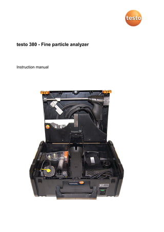
  • 1. testo 380 - Fine particle analyzer Instruction manual
  • 2. 2
  • 3. 1 Contents 3 1 Contents 1 Contents...................................................................................................3 2 Safety and the environment....................................................................6 2.1. About this document........................................................................6 2.2. Ensure safety...................................................................................7 2.3. Protecting the environment..............................................................9 3 Specifications ........................................................................................10 3.1. Use................................................................................................10 3.2. Technical data ...............................................................................10 3.2.1. Examinations and licenses ............................................................................10 3.2.2. Declaration of Conformity ..............................................................................12 3.2.3. Measuring range, accuracy and resolution.....................................................13 3.2.4. Instrument data..............................................................................................13 3.2.5. Other instrument data ....................................................................................14 3.2.6. Particulate matter probe.................................................................................14 3.2.7. Warranty........................................................................................................14 4 Product description...............................................................................15 4.1. Scope of delivery...........................................................................15 4.2. Overview of testo 380....................................................................16 4.3. Overview of particulate matter probe.............................................17 4.4. Overview of outlet nozzles in the testo 380 ...................................18 4.5. Overview of cleaning material........................................................19 4.6. Overview of status displays ...........................................................19 4.6.1. testo 380 status display .................................................................................19 4.6.2. Particulate matter probe status display ..........................................................20 4.6.3. Measurement system status display ..............................................................20 4.6.3.1. Status display of the testo 330-2 LL V2010 (item no. 0632 3307)....20 4.6.3.2. Status display of the testo 330-2 LL/F (item no. 0632 3305)............20 4.7. Gas path........................................................................................21 5 First steps ..............................................................................................24 5.1. Getting to know the product...........................................................24 5.1.1. Checking the firmware version of the testo 330 .............................................24 5.1.2. Inserting the testo 330 ...................................................................................25 5.1.3. Connecting the preheating section.................................................................26 5.1.4. Connecting the particulate matter probe ........................................................27 5.1.5. Using the particulate matter probe .................................................................29 5.1.6. Mains operation .............................................................................................30 5.1.7. Switching the measuring system on...............................................................30 5.1.8. Switching the measuring system off...............................................................30 5.1.9. Removing the testo 330 from the testo 380....................................................30
  • 4. 1 Contents 4 6 Using the product ................................................................................. 31 6.1. Particle reading display................................................................. 31 6.2. Conducting a measurement, testo 330-2 LL V2010 (0632 3307).. 32 6.2.1. Preparing for measurement ...........................................................................32 6.2.2. Particle: test types – compliance measurement, adjustment help and approval test..................................................................................................34 6.3. Conducting a measurement, testo 330-2 LL/F (0632 3305).......... 39 6.3.1. Preparing for measurement ...........................................................................39 6.3.2. Particle: test types – compliance measurement, adjustment help and approval test..................................................................................................40 6.4. Concluding measurement ............................................................. 46 6.5. Transferring data........................................................................... 49 6.5.1. Record printer................................................................................................49 6.5.2. PC/pocket PC................................................................................................49 6.5.3. Data transfer to IrDA record printer................................................................50 7 Maintaining the product ....................................................................... 51 7.1. Servicing interval........................................................................... 51 7.2. Cleaning the testo 380 and testo 330 ........................................... 51 7.3. Draining the condensate container ............................................... 51 7.4. Checking/replacing the crude gas fresh air filter and secondary filter.............................................................................. 54 7.5. Checking/replacing the crude gas primary filter ............................ 55 7.6. Checking/replacing the cotton filter............................................... 57 7.7. Cleaning the rotation and stator disc in the rotation diluter ........... 58 7.8. Cleaning the probe shaft of the particulate matter probe .............. 62 7.9. Cleaning/replacing the sensor module.......................................... 64 7.9.1. Removing the sensor module ........................................................................64 7.9.2. Cleaning the sensor module ..........................................................................66 7.9.3. Inserting a cleaned or new sensor module.....................................................66 7.10. Cleaning the nozzle ...................................................................... 67 7.10.1. Removing the nozzle .....................................................................................67 7.10.2. Cleaning the nozzle .......................................................................................68 7.10.3. Inserting the nozzle........................................................................................69 7.11. Replacing the nozzle..................................................................... 70 7.11.1. Using a used nozzle ......................................................................................70 7.11.2. Using a new nozzle........................................................................................71 7.12. Changing the crude gas and/or measurement gas tube ............... 72 7.13. Operation check............................................................................ 74
  • 5. 1 Contents 5 8 Tips and assistance...............................................................................75 8.1. Questions and answers .................................................................75 8.2. Accessories and spare parts .........................................................80 8.3. Updating instrument software for testo 330-2 LL V2010 (0632 3307) ...................................................................................82 8.4. Updating instrument software for testo 330-2 LL/F (0632 3305)....82 8.5. Updating instrument software for testo 380 ...................................82
  • 6. 2 Safety and the environment 6 2 Safety and the environment 2.1. About this document Use > Please read this documentation through carefully and familiarize yourself with the product before putting it to use. Pay particular attention to the safety instructions and warning advice in order to prevent injuries and damage to the products. > Keep this document to hand so that you can refer to it when necessary. > Hand this documentation on to any subsequent users of the product. Warnings Always pay attention to information that is marked by the following warnings with warning pictograms. Implement the specified precautionary measures. Representation Explanation CAUTION indicates potential minor injuries NOTICE indicates circumstances that may lead to damage to the products WARNING Indicates potential serious injuries
  • 7. 2 Safety and the environment 7 Symbols and writing standards Represen- tation Explanation Note: Basic or further information. 1. ... 2. ... Action: more steps, the sequence must be followed. > ... Action: a step or an optional step. - ... Result of an action. [OK] Control keys of the instrument or buttons of the program interface. 2.2. Ensure safety > Only operate the product properly, for its intended purpose and within the parameters specified in the technical data. Do not use any force. > The testo 380 must be checked for any visible damage before commissioning. Do not commission the testo 380 if there are any signs of damage on the housing, mains unit or supply lines. > Do not perform contact measurements on non-insulated, live parts. > Do not store the product together with solvents. Do not use any desiccants. > Carry out only the maintenance and repair work on this instrument that is described in the documentation. Follow the prescribed steps exactly. Use only original spare parts from Testo. > Any further or additional work must only be carried out by authorised personnel. Testo will otherwise refuse to accept responsibility for the proper functioning of the measuring instrument after repair and for the validity of certifications. > Only use the device in closed, dry rooms and protect it from rain and moisture. > Temperatures given on probes/sensors relate only to the measuring range of the sensors. Do not expose handles and feed lines to any temperatures in excess of 70 °C unless they are expressly permitted for higher temperatures.
  • 8. 2 Safety and the environment 8 > The objects to be measured or the measurement environment may also pose risks: Note the safety regulations valid in your area when performing the measurements. > The measurement system has been verified as a short-term measuring instrument and should not be used as a safety (alarm) instrument. > Supervise the measurement system during operation. > The measuring instrument can be operated in closed rooms. The maximum allowable concentration (MAC) value for CO of 30 ppm is attained by operating the measuring instrument under the following boundary conditions after approx. 4.5 h measuring time at the earliest (in cases where there is no air exchange): Room dimensions (L x W x H) 3 m x 3 m x 2 m Flue gas concentration 5000 ppm CO > Do not store or transport any fluids in the transport case. > Do not operate the instrument if there is condensation on the housing. WARNING There is water in the transport case. Risk of electric shock! > Do not operate the measurement system. > Check for fluids before each start-up. > Do not store or transport any conductive incidentals (without protective cover/container) in the transport case. > Do not use mains cable if there is any external damage to it and protect it from hot surfaces. > Secure measurement system during transport in order to prevent damage to the measurement system.
  • 9. 2 Safety and the environment 9 2.3. Protecting the environment Before disposing of the product, the condensate trap must be emptied and the condensate in the crude gas tube disposed of in a suitable container. > Dispose of faulty rechargeable batteries/spent batteries in accordance with the valid legal specifications. > At the end of its useful life, send the product to the separate collection for electric and electronic devices (observe local regulations) or return the product to Testo for disposal.
  • 10. 3 Specifications 10 3 Specifications 3.1. Use The testo 380 must be used in conjunction with testo 330-2 LL. The designation testo 330-2 LL includes the measuring instrument • testo 330-2 LL/F, item no. 0632 3305 or • testo 330-2 LL V2010, item no. 0632 3307. The order no. is located on the label on the rear of the housing. The testo 380 is a professional dust measuring instrument for determining particulate matter concentrations. The measuring instrument can be used to directly determine dust emissions in g/m3 on site from solid fuel systems. The instrument is suitable • for official measurements in accordance with the first German Federal Imission Control Ordinance (BImSchV) • as an adjustment aid for combustion processes • for the approval test of individual room furnaces. Changes in dust emissions, caused by a system's parameter settings for example, can be directly recorded via the online display. Thus the particulate matter analyzer testo 380, in conjunction with the testo 330-2 LL, constitutes a measurement system. 3.2. Technical data 3.2.1. Examinations and licenses As declared in the Certificate of Conformity, this product complies with Directive 2004/108/EC. This product is TÜV-tested in accordance with the provisions of VDI 4206-2. This product makes it possible to monitor limit value compliance for particles in accordance with level 1 and level 2 of the first German Federal Imission Control Ordinance (BImSchV). This product complies with the provisions of VDI 50379-2. The testo 380 and its components comply with the provisions of EN 61010-1. The testo 380 complies with the provisions of EN 50270 for instrument class 1.
  • 11. 3 Specifications 11 The testo 380 is approved for fuels in accordance with instrument class A, B and C of VDI 4206-2. This corresponds to fuel groups 1 - 8 in accordance with § 3 of the first German Federal Imission Control Ordinance (BImSchV): 1. Coal, non-pitch-bonded coal briquettes, coal coke 2. Lignite, lignite briquettes, lignite coke 3. Fuel peat, fuel peat pellets 3a. Barbecue charcoal, barbecue charcoal briquettes in accordance with DIN EN 1860, September 2005 edition 4. Natural chunky wood, including attached bark, especially in the form of split logs, chippings, brushwood or cones 5. Natural non-chunky wood, especially in the form of sawdust, shavings, abrasive dust or bark 5a. Pressed items made of natural wood in the form of wood briquettes in accordance with DIN 51731, October 1996 edition, or in the form of wood pellets in accordance with the fuel requirements of the DINplus Certification Program “Wood pellets for use in small furnaces in accordance with DIN 51731- HP 5”, August 2007 edition, and other wood briquettes or wood pellets made of natural wood with equal quality. 6. Painted, varnished or coated wood and any scrap materials from the same, insofar as no wood preservatives have been applied or are included due to treatment, and coatings do not contain any halogenated organic compounds or heavy metals. 7. Plywood, chipboard, fibreboard or otherwise glued wood and any scrap materials from the same, insofar as no wood preservatives have been applied or are included due to treatment, and coatings do not contain any halogenated organic compounds or heavy metals. 8. Straw and other plant materials, cereal which is not intended as food, such as rolled grain, cracked grain, whole grain plants, cereal debris, husk and remainders of cornstalk and pellets from the aforementioned fuels. For official measurements in accordance with the 1st BImSchV (chimney sweeps) and in accordance with VDI 4206 Part 2, the measuring instrument must be checked every six months by a technical testing body of the Guild of Master Chimney Sweeps or another testing body recognised by the authorities.
  • 13. 3 Specifications 13 3.2.3. Measuring range, accuracy and resolution Measuremen t parameter Measuring range Accuracy Resolution Particulate matter1 0 to 0.3 g/m3 According to VDI 4206-2 0.0001 g/m3 Flue gas temperature 0 to 500 °C According to VDI 4206-1 0.1 °C 3.2.4. Instrument data Feature Values Storage and transport temperature -20 to 50 °C Protection class 2 Operating temperature +5 to 40 °C Ambient humidity 0 to 90% RH, non-condensing Protection class IP40 Weight testo 380: 7.9 kg, testo 330: 0.65 kg Dimensions (L x W x H) 475 mm x 360 mm x 190 mm Housing material ABS Power supply via the internal mains unit: 100 V AC/2.1 A - 240 V AC/ 0.95 A (50-60 Hz) Power consumption max. 120 W Readiness for operation approx. 10 to 15 min 1 Measurements over 0.3 g/m 3 are possible, but are not part of the requirement outlined in VDI 4206-2.
  • 14. 3 Specifications 14 3.2.5. Other instrument data Feature Values Nozzle No wear and tear when used as intended 3.2.6. Particulate matter probe Feature Values Length 270 mm Integrated elements Draught path, sampling, temperature measurement, probe heater, rotation diluter Flue gas temperature max. 500 °C Probe shaft heating up to 120 °C Rotation diluter heated (up to 80 °C) Status display LED, displays warm-up phase and operational readiness Probe cable Length: 2.2 m Probe shaft Stainless steel 1,4301 Diameter of probe shaft 12 mm 3.2.7. Warranty Feature Values Warranty testo 380 with particulate matter probe: 24 months (excluding wear parts such as engines, pumps and filters) Sensor module: 12 months Terms of warranty see website www.testo.com/warranty
  • 15. 4 Product description 15 4 Product description 4.1. Scope of delivery • Particulate matter analyzer testo 380 (item no. 0632 3800) • Particulate matter probe • Preheating section • Cleaning material consists of: ◦ Cotton buds ◦ Syringe ◦ Hose attachment for the syringe ◦ Cleaning box for the nozzle ◦ Cover cap for the probe shaft ◦ Cover cap for the condensate trap • Fixing chain for the particulate matter probe • Cleaning brush for the probe shaft • Instruction manual • testo 380 mains cable The testo 380 is delivered in a specially designed shipping carton in order to prevent damage during transport. Testo recommends keeping the packaging unit and using it again if you need to return the product.
  • 16. 4 Product description 16 4.2. Overview of testo 380 1 Particulate matter sensor hose connection 2 Particulate matter sensor with preheating section and pressure tube 3 Combustion air temperature probe connection 4 USB connection for updating the testo 380 5 Cotton filters incl. crude gas primary filter 6 Cleaning materials storage compartment 7 Fresh air filter 8 Fresh air inlet 9 Crude gas secondary filter 10 Condensate container 11 Compartment for instruction manuals 12 Transport securing device
  • 17. 4 Product description 17 13 Particulate matter probe (probe is permanently assigned to the measurement system) 14 Magnetic holder for the printer 15 Holder for testo 330 and securing clip for case lid 16 Printer (accessory) 17 Storage compartment 18 Storage compartment for the mains cable 19 Mains connection and on/off switch 20 Probe connection 21 Status display 22 Storage compartments for containers 4.3. Overview of particulate matter probe 1 Probe cable 2 Probe basket 3 Cone 4 Heatable probe shaft 5 Probe handle 6 Rotation diluter 7 Rotation diluter cover 8 Eyelet for chain for fixing probe in place
  • 18. 4 Product description 18 9 Status display 10 Connecting plug to the testo 380 11 Crude gas tube to the cotton filter 12 Measurement gas tube to the particulate matter sensor 4.4. Overview of outlet nozzles in the testo 380 1 Test connection for the test bed (gradient check) of a technical testing body of the Guild of Master Chimney Sweeps or other testing body recognised by the authorities. The cover cap on the test connection should only be removed for the gradient check. Removal of the cover cap outside of a gradient check will cause the testo 380 to malfunction. 2 Air inlet nozzle 3 Measurement gas outlet nozzle To prevent incorrect measurement results, do not extend the measurement gas outlet nozzle and/or air inlet nozzle with a hose.
  • 19. 4 Product description 19 4.5. Overview of cleaning material 1 Cleaning brush for the probe shaft 2 Cotton buds 3 Syringe with hose attachment 4 Cleaning box for the nozzle 4.6. Overview of status displays The status display indicates the operating status of the testo 380, the particulate matter probe and the measurement system. 4.6.1. testo 380 status display Display Status Permanently green Testo 380 is operational Flashing green Warming-up phase or standby mode, settings can be configured on the testo 330 LL. Flashing yellow Initialisation phase, system is not operational, no settings can be configured on the testo 330 LL. Flashing red System error, testo 380 is not operational.
  • 20. 4 Product description 20 4.6.2. Particulate matter probe status display Display Status Permanently green Particulate matter probe is operational Flashing green Warming-up phase Flashing red Fault 4.6.3. Measurement system status display 4.6.3.1. Status display of the testo 330-2 LL V2010 (item no. 0632 3307) The measurement system status display is indicated on the testo 330 display. 1 Measurement system status display Display Status Permanently green The system is ready for measurement. Flashing green The system is functional (e.g. tightness test can be started), but not yet ready for a measurement. Flashing yellow Initialisation phase, system is not operational, no settings can be configured on the testo 330 LL. Flashing red System error, system is not operational. 4.6.3.2. Status display of the testo 330-2 LL/F (item no. 0632 3305) The message Communication with t380 is tested... is shown on the display.
  • 21. 4 Product description 21 4.7. Gas path Item / Designation Illustration 1 testo 330 2 Draught inlet 3 Adapter 4 Crude gas inlet
  • 22. 4 Product description 22 Item / Designation Illustration 5 Fresh air inlet 6 Fresh air filter 7 Condensate container 8 Primary filter 9 Cotton filter 10 Secondary filter 11 Particulate matter probe socket 12 Crude gas inlet 13 Draught inlet 14 Crude gas path probe shaft 15 Probe shaft 16 Crude gas tube 17 Measurement gas tube 18 Rotation diluter 19 Probe cable
  • 23. 4 Product description 23 Item / Designation Illustration 20 Preheating section 21 Particle sensor 22 Pressure tube 23 Measurement gas outlet nozzle 24 Test connection for the test bed
  • 24. 5 First steps 24 5 First steps 5.1. Getting to know the product Please refer to the testo 330 instruction manual for information relating to commissioning and operation of the testo 330. 5.1.1. Checking the firmware version of the testo 330 In order to control the testo 380, the testo 330 used must have the following firmware version: • 0632 3305 firmware version V 2.0 onwards • 0632 3307 firmware version V 2.0 onwards The firmware version status of the testo 330 can be called up in the Device information menu or via the [ i ] key. Switch on the testo 330: > Press [ ]. testo 330-2 LL V2010 (0632 3307) Call up function: > [ ] → Instrument diagnosis → Device information → [OK]. or > [ i ] → Device information → [OK]. To download the current instrument software (firmware) for the testo 330- 2 LL V2010 (0632 3307), see Updating instrument software for testo 330-2 LL V2010 (0632 3307), page 82. testo 330-2 LL/F (0632 3305) Call up function: > [ ] → Instrument diagnosis → [OK]. or > [ i ] → Instrument diagnosis → [OK]. To download the current instrument software (firmware) for the testo 330-2 LL/F (0632 3305), see Updating instrument software for testo 330-2 LL/F (0632 3305), page 82.
  • 25. 5 First steps 25 5.1.2. Inserting the testo 330 There is no need to switch off the testo 330 to insert it into the testo 380. 1. Fold up securing clip and click into place on the case lid. 2. Lift up the repository for the testo 330 and insert the measuring instrument.
  • 26. 5 First steps 26 3. Insert the testo 330 into the holder and fix in place using the locking lever. 5.1.3. Connecting the preheating section 1. Remove the cover of the particulate matter sensor. 2. Put preheating section onto the particulate matter sensor and lock by turning (clockwise).
  • 27. 5 First steps 27 5.1.4. Connecting the particulate matter probe 1 1 Transport securing device 2 Rubber ring Always connect the particulate matter probe prior to switching on the testo 380. The particulate matter probe is detected during the testo 380 activation process. The particulate matter probe will not be detected by the testo 380 if it is not connected until after the testo 380 has been switched on or if it is disconnected from the testo 380 during a measurement. The particulate matter probe will only be detected once the testo 380 has been switched on again. 1. Open the transport securing device (1) and rubber ring (2). 2. Take the particulate matter probe cable out of the storage compartment.
  • 28. 5 First steps 28 3. Connect up the particulate matter probe connections - to the particulate matter sensor with preheating section (1) - to the condensate container cotton filter (2) - to the probe socket for the testo 380 (3). CAUTION Hot probe shaft due to automatic heat-up! Risk of burns! > Do not touch the probe shaft. 4. Take the particulate matter probe out of the holder.
  • 29. 5 First steps 29 5.1.5. Using the particulate matter probe CAUTION Hot probe shaft due to automatic heat-up! Risk of burns! > Do not touch the probe shaft. ATTENTION Backflow of condensate from the crude gas tube! Clogging of the rotation discs and damage to the testo 380. > Before removing the particulate matter probe from the flue gas duct, remove the crude gas tube from the particulate matter probe connection and dispose of the condensate in a suitable container. Checking the thermocouple The thermocouple of the particulate matter probe must not lie against the probe cage. > Check before use. Bend the thermocouple back if necessary. Aligning the particulate matter probe > Turn the particulate matter probe to align the thermocouple so that it is freely exposed to the flue gas flow. > Align the particulate matter probe in the flue gas duct so that the tip of the particulate matter probe is in the centre of flow (area of the highest flue gas temperature).
  • 30. 5 First steps 30 5.1.6. Mains operation > Connect the mains cable to the mains connection of the testo 380 and a mains socket with earthing contact. - Power to the testo 330 is supplied via the testo 380. - The rechargeable battery of the testo 330 is not charged while operated in conjunction with the testo 380. CAUTION Operation of the measurement system when the cover is closed Superheating of the measurement system! > Only conduct measurements when the cover is open. 5.1.7. Switching the measuring system on 1. Check that all system components are properly connected. 2. Switch on the measurement system: [ ] - The start screen is displayed (duration: about 15 s). - If the voltage supply was interrupted for a longer period: The menu Date / Time is opened. - The gas sensors are set to zero. - If there is an instrument error, the Error diagnosis menu is displayed. - The Measurement options menu is displayed 5.1.8. Switching the measuring system off 1. Switch off the testo 330: Press [ ]. - As may be the case: the pump starts and the sensors are rinsed until the switch-off thresholds (O2 > 20 %, other measurement parameters < 50 ppm) are reached. The maximum rinsing period is 3 minutes. - The measuring instrument switches off. 2. Switch off the testo 380: [ ] 5.1.9. Removing the testo 330 from the testo 380 1. Release the locking lever. 2. Remove the testo 330. 3. Release securing clip on the case lid and fold down.
  • 31. 6 Using the product 31 6 Using the product 6.1. Particle reading display The measurement parameters for the Particle measurement type are predefined and cannot be adjusted. Overview of measurement parameters: Display Measurement parameter g/m 3 PMØ Mean value of the particulate mass since the start of the measurement g/m 3 PMØu Averaged end result dust less measurement uncertainty (only displayed at the end of a measurement). g/m 3 COØu Averaged end result CO less measurement uncertainty (the result is only displayed at the end of a measurement). % O2 Oxygen concentration ppm CO Carbon monoxide concentration mg/m 3 CO Carbon monoxide concentration °C FT Flue gas temperature °C AT Combustion air temperature (measurement only possible and permitted with external temperature probe 0600 9787). % FH Flue gas humidity (calculated) The mean value display of the following readings can also be set: % O2, ppm CO, mg/m3 CO, °C FT, °C AT, % qA, % FH, mbar draught
  • 32. 6 Using the product 32 6.2. Conducting a measurement, testo 330-2 LL V2010 (0632 3307) 6.2.1. Preparing for measurement The time required for an official measurement is approx. 30 min. If you switch to wood chips as fuel immediately following a measurement using wood pellets or split logs as fuel, the message Particulate matter sensor and sensor cover need to cool down (this process may take a few minutes) appears. Testo recommends opening the particulate matter sensor cover prior to selecting wood chips as fuel, so that the sensor can cool down, see Cleaning/replacing the sensor module, page 64. To shorten the cooling down period, the sensor should be moved to a cold environment or placed on a cold surface. Overview of the fuels to be selected (based on VDI 4206 Sheet 2: 2011-06) Instru ment class Fuel group acc. to § 3 of the 1st BImSchV Form of fuel / fuel type Fuel to be selected with testo 380 A 4 4, 5 5a Split logs with attached bark Wood chips Pellets or briquettes in accordance with DIN 51731 Split logs Wood chips Pellets B 6, 7 8 8 Laminated wood- based products (N content > 4.0 %) Straw and straw pellets Cereal grains Chipboard Straw Cereals C 1, 2, 3 Lignite briquettes Anthracite Lignite Anthracite
  • 33. 6 Using the product 33 The First steps chapter must have been read. CAUTION Preventing measurement errors > Do not place or operate the measurement system on heat sources, e.g. boilers. Tightness test For an official measurement, the tightness of the measurement system must be checked prior to every measurement. The locking lever for fixing the testo 330 in place must be closed. Call up function: > [ ] → Measurement options → [OK] → Particle → [OK] → [Options] → Tightness test → [OK]. 1. Take the cover caps for the condensate trap and for the particulate matter probe out of the enclosed plastic bag. 2. Place cover cap (1) on the fresh air inlet of the condensate container. 3. Place cover cap (2) on the probe shaft of the particulate matter probe. - The tightness of the crude gas and measurement gas path is indicated by a traffic light. - If leaks in the crude gas path and/or the measurement gas path were exposed during the tightness test, see Questions and answers, page 75.
  • 34. 6 Using the product 34 4. Once the tightness test has been successfully conducted (both traffic lights on green), remove the cover caps from the fresh air inlet and probe shaft. 5. Finish the tightness test: [Close]. 6. Put the cover caps back in the plastic bag. 6.2.2. Particle: test types – compliance measurement, adjustment help and approval test To prevent incorrect measurements, the position of the testo 380 and the particulate matter probe must not be changed during a measurement. For flue gas loss measurement, Testo recommends using a combustion air temperature probe with connecting cable (0600 9787). Self-heating of the measurement system during operation may influence the combustion air temperature measurement with a mini ambient air probe. Call up function: > [ ] → Measurement options → [OK] → Particle → [OK]. The testo 380 has 3 test types: • the Compliance measurement test is for official measurements in accordance with the 1st BImSchV • the Adjustment help test is for the adjustment of combustion processes • Approval test is for individual room furnaces > The operating status of the combustion system to be measured must comply with the national directives. Options > [Options] → Tightness test: the tightness of the fresh air and gas path is tested. > [Options] → Operation check: an operation check of the measurement system can be carried out, see Operation check, page 74. > [Options] → Instrument information particle probe: information on the particulate matter probe is displayed. > [Options] → Instrument information particle analyzer: testo 380 information is displayed. > [Options] → Edit cone data: select and edit nozzle calibration data.
  • 35. 6 Using the product 35 > [Options] → Recalibrate: (this function is not available during a measurement): The gas sensors are set to zero. > [Options] → Address/Location: (this function is not available during a measurement): the Address/Location folder is opened. > [Options] → Particle sensor pump: on/off: the sensor pump is switched on or off. > [Options] → Test Bed (gradient check) (only for test beds and Testo Service): procedure for checking the determinant measurement parameters for the six-monthly inspection of the test bed with specialised equipment. > [Options] → Diagnosis (service): only for Testo Service. Measuring 1. Select compliance measurement, adjustment help or approval test: [▼] → [OK]. 2. Select solid fuel: [▲], [▼] → [OK]. 3. Select parameter: [▲], [▼] → [Edit] . Fuel humidity (±15 %u), ambient temperature (±3 °C amb. temp.) and ambient humidity (± 15 %RH amb. humidity) influence the measurement result. The values specified are factory settings and need to be adapted to the existing conditions. At a measuring location, the ambient temperature and humidity should always be determined from the same location. Testo recommends the testo 606-2 wood moisture measuring instrument for determining the above parameters (item no. 0560 6062-2). When the parameter Part load is selected, a signal is sounded after 5 min when a measurement is conducted. The signal is very helpful for measurements in the partial load range as per § 25 para 2 of the 1st BImSchV. If the measurement system is exposed to ambient temperatures that are outside the operating temperature range specified in the technical data, a longer stability time can be expected. The temperature of the measurement system should not differ significantly from the ambient temperature at the measuring location. If this is the case, allow the measurement system to adjust to the ambient temperature prior to operation.
  • 36. 6 Using the product 36 4. Enter values: [▲], [▼] and sometimes [◄], [►] → [OK]. - Particulate matter probe is preheated to 50 °C (status display flashes green). - Measurement system is operational (status display lights up green). 5. [Next] Adjustment help measurement: continue with point 9 Compliance measurement: continue with point 6 Approval test: continue with point 6 6. Start draught measurement: [ ]. - Draught zeroing. 7. Position the particulate matter probe in the centre of flow (area of the highest flue gas temperature). The display showing the maximum measured flue gas temperature (FT max) helps when positioning the probe. - The reading is displayed. 8. End draught measurement: [ ] 9. [Next] If the message Stability not yet achieved. Please wait… appears, do not start any measurement until the message is no longer displayed.
  • 37. 6 Using the product 37 10. Start measurement: [ ]. - The stability time (approx. 3 min) elapses. Following this, the measuring phase begins automatically. The measuring phase can be interrupted early: > press [Cancel] . - The measurement result is displayed once the measuring phase has been completed 11. Prepare the instrument for rinsing. > Remove particulate matter probe from the flue gas duct → [OK]. - Rinsing starts 12. Clean the sensor module, see Cleaning/replacing the sensor module, page 64. 13. [OK]. > A test report can be printed out if necessary. Data is printed out via the [ ] key or the Options menu. Only readings assigned a display field in the measurement view will be saved / printed out. Measurement data can be printed out during a measurement. To be able to transfer data to a record printer via infrared or Bluetooth interface, the printer used must be enabled.
  • 38. 6 Using the product 38 Printout of a test report2, 3 14. End measurement: [Close]. Options: > [Options] → Show Graphic: the readings are displayed in the form of a line graph. 2 KI:= confidence interval The measurement uncertainty indicates the possible dispersion around the reading established (as accurately as possible). The associated probability is characterised by the confidence interval. The 95% confidence interval specifies the range around the reading within which the "true value" is presumed to be with 95% probability. 3 The system type can be changed via Address/Location (Air Heater / Combination Boiler).
  • 39. 6 Using the product 39 > [Options] → Configure Graphic: the measurement parameters to be represented (max. 4) can be displayed ( ) or hidden ( ). > [Options] → Mean: the mean values of a measurement are displayed. > [Options] → Number of lines: change the number of readings shown per display page. > [Options] → repeat: in the case of the compliance measurement and approval test, the measurement can be restarted several times within the first 2 minutes if necessary. 6.3. Conducting a measurement, testo 330-2 LL/F (0632 3305) 6.3.1. Preparing for measurement The time required for an official measurement is approx. 30 min. If you switch to wood chips as fuel immediately following a measurement using wood pellets or split logs as fuel, the message Particulate matter sensor and sensor cover need to cool down (this process may take a few minutes) appears. Prior to selecting wood chips as fuel, Testo recommends opening the particulate matter sensor cover so that the sensor can cool down, . To shorten the cooling down period, the sensor should be moved to a cold environment or placed on a cold surface. The First steps chapter must have been read. CAUTION Preventing measurement errors > Do not place or operate the measurement system on heat sources, e.g. boilers. Tightness test For an official measurement, the tightness of the measurement system must be checked prior to every measurement. The locking lever for fixing the testo 330 in place must be closed. Call up function: > [ ] → Measurement options → [OK] → Particle → [OK] → Tightness test → [OK].
  • 40. 6 Using the product 40 1. Place cover cap (1) on the fresh air inlet of the condensate container. 2. Place cover cap (2) on the probe shaft of the particulate matter probe. - The tightness of the crude gas and measurement gas path is displayed (crude gas path value < 0.02 l/min, measurement gas path value <0.4 mbar). - If leaks in the crude gas path and/or the measurement gas path were exposed during the tightness test, see Questions and answers, page 75. 3. Once the tightness test has been successfully conducted, remove the cover caps from the fresh air inlet and probe shaft: [OK]. 4. Finish the tightness test: [Finished]. 6.3.2. Particle: test types – compliance measurement, adjustment help and approval test To prevent incorrect measurements, the position of the testo 380 and the particulate matter probe must not be changed during a measurement. For flue gas loss measurement, Testo recommends using a combustion air temperature probe with connecting cable. Self-heating of the measurement system during operation may influence the combustion air temperature measurement with a mini ambient air probe. Call up function: > [ ] → Measurement options → [OK] → Particle → [OK].
  • 41. 6 Using the product 41 The testo 380 has 3 test types: • the Compliance measurement test is for official measurements in accordance with the 1st BImSchV • the Adjustment help test is for the adjustment of combustion processes • Approval test is for individual room furnaces > The operating status of the combustion system to be measured must comply with the national directives. Options > Operation check: an operation check of the measurement system can be carried out, . > Tightness test: the tightness of the fresh air and gas path is tested. > Particle analyzer info: testo 380 information is displayed. > Probe info: information on the particulate matter probe is displayed. > Nozzle data: select and edit nozzle calibration data. > Particle sensor pump: on or Particle sensor pump: off: the sensor pump is switched on or off. > [Options] → Test Bed (gradient check) (only for test beds and testo Service): procedure for checking the determinant measurement parameters for the six-monthly inspection of the test bed with specialised equipment. > [Options] → Diagnosis (service): only for Testo Service. Measuring 1. Select compliance measurement, adjustment help or approval test: [▼] → [OK]. - System check: tightness test successfully completed? > [Yes]: continue with point 2. > [No]: Carry out tightness test. 2. Select solid fuel: [▲], [▼] → [OK].
  • 42. 6 Using the product 42 3. Select parameter: [▲], [▼] → [Edit]. Fuel humidity (±15 %u), ambient temperature (±3 °C amb. temp.) and ambient humidity (± 15 %RH amb. humidity) influence the measurement result. The values specified are factory settings and need to be adapted to the existing conditions. At a measuring location, the ambient temperature and humidity should always be determined from the same location. Testo recommends the testo 606-2 wood moisture measuring instrument for determining the above parameters (item no. 0560 6062-2). When the parameter Part load is selected, a signal is sounded after 5 min when a measurement is conducted. The signal is very helpful for measurements in the partial load range as per § 25 para 2 of the 1st BImSchV. If the measurement system is exposed to ambient temperatures that are outside the operating temperature range specified in the technical data, a longer stability time can be expected. The temperature of the measurement system should not differ significantly from the ambient temperature at the measuring location. If this is the case, allow the measurement system to adjust to the ambient temperature prior to operation.
  • 43. 6 Using the product 43 4. Enter values: [▲], [▼] and sometimes [◄], [►] → [OK]. - Particulate matter probe is preheated to 50 °C (status display flashes green). - Measurement system is operational (status display lights up green). 5. [Next] Adjustment help measurement: continue with point 9 Compliance measurement: continue with point 6 Approval test: continue with point 6 6. Start draught measurement: [Start]. - Draught zeroing. 7. Position the particulate matter probe in the centre of flow (area of the highest flue gas temperature). The display showing the maximum measured flue gas temperature (FT max) helps when positioning the probe. - The reading is displayed. 8. End draught measurement: [Stop] 9. [Next] If the message Stability not yet achieved. Please wait… appears, do not start any measurement until the message is no longer displayed. 10. Start measurement: [Start ]. - The stability time (approx. 3 min) elapses. Following this, the measuring phase begins automatically. The measuring phase can be interrupted early: > press [Canc.]. Options > Mean: the mean values of a measurement are displayed. > New: The measurement is restarted. - The measurement result is displayed once the measuring phase has been completed 11. Prepare the instrument for rinsing. > Remove particulate matter probe from the flue gas duct → [OK]. - Rinsing starts 12. Clean the sensor module, .
  • 44. 6 Using the product 44 13. [Finished]. > A test report can be printed out if necessary. Data is printed out via the [Print] key. Only readings assigned a display field in the measurement view will be saved / printed out. Measurement data can be printed out during a measurement. To be able to transfer data to a record printer via infrared or Bluetooth interface, the printer used must be enabled.
  • 45. 6 Using the product 45 Printout of a test report 4,5 14. End measurement: [Finished]. 4 KI:= confidence interval The measurement uncertainty indicates the possible dispersion around the reading established (as accurately as possible). The associated probability is characterised by the confidence interval. The 95% confidence interval specifies the range around the reading within which the "true value" is presumed to be with 95% probability. 5 The system type can be changed via Address/Location (Air Heater / Combination Boiler).
  • 46. 6 Using the product 46 6.4. Concluding measurement 1. Switch off the testo 330: Press [ ]. 2. Switch off the testo 380: [ ]. 3. Remove crude gas tube from the particulate matter probe connection. ATTENTION Backflow of condensate from the crude gas tube! Clogging of the rotation discs and damage to the testo 380. > Before removing the particulate matter probe from the flue gas duct, remove the crude gas tube from the particulate matter probe connection and dispose of the condensate in a suitable container. CAUTION Hot probe shaft! Risk of burns! > Allow the probe shaft to cool down before you touch or pack it! 4. Remove the particulate matter probe connections - to the probe socket - to the particulate matter sensor with preheating section - to the cotton filter.
  • 47. 6 Using the product 47 5. Put probe cable into the storage compartment. 6. Insert the particulate matter probe into the holder and secure with the rubber ring.
  • 48. 6 Using the product 48 7. Wind up probe cable and stow away in the storage compartment. To prevent damage to the case lid, ensure that the probe cable is stowed away correctly in the storage compartment and that the case lid closes easily.
  • 49. 6 Using the product 49 8. Lock the transport securing device. 9. Release the preheating section from the particulate matter sensor by turning it (anti-clockwise) and remove. 10. If necessary remove the testo 330, release the securing clip, then close the transport case. 6.5. Transferring data 6.5.1. Record printer In order to be able to transfer data to a testo record printer via the infrared or Bluetooth interface (optional), the printer used must be enabled, see testo 330 instruction manual. 6.5.2. PC/pocket PC Data can be transferred to a PC via USB, IrDA or Bluetooth ® . You must also refer to the documentation that comes with the software.
  • 50. 6 Using the product 50 6.5.3. Data transfer to IrDA record printer To transfer data from the measurement system to the IrDA record printer, the printer is attached to the magnetic plate (on the top of the testo 330).
  • 51. 7 Maintaining the product 51 7 Maintaining the product 7.1. Servicing interval Testo recommends having the measurement system checked once a year by Testo Service. 7.2. Cleaning the testo 380 and testo 330 > In order to prevent damage to the measurement system, the measurement system must be disconnected from the mains when being serviced and cleaned. > If the housing of the testo 380 and the testo 330 is dirty, clean it with a damp cloth. Do not use any aggressive cleaning agents or solvents! Mild household cleaning agents and soap suds may be used. > Clean ventilation slots, gas outlets, fresh air inlet and dilution air inlet with a vacuum cleaner. Do not blow out with compressed air. 7.3. Draining the condensate container The condensate consists of a weak mix of acids. Avoid skin contact. Make sure that the condensate does not run over the housing.
  • 52. 7 Maintaining the product 52 1. Remove the tube from the cotton filter connector, undo the cotton filter retaining clip and unlock the condensate container by the orange handle. 2. Remove condensate container horizontally from the testo 380. 3. Unscrew the cotton filter (anti-clockwise) and remove. 4. Clean out all condensate and dab off any remaining drops with a cloth.
  • 53. 7 Maintaining the product 53 5. Insert cotton filter and close (clockwise). 6. Insert the condensate container into the testo 380 and click into place. Push the tube onto the connector.
  • 54. 7 Maintaining the product 54 7.4. Checking/replacing the crude gas fresh air filter and secondary filter Checking the fresh air and secondary filters: > Check the fresh air and secondary filters regularly for contamination. In the event of visible contamination: change the filter. Replacing the fresh air and secondary filters: The filter chamber may contain condensate. When replacing the fresh air or the secondary filter, the condensate container must not be removed from the testo 380. 1. Open the filter chamber: turn the filter cover anti-clockwise and take it off. 2. Remove the exhausted filter and replace it with a new one.
  • 55. 7 Maintaining the product 55 3. Attach the filter cover and lock by turning it clockwise. The cross strut of the filter cover must be parallel to the orange handle of the condensate container. 7.5. Checking/replacing the crude gas primary filter Checking the primary filter: > Check the primary filter regularly for contamination. In the event of visible contamination: change the filter. Replacing the primary filter: The filter chamber may contain condensate. 1. Remove crude gas tube from the cotton filter connector, unlock the condensate container by the orange handle and the cotton filter. 2. Remove condensate container horizontally from the testo 380. 3. Unscrew the cotton filter (anti-clockwise) and remove. 4. Remove the primary filter from the cotton filter.
  • 56. 7 Maintaining the product 56 5. Open the primary filter housing. 6. Remove the exhausted filter and replace it with a new one. 7. Close the primary filter housing, place back on the cotton filter and press into position. Pay attention to the notch on the primary filter. 8. Insert cotton filter into the condensate container and close (clockwise). 9. Insert the condensate container into the testo 380 and click into place. Push the tube onto the connector.
  • 57. 7 Maintaining the product 57 7.6. Checking/replacing the cotton filter Checking the cotton filter > If contamination of the cotton filter is clearly visible (up to a half), the cotton wool must be replaced. Use only 100% cotton wool as a filter material. Replacing the cotton wool 1. Remove crude gas tube from the cotton filter connector, unlock the condensate container by the orange handle and the cotton filter. The condensate consists of a weak mix of acids. Avoid skin contact. Make sure that the condensate does not run over the housing. 2. Remove condensate container horizontally from the testo 380 and drain if necessary. 3. Unscrew the cotton filter (anti-clockwise) and remove. 4. Remove the primary filter from the cotton filter. 5. Remove the connector from the filter chamber. 6. Remove the cotton from the filter chamber. 7. Clean the filter chamber with a cloth.
  • 58. 7 Maintaining the product 58 8. Insert connector into the filter chamber. 9. Fill the filter chamber evenly with 5 g new cotton wool. Do not compress cotton wool unnecessarily. 10. Place the primary filter back on the cotton filter and press into position. Pay attention to the notch on the primary filter. 11. Insert cotton filter into the condensate container and close (clockwise). 12. Insert the condensate container into the testo 380 and click into place. Push the tube onto the connector. 7.7. Cleaning the rotation and stator disc in the rotation diluter If is advisable to clean the rotation diluter after every measurement. The rotation diluter is aligned with the measurement system. > In order to prevent incorrect measurements, rotation discs must not be exchanged between measurement systems. 1. Take the particulate matter probe out of the holder in the transport case. 2. Open the rotation diluter cover (turn anti-clockwise).
  • 59. 7 Maintaining the product 59 CAUTION Hot rotation and stator discs! Risk of burns! > Let rotation and stator discs cool down before touching them! 3. Depress the lock and pressure element and remove the lock. Then remove the pressure element via the shaft. 4. Remove the rotation disc via the shaft. After cleaning, make sure that the sealing surfaces of the rotation and stator disc are free of dust and are not scratched. Scratched sealing surfaces lead to incorrect measurement results and must be replaced by Testo Service.
  • 60. 7 Maintaining the product 60 Use distilled water to clean the rotation and stator disc. 5. Clean the rotation disc using a moistened cotton bud on the running surface and in the cavities and rub dry with an unused cotton bud. 6. Clean the stator disc using a moistened cotton bud and rub dry with an unused cotton bud.
  • 61. 7 Maintaining the product 61 7. Replace the rotation disc (pay attention to the locking pin on the particulate matter probe and the protrusion on the rotation disc). 8. Reinsert the pressure element and lock.
  • 62. 7 Maintaining the product 62 9. Close the rotation diluter cover (turn clockwise). 10. Insert the particulate matter probe into the holder and secure with the rubber ring. 7.8. Cleaning the probe shaft of the particulate matter probe In the event of any visible contamination, the probe shaft must be cleaned. CAUTION Hot probe shaft! Risk of burns! > Allow the probe shaft to cool down before you touch or pack it! 1. Take the particulate matter probe out of the holder in the transport case. 2. Open the rotation diluter cover (turn anti-clockwise).
  • 63. 7 Maintaining the product 63 3. Depress the lock and pressure element and remove. 4. Remove the rotation disc. 5. Insert the brushless side of the cleaning brush into the gas path 6. Push the cleaning brush through to the probe shaft tip. 7. Pull the cleaning brush out of the probe shaft. Repeat steps 5 and 6 several times depending on the degree of contamination. 8. Replace the rotation disc (pay attention to the locking pin on the probe and the protrusion on the rotation disc). 9. Reinsert the pressure element and lock. 10. Close the rotation diluter cover (turn clockwise). 11. Insert the particulate matter probe into the holder and secure with the rubber ring. 12. Lock the transport securing device.
  • 64. 7 Maintaining the product 64 7.9. Cleaning/replacing the sensor module 7.9.1. Removing the sensor module The sensor module must be cleaned after every measurement. 1. Remove the measurement gas tube from the preheating section. 2. Unlock the preheating section (anti-clockwise) and remove. 3. Remove the tube from the particulate matter sensor cover. 4. Unscrew the particulate matter sensor cover (anti-clockwise) and remove.
  • 65. 7 Maintaining the product 65 5. If the sensor module is located in the lower section of the particulate matter probe, remove the sensor module. or If the sensor module is located in the particulate matter sensor cover, proceed with the following steps: 6. Turn the particulate matter sensor cover over. 7. Tap lightly on the sensor module with your index finger. - Remove the sensor module from the particulate matter sensor cover.
  • 66. 7 Maintaining the product 66 7.9.2. Cleaning the sensor module 1 Sensor module 2 Runner 3 Sensor contacts 1. Carefully wipe the sensor module (1) and runner (2) with a dry cotton bud, applying only slight pressure. Do not touch the sensor contacts (3). If particles of dirt cannot be removed, the sensor module can be cleaned using a cotton bud moistened with distilled water. Particle residues may be visible in the form of a ring in the centre of the sensor module or a change of colour. It is not necessary to remove the remaining particle residues by increased pressure on the sensor module (risk of damage!), as the measurement system is recalibrated prior to every measurement. > Wipe between the sensor contacts, from one to another (3). 2. Rub the sensor module dry with an unused cotton bud. 7.9.3. Inserting a cleaned or new sensor module 1. Insert sensor module (observe markings) 2. Put the top part of the particulate matter sensor on and tighten (clockwise). 3. Attach the tube to the top part of the particulate matter sensor. 4. Attach the preheating section and lock (clockwise). 5. Attach the measurement gas tube.
  • 67. 7 Maintaining the product 67 7.10. Cleaning the nozzle - Necessary cleaning of the nozzle is indicated. 7.10.1. Removing the nozzle 1. Remove the measurement gas tube from the preheating section. 2. Unlock the preheating section (anti-clockwise) and remove. 3. Remove the tube from the top part of the particulate matter sensor. 4. Unscrew the top part of the particulate matter sensor (anti- clockwise) and remove. 5. Place the top part on a lint-free cloth on a flat surface. 6. Push down on the orange markings with a suitable tool and remove the cover. 7. Carefully remove the nozzle from the nozzle pot. Avoid touching the nozzle area.
  • 68. 7 Maintaining the product 68 7.10.2. Cleaning the nozzle > Fill the syringe with approx. 4 ml clean or distilled water and provide cleaning container. 1. Carefully remove more substantial surface contamination on the front and back with a moistened cotton bud. 2. Place nozzle at the opening of the cleaning container. 3. Push rubber hose onto the syringe. 4. Place the syringe with hose onto the nozzle so that no water escapes from the sealing surface.
  • 69. 7 Maintaining the product 69 5. Use constant pressure to push the water through the nozzle holes, so that two equally powerful jets of water are visible. 6. Remove the nozzle from the opening of the cleaning container and clean the areas on front and back with a lint-free cloth. 7. Rub nozzle dry using a lint-free cloth. Make absolutely sure that there are no residues on the nozzle after cleaning. 7.10.3. Inserting the nozzle 1. Carefully insert nozzle into the nozzle pot (the side with the inscription facing downwards). 2. Put cover and nozzle pot together and click into place.
  • 70. 7 Maintaining the product 70 3. Move snap coupling backwards and forwards several times. 4. Put the top part of the particulate matter sensor on the sensor module and tighten (clockwise). 5. Attach the tube to the top part of the particulate matter sensor. 6. Attach the preheating section and lock (clockwise). 7. Attach the measurement gas tube. 7.11. Replacing the nozzle 1. Remove the nozzle, see Removing the nozzle, page 67. > Place the nozzle into a protective container. 2. Insert nozzle, see Inserting the nozzle , page 69. 7.11.1. Using a used nozzle Use only cleaned nozzles. Select the nozzle calibration data. testo 330-2 LL V2010 (0632 3307) Call up function: > [ ] → Measurement options → [OK] → Particle → [OK] → [Options] → Edit cone data → [OK].
  • 71. 7 Maintaining the product 71 testo 330-2 LL/F (0632 3305) > [ ] → Measurement options → [OK] → Particle → [OK] → Nozzle data → [OK]. Select nozzle: > Select the line: [▲], [▼] The 8 numbers on the nozzle or the first 8 numbers on the package leaflet are of assistance when selecting the nozzle. > Save selection: [OK] - The selected nozzle is activated. 7.11.2. Using a new nozzle Enter the calibration data for the new nozzle. testo 330-2 LL V2010 (0632 3307) Call up function: > [ ] → Measurement options → [OK] → Particle → [OK] → [Options] → Edit cone data → [OK]. testo 330-2 LL/F (0632 3305) Call up function: > [ ] → Measurement options → [OK] → Particle → [OK] → Nozzle data → [OK]. Enter the nozzle data: > Select the line: [▲], [▼] → [Edit]. > When commissioning a new nozzle, enter the 13-digit code on the package leaflet.
  • 72. 7 Maintaining the product 72 1 Serial number 2 Sensor-specific data. The serial number (1) must be entered in reverse order from right to left. The sensor-specific data (2) is entered from left to right. > Enter values: [Edit] → [▲], [▼] and [◄], [►] → [OK]. > [Finished] for testo330-2 LL V2010 (0632 3307), [OK] for testo330-2 LL/F (0632 3305). 7.12. Changing the crude gas and/or measurement gas tube 1. Remove crude gas and/or measurement gas tube from the relevant particulate matter probe connection. 1. Open sealing clip and remove from the protective cover. 2. Take out the crude gas and/or measurement gas tube.
  • 73. 7 Maintaining the product 73 3. Insert new crude gas and/or measurement gas tube. Please ensure that the hose is inserted into the protective cover correctly. Connect crude gas and/or measurement gas tube to the particulate matter probe. 4. Insert crude gas and/or measurement gas tube each into one half of the sealing clip and carefully push the halves together (audible click).
  • 74. 7 Maintaining the product 74 7.13. Operation check The operation check is conducted to check the measurement system with respect to the determinant measurement parameters according to VDI 4206-2 via the test beds. This operation check can also be conducted by the operator outside of the regular checks, as required. The operation check takes approx. 40 min and is split into 3 sections: • Achieving system stability (approx. 10 min) • Determining the transport uncertainty (15 min) • Zero-point calibration (15 min) testo 330-2 LL V2010 (0632 3307) Call up function: > [ ] → Measurement options → [OK] → Particle → [OK] → [Options] → Operation check → [OK]. testo 330-2 LL/F (0632 3305) Call up function: > [ ] → Measurement options → [OK] → Particle → [OK] → Operation check → [OK]. 1. The measurement system stability check is carried out. 2. Start measurement: [ ]. - Diluter speed The rotation diluter's revolutions per minute over 15 minutes are displayed (while determining the transport uncertainty). - Transport uncertainty Over 15 minutes the cavities transported are counted and compared to the setpoint value (setpoint = number of rotation diluter cavities x number of rotations per minute x test duration). In the event of a deviation of less than +/- 15 cavities, the measurement system is fully functional. - Zero-point calibration Once the transport uncertainty has been determined, the zero point of the sensor is stored and monitored over the next 15 minutes. In the event of a deviation of max. +/- 1.5 Hz, the measurement system is fully functional. - The operation check is assessed automatically by the measurement system. 3. End operation check: [Close].
  • 75. 8 Tips and assistance 75 8 Tips and assistance 8.1. Questions and answers Error messages Error message Possible causes / solution Particulate matter sensor pressure incorrect! Check pressure tube. Cover of the particulate matter sensor is loose. Please check. > Check cover. Seal ring in the cover of the particulate matter sensor is damaged, dirty or not inserted. > Check seal ring. Sealing surface of the nozzle is dirty. > Check sealing surface. Air inlet nozzle and/or measurement gas outlet nozzle is blocked, e.g. by attached sealing cap. > Remove sealing cap. Kink in the pressure tube > Remove the kink in the pressure tube. Pressure sensor defective. > Contact Testo Service. Nozzle data incorrect. Please enter again. See instruction manual. Nozzle data has not been entered correctly. > Enter nozzle data again. Nozzle flow unstable. See instruction manual. (Error occurs during measurement). Nozzle is dirty. > Clean the nozzle. Hoses are not connected correctly or are kinked. > Check hoses. Rotation diluter is leaky. > Check whether the cover of the rotation diluter or the discs are inserted correctly. Particle sensor module open! (Pump not running). Cover of the particulate matter sensor is open. > Close the cover.
  • 76. 8 Tips and assistance 76 Error message Possible causes / solution Particle sensor module open! (Pump running). Leak in the cover of the particulate matter sensor, e.g. seal ring damaged, dirty or not inserted. > Check seal ring. Hose is kinked. > Check hose. Cover of the particulate matter sensor is defective. > Contact Testo Service. Particulate matter sensor and sensor cover need to cool down (this process may take a few minutes). The temperature of the sensor module is too high. This can occur when switching from wood pellets to wood chips as fuel within a short period of time. > Open the cover of the particulate matter sensor to allow it to cool down faster. Instrument temperature outside specified range. Operating temperature is outside the specified range. Instrument temperature is too low or too high (e.g. due to being stored in the car). > Allow the instrument to cool down or adapt to the ambient temperature. Unstable ambient temperature, no valid measurement possible. Please restart the system. See instruction manual! Cold/thermal radiation due to draught, cold/hot instrument base. > Protect instrument from cold/thermal radiation. Diluter cover open. > Close diluter cover. Diluter not closed at the start. > Check diluter. Measurement gas flow in the measurement gas path obstructed! See instruction manual Fresh air filter dirty. > Change fresh air filter. Measurement gas tube, pressure tube kinked. > Check measurement gas tube, pressure tube. Gas path in the area of the preheating section obstructed. > Check gas path. Switch to mains operation.
  • 77. 8 Tips and assistance 77 Error message Possible causes / solution Measurement gas flow in the area of the nozzle too great. See instruction manual. Cone seal in the cover of the particulate matter sensor is damaged, dirty or not inserted. > Check cone seal. Sealing surface of the nozzle is dirty. > Clean sealing surface. Wrong nozzle selected. > Check nozzle calibration data. Nozzle defective. > Please change the nozzle. Pump flow of the crude gas pump is too low. No valid measurement possible. See instruction manual! Crude gas tube is kinked. > Check crude gas tube. Primary filter, secondary filter or cotton filter blocked. > Change relevant filter. Sensor module temperature not reached. See instruction manual! Sensor module not connected correctly. > Check the sensor module contact. Probe communication interrupted. Please check probe connection. See instruction manual! Probe not correctly plugged in. > Check plug-in connection.
  • 78. 8 Tips and assistance 78 Other descriptions of problems Description of problem Possible causes / solution Leaks in the crude gas path were exposed during the tightness test. The rotation disc in the rotation diluter is not inserted correctly. > Check the fit of the rotation disc. Crude gas tube is not correctly attached to the particulate matter probe. > Check crude gas tube connection. Crude gas tube is not correctly attached to the probe's cotton filter. > Check crude gas tube connection to the cotton filter. Condensate container is not correctly fitted. > Insert condensate container correctly and click into place. Insert the condensate container into the testo 380 and click into place. The cotton filter connector is not closed correctly. > Close the connector. Cotton filter is not fitted on the condensate trap correctly. > Fit cotton filter correctly. Primary filter is not inserted into the cotton filter correctly. > Insert cotton filter correctly. Secondary filter in the condensate trap is not closed correctly. > Check secondary filter and close. The testo 330 is not connected to the testo 380 correctly. > Fix the testo 330 in place using the locking lever. Condensate outlet on the testo 330 is not closed correctly. > Close condensate outlet. Cover cap is not plugged onto the probe shaft. > Plug cover cap onto the probe shaft.
  • 79. 8 Tips and assistance 79 Description of problem Possible causes / solution Leaks in the measurement gas path were exposed during the tightness test. Fresh air filter is not correctly closed. > Close fresh air filter. Rotation diluter: the rotation disc is not correctly inserted. 1. Remove the cover of the rotation diluter. 2. Establish tightness by slightly rotating the rotation disc. > Check the fit of the rotation disc. Measurement gas tube is not correctly connected to the particulate matter probe. > Attach measurement gas tube to the particulate matter probe. Measurement gas tube is not correctly connected to the preheating section. > Connect measurement gas tube to the preheating section correctly. Preheating section is not correctly connected. > Attach preheating section correctly and lock (clockwise). Probe connection is not correctly connected. > Attach connecting plug correctly and lock. Pressure tube is not correctly connected to the particulate matter sensor. > Connect pressure tube to the particulate matter sensor correctly. Sealing element in the cover of the particulate matter sensor is damaged or not correctly inserted. > Replace sealing element (item no. 0137 0287) or insert correctly. Seal ring of the particulate matter sensor (underside) is damaged / not correctly inserted. > Replace seal ring of the particulate matter sensor (item no. 0137 0285) or insert correctly. Cover cap is not fitted onto the fresh air inlet of the condensate container. > Fit cover cap onto the fresh air inlet.
  • 80. 8 Tips and assistance 80 Description of problem Possible causes / solution The cover of the particulate matter sensor cannot be opened to clean the sensor module. The particulate matter sensor has already established pressure of 400 mbar. > If the sensor module needs to be cleaned, switch off the sensor pump: [ ] → Measurement options → [OK] → Particle → [OK] → Options → Particle sensor pump: on/off When creating a new customer, the Solid Fuel menu is not displayed. The testo 330 is not connected to the testo 380. > Insert the testo 330 into the testo 380 holder. The Solid Fuel menu is selectable and the master data is transferred. If another fuel is selected for a measurement, it is automatically transferred to the master data. On the printout the furnace setting Combination Boiler/Air Heater is not correct. Master data is not created correctly. > In the Address/Location menu customise the furnace setting Combination Boiler/Air Heater. If we have not been able to answer your question, please contact your dealer or Testo Customer Service. For contact details, see the back of this document or visit the website www.testo.com/service- contact. 8.2. Accessories and spare parts Description Item no. Cleaning kit 0554 0237 Sensor module 0394 0001 Nozzle 0394 0002 Fixing chain for particulate matter probe 0554 9356 Cleaning brush for probe shaft 0554 0228 Replacement dirt filter for condensate trap 0554 3381 Cover cap for condensate trap 0192 0099 Cover cap for probe shaft 0192 2455
  • 81. 8 Tips and assistance 81 Description Item no. Sealing ring (red) for diluter 0135 0277 Sealing rings for measurement gas tube to the particulate matter sensor (2 pcs.) 0135 0153 Sealing rings for preheating section (2 pcs.) 0135 0289 Sealing ring for primary filter housing 0135 2025 Sealing ring for primary filter to the cotton filter 0135 0189 Sealing rings for cotton filter (2 pcs.) 0135 0071 Sealing rings for particulate matter sensor (2 pcs.) 0135 0200 Sealing element for particulate matter sensor 0135 0287 Gas path connector 0135 0231 Wood moisture measuring instrument testo 606-2 0560 6062 Testo fast printer 0554 0549 Bluetooth ® printer, incl. rechargeable battery and charging adapter 0554 0553 Spare thermal paper for printer (6 rolls) 0554 0568 Mains unit for testo 330 and fast printer 0554 1096 Testo easyHeat (PC configuration software) 0554 3332 Combustion air temperature (AT) probe, 190mm 0600 9787 Modular flue gas probe 300 mm, 500 °C, thermocouple 0.5 mm, probe shaft diameter: 8 mm 0600 9761 For a complete list of all accessories and spare parts, please refer to the product catalogues and brochures or visit our website www.testo.com
  • 82. 8 Tips and assistance 82 8.3. Updating instrument software for testo 330-2 LL V2010 (0632 3307) At www.testo.com/download-center you can download the current instrument software (firmware) for the testo 330-2LL (0632 3307) (registration required). > Unplug the mains unit and switch off the testo 330. 1. Hold down [▲]. 2. Plug in the mains unit, continue holding down [▲]. - The display shows Firmware update along the bottom edge. 3. Release [▲] . 4. Insert the connecting cable (0449 0047) into the USB-port on the instrument, then connect it to the PC. - Your PC recognises the testo 330 as a removable medium. 5. Copy the new file (ap330rel.bin) to the detected removable medium. - In the display the status bar progresses from left to right. This process may take a few minutes. 6. Disconnect the connecting cable from the testo 330. - Once the instrument software (firmware) has been updated, the system will automatically reboot and is ready for use. 8.4. Updating instrument software for testo 330- 2 LL/F (0632 3305) At www.testo.com/download-center you can download the current instrument software (firmware) for the testo 330-2 LL/F (0632 3305) (registration required). 8.5. Updating instrument software for testo 380 At www.testo.com/download-center you can download the current instrument software (firmware) for the testo 380 (registration required). 1. Connect particulate matter probe to the testo 380. 2. Switch on the testo 380. 3. Insert the connecting cable (0449 0047) into the USB port on the testo 380, then connect it to the PC. 4. Open the executable file USBFlashUpdate.exe. - The window testo 380 Update (USB) is displayed. 5. Select testo 380 or particulate matter probe. 6. Select connected testo 380.
  • 83. 8 Tips and assistance 83 7. Select new file via the Browse key • testo 380: appbox_dbg.bin • particulate matter probe: appsonde_dbg.bin 8. If necessary, set the transmission speed (baud rate 19200). On commencement of the update, the existing firmware version will be overwritten and this action cannot be undone. 9. Start update: [Start] Do not cancel an update, because the testo 380 and the particulate matter probe can only be started up with fully- installed firmware. - The testo 380 or the particulate matter probe is switched to update mode via the USB interface, and transmission and programming of the new firmware begins. - Particulate matter probe status display Display Status Flashing yellow/red Firmware update is being prepared Flashing green/red Firmware is being transferred - testo 380 status display Display Status Flashing yellow Firmware update is being prepared Status bar progresses from left to right Firmware is being transferred > If an update is cancelled, repeat steps 1 – 9. 10. Once the firmware has been updated, the testo 380 automatically restarts and is ready for use once again. For the particulate matter probe to be detected by the testo 380 after an update, the testo 380 needs to be restarted (switch mains connection off and on again).
  • 84. 0970 3800 en 03 V01.00 en