2. Original instructions
NIDEK CO., LTD. : 34-14, Maehama, Hiroishi-cho, Gamagori, Aichi 443-0038, Japan
(Manufacturer) Telephone: +81-533-67-6611
Facsimile: +81-533-67-6610
NIDEK CO., LTD. : 3F Sumitomo Fudosan Hongo Bldg., 3-22-5, Hongo,
(Tokyo Office) Bunkyo-Ku, Tokyo 113-0033, Japan
Telephone: +81-3-5844-2641
Facsimile: +81-3-5844-2642
NIDEK INCORPORATED : 47651 Westinghouse Drive, Fremont, California 94539, U. S. A.
(United States Agent) Telephone: +1-510-226-5700
Facsimile: +1-510-226-5750
NIDEK S.A. : Europarc 13, rue Auguste Perret, 94042 Créteil, France
(EU Authorized Representative) Telephone: +33-1-49 80 97 97
Facsimile: +33-1-49 80 32 08
November 2010
32166-P902F
Printed in Japan
3. BEFORE USE OR MAINTENANCE, READ THIS MANUAL.
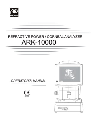
This Operator’s Manual contains information necessary for operating the NIDEK Refractive
Power/Corneal Analyzer ARK-10000 (OPD-Scan II).
The device complies with ISO 10342: 2010 Clause 4.
This manual includes operating procedures, safety precautions, and specifications.
The dioptric powers are indicated with reference wavelength Od = 587.56 nm.
For correct use, this manual is needed. Especially, cautions for safety and operating procedures
must be thoroughly understood before using the instrument.
Keep this manual handy to verify use whenever necessary.
If you encounter any problems or have questions about the instrument during use, please
contact your authorized distributor.
* OPD-Scan II is the common name of the ARK-10000 V2.00 or later.
4. Table of Contents
§1 INTRODUCTION .......................................................................................................Page
1-1
1.1 Outline of the Instrument ............................................................................................. 1-1
1.2 Intended Use .............................................................................................................. 1-1
1.3 Classifications ............................................................................................................. 1-2
1.4 Symbol Information .................................................................................................... 1-3
1.5 Preparing for Use ....................................................................................................... 1-4
§2 SAFETY ......................................................................................................................... 2-1
2.1 Storage, Transportation and Installation ....................................................................... 2-1
2.2 Plugging the Instrument In and Handling the Power Cord ............................................. 2-3
2.3 In Use ........................................................................................................................ 2-4
2.4 Maintenance ............................................................................................................... 2-7
2.5 Disposal ..................................................................................................................... 2-8
2.6 Connection to Network .............................................................................................. 2-8
2.7 Labels ........................................................................................................................ 2-9
§3 INSTRUMENT DESCRIPTION ................................................................................. 3-1
3.1 Names and Explanations of Parts ................................................................................ 3-1
3.2 Names and Explanations of Optional Function Screens .............................................. 3-19
§4 BASIC USAGE .............................................................................................................. 4-1
4.1 Operation Flow .......................................................................................................... 4-1
4.2 Power-ON and Power-OFF ...................................................................................... 4-3
4.2.1 Power-ON ....................................................................................................... 4-3
4.2.2 Reactivating instrument from power saving mode ................................................ 4-5
4.2.3 Power-OFF ...................................................................................................... 4-6
4.3 Selecting Measurement Mode ..................................................................................... 4-7
4.4 Measuring in ARK Mode ........................................................................................... 4-8
4.4.1 AR and KM measurements ............................................................................... 4-8
4.4.2 AR measurement ............................................................................................. 4-14
4.4.3 KM measurement ........................................................................................... 4-17
4.5 Measuring in ARK/CT Mode ................................................................................... 4-19
4.5.1 REF and CT measurements ............................................................................. 4-19
4.5.1.1 REF and CT measurements (Multiple measurement mode) ................... 4-29
4.5.2 REF measurement ........................................................................................... 4-35
4.5.2.1 REF measurement (Multiple measurement mode) ................................. 4-38
4.5.3 CT measurement ............................................................................................. 4-42
4.5.3.1 CT measurement (Multiple measurement mode) ................................... 4-45
4.6 Viewing Maps (Map View)....................................................................................... 4-49
4.6.1 Displaying map via measurement screen ........................................................... 4-49
4.6.2 Retrieving exam from database and displaying it in map .................................... 4-50
5. Page
4.6.3 Displaying map on another map set .................................................................. 4-52
4.6.4 Switching between right and left eyes ............................................................... 4-53
4.7 Printing ..................................................................................................................... 4-54
4.7.1 Printing measured data .................................................................................... 4-54
4.7.2 Printing color maps .......................................................................................... 4-56
4.8 Saving Measured Data ............................................................................................. 4-58
§5 HANDLING ADVANCED FUNCTIONS MORE EFFICIENTLY ............................ 5-1
5.1 Color Maps ............................................................................................................... 5-2
5.1.1 Axial map .......................................................................................................... 5-2
5.1.2 Instantaneous map ............................................................................................. 5-3
5.1.3 “Refractive” map ............................................................................................... 5-4
5.1.4 Elevation map ................................................................................................... 5-5
5.1.5 TopoClassifier map (Optional) ........................................................................... 5-9
5.1.6 Eye image ....................................................................................................... 5-15
5.1.7 OPD map ....................................................................................................... 5-16
5.1.8 Target “Refractive” map .................................................................................. 5-17
5.1.9 Internal OPD map ........................................................................................... 5-18
5.1.10 Wavefront High Order map ........................................................................... 5-20
5.1.11 Wavefront Total map ..................................................................................... 5-21
5.1.12 Wavefront Group map ................................................................................... 5-22
5.1.13 Zernike graph ................................................................................................ 5-25
5.1.13.1 RMS graph ....................................................................................... 5-25
5.1.13.2 Coefficient graph ............................................................................... 5-28
5.1.14 Difference map .............................................................................................. 5-30
5.1.15 Table at the bottom of Map View screen ........................................................ 5-30
5.2 Specifying Maps in Advance (Map View settings) ..................................................... 5-31
5.2.1 Setting “View 1”, “View 2” and “View 3” ......................................................... 5-31
5.2.1.1 Assigning entered map set to “View1”, “View2” and “View3” ............... 5-32
5.2.1.2 Entering new map set .......................................................................... 5-34
5.2.1.3 Modifying existing map set ................................................................... 5-37
5.2.1.4 Entering modifications made on Map View Settings screen
to map set ........................................................................................... 5-38
5.2.1.5 When selecting Wavefront Group map ................................................. 5-39
5.2.1.6 When selecting Zernike graph and displaying RMS graph ..................... 5-43
5.2.1.7 When selecting Zernike graph and displaying
Coefficient graph ................................................................................. 5-47
5.2.1.8 When selecting Difference map ............................................................ 5-53
5.2.1.9 Deleting map set .................................................................................. 5-54
5.2.2 Setting color scale ........................................................................................... 5-55
5.2.3 Displaying PSF ............................................................................................... 5-58
5.2.4 Other settings related to maps .......................................................................... 5-59
5.3 Changing Displayed Maps (Map View) ..................................................................... 5-62
5.3.1 Changing map types and overlay options ................................................. 5-63
5.3.2 Changing color scale (Select color scale) ................................................ 5-67
5.3.3 Changing exam displayed on map to another exam No. ........................... 5-69
5.3.4 Magnifying map ...................................................................................... 5-70
6. Page
5.3.5 Checking distance between two points .................................................... 5-70
5.4 Displaying Difference Map ........................................................................................ 5-71
5.5 Manual Pupillary Distance (PD) Measurement........................................................... 5-72
5.6 Database .................................................................................................................. 5-73
5.6.1 Importing external data into database (Import) ................................................. 5-73
5.6.2 Outputting exam from database (Export) .......................................................... 5-76
5.6.3 Editing data ..................................................................................................... 5-83
5.6.3.1 Editing patient data (Edit Patient Information) ....................................... 5-83
5.6.3.2 Editing exam data (Edit Exam Information) ........................................... 5-84
5.6.3.3 Deleting data (Delete) .......................................................................... 5-84
5.7 OPD Database Manager .......................................................................................... 5-86
5.7.1 Creating new database (in the ARK-10000) .................................................... 5-86
5.7.2 Changing database (Select Database) .............................................................. 5-89
5.7.3 Using database in another ARK-10000 on network ......................................... 5-91
5.7.4 Backing up database (Database Backup) ......................................................... 5-93
5.7.5 Rebuilding database (Rebuild Database) .......................................................... 5-96
5.7.6 Setting location for data backup, import, and export ......................................... 5-99
5.7.7 Setting data deletion criteria (Backup Settings) ............................................... 5-103
5.7.8 List of connected computers .......................................................................... 5-105
5.7.9 List of computers that have been connected ................................................... 5-106
5.8 Outputting Map Data .............................................................................................. 5-108
5.8.1 Outputting numerical data from map (Save Map Information) ......................... 5-108
5.8.2 Outputting map images (Save Map Image) ..................................................... 5-110
5.9 Accommodation Measurement Function (Optional) ................................................. 5-112
5.9.1 Setting accommodation stimulus ..................................................................... 5-112
5.9.2 Accommodation measurement ....................................................................... 5-114
5.9.3 Display of accommodation measurement result ............................................... 5-116
5.10 Wavefront Contact Lens Measurement Function (Optional) ................................... 5-117
5.11 Editing Detected Edges (Tools) ............................................................................. 5-120
5.11.1 Entering edge edit mode .............................................................................. 5-120
5.11.2 Adjusting curved edge (Move) ..................................................................... 5-121
5.11.3 Moving end point (Extend) .......................................................................... 5-122
5.11.4 Closing gap (Close) ..................................................................................... 5-123
5.11.5 Erasing edges (Erase) .................................................................................. 5-124
5.12 Editing Detected Pupil Edge .................................................................................. 5-125
5.12.1 Entering pupil edge edit mode ...................................................................... 5-125
5.12.2 Erasing edges (Erase) .................................................................................. 5-126
5.12.3 Moving pupil edge (Move) .......................................................................... 5-127
5.12.4 Finishing editing pupil edge .......................................................................... 5-127
5.13 Settings ................................................................................................................ 5-128
5.13.1 Setting parameters (Settings) ....................................................................... 5-128
5.13.2 Setting date and time ................................................................................... 5-136
5.13.3 Selecting whether or not to assign patient ID automatically ............................ 5-136
5.14 Formatting Floppy Disk ........................................................................................ 5-139
5.15 Transmitting Data to Refractor Through Cable ....................................................... 5-142
5.15.1 Transmitting day measurement data .............................................................. 5-143
5.15.2 Transmitting night measurement data as well ................................................. 5-144
7. Page
5.16 Exporting Data to Automatic Optometry System Using Eye Care Card .................. 5-146
5.16.1 Exporting day measurement data ................................................................. 5-147
5.16.2 Exporting night measurement data as well ..................................................... 5-149
§6 TROUBLESHOOTING GUIDE .................................................................................. 6-1
§7 MAINTENANCE .......................................................................................................... 7-1
7.1 Replacing Roll of Printer Paper ................................................................................... 7-1
7.2 Attaching Stack of Chinrest Paper ............................................................................... 7-3
7.3 Replacing Fuses ......................................................................................................... 7-4
7.4 Checking Measurement Accuracy ............................................................................... 7-5
7.5 CT Measurement Calibration ...................................................................................... 7-6
7.6 Cleaning Exterior ........................................................................................................ 7-7
7.7 Cleaning Measurement Window .................................................................................. 7-8
7.8 List of Parts for Replacement ...................................................................................... 7-8
§8 DISINFECTING PROCEDURES ............................................................................... 8-1
§9 SPECIFICATIONS ....................................................................................................... 9-1
§10 ACCESSORIES .......................................................................................................... 10-1
10.1 Standard Accessories ............................................................................................. 10-1
10.2 Optional Accessories .............................................................................................. 10-1
APPENDIX. A GLOSSARY .................................................................................................. A-1
APPENDIX. B INSTALLATION ......................................................................................... B-1
APPENDIX. C OBTAINING RELIABLE EXAM DATA .................................................. C-1
APPENDIX. D BEFORE FIRST BACKUP PROCEDURES ............................................. D-1
APPENDIX. E POINTS TO NOTE WHEN UTILIZING INTERNAL OPD MAP .......... E-1
APPENDIX. F EMC (ELECTROMAGNETIC COMPATIBILITY) .................................. F-1
8. §1 INTRODUCTION
1.1 Outline of the Instrument
The ARK-10000 measures the refractive condition and analyzes corneal shape of the patient’s eye.
The refractive condition is measured by weak infrared rays, and corneal shape is analyzed based on
placido rings projected onto the cornea.
The ARK-10000 has two measurement modes: ARK mode and ARK/CT mode.
In the ARK mode, AR- and KM-measured data are obtained and printed out.
AR-measured data: Refractive power in the central area of the eye that is equal to the data
obtained by an auto refractometer.
KM-measured data: Keratometry data simulated by the analyzed result of a captured placido
ring image.
In the ARK/CT mode, the curvature radius and refractive power of the whole eyeball are measured
and the measured data is displayed in color maps. The obtained examination data is stored in the built-
in database for future display of it in color maps.
The ARK-10000 has a main body and a measuring unit integrated on one base. On the base is a chin
rest on the patient’s side and a floppy disk drive on the operator’s side which is used to store measured
results and the maps of corneal shape. On the main body is a joystick and a printer*1 which prints
measured results. On the patient’s side of the measuring unit are placido rings, while a display is on the
operator’s side. The touch-screen panel not only displays a patient’s eye and measured data, but
allows the operator to control the instrument through the screen.
1.2 Intended Use
The OPD-Scan™ is a diagnostic instrument that is indicated for use:
• Mapping of refractive power distribution of the eye, by measurement and analysis of spherical power,
cylindrical power, and cylinder axis.
• The measurement and analysis of corneal curvature (corneal refractive power), cylindrical power,
and cylinder axis of the cornea. Mapping and display of the corneal shape, and screen out possibility
of having corneal diseases or conditions.
*1 The built-in printer prints out AR-measured data etc. To print a map of corneal shape, an optional
color printer is needed.
9. 1-2
1.3 Classifications
[Classification under the provision of 93/42/EEC (MDD)] Class a
The ARK-10000 is classified as a Class a instrument.
[Form of protection against electrical shock] Class
The ARK-10000 is classified as a Class instrument. A Class instrument is an instrument in
which protection against electric shock does not rely solely on basic insulation. The Class instrument
includes additional safety precautions that provide for the connection of accessible conductive parts
to a protective (earth) grounding conductor in the fixed wiring of the installation.
Use a power outlet which is equipped with a ground terminal.
[Degree of protection against electrical shock] Type B
The ARK-10000 is classified as a Type B instrument.
A Type B instrument provides an adequate degree of protection against electrical shock, particularly
regarding the following:
- allowable leakage currents
- reliability of the protective earth ground connection (if applicable)
[Degree of protection provided by enclosures] IP20*2
The ARK-10000 is classified as an IP20 instrument*2 , as such does not provide protection with
respect to harmful effects due to the ingress of water although it is protected against access to
hazardous parts with a solid matter such as a finger of 12.5mm in diameter. Avoid immersion of any
type.
[Degree of protection against flammability]
The ARK-10000 is classified as an instrument not suitable to be used in a potentially flammable
environment.
Do not operate the instrument near flammable type materials.
[Method(s) of sterilization or disinfection recommended by the manufacturer]
The forehead rest and chin rest can be cleaned with a cloth dampened with disinfecting alcohol as
necessary.
[Mode of operation]
Continuous operation
*2 In accordance with IEC 60529
10. 1-3
1.4 Symbol Information
This symbol on the instrument indicates that caution must be taken, and it is necessary to refer
to a related description in the Operator’s Manual before operating parts with this symbol.
This indicates that the instrument is classified as a type B instrument.
This symbol indicates the state of the power switch. If the symbol side of the switch is flipped
down, power is supplied to the instrument.
This symbol indicates the state of the power switch. If the symbol side of the switch is
pressed down, power is not supplied to the instrument.
This symbol indicates the fuse rating.
This symbol indicates that the instrument must be supplied only with alternating current.
This symbol indicates that printer paper can be torn by pulling it toward the arrow.
This symbol indicates the keyboard connector.
This symbol indicates the mouse connector.
This symbol indicates the network connector.
This symbol indicates the connector for data communication.
This symbol indicates the printer (option) connector.
This symbol indicates the connector for an external monitor etc.
This symbol indicates the connector for a USB device.
This symbol indicates that this product shall be disposed of in a separate collection of electrical
and electronic equipment in EU.
11. 1-4
1.5 Preparing for Use
1. Connect the cable of the keyboard to the
keyboard connector.
2. Set a roll of printer paper.
See “7.1 Replacing Roll of Printer Paper” for the
method.
3. Connect the power cord to the power
connector and the power outlet.
4. Set a stack of chinrest paper.
See “7.2 Attaching Stack of Chinrest Paper” for
the method.
Power connector Keyboard connector
12. §2 SAFETY
In this manual, the signal, CAUTION is used to designate and indicate a degree or level of
safety hazards or damages. The definition is as follows.
CAUTION: Indicates a potentially hazardous situation which, if not avoided,
may result in minor or moderate injury or a property damage
accident.
Even cases when CAUTION is given may result in serious injury under certain
conditions. Be sure to observe the instructions for CAUTION.
2.1 Storage, Transportation and Installation
CAUTION
• Never store the instrument in a place where water may splash or poisonous gas or liquid is
present.
• Never store the instrument in a place exposed to dust, direct sunlight, or hot and humid
surroundings.
• Never pull the power cord to move the instrument.
An injury or a failure of the instrument may result.
• To carry the instrument to another location, its base should be held from both sides by two
persons. (Never hold the forehead rest, main body, or measuring unit.)
If the instrument is carried only by one person, or a part other than the base is held, an injury
or a failure of the instrument may result.
• To transport the instrument, store it in the attached shipping carton without locking the measuring
unit to the base.
A breakdown of the instrument may result.
• Store the instrument in a place where it cannot be splashed with water.
Exposure to water may result in an electric shock or a failure of the instrument.
• Install the instrument on a stable and level place which is not subjected to vibration or shock.
Incorrect measurement or a failure of the instrument may result. An injury from the instrument
being knocked over by a shock may also result.
• Keep the touch screen panel away from direct sunlight or excessive ultraviolet rays.
They will damage the touch-screen panel.
• Install the device in area where the outlet that the power plug is inserted into is easily accessible
during use. In addition, ensure that the power plug can be disconnected without the use of a tool.
Otherwise, it may interfere with disconnection of the device from the input power source in
case of abnormality.
13. 2-2
CAUTION
• Install the instrument under the following conditions:
Dust-free environment
Disturbance-light-free environment
Vibration-free and shock-free environment
• Install and use the instrument in a place where the temperature and humidity are maintained to the
following:
Use conditions: Temperature: 10 to 35 ºC
Humidity: 30 to 75% (Non-condensing)
• The instrument has been tested and found to comply with the limits for medical devices
to the IEC 60601-1-2: 2001. These limits are designed to provide reasonable protection
against harmful interference in a typical medical installation. This instrument generates, uses and
can radiate radio frequency energy and, if not installed and used in accordance with the instructions,
may cause harmful interference to other devices in the vicinity. However, there is no guarantee
that interference will not occur in a particular installation. If this instrument does cause harmful
interference to other devices, which can be determined by turning the instrument off and on, the
user is encouraged to try to correct the interference by one or more of the following measures:
- Reorient or relocate the receiving device.
- Increase the separation between the instruments.
- Connect the instrument to an outlet on a circuit different from that to which the other
device(s) are connected.
- Consult the manufacturer or field service technician for help.
• In installation and operation of the device, observe the following instructions about EMC
(electromagneticcompatibility):
- Do not use the device simultaneously with other electronic equipment to avoid electromagnetic
interference with the operation of the device.
- Do not use the device near, on, or under other electronic equipment to avoid electromagnetic
interference with the operation of the device.
- Do not use the device in the same room with other equipment such as life-support equipment,
other equipment that has major affects on the life of the patient and results of treatment, or
other measurement or treatment equipment that involves small electric current.
- Do not use the device simultaneously with portable and mobile radio frequency
communication systems because it may have an adverse effect on operation of the device.
- Do not use cables and accessories that are not specified for the device because that may
increase the emission of electromagnetic waves from the device or the system and decrease
the immunity of the device to electromagnetic disturbance.
• The International Electrotechnical Commission sets the essential requirements for electrical and
electronic equipment that may disturb, or be disturbed by, other equipment. The ARK-10000
complies with these requirements as tabled on pages F-1 to F-3. Follow the guidance in the
tables for use of the device in an electromagnetic environment.
14. 2-3
2.2 Plugging Instrument In and Handling Power Cord
CAUTION
• Use power outlets which meet the specified power requirements.
If voltage is too high or low, the instrument may not deliver full performance, or a failure or a
fire may result.
• Do not overload one electrical outlet.
A fire may result.
• Never use a table tap or extension cable to supply the device with power.
The electrical safety may be lowered.
• Be sure to use a (HOSPITAL GRADE) power outlet equipped with a grounding terminal in
order to avoid an electric shock or a fire in the event of a power leak.
• Insert the mains plug into an outlet as far as the pins of the plug go.
Imperfect connection may result in a fire.
• If the instrument will not be used for a long period, disconnect the mains plug from the outlet.
A fire may result.
• Be sure to hold a plug instead of holding its cord when disconnecting the plug from an outlet.
A break in the metal core inside the cord may cause a short circuit or an electric shock.
• Do not crush with heavy objects nor squeeze the power cord.
The damaged power cord may cause an electric shock or a fire.
• If the internal wires of the power cord are exposed, power to the instrument is turned ON or
OFF when the power cord is moved, or the cord or the plug gets extremely hot, the power cord
itself is damaged. Immediately discontinue use of the power cord, and replace it with a new
one.
Otherwise, the power cord may cause an electric shock, or a fire.
• Clean between the prongs of the mains plug using a dry cloth every once in a while.
If dust settles thickly on them, it is likely to attract moisture, and may cause a short circuit, or
a fire.
• Do not use any power cord other than the specified one that comes with the instrument. Do not
use the specified power cord for any other instrument.
Failure or a fire may result.
15. 2-4
CAUTION
• When connecting the device to the PC* that does not comply with IEC60601-1, be sure to
supply power through an isolation transformer. (*Except for the PC that adopts the class II AC
adapter certified with IEC60950-1.)
Electric shock may occur. For installation of the isolation transformer, consult NIDEK or your
authorized distributor.
• When connecting to peripheral equipment like a PC with LAN connector via a medical facility
network, insert or connect the isolation transformer between medical electrical equipment an
network device (such as HUB), or networked device and other electrical equipment.
Depending on the types or numbers of other electrical equipment may occur.
For installation of the network isolation transformer, consult NIDEK or your authorized
distributor.
2.3 In Use
CAUTION
• Do not allow the patient to touch the placido ring unit on the patient’s side inadvertently.
Because the placido ring unit moves up, down, to the left, or to right during automatic
alignment, do not insert fingers under the unit. Fingers may be pinched in a space
between the bottom of the placido ring unit and rear panel of the main body and injured.
• Check the external view and operation of the instrument before use. If any abnormality is found,
do not use the instrument.
Use of an abnormal instrument may not produce the intended result or cause unexpected
health hazard by unexpected malfunction or wrong diagnosis.
• Wipe the forehead rest and chin rest before every measurement with a cloth dampened with
disinfecting alcohol. Remove a sheet of chin rest paper if a pad of the paper is mounted on the
chin rest.
• Never smear the measuring window with fingerprints, dust, or such.
The smeared window will result in extremely lower measurement accuracy.
• Never use the instrument for other than its intended use.
NIDEK assumes no responsible for any accidents or failures caused by the neglect of this
instruction.
• The objective refraction measured by the ARK-10000 is intended to be used as a reference of
lens prescription for the correction of visual acuity with spectacle or contact lenses. Subjective
refraction must also be used as the basis for spectacle or contact lens prescription.
• Never eject a floppy disk while the lamp of the floppy disk drive is being illuminated.
Damage to the floppy disk or disk drive may result.
16. 2-5
CAUTION
• When turning OFF the instrument, be sure to follow the instructions in “4.2.3 Power-OFF”
instead of turning OFF the power switch.
Turning OFF the power switch before Windows is shut down may result in a loss of data or a
malfunction.
• While the pointer ( ) is changed into the hourglass ( ), do not perform any operation through
the touch-screen panel.
A malfunction may result or the system may lock up.
• The ARK-10000 runs on Windows OS of Microsoft Corporation. Follow general precautions
in using Windows.
For example, before shutting the computer OFF, make sure that Windows is shut down.
• Operators are responsible for managing their data.
NIDEK assumes no responsibility for a loss of data.
• Be sure to back up measured data on storage disks such as a ZIP disk or DVD-RAM.
In case of the corruption of the built-in hard disk, saved data will never be usable again. In
addition, storage disks such as CD-R, CD-RW, DVD-R which need writing software are
improper for data backup.
• Do not touch the touch-screen panel with anything other than fingers or the tip of a touch-screen
pen.
Contact of a hard or sharp object such as a ball point pen with the panel may scratch the
panel. In addition, although the tip of a touch-screen pen is covered with resin which is
unlikely to scratch the panel, the panel may be scratched by strongly pressing the pen against
the panel.
• Never press two or more points on the touch-screen panel at the same time.
A malfunction may result.
• In case of an instrument failure, disconnect the power cord from the outlet, and contact your
authorized distributor without touching the internal structure of the instrument.
• Do not install Windows application software other than the ARK-10000 software.
The installation of any other Windows application software may lead to abnormal operation
of the ARK-10000 and loss of stored data. In addition, the warranty may not cover the
ARK-10000 if Windows application software other than the ARK-10000 software is installed.
• Turn OFF power to the instrument and put a dust cover over the instrument while it is not in use.
Accumulated dust, dirt, etc. may adversely affect measurement accuracy.
• Never disassemble or touch the internal structure of the instrument.
An electric shock, or a failure of the instrument may result.
• This device is classfied as Group 1 set by ISO 15004-2: 2007 Light Hazard and comforms to
the standard.
17. 2-6
{ Patient environment
The patient environment is the volume of space in which contact can occur between the patient and
any part of the device (including connected devices) or between the patient and any other person(s)
touching the device (including connected devices).
Use devices that comply with IEC60601-1 in the patient environment. If any device that does not
comply with IEC60601-1 is to be used, use an isolating transformer or common protective grounding.
Radius of 1.5 m
2.5 m
1.5 m 1.5 m
18. 2-7
2.4 Maintenance
CAUTION
• Before the replacement of fuses, turn OFF power to the instrument and disconnect the power
cord from the outlet.
An electric shock may result.
• Use only fuses of the specified rating.
A fire may result.
• Pay attention not to change the numbers in the voltage indication window while replacing fuses.
Accidental changing of improper voltage may result in a failure or a fire.
• Only the NIDEK service personnel or those who have been trained by NIDEK are allowed to
repair or disassemble the instrument.
• Never use organic solvents such as a thinner, or detergents with abrasives to clean the covers,
touch-screen panel, and placido rings.
The covers or touch-screen panel may be corroded or scratched. Especially, cleaning
of the placido rings with organic solvents or detergents with abrasives will disturb
concentric ring shapes, which may lower measurement accuracy.
• If the touch-screen panel becomes dirty, soak a soft cloth or gauze in water, wring it well, and
wipe the panel with it.
• Blow the dust off the placido rings with a blower.
Careless wiping may disturb concentric ring shapes, and may lower the measurement accuracy.
NOTE
• There may be a few “missing” or “dead” pixels in your touch-screen panel, which appear
as black dots on an all-white background or there may be “lit” pixels, which appear as
ones or several randomly-placed red, blue and/or green pixel elements on an all-black
background.
This does not represent a failure of the touch-screen panel; This is due to the structure
of the liquid crystal display.
19. 2-8
2.5 Disposal
NOTE
• Follow local governing ordinances and recycling plans regarding disposal or recycling of
device components.
The instrument uses a lithium battery mounted on a board inside. Follow your local
governing ordinances in disposing of the lithium battery since the disposal method
differs according to the local government. Inappropriate disposal may contaminate the
environment.
• When disposing of packing materials, sort them by material and follow local governing
ordinances and recycling plans.
Inappropriate disposal may contaminate the environment.
2.6 Connection to Network
CAUTION
• If this instrument is used with other software such as OPD-Station to share the database, do not
connect them to the network that can connect to the Internet.
Configure a local network only with related instruments and software such as this instrument,
OPD-Station, and Final Fit. NIDEK will not assume responsibility or compensate for damages
caused by any virus infection and development due to connection of the instrument to a network
that can connect to the Internet.
This instrument is a medical equipment. If the user changes the setting of the instrument by
installing other software such as antivirus software, NIDEK will not guarantee proper operation
of the instrument.
20. 2-9
2.7 Labels
[Right side view]
See “2.2 Plugging Instrument In and
Handling Power Cord” (p.2-3).
See “2.2 Plugging Instrument In and
See “2.5 In Use” (p.2-5). Handling Power Cord” (p.2-3).
See “2.4 Maintenance” (p.2-7).
22. §3 INSTRUMENT DESCRIPTION
3.1 Names and Explanations of Parts
Touch-screen panel
Start button
Joystick
Locking knob
Floppy disk drive
Operator’s side
Touch-screen panel Floppy disk drive
Displays various kinds of operation screens, Used to store map images or numerical data
exam data, and maps. obtained from measurements on a floppy disk.
Touching the displayed buttons allows Use a MS-DOS-formatted 2HD 3.5-inch
operation of the instrument. floppy disk.
Start button Printer
Used to start the measurement. The built-in printer is used to print out the AR-
and KM-measured data (equivalent to the mea-
Joystick sured values by Auto Ref/Keratometer).
Used to move the main body to the right, left,
back and forth. By turning the top of this le- Mouse connector
ver, the main body can be moved up and down. Used to connect a mouse.
Connectable mouse type: PS/2 mouse
Locking knob
Used to fix the main body to the base unit. Printer connector
To lock the main body, bring the main body Used to connect an optional color printer.
to the center of the base unit, and turn the
knob counterclockwise while holding it down. Ethernet connector
To temporarily lock the body at any position,
Used to connect the instrument to Ethernet. To
turn the knob clockwise.
do this, it is necessary to set Windows. (In “Net-
Do not lock the main body with this locking
work Connections” in “Control Panel”, the right
knob when transporting the instrument.
connector is set to “Local Area Connection”, and
Breakage of the instrument may result.
the left connector to “Local Area Connection 2”.)
23. 3-2
Printer
PD window
Mouse connector
Power switch
Printer connector
Fuse
Ethernet connector
AC inlet
USB connector
Right side view VGA connector
COM connector
Keyboard connector
USB connector Keyboard connector
This connector is for connecting an USB device. Used to connect the keyboard.
Used to connect an external storage device.
Power switch
VGA connector
Flip the power switch to the “ | ” side to turn
Used to connect an external monitor or video
the instrument ON.
printer.
When turning it OFF, be sure to press
on the touch-screen panel instead of pressing
COM connector this switch. After Windows has stopped all
Used to connect an interface cable when trans- its operations, the instrument automatically
mitting data to the refractor, NIDEK RT-2100/ shuts off.
RT-5100, or an external computer.
CAUTION
• Equipment connected to the analog or digital interfaces must be certified according to the
representative appropriate national standards (such as EN 60601-1 and IEC 60601-1.)
Furthermore, all configurations shall comply with the system standard IEC 60601-1-1.Anyone
who connects additional equipment to the signal input part or signal output part configures a
medical system, and is therefore responsible that the system complies with the requirements
of the system standard IEC 60601-1-1. If in doubt, consult the technical service department
or your local representative.
24. 3-3
Forehead rest
Placido rings
Eye level marker
Measuring window
Chin rest
Chin rest knob
Patient’s side
Eye level marker
A guide for the patient’s eye level during mea-
surement. The height of the chin rest should be
adjusted so that the center level of the patient’s
eye roughly aligns with this line.
Chin rest knob
Turning this knob moves the chin rest up and
down. You may use the eye level marker as a
guide to adjust the patient’s eye level to a com-
fortable height for measurement.
25. 3-4
[Measurement screen (ARK mode)]
The screen is displayed when the refractive power and curvature radius of the eye are measured.
Target
Focusing indicator Alignment light
Measurement select button
Measurement mode button Tracking button
Auto-shot button
Measurement select button : The auto-shot function is turned OFF.
Every time the button is pressed, the measure- : The auto-shot function is turned ON
ment type is selected in the order of (AR (active).
and KM measurements) => (AR measure- The button cannot be changed into if
ment) => (KM measurement) => the tracking button is .
(Manual PD measurement*5). The auto-shot function is disabled during
: Both AR and KM measurements KM measurement.
: Only AR measurement
: Only KM measurement Tracking button
: Manual pupillary distance measurement Used to toggle the auto-tracking function.
: The instrument automatically aligns the
Measurement mode button measuring unit with a patient’s eye.
Used to toggle between the (ARK mode) : The auto-tracking function is not active.
and (ARK/CT mode). * Auto-tracking function: When roughly
aligned to the corneal vertex point, the
Auto-shot button ARK-10000 automatically detects the
Used totoggle the auto-shot function. corneal vertex point, and it performs a
fine alignment and focusing.
*5 The button is selectable only when the “Auto PD” check box is unchecked on the Settings
screen.
26. 3-5
Used to print out measured exam data with
the built-in printer.
While the data is temporarily saved in the
memory, the button is marked by a small
circle in the upper right corner like .
When starting a measurement after press-
ing the button, the instrument clears the
saved data in the memory, and starts mea-
surement.
Used to delete the exam data which is being
displayed on the screen.
Used to switch the screen to the Settings
screen where various settings can be speci-
fied.
Used to exit the ARK-10000 software and turn
the instrument OFF.
Be sure to use this button when turning
the instrument OFF. Never turn the instru-
ment OFF by pressing the power switch
as it may result in a malfunction.
Used to display on-screen help related to the
screen.
27. 3-6
[Measurement screen (ARK/CT mode)]
The screen is displayed when the refractive power and curvature radius of the eye are measured.
Target
Focusing indicator Alignment light
Measurement select button
Measurement mode button Auto-shot button Tracking button
Measurement select button Auto-shot button
Every time the button is pressed, the measure- Used to toggle the auto-shot function.
ment type is selected in the order of (REF : The auto-shot function is turned OFF.
and CT measurements) => (REF measure- : The auto-shot function is turned ON
ment) => (CT measurement) => (active).
(Manual PD measurement*6). The button cannot be changed into if
: Both REF and CT (Corneal Topog- the tracking button is .
raphy) measurements The auto-shot function is disabled during
: Only REF measurement CT measurement.
: Only CT (Corneal Topography) mea-
surement
Tracking button
: Manual pupillary distance measurement
Used to toggle the auto-tracking function.
: The instrument automatically aligns the
Measurement mode button
measuring unit with a patient’s eye.
Used to toggle between (ARK mode) and : The auto-tracking function is not active.
(ARK/CT mode). * Auto-tracking function: When roughly
aligned to the corneal vertex point, the
ARK-10000 automatically detects the
corneal vertex point, and it performs a
fine alignment and focusing.
*6 The button is selectable only when the “Auto PD” check box is unchecked on the Settings screen.
28. 3-7
Used to print out exam data such as AR data Used to display on-screen help related to the
and corneal curvature radius with the built-in screen.
printer, and to save the data into the database.
While the data is temporarily saved in the Detection in progress display
memory, the button is marked by a small The “ ” mark (red) is displayed while the de-
circle in the upper right corner like . tection of the placido rings is in progress. The
When starting a measurement after press- “ ” mark (gray) is displayed while the detec-
ing the button, the instrument clears the tion of the pupil is in progress.
saved data in the memory, and starts mea- If two or more readings are in progress, the num-
surement. ber is displayed on the side of the mark.
When exam data has been saved in the data- (Example: The indication “ ” is dis-
base after printout, the button changes into played when two readings of pupil are in
. progress.)
In Multiple measurement mode, pressing this
button displays the Data Selection screen. ID: and Patient buttons
Used to open the “Select Patient” dialog box for
patient data entry (such as a patient name) or
Used to switch the screen to the Map View patient data selection.
screen. After entering patient data, the ID No. and
The latest exam data will be displayed in the patient name are displayed on the buttons.
map layout of “View 1”.
Used to delete the exam data which is being dis-
played on the screen.
Used to switch the screen to the Patient Selec-
tion screen.
Used to switch the screen to the Settings screen
where various settings can be specified.
Used to exit the ARK-10000 software and turn
the instrument OFF.
Be sure to use this button when turning
the instrument OFF. Never turn the instru-
ment OFF by pressing the power switch as it
may result in a malfunction.
29. 3-8
[Map View screen]
The Map View screen can include 6 maps at the maximum. Because 6 maps cannot be fit into
the screen at a time, scroll through all the maps using the scroll bar on the right side to view the six
maps.
In addition, pressing below the color scale of each map enlarges that map only.
The available map types are: Axial map, Instantaneous map, “Refractive” map, Elevation
map, OPD map, Target “Refractive” map, Internal OPD map, Wavefront High Order map,
Wavefront Total map, Wavefront Group map, Zernike graph and Difference map. On the screen,
the Eye Image can also be displayed in stead of a map. (Selectable on the Map View Settings
screen.)
Scroll bar
Used to print out a map image with an optional Used to toggle the eye maps (Left/Right).
color printer. The button is operative only when data of both
When exam data is stored in a database eyes is obtained with the same Exam No.
after printout, the button changes into .
Used to go to the screen where a map set (al-
Used to output a map image into a file in the ready entered map layout) of both left and
JPEG format or the BMP format. right eyes is selected.
Used to output numerical data of measured Used to go to the screen where a map set (al-
results into a text file in the CSV format. ready entered map layout) is selected.
30. 3-9
Used to go to the Map View Settings screen
where map types, layouts, color scales and so
on are specified.
Used to exit from the Map View screen to the
measurement screen, or to the Patient Selec-
tion screen.
Used to display on-screen help related to the
screen.
31. 3 - 10
[Data Selection screen]
On the Data Selection screen, sets of data to be saved are selected from those measured in Multiple
measurement mode. Pressing the desired sets of data to be saved selects it and frames it in green.
Pressing selected data again cancels selection of the data.
Eye direction box
Scroll bar
Scroll bar
32. 3 - 11
Eye direction box Data for each measurement
Used to toggle the Data Selection screen be- S, C, A: AR measurement value
tween the right and left eyes. RMS@3 mm: RMS in I 3 mm area
The numeric characters beside “R” and “L” RMS@5 mm: RMS in I 5 mm area
indicate the numbers of pairs being selected. (See “5.1.7 OPD map”.)
(An OPD data and a CT data makes a pair.) Pupil Size: Pupil diameter
Ex. 1 pr. = 1 pair Pupil Detect: Result of pupil edge detection
2prs. = 2 pairs Offset: Alignment deviation in OPD
measurement
All Off button Displayed in green when less than
Used to cancel all the selections. I 0.3 mm. Becomes yellow and
red as the deviation increases.
button
Used to magnify the map beside it.
Pupil image
Pupil images in mesopic vision.
Cyan line: pupil contour in mesopic vision
Axial map image
Cyan cross: pupil center in mesopic vision
Axial map with the Smolek-Klyce [1.5D] color
scale.
OPD map image
OPD maps with Adjustable, Common (Middle:
Pupil image
0.00), and AutoStep color scale.
Pupil images in photopic vision.
Violet line: pupil contour in photopic vision
Violet cross: pupil center in photopic vision
Cancel button
Used to return to the measurement screen with-
out saving the measured data.
Data for each measurement
The measured data are deleted.
Sim’ K1: Refractive power@angle along
the steepest meridian
Sim’ K2: Refractive power@angle along
New Exam button
the flattest meridian Used to return to the measurement screen to
Rings: The number of rings from the in- perform additional measurement.
ner ring detected without a gap.
TED: Result of check whether the iris Save button
image is applicable to the TED Used to save the selected sets of data in the da-
function in the EC-5000. tabase.
Pupil Detect: Result of pupil edge detection
Offset: Alignment deviation in CT mea- Save All button
surement Used to save all the sets of data in the database.
Displayed in green when less than
I 0.3 mm. Becomes yellow and
red as the deviation increases.
33. 3 - 12
[Display Data Selection screen]
On the Display Data Selection screen, sets of data to be displayed are selected from those selected
in the Data Selection screen.
Pressing the desired sets of data to be displayed selects it and its pair by framing them in green.
(When the measurement data was selected and saved in the Data Selection screen, the sets of OPD
and CT data are automatically paired in order of measurement. The formed pairs cannot be changed.)
Eye direction box
Scroll bar
Scroll bar
34. 3 - 13
Eye direction box Data for each measurement
Used to toggle the Display Data Selection screen S, C, A: AR measurement value
between the right and left eyes. RMS@3 mm: RMS in I 3 mm area
RMS@5 mm: RMS in I 5 mm area
button (See “5.1.7 OPD map”.)
Used to magnify the map beside it. Pupil Size: Pupil diameter
Pupil Detect: Result of pupil edge detection
Axial map image Offset: Alignment deviation in OPD
Axial map with the Smolek-Klyce [1.5D] color measurement
scale. Displayed in green when less than
I 0.3 mm. Becomes yellow and
red as the deviation increases.
Pupil image
Pupil images in photopic vision.
Pupil image
Violet line: pupil contour in photopic vision
Violet cross: pupil center in photopic vision Pupil images in mesopic vision.
Cyan line: pupil contour in mesopic vision
Cyan cross: pupil center in mesopic vision
Data for each measurement
Sim’ K1: Refractive power@angle along
OPD map image
the steepest meridian
Sim’ K2: Refractive power@angle along OPD maps with Adjustable, Common (Middle:
the flattest meridian 0.00), and AutoStep color scale.
Rings: The number of rings from the in-
ner ring detected without a gap. Cancel button
TED: Result of check whether the iris Used to return to the measurement screen with-
image is applicable to the TED out displaying maps in the Map View screen.
function in the EC-5000.
Pupil Detect: Result of pupil edge detection button
Offset: Alignment deviation in CT mea- Used to go to the Map View screen of the se-
surement lected data.
Displayed in green when less than
I 0.3 mm. Becomes yellow and
red as the deviation increases.
35. 3 - 14
[Patient selection screen]
The screen is for selecting exam data to be displayed on maps from the database. The screen
is also used for editing data.
By pressing an item on the top (ID, Name, Sex, Group, Last Exam Date) once, data can be
sorted in ascending order within the item field. Pressing the item once again sorts the data in
descending order. (ascending order) or (descending order) on an item indicates the
item on which the sort order is based.
Press any item on the desired patient line to select exam data.
Map Selection area
Number of
listed data items
Used to go to the Map View screen of the se- Used to display the Import (Outside to Inside)
lected data. screen through which data is imported.
The button is for importing exam data ob-
tained by another ARK-10000 into the data-
Used to go to the Map View Settings screen base of your ARK-10000.
where map types and a layout etc. are speci-
fied.
Used to display the Export (Inside to Outside)
screen through which data is output to stor-
Used to display the “Search Patient Data” dia- age disks such as a floppy disk etc.
log box.
Used to display the Delete screen through
Used to display the Edit Patient Information which data can be deleted.
screen where patient data is modified or the
Edit Exam Information screen where exam
data is modified.
36. 3 - 15
Number of listed data items
Used to display the “OPD Database Manager” Shows the total number of data items (A) and
dialog box on which to create, change, backup, the number of data items listed (B).
or rebuild the database. Patient Data 20 of 20 displayed
Number of data items listed (B) Total number of data items (A)
Used to open the “Database Settings” dialog box. When data is not retrieved by the “Search Pa-
tient Data” dialog box below, (A) equals (B).
Used to re-detect the edges of CT-measured Map Selection area
data saved in the database. Used to set a layout of the maps to be dis-
played on the Map View screen. See expla-
nation below for details.
Used to return to the measurement screen.
[“Map Selection” area]
Four operations available in the “Map Selection” area on the Patient Selection screen:
NOTE
• Specifications on the Patient Selection screen are temporarily applicable to a map. The map
set will be reset back to the one specified on the Map View Settings screen once you select
another patient. Specify a permanent map set that is applied to all the patients on the Map
View Settings screen.
I. Selecting a map layout from among the three map sets
(“View 1” to “View 3”) to be applied to the maps
displayed on the Map View screen
Select the desired map set to be used from among “View 1”,
“View 2” and “View 3” by pressing a radio button ( ).
The map button will represent the selected layout.
Radio button
Layout of “View 1”
Layout of “View 2”
Layout of “View3”
Map button
Whether or not a map is to be printed in the
layout is shown. In this case, the map is
printed in the “View 1” layout and “View 2”
layout.
37. 3 - 16
II. Changing a layout assigned to a map set (“View 1” to View 3”)
1) Select the button which is immediately
under the selected radio button of a map
set (“View 1” to “View 3”).
In the case of the figure on the right,
press AxOPD2 button.
The screen where a map layout can be
selected is displayed.
2) Press the desired layout to designate.
This is a temporary designation. The
designated layout will be reset back to
that of the “View” specified on the Map
View Settings screen when selecting
other patient data.
III. For a patient with multiple items of exam data, designating where to locate individual
maps
1) Designate exam data to be displayed.
Press the desired exam data line.
Map button
2) Designate a map position on which the
exam data will be displayed.
Press a map button to designate.
The designated map button No. will be
entered in the “Map No.” box in a
list.
3) Repeat Steps 1) to 2) to designate data
to be displayed and its map position.
This is a temporary designation. The
designated layout will be reset back to
that of the “View” specified on the Map
View Settings screen when selecting
other patient data.
IV. Selecting a map layout from “View 1” to “View 3” in which maps are printed by pressing
on the Map View screen
Select of “View 1” to “View 3”. Multiple selections of the buttons are allowed.
Ÿ Maps are printed in the layout.
Ÿ Maps are not printed in the layout.
This is a temporary designation. The designated layout will be reset back to that of
“View” specified on the Map View Settings screen when selecting another patient’s data.
Designate a map layout that is permanently applied in printing on the Map View Settings
screen.
38. 3 - 17
[“Search Patient Data” dialog box]
By using the “Search Patient Data” dialog box, the
operator can easily search for patient data which
meet all the entered specifications only and select
the desired patient’s data.
1) Press to display the “Search Patient Data”
dialog box.
2) Enter the desired specifications in the
corresponding fields and press .
ID, Name, Group Ÿ Only the data whose items contain the entered characters is searched.
Last Exam Date Ÿ Checking searches only for the data from the designated period back
from the last measurement date.
Today: Today’s data only
Week prior: Data obtained for the last 7 days
One Month prior: Data obtained for the last 30 days
Three Month prior: Data obtained for the last 90 days
Period: Data obtained during the date range designated in the “From” and “To” fields
Sex Ÿ Select “Male” (Male patients only are searched), “Female” (Female patients only
are searched), or “Both” (Both male and female patients are searched).
Patient data which meet all the entered specifications only is searched.
button: Used to exit to the Patient Selection screen without searching.
button: Used to return the specifications to the initial ones. (“ID”, “Name” and “Group”
fields will be blanked, “Both” of “Sex” will be selected, and “F Last Exam
Date” will be unchecked: The 1st day of the last month will be entered in the
“From” fields, and the current date will be entered in the “To” fields.)
F Save search specifications even after shutdown
If the check box is checked, the data searched with the dialog box will be saved even after
shutdown. To return the searched patient data to the previous status before searching, press
on the Search Patient Data dialog box to return the specifications to the initial ones, and
then press . If the check box is unchecked, the searched patient data is returned to the
previous state before searching when the Patient Selection screen is closed. Be aware that
this check box is not displayed and the searched data is not maintained when the Search
Patient Data dialog box is displayed by way of the Select Patient dialog box or Import (Outside
to Inside) screen.
On the condition that patient data is searched using the Search Patient Data dialog box, the
background color of the patient list is changed from white to yellow.
NOTE
• The Patient Selection screen cannot list more than 5,000 items of patient data. If the
patient number exceeds 5,000, enter a specification to narrow the scope of a search.
39. 3 - 18
[Settings screen]
This screen is used to make settings related to measurements, the built-in printer, communica-
tion and others. The screen is also used for exiting the ARK-10000, and for returning to the
Windows screen.
Used to go to the Calibration selection screen. Used to cancel modifications and to return to
Try not to press this button except when per- the measurement screen.
forming calibration for the CT measurement be-
cause changing the setting improperly results in a
malfunction of the instrument.
Used to display on-screen help related to the
screen.
Used to display the version of the ARK-10000
software.
Used to exit the ARK-10000 software and to
return to the Windows screen.
Used to fix modifications and to return to the
measurement screen.
40. 3 - 19
[OPD Database Manager screen]
This screen is used for selecting the desired database, database back-up, and such. This screen ap-
pears by clicking the button in the Select Patient screen, double-clicking the icon on the task
tray at the bottom right of the Windows screen, or clicking “Open OPD Database Manager” option
that appears by right-clicking the icon on the task tray.
<Normal Settings> <Advanced Settings>
Start button Linked Comp List button
Used to start connection of the device with the Used to display a list of computers connected to
database. the database.
After changing the settings in this screen, press This button is enabled when the selected data-
this button to start connection with the database. base is in the ARK-10000.
Stop button Advanced Settings/Normal Settings
Used to stop connection of the device with the Used to toggle the Advanced Settings and Nor-
database. mal Settings screens.
Before selecting or backing up database, stop
connection between the device and the database Minimize button
using this button. Used to minimize the OPD Database Manager
screen to the icon on the task tray.
Local and Other computer radio buttons
Used to toggle local database or database on an End button
external computer. Used to close OPD Database Manager.
Local – Database on the ARK-10000.
Other computer – Database on a OPD Data-
base Manager-installed ex-
ternal computer
41. 3 - 20
Backup button
Used to display the Database Backup screen
where the database can be backed up.
Setting button
Used to display the Backup Settings screen
where the criteria for deleting data sets in the
database can be set.
Rebuild button
Used to display the Rebuild Database screen
where database can be rebuilt.
“Enabling the entry of alphanumeric
characters only” check box
When the check is removed, patient names and
comments can be input in Japanese.
Be sure to check this box when using the Final
Fit software.
Characters other than alphanumeric characters
may become unreadable.
Ref... button
(in Local box of Advanced Setting screen)
Used to display the Select Database screen
where database setting or selection can be per-
formed.
Computer name box
Used to input the computer name to connect to.
The desired computer name can be selected from
the list that appears by clicking the triangle but-
ton shown to the right of the box.
Ref... button
Used to display the computer reference screen
where the desired computer to connect to can
be selected.
Server history button
Used to display a list of computers the device
connected with in the past. The desired com-
puter to connect to can be selected or the com-
puter names can be deleted from the list.
42. 3 - 21
3.2 Names and Explanations of Optional Function Screens
[Accommodation measurement (optional)]
This screen is used to measure the distribution of refractive power while applying the stimulus is to
accommodation.
Near/Far toggle button Chart position indicator Stimulus box
Measurement mode button
Near/Far toggle button Stimulus box
Used to toggle between (Far vision The amount of stimulus is set.
measurement) and (Near vision The default stimulus amount is set in the Set-
measurement). tings screen.
This value cannot be changed in the near vi-
sion measurement.
Chart position indicator
Indicates the current chart position.
Measurement mode button
F: SE value position in far vision measure-
ment Each pressing of this button changes the mea-
N: Target position in near vision measurement. surement mode in order of (ARK/CT
The position moved from the F position in mode), (ARK mode), and (Accom-
the near vision direction by the amount of modation measurement mode).
the stimulus.
The chart position cannot be changed in Near
vision measurement mode.
43. 3 - 22
[Wavefront Contact Lens measurement (optional)]
This screen is used to perform measurement to calculate data for wavefront-guided contact lens.
Fine adjustment button Input box Output Folder box
Results box
Pupil contour (blue line)
Pupil center (blue cross)
Marks
Fine adjustment button Output Folder box
Used to adjust the positions of the mark of the Destination of the output measurement result file
same color finely. is input.
Input box button
Lens ID: Used to open the Browse for Folder screen in
Displays the contact lens ID. which the destination of the output measurement
The contact lens ID is automatically applied file is selected to be displayed in the Output
from the patient ID, exam No., and measure- Folder box.
ment date.
Trial lens pwr (D):
Refractive power of the trial contact lens is
input.
Trial lens B.C.:
The base curve of the trial contact lens is se-
lected between “flat: 1” and “steep: 2”.
* The control window can be moved by dragging. Move the control window if it hides the marks on the
trial contact lens.
44. 3 - 23
Results box
Decentration:
Displays the positional deviation of the pupil
center from the center of the trial contact lens
in the unit of mm.
Horizontal:
Displays the deviation in the horizontal di-
rection. When the pupil center is deviated
to the right, the sign becomes “+.”
Vertical:
Displays the deviation in the vertical di-
rection. When the pupil center is deviated
upward, the sign becomes “+.”
Lens rot:
Displays the amount of rotation of the trial
contact lens. The horizontal position is 0º. The
sign is “+” when the trial contact lens is ro-
tated in counterclockwise direction.
Zernike at I *.* (—m):
The number after “I” indicates the diameter
of the area used for Zernike analysis. The box
below shows the wavefront RMS error.
OK button
Used to output the measurement result to the
destination selected in the Output Folder box.
R / L button
Used to toggle the right and left eyes.
The character in the button is displayed in blue
only when the REF measurement is performed
for both eyes.
If the “R/L Format” setting in the Settings screen
is “OD/OS”, this button is displayed as “ OD /
OS .”
button
Used to return to the measurement screen with-
out outputting the measurement result.
45. §4 BASIC USAGE
This section explains basic usages as:
Measuring the eye in the ARK mode. o Printing out measured data.
Measuring the eye in the ARK/CT mode o Viewing measured data displayed in a map. o
Saving the measured data in the database.
Recalling the measured data from the database and displaying it in the map.
Printout
Saving of
Measure of Display of
Mode Purpose data in
ment type measured maps
database
data
Refractive power and corneal curvature
radius in the central area of the eye are AR
measured. measurement, Not
ARK This mode is not for saving the measured KM Print Not save
display
data in the database but for printing KM- measurement
and/or AR-measured data.
Corneal curvature radius and the
distribution of the refractive power are
measured. This mode is for checking REF
ARK/ measurement,
the distribution of the refractive power of CT Print Display Save
CT the whole eyeball, saving it into the measurement
database and displaying it in maps in the
future.
Measurement
Details of measurement
type
Measures the refractive power of the central area of the eye in the same
AR measurement
manner that the auto refractometer does.
The placido ring image projected over the cornea is captured. From the
analysis result of the projected image, corneal curvature radius in the
KM measurement
approximately 3 mm area, the direction of the steepest meridian and the
amount of corneal astigmatism are obtained.
The fundus is scanned by slit-shaped ray bundles and data for displaying
REF measurement
the OPD map is obtained.
The placido ring image projected over the cornea is captured. From the
CT measurement analysis result of the projected image, a map illustrating the distribution
of the corneal curvature radius or the refractive power is obtained.
4.1 Operation Flow
[ Measuring the eye in the ARK mode. o Printing out measured data.]
4.2.1 Power-ON
Check the instrument before operation. (Step 4 of “4.2.1 Power-ON”.)
Measuring
4.4.1 AR and KM measurements
4.4.2 AR measurement
4.4.3 KM measurement
4.7.1 Printing measured data
4.2.3 Power-OFF
46. 4-2
[ Measuring the eye in the ARK/CT mode o Viewing measured data displayed in a map.
o Saving the measured data in the database.]
4.2.1 Power-ON
Check the instrument before operation. (Step 4 of “4.2.1 Power-ON”.)
Entering a patient name (Step 4, p4-20)
Measuring
4.5.1 REF and CT measurements
4.5.2 REF measurement
4.5.3 CT measurement
4.6.1 Displaying map via measurement screen
4.7.1 Printing measured data
(The measured data is saved in the database simultaneously with the printout of the
measured data.)
4.2.3 Power-OFF
[ Recalling the measured data from the database and displaying it in the map.]
4.2.1 Power-ON
4.6.2 Retrieving exam from database and displaying it in map
4.2.3 Power-OFF
47. 4-3
4.2 Power-ON and Power-OFF
4.2.1 Power-ON
1. Make sure that no floppy disk is inserted in
the disk drive.
2. When using an optional color printer, turn
it ON.
3. Turn ON the power switch of the ARK-10000.
Windows starts up and then the ARK-10000
also starts up. *7
Power switch
NOTE
• Because the ARK-10000 has Microsoft Windows installed, the instrument may be
started in “Safe Mode”, or “Scandisk” may be accidentally initiated on startup. In
such cases, follow the instructions below.
If the instrument starts in “Safe Mode” Ÿ
Turn OFF the instrument after startup and restart
it. See [Restarting the instrument in Safe Mode]
(p.4-5). If the instrument still starts in “Safe
Mode”, contact NIDEK or your authorized
distributor.
If “Scandisk” is initiated Ÿ Allow “Scandisk” startup. If the ARK-10000
does not start up properly after “Scandisk” has
ended, contact NIDEK or your authorized
distributor.
• If the built-in hard disk space is not enough at startup, a message appears during the
program startup to encourage the operator to back up data and to free up disk space by
deleting unwanted data. In this case, make more disk space as instructed:
Erase unwanted data.
Back up data on a storage disk as a ZIP disk or DVD-RAM and delete the backed
up data from the hard disk. See “5.7.4 Backing up database”.
• When backing up or rebuilding the database, connect an external storage device first,
turn it ON, and then turn the ARK-10000 ON (When designating an external storage
device as a target location for backup.).
If the external storage device has not been connected when turning the ARK-10000
ON, the storage device may not be function properly.
*7 Windows is the registered trademark of Microsoft Corporation, U.S.A.
48. 4-4
NOTE
· If the instrument power automatically turns off immediately after turning on the power
switch, start up the instrument by pressing the Reset button as described below.
While pressing the Reset button with the attached touch-screen pen, turn on the
power switch. Release the touch-screen pen from the Reset button after about two
seconds.
At this time, take care not to press the Reset button for an excessively long time as it
will turn off the power.
Do not press the Reset button during instrument use. Pressing it inadvertently shuts
down the instrument.
4. Check the instrument before operation.
Check the following points before operating the instrument.
- The error message is not displayed.
- The main body moves smoothly with the joystick.
- The measuring window is not soiled.
- Measurement accuracy (See “7.4 Checking Measurement Accuracy” (p.7-5).)
49. 4-5
[Restarting the instrument in Safe Mode]
When starting the instrument in Safe Mode, shut the instrument down once after startup and
restart it.
Be aware that the touch-screen panel does not function in the Safe Mode. Use the keyboard to
shut down the instrument as instructed below.
1) Press F4 key while pressing Alt key.
The “Shut Down Windows” dialog box
opens.
2) Make sure that the “Shut down” option is
selected.
If not, select the “Shut down” option with
n key or p key.
3) Press Enter key.
After a while, Windows is shut down and the instrument power is turned off automatically.
4.2.2 Reactivating instrument from power saving mode
The instrument will automatically be shut off for power conservation after a set period of time
of non-operation. In the power saving mode, the title screen will dim.
To reactivate the instrument from the power saving mode, do one of the following:
• Touch the touch-screen panel.
• Press any key of the keyboard.
• Press the start button.
• Manipulate the joystick to move the measuring unit to place it in front of the left eye or right
eye.
* According to the status of the screen, the instrument may not be put into the power saving
mode.
* The preset time of no operation can be set with the Settings screen. See “5.9.1 Setting
parameters”.
50. 4-6
4.2.3 Power-OFF
CAUTION
•When turning OFF the instrument, be sure to follow Steps 1 to 4 as below instead of
turning OFF the power switch.
Turning OFF the power switch of the instrument before Windows is shut down may
cause a loss of data, or a failure of the instrument. *6
If the instrument cannot be operated through the touch-screen panel or keyboard,
and therefore Windows cannot be shut down, turn OFF the power switch once, and
turn it ON again and confirm that the instrument operates properly.
1. Press on the measurement screen.
The “Shutdown” dialog box opens.
2. Press OK .
The ARK-10000 and Windows are shut down,
the measuring unit is moved to its lowest
position, and the instrument power is
automatically turned off.*8
3. If an optional color printer is connected, turn the printer OFF.
4. Put the dust cover on the instrument.
[To exit the ARK-10000 software and return to the Windows screen]
1. Press on the measurement screen.
The Settings screen opens.
2. Press .
The “Exit” dialog box opens.
3. Press OK .
The ARK-10000 software is exited, and the
Windows screen opens.*8
*8 Windows is the registered trademark of Microsoft Corporation, U.S.A.
51. 4-7
4.3 Selecting Measurement Mode
The ARK-10000 has two measurement modes: ARK mode and ARK/CT mode.
Pressing the measurement mode button on the measurement screen switches the measurement
mode between the two modes.*9
ARK mode ARK/CT mode
Measurement mode button Measurement mode button
Switching the measurement mode will clear the measured data saved in the memory.
If the measurement mode button is pressed on
condition that the measured data is saved in the
memory (on condition that or button is
displayed), the dialog box is displayed, asking
the operator if he/she is sure that he/she wants to
switch the measurement mode after erasing the
measured data in the memory.
OK button Ÿ The measurement mode will be switched.
Cancel button Ÿ The measurement mode will not be switched.
*9 When the optional accommodation measurement function is incorporated, the measurement
mode is switched among three modes. See “5.9 Accommodation Measurement Function
(Optional).”