Effects of Electromagnetic Field (EMF) On Implantable Medical Devices (IMD)
•
1 like•822 views

Effects of Electromagnetic Field (EMF) On Implantable Medical Devices (IMD)
![International Journal of General Science and Engineering Research (IJGSER), ISSN 2455-510X, Vol 4(1), 2019, 47-57
www.ijgser.com 48
II. EFFECT OF EMI ON AN ELECTRONIC SYSTEM
OR DEVICE
EMI occurs when EM waves emitted by one device impede
the normal function of another electronic device by injection
of the disturbing EM signals inside the targeted device. For
radio signals like mobile phone signals any unshielded
semiconductor device will tend to act as a detector, which can
demodulate the high frequency (HF) mobile phone carrier and
produce low-frequency (LF) demodulated noise or sensed
signal. Therefore all electronic equipment is susceptible to
malfunctions and permanent damage under the EM radiation
of sufficient intensity. Therefor; when an EMF induces
current(s) and voltage(s) in the circuits of an electronic
system, sufficiently intense EM Pulse in the frequency range
of (200 MHz to 5 GHz)4
can cause upset (Temporary
malfunction) or damage in electronic systems5, 6
. The caused
damage is determined by the amount of energy that is
transferred while the electronic devices are coupled with EM
environment.
Maxwell's equations provide a complete description of the
interactions among charges, currents, electric fields, and
magnetic fields. All the properties of the fields can be obtained
by mathematical manipulations of those equations. Voltage is
defined as the sum (integral) of the Electric Field across a path
(E-field is equal to the rate of change of the voltage with
respect to distance).
∫
Faraday's Law, is one of Maxwell's equations, ―the induced
EMF in a circuit is equal to the rate of change of magnetic
flux linkage through the circuit‖.
∮ ⃗ ⃗⃗⃗⃗ ∫ ⃗ ⃗⃗⃗⃗⃗ (1)
The first term is integrated round a closed line, and gives the
total voltage change around the circuit, which is generated by
a varying magnetic field threading through the circuit. The
equation tell us that if we were to define a closed path in any
arbitrary location and sum the product of the electric field (E)
and length around the loop (ds), the total voltage obtained
(Vind) would be equal to the time-rate-of-change (d/dt) of the
magnetic flux (B) passing through that closed path (dA), no
matter how or where we define the path. If the circuit doesn't
move and magnetic flux density is constant (i.e. there are no
time-varying quantities), The total magnetic flux (Ψ) passing
through the loop within a circuit, is simply the integral of the
flux density B over the circuit loop area,
∮ ⃗ ⃗⃗⃗⃗⃗ (2)
Faraday figured out that a changing Magnetic Flux within a
circuit (or closed loop of wire) produced an induced EMF, or
voltage within the circuit. He wrote this as:
∑voltages dropped across components in the loop
(3)
EMF is the electro-motive force, which is basically a voltage
source.
Equation [3] says that the induced voltage in a circuit is the
opposite of the time-rate-of-change of the magnetic flux. It is
known as Lenz's Law (a magnetic field within a loop gives rise
to an electric current).
III. EFFECT OF EMI ON IMPLANTABLE MEDICAL
DEVICES (IMD)
Cardiac Implantable Medical Devices (CIMDs) are electronic
devices implanted within the human body to treat a medical
condition, improve the functioning of some body part, or
providing the patient with a capability that he did not possess
before7
.
Implantable pacemaker
These include devices such as Implantable Cardioverter
Defibrillators (ICD) and Pacemakers (IPM). They are
designed to treat cardiac conditions by monitoring the heart‘s
electrical activity and applying electrical impulses (stimulus)
of suitable intensity and location in order to make the heart
pump at the desired speed8
. These devices are often implanted
around 2–3 cm under the patient‘s skin and connected to the
organ that needs treatment or monitoring.
Cardiac Implants are known to be susceptible to strong
EMFs9
. Malfunction of an implant can disable or reprogram
therapies, and even inducing a shock state to the patient10
, and
may lead to death. The frequency of the EMI determines the
efficiency of energy coupling to the device and the resulting
effect. The signal may be modulated in amplitude or
frequency, and it may occur in bursts or single, long pulses.
An RF carrier with amplitude modulation may induce voltages
in the signal processing and detection circuitry of a IMD that
can be misinterpreted as intra-cardiac signals. In other words,
if the amplitude modulation has frequency components in the
device‘s physiologic pass band, significant interference
occurs.
The effects of EMI on cardiac implants depend on the
intensity of the EMF, the frequency spectrum of the signal, the
distance and positioning (angle) of the device relative to the
source, the electrode configuration (unipolar or bipolar),
nonprogrammable device characteristics, programmed
settings, and patient characteristics. The effects include:
a- Static Electric Field do not enter the body; thus, pose no
risk for electronic implants.
b- Static Magnetic Field penetrate the body and implanted
device, potentially activating a reed switch or hall sensor that
may trigger the magnet mode "Some pacemakers and ICDs
contain a magnetic reed switch that is closed by a static
magnetic field". A strong magnetic field can activate the
magnet response of a device, which in most cases results in
asynchronous pacing for pacemakers and disabling of
tachycardia therapy in ICDs. In IMDs that have been
programmed to ―mode switch,‖ the pacing mode will change
to a mode that inhibits pacing in response to sensed activity or](data:image/gif;base64,R0lGODlhAQABAIAAAAAAAP///yH5BAEAAAAALAAAAAABAAEAAAIBRAA7)
Recommended
More Related Content
What's hot
What's hot (20)
Similar to Effects of Electromagnetic Field (EMF) On Implantable Medical Devices (IMD)
Similar to Effects of Electromagnetic Field (EMF) On Implantable Medical Devices (IMD) (20)
More from mohamed albanna
More from mohamed albanna (15)
Recently uploaded
Recently uploaded (20)
Effects of Electromagnetic Field (EMF) On Implantable Medical Devices (IMD)
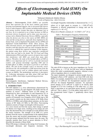
- 1. International Journal of General Science and Engineering Research (IJGSER), ISSN 2455-510X, Vol 4(1), 2019, 47-57 www.ijgser.com 47 Effects of Electromagnetic Field (EMF) On Implantable Medical Devices (IMD) 1 Mohamed Abdultawab Abdulla Albanna Faculty of Engineering - Aden University Abstract: - Electromagnetic Fields (EMFs) are invisible forces that represent one of the most common and fastest growing environmental impacts, due to increased EM sources such as radio frequency (RF) systems including mobile phones and various security systems that play an important role in our lives. So it is expected to see a large increase in EMI on electronic devices in general, and in some cases may pose a serious risk to Medical Electronic Devices (MEDs), especially when the devices are close to the source of EMI. MEDs are vital and life-saving devices, especially those implanted in the human body, such as Implanted Pacemaker devices (IPM) and Implanted Cardio-Defibrillator (ICD). These devices, like other electronic devices, are negatively affected by EMFs that interfere with their function and can cause treatment that does not need or withhold the required treatment. If this happens, the patient using these devices may experience unexpected shocks that can lead to his death. The US Food and Drug Administration (FDA) and other sources of experts have noted that interference with MED can result from many daily sources. Therefore, the study of the harmful effects of EMI on IMDs is very important and we will try to provide interested readers with general knowledge regarding EMI and its harmful effects on IMDs, and means to prevent or curb these effects. The aim of this scientific work is to describe, assess and discuss the risk attributable to EMI interactions from the most common sources such as cellular phones and security systems on IMEDs. The methodology used here is descriptive by: Collecting information and data about EMI and their effects on IMDs, which helps in generalizing protection. Keywords Electromagnetic Interference, Implanted Medical Devices, Mobile Phones, Security Systems. I. INTRODUCTION EM EM radiation is a wave phenomenon characterized by variations of electric (E) and magnetic (H) fields and has all qualities of waves"1 . Different forms of EM energy are categorized by their wavelengths (λ) and frequencies (f), or energy (E). All appliances using electricity are the main sources of Extremely Low Frequency (ELF) fields (up to 300 Hz); security systems are the main sources of IF fields (from 300 Hz to 10 MHz); and cellular phone antennas, are the main sources of RF fields (10 MHz to 300 GHz). Non-ionizing radiation consists of longer wavelengths with less power. 2 As a wave travels out from the source, their energy is spread out thinner over larger areas, resulting in less energy per unit area, thus decreased the wave strength (λ) as the distance from the source increases. The strength of an EMF at a given distance from the source is proportionate to the radiated power from the source and inversely proportionate to the distance. The total energy radiated from the source stays the same. We typically measure their levels as power densities in W/m2 , describes the intensity of these fields. When EM energy is released as the energy level increases, the wavelength decreases and frequency increases. The wavelength frequently relationship is characterized by: , where (c) is light speed in vacuum, (c = 3.00×10⁸ m/s). Frequency is directly proportional to energy and can be express as: Where (h) is Planck's constant, (h = 4.135667 x 10⁻¹⁵ eV.s) Table 1: Wavelength to Frequency Relationship Frequency (f) Wavelength (λ =C/f) 60Hz 5,000 km 100kHz 3 km 1 MHz (AM radio) 300 meters 27MHz (many RF sealers) 11 meters 100MHz (FM radio) 3 meters 300MHz 1 meter 2.45GHz (Microwave ovens) 12.2 cm 10GHz (Satellite data links) 3 cm The ratio (E/H) is known as the wave impedance (η). For air or free space, ηo = 377 Ω. An EM wave with an impedance below this value is predominantly magnetic, whereas a wave with an impedance above it, is mainly electric. The major standards, are designed to protect people from the biological effects of RF radiation—not from EMI with their IMDs. For example, standard has limits in the human resonant region of 1.0 mW/cm² for Occupational exposure and 0.2 mW/cm² for General Population exposure. An equivalent power density of 0.2 mW/cm² is equal to an electric field strength of 27.4 V/m. Looking at it the other way, a 3 V/m field is equivalent to an equivalent power density of 0.0024 mW/cm². This is about 1 % of the public limits and 0.2 % of the occupational limits! Figure 1. graphically shows these levels3 . Fig 1: Plot Showing RF Levels for EMS Concern
- 2. International Journal of General Science and Engineering Research (IJGSER), ISSN 2455-510X, Vol 4(1), 2019, 47-57 www.ijgser.com 48 II. EFFECT OF EMI ON AN ELECTRONIC SYSTEM OR DEVICE EMI occurs when EM waves emitted by one device impede the normal function of another electronic device by injection of the disturbing EM signals inside the targeted device. For radio signals like mobile phone signals any unshielded semiconductor device will tend to act as a detector, which can demodulate the high frequency (HF) mobile phone carrier and produce low-frequency (LF) demodulated noise or sensed signal. Therefore all electronic equipment is susceptible to malfunctions and permanent damage under the EM radiation of sufficient intensity. Therefor; when an EMF induces current(s) and voltage(s) in the circuits of an electronic system, sufficiently intense EM Pulse in the frequency range of (200 MHz to 5 GHz)4 can cause upset (Temporary malfunction) or damage in electronic systems5, 6 . The caused damage is determined by the amount of energy that is transferred while the electronic devices are coupled with EM environment. Maxwell's equations provide a complete description of the interactions among charges, currents, electric fields, and magnetic fields. All the properties of the fields can be obtained by mathematical manipulations of those equations. Voltage is defined as the sum (integral) of the Electric Field across a path (E-field is equal to the rate of change of the voltage with respect to distance). ∫ Faraday's Law, is one of Maxwell's equations, ―the induced EMF in a circuit is equal to the rate of change of magnetic flux linkage through the circuit‖. ∮ ⃗ ⃗⃗⃗⃗ ∫ ⃗ ⃗⃗⃗⃗⃗ (1) The first term is integrated round a closed line, and gives the total voltage change around the circuit, which is generated by a varying magnetic field threading through the circuit. The equation tell us that if we were to define a closed path in any arbitrary location and sum the product of the electric field (E) and length around the loop (ds), the total voltage obtained (Vind) would be equal to the time-rate-of-change (d/dt) of the magnetic flux (B) passing through that closed path (dA), no matter how or where we define the path. If the circuit doesn't move and magnetic flux density is constant (i.e. there are no time-varying quantities), The total magnetic flux (Ψ) passing through the loop within a circuit, is simply the integral of the flux density B over the circuit loop area, ∮ ⃗ ⃗⃗⃗⃗⃗ (2) Faraday figured out that a changing Magnetic Flux within a circuit (or closed loop of wire) produced an induced EMF, or voltage within the circuit. He wrote this as: ∑voltages dropped across components in the loop (3) EMF is the electro-motive force, which is basically a voltage source. Equation [3] says that the induced voltage in a circuit is the opposite of the time-rate-of-change of the magnetic flux. It is known as Lenz's Law (a magnetic field within a loop gives rise to an electric current). III. EFFECT OF EMI ON IMPLANTABLE MEDICAL DEVICES (IMD) Cardiac Implantable Medical Devices (CIMDs) are electronic devices implanted within the human body to treat a medical condition, improve the functioning of some body part, or providing the patient with a capability that he did not possess before7 . Implantable pacemaker These include devices such as Implantable Cardioverter Defibrillators (ICD) and Pacemakers (IPM). They are designed to treat cardiac conditions by monitoring the heart‘s electrical activity and applying electrical impulses (stimulus) of suitable intensity and location in order to make the heart pump at the desired speed8 . These devices are often implanted around 2–3 cm under the patient‘s skin and connected to the organ that needs treatment or monitoring. Cardiac Implants are known to be susceptible to strong EMFs9 . Malfunction of an implant can disable or reprogram therapies, and even inducing a shock state to the patient10 , and may lead to death. The frequency of the EMI determines the efficiency of energy coupling to the device and the resulting effect. The signal may be modulated in amplitude or frequency, and it may occur in bursts or single, long pulses. An RF carrier with amplitude modulation may induce voltages in the signal processing and detection circuitry of a IMD that can be misinterpreted as intra-cardiac signals. In other words, if the amplitude modulation has frequency components in the device‘s physiologic pass band, significant interference occurs. The effects of EMI on cardiac implants depend on the intensity of the EMF, the frequency spectrum of the signal, the distance and positioning (angle) of the device relative to the source, the electrode configuration (unipolar or bipolar), nonprogrammable device characteristics, programmed settings, and patient characteristics. The effects include: a- Static Electric Field do not enter the body; thus, pose no risk for electronic implants. b- Static Magnetic Field penetrate the body and implanted device, potentially activating a reed switch or hall sensor that may trigger the magnet mode "Some pacemakers and ICDs contain a magnetic reed switch that is closed by a static magnetic field". A strong magnetic field can activate the magnet response of a device, which in most cases results in asynchronous pacing for pacemakers and disabling of tachycardia therapy in ICDs. In IMDs that have been programmed to ―mode switch,‖ the pacing mode will change to a mode that inhibits pacing in response to sensed activity or
- 3. International Journal of General Science and Engineering Research (IJGSER), ISSN 2455-510X, Vol 4(1), 2019, 47-57 www.ijgser.com 49 to the ―power-on reset‖ mode, if a large amount of EMI is identified by the device. Normal function returns as soon as the magnetic field dissipates11 . c- Low-Frequency (LF) Field induce electric currents within the human body and the leads of the CIMD. The induced electric current superimposes intrinsic bio-signals that might result in missensing by the device. Depending on the strength and frequency, this may result in a critical local increase in the current density. LF magnetic fields of up to 10 kHz can enter the can of the implant and induce a voltage directly in its electric circuit, leading to malfunction or even damage of the electronic components. d- RF Field with RF exposure, the lead acts as an antenna in which EMFs induce a voltage and, thus, disturb the sensing capabilities of the device. The interference of the sensing capability depends on the device setting, lead configuration and position, as well as physical body characteristics. The problem with IMD interference has grown far more complicated for two reasons: The tremendous growth in the sources of RF energy, and the Microminiaturization resulting in smaller devices requiring less power. Thus the instrument's physical circuit dimensions, electrical characteristics, and shielding all influence the frequency dependency of an instrument's EMS performance. Therefore, EMS has not been a significant problem with older instruments, which operated at high enough power levels to neglect the effects of external fields. To achieve light weight device, modern IMDs are now smaller, and become more susceptible to interference from external sources. As the strength of the interfering field increases and the power level of the instrument's circuitry decreases, the probability of unwanted responses increases significantly. As an example, the LF voltages that could be induced in the Implantable pacemaker's leads and inside the case of the IPM are obey Faraday's Law described by equation 1. When an IPM device with a unipolar lead is exposed to magnetic flux density (B), a voltage (Vind) is induced in the gap between the case and the distal tip of the lead. For IPM with bipolar leads, a much smaller voltage is induced than for IPM with unipolar leads12 . For variously interfering pulsed waves (PW) fields, under particular and rare conditions, the complete inhibition occurred (most dangerous effect for IPM wearer). High levels of interfering continuous waves (CW) field, only in unipolar mode, produce a behavior called ―asynchronous mode‖ (not dangerous)13 . Some instruments show degraded performance when exposed to EMF strengths as low as 0.01 mW/cm2 . This is because some EMI effects occur for field values below the limits suggested by international organizations14 . International standards have been developed establishing the upper limit of permissible field intensities15 . Draft recommendations are available for guidance in the use of wireless technology.16 Also, in the United States, the Center for Devices and Radiological Health of the Food and Drug Administration (FDA) maintains a database of reported incidents of deleterious interactions (MAUDE) that is searchable online.17 Current guidelines18 provide important information on the management of patients with CIEDs. a- For external medical electrical equipment and systems, the main EMC standard utilized is IEC 60601-1-2. In 2014 the fourth edition become mandatory for new device submittals in the US and for all devices sold to the European Union. The fourth edition is a based solely on the safety of the medical device and addresses interference from nearby mobile transmitting devices and other environments. To address the efficacy concerns, IEC TR 60601-4-2 was published in 2016. b- For many active implantable devices the EMC requirements are contained in ISO 14708. That standard has multiple parts. ISO 14708-3 (implantable neuro-stimulators) is scheduled to be revised in 2017. c- The Medical Devices Directive (MDD) focuses on the safety and essential performance, and the Radio Equipment Directive (2014/53/EU) focuses only on the performance (functionality), both these directives require the EM disturbances to be measured and an assessment of the product‘s EM performance made. 3.1 EMI with IMD from mobile phone signals Interference by electrical appliances generating 50-or 60- Hz electrical or magnetic fields in close or direct contact with cardiac pacemakers is a known potential hazard19 . Over the past several years there has been also concern that signals from some RF devices could interfere with the operation of medical devices. The use of mobile phones is prohibited in hospitals in many countries, due to the possible risks of EMF emitted by mobile phones interfering with medical devices. There were a number of incidences reported in the past,20, 21 which showed the risks of using mobile devices in proximity to certain types of medical devices. Therefore; the mobile phone is potentially the greatest source of exposure to RF radiation, in terms of intensity, especially during the pre- ringing and ringing phase. The power level used by a wireless telephone fluctuates throughout the call, according to distance from the base station and the number of devices being used on the system at the same time. Several studies have shown that cellular phones might cause EMI with complex medical equipment22, 23 including pacemakers.24, 25 Mobile phones are more likely to cause interference in the atrial channel due to the small intrinsic atrial signal and a corresponding poor signal-to-noise ratio.26 An in vivo study of IPM patients showed that clinically significant interference only occurred when cellular phones were directly held over the IPM.27 For data transmission a pulse amplitude modulation of 50 pulses/s is used (TDMA-50) and the peak power of the handset is limited to 0.6 W. In contrast, the peak power of digital phones GSM D-net is 2 W and 1 W for GSM E-net28, 29 . The D-net works on a carrier frequency of 900 MHz modulated with 217 Hz; the E-net works on a carrier frequency of 1800 MHz. Most interferences were seen when the GSM-phones were in a short distance to the ICDs.30 The pulsed component of the transmission in digital cell phones was detectable by pacemaker sensing circuitry if the field was strong enough. Almost all interactions occurred at distances of less than 10 cm. Devices always reverted to normal operation when the phone was turned off. Table 2: Summary of the ICNIRP EMF exposure guidelines31 Mobile phone base station frequency Frequency 900 MHz 1.8 GHz Power density (W/m2 ) Public exposure limits 4.5 9
- 4. International Journal of General Science and Engineering Research (IJGSER), ISSN 2455-510X, Vol 4(1), 2019, 47-57 www.ijgser.com 50 Occupational exposure limits 22.5 45 As the distance between an RF transmitting device and susceptible electronic device decreases, the likelihood of interference increases. Also, the higher the power of an RF transmitter, the more likely interference is to occur. Low- power transmitters can create strong EMFs at close range. Several investigators reported EMI effects on IMDs, due to over-sensing of emitted electrical signals from the cell phone.32 More EMI was observed with cell phones using (900 MHz, 1800 MHz, 2100 MHz) technology because of the higher powers and continuous pulsing associated with digital signals.33 Table 3: IEC EM Environments classification34 Classification Signal Strength Residential: Rural up to 3 V/m Residential: Urban up to 10 V/m Light Industrial up to 3 V/m Dedicated Communications Center up to 1 V/m Hospital up to 3 V/m The exposure to EM waves outgoing from mobile phone device takes the form of duplicate short pulses with high energy in a very short period of time about 546 µs of each pulse. The field strength emitted by the phones ranged from 10.18 mW to 243.82 mW. The radiation limits in Part 15.231 of the FCC Regulations are expressed as field strength (V/m) at a distance of 3 meters from the transmitter. The FCC sets the field-strength limit at 3750 µV/m at 260 MHz, and allows a linear increase to 12500 µV/m at 470 MHz. Several studies have shown that mobile phones signals can interfere with the functioning of MEDs: a- In 2003, a study by the Committee for the Evaluation and Dissemination of Technological Innovations (CEDIT) indicated that the interference caused by the use of mobile phones would not affect medical devices if they were morethan 1.5 m away and was not hazardous for people with active implanted medical devices, on condition that certain precautions be taken. b- The Directorate General for Health and the Directorate General for Risk Prevention formally requested (ANSES) to issue an opinion on the potential risks of EMI with medical devices exposed to RF radiation and propose, if appropriate, minimum safety distances to be respected according to the different sensitivities of medical devices. c- The Therapeutic Goods Administration of Australia (TGA) continues to review findings of clinical and laboratory re- search indicating a potential for temporary interaction or interference between mobile phones and the operation of pacemakers and implantable defibrillators. The findings have indicated that interference may be caused by holding the phone within about 150 mm of the implanted device, or in direct contact between the phone antenna and the user‘s skin. Interference can occur with the phone in standby mode, as well as in use.35 d- According to their observations, both The Health Protection Branch of Health Canada and clinical researchers (The Center for the Study of Wireless Electromagnetic Compatibility at the University of Oklahoma, and the U.S. Food and Drug Administration's Center for Devices and Radiological Health (FDA-CDRH)) have noted that interactions: a) Do not occur in all brands and models of pacemakers, b) Occur only with the use of telephones operating in the digital mode, and c) Are observed only when the telephone's transmitting antenna is within a few centimeters (i.e., < 6 cm for implanted pacemakers) and directly over the site of implantation of the pacemaker unit. The recommendation of Health Canada and the pacemaker industry that patients should hold the phone to the ear farthest from the pacemaker and avoid carrying it in a breast pocket directly over the implanted device36 . EMF guidelines do not protect against potential interference with MEDs. The Agency recommends that wearers of active IMDs ensure that they keep their devices away from the greatest sources of exposure (mobile phones or security systems). The distances to be respected if mobile phones are used or when passing through security gates. Avoiding physical proximity between the IMD and the cell phone such as that which occurs when keeping the phone in a breast pocket near the IMED.37 The Guidelines to Safeguard IMEDs against emissions from mobile phone handsets, states that: "People with IMED should keep mobile phone handsets at least 22 cm away from the IMD"38, 39 . A person with an implanted pacemaker should use or carry a mobile telephone terminal at a distances more than 22 cm from the site of implantation".40 Table 4: Limits for Maximum Permissible Exposure (MPE) - from §1.131041 Frequency Range (MHz) Electric Field Strength (V/m) Magnetic Field Strength (A/m) Power Density (mW/cm2 ) Averaging Time (minutes) 0.3-3.0 614 1.63 100 † 6 3.0-30 1842/f 4.89/f 900/f2 † 6 30-300 61.4 0.163 1.0 6 300-1500 - - f/300 6 1500-100,000 - - 5 6 Limits for General Population/Uncontrolled Exposure 0.3-3.0 614 1.63 100 † 30 3.0-30 842/f 2.19/f 180/f2 † 30
- 5. International Journal of General Science and Engineering Research (IJGSER), ISSN 2455-510X, Vol 4(1), 2019, 47-57 www.ijgser.com 51 30-300 27.5 0.073 0.2 30 300-1500 - - f/1500 30 1500-100,000 - - 1.0 30 f = frequency in MHz.† = plane-wave equivalent power density. Equivalent far field density for near and far fields can be calculated using Power Density = |Etotal|2 /3770 mW/cm2 or Power Density = |Htotal|2 /37.7 mW/cm2 . 3.2 EMI with IMD from Electronic Security Systems (ESS) There are three different sorts of ESSs: 1- Electronic Article Surveillance (EAS) devices, 2- Airport screening (Walk-through), and handheld metal-detector(MDS) Systems, and 3- Radio Frequency Identification (RFID) devices. Common to all is the production of magnetic fields. Interactions between such systems and active implanted medical devices (AIMD) occur and are common in patients with pacemakers and implantable defibrillators. Exogenous signals of similar intensity and rhythm to heart signals can be misinterpreted and, thus, confuse the implant. There have been specific concerns involving these medical devices being potentially vulnerable to EMI in proximity to security systems42 . The reason for this is because there is a small magnetically activated switch built into the electronics of pacemakers and implantable defibrillators. This internal switch is designed to close when a magnet of enough strength is placed over it. When the internal switch is closed in the pacemaker, the pacemaker paces the heart at a continuous preset rate (which could be different than the rate programmed by doctor). When the internal switch is closed in an implantable defibrillator, it prevents it from delivering treatment therapies. Removing the magnet returns the pacemaker or implantable defibrillator to its previous, normal programming. A recent search of reports in the FDA‘s manufacturer and user facility device experience (MAUDE) database reveals there were more than 350 incident reports between 2014 and 2016 for certain active medical devices that appear to be related to security systems43 . From such evidence there appears to be continuing issues involving EMI via exposure of active IMDs, with ESS. FDA also recognized the issues associated with security systems and provided recommendations for patients with implantable medical devices44 . 3.2.1 EMI with IMD from EAS devices Electronic surveillance systems operate in a wide range of frequencies from 20 Hz to 2.5 GHz and use different technologies include high-frequency systems (operating beyond 900 MHz), magnetic audio frequency, swept RF frequency (operating at 2 MHz to 10 MHz), acousto- magnetic or pulsed low-frequency (30 kHz - 132 kHz), and EM systems (20 Hz to 18 kHz). The transmitter in these devices emits an EMF that is designed to interact with passive or active tags on objects. As a result of the interaction, the tag emits a signal that is detected by the receiver. Customers are exposed to an EMF as they walk through the gate, which typically consists of a pair of transmitter and receiver pedestals. EMI with permanent pacemakers and implantable defibrillators may have deleterious effects.45 Interference from EAS device poses several risks for patients with defibrillators, including the induction of ventricular arrhythmias as a result of inappropriate pauses or shocks, injury from falling, and the physical discomfort and psychological effects of multiple shocks. The defibrillator could exhaust its programmed therapies and be unable to convert a true tachyarrhythmia to normal rhythm. The maximum distance at which ventricular over-sensing occurred was 30 cm. The potential for harmful EMI by EAS systems on implantable pacemakers and defibrillators has already been recognized.46, 47, 48 The interaction between implantable devices and EAS systems is a serious problem, and has been well documented.49, 50 Case reports have been published in which patients received inappropriate ICD therapies while lingering between or touching EAS gates. There have been also sporadic reports of adverse CIED interactions (inappropriate shocks) with security systems in the retail environment51, 52 Reports of such interactions are probably due to potentially longer exposure to EMI sources.53 However, EMI that could lead to inappropriate therapy was observed during prolonged exposure (2 minutes) with the ICD positioned within 6 inches of the gate.54 The literature suggests, that significant EMI with IMDs devices is most likely to occur with prolonged, close exposure to acousto-magnetic mode of EAS, and that pacemakers are more likely to be affected than ICDs. More prolonged exposures or closer proximity to the transmitter can result in inappropriate shocks. These effects on pacemakers occur only while the patient is within the EAS device's magnetic field. To minimize the risk of temporary interference with IMD while going through the security system, the Published guidelines advise patients to walk normally, and not slowly, through EAS systems, and to avoid both lingering within the EAS gates and direct contact with the gates.55 Unanticipated, inadvertent, prolonged exposure to an EAS system by a customer with an implantable device may create a medical emergency56 . The Guidelines to Safeguard implanted medical devices against emissions from EAS equipment, states that:57, 58 a) Where EAS equipment is installed or where an EAS sticker is posted, People with an IMD should walk in the middle of the pathway without stopping. b) People with an IMD should not stay near or lean on EAS equipment. c) People wearing a cardiac pacemaker should keep pacemaker at least 12 cm away from the read/write (antenna) of the wireless card system. 3.2.2 EMI with IMD from Airport Screening and handheld MDS Handheld and walk-through metal detectors are used for security applications. Airport screening (Walk-through),
- 6. International Journal of General Science and Engineering Research (IJGSER), ISSN 2455-510X, Vol 4(1), 2019, 47-57 www.ijgser.com 52 and handheld metal-detector security Systems detects disturbance of the emitted low frequency (LF) magnetic field. Walk-through metal detectors use either continuous 5 – 10 kHz or pulsed 200 – 400 Hz wave modes, providing considerably higher magnetic-field strengths compared with handheld detectors, which operate in 80 – 130 KHz continuous-wave mode.59 Handheld metal detectors typically produce weak fields (≤ 4 A/m at a distance of 1 inch), a person walking through is exposed for 3 seconds. The effect of metal-detector gates on IPMs has been studied more than 10 years ago60 . In normal operation these security systems typically involve short exposure times61 to the emissions from the system, but can have a range of exposure amplitudes depending on the orientation and location near the emitters62 . As Tiikkaja et al.63, 64 noted, the exposure waveform is an important parameter in assessing EMC with active IMDs. At the lower frequency range, this security system typically use near-field magnetic fields where these fields dominate the concerns for interference for the active medical devices. It may be possible, under unique circumstances, for these fields to temporarily affect the operation of heart device65 . The far field begins approximately at a distance beyond r = meters. For example, one wavelength is 30 cm at 1 GHz. Therefore, the far field begins at about 30/6.28 = 4.78 cm from the source and beyond. Inside that range is the near field, which consists mainly of a predominant magnetic or electric field. Current FDA recommendations state that it is safe for patients with implanted cardiac devices to walk through a metal detector gate, although the alarm may be triggered by the generator case. If scanning with a handheld metal detector is needed, the security personnel must not hold the detector close to the implanted device longer than is absolutely necessary. 3.2.3 EMI with IMD from RFID RFID induced potentially hazardous incidents in medical devices. This system use radio waves at several different frequencies to transfer data. It refers to a wireless system comprised of two components: readers and tags. The reader is a device that has one or more antennas that emit radio waves and receive signals back from the RFID tag. Tags, which use radio waves to communicate their identity and other possible information to nearby readers. The RFID tags contain a wire coil as well as a capacitor and inductor which enables the tag to store energy until it reaches the frequency needed for transmission. The RFID reader or transmitter sends out RF waves and the RFID tags receive the energy and quickly pass it back and forth down the coil in order to build up enough energy to respond. A wideband receiver receives the response when the tag is in between or extremely close to the pedestals. The number of coils and size of the RFID tag determine the available read distance between the tag and pedestals, which is usually a few feet. They are manufactured as either: a) Passive RFID tags (do not have internal power), are activated by the EMF generated by the reader, and transmit information back to the reader. The EMF can cover a distance ranging from 1 to 50 cm to 10 to 30 m. b) Active RFID tags (operated by batteries) can broadcast information, such as identity or product temperature, without being activated by the reader.66 It can broadcast over a distance of 50 to 100 m. The EM radiation from RFID tags and its readers may cause interference to the effective functioning of the medical devices. The nature of interference caused depends on tag type, the distance between reader and medical device, the operating frequency and maximum power emission by the reader. A Dutch study on RFID tags and medical equipment published in the Journal of the American Medical Association (JAMA) indicated that: "the radio frequency emissions from these tags could have unintended and dangerous consequences by interfering with vital medical devices. The median distance between reader and device at which all types of RFID incidents occurred was 30 cm with a considerable range up to 600 cm. Hazardous incidents occurred at a median distance of 25 cm with a range from 5 cm to 400 cm. Incidents occurred at greater distances with the 868-MHz passive RFID signal compared with the 125-kHz active RFID signal. The low- frequency RFID technique (e.g. 134 kHz) may be of potential risk for IPM and ICDs device patients.67 The number of EMI incidents increased with higher output power of transmitting RFID systems; similar to mobile phone technology.68 In a controlled nonclinical trial setting, RFID technology is capable of inducing potentially hazardous incidents in medical devices69 . The FDA is not aware of any adverse events associated with RFID. However, there is concern about the potential hazard of EMI to EMDs from RF transmitters like RFID. The Guidelines to Safeguard implanted medical devices against emissions from RFID (electronic tag) equipment, states that:70, 71 : (1) Gate-Type RFID equipment a) where Gate-Type RFID equipment is installed or where an RFID sticker is posted, People with IMD should walk in the middle of the pathway without stopping. b) People with IMD should not stay near or lean on Gate- Type RFID equipment. (2) Handheld-type, Stationary-type, and Modular-type RFID equipment a) the operator of handheld-type RFID equipment should keep the antenna of the equipment at least 22 cm away from the IMD. b) People with IMD should keep the IMD at least 22 cm away from the antenna Stationary-type, and Modular-type RFID equipment. c) where Stationary-type RFID equipment (950 MHz high power passive tag system) is installed or where an RFID sticker is posted, People with an IMD should keep 1 m away. d) people wearing a cardiac pacemaker should keep pacemaker at least 12 cm away from the read/write (antenna) of the wireless card system.
- 7. International Journal of General Science and Engineering Research (IJGSER), ISSN 2455-510X, Vol 4(1), 2019, 47-57 www.ijgser.com 53 Table 5 Effects of Security Systems on Implantable Cardiac Pacemakers72 Type Mode Carrier Frequency Magnetic Field Strength (µT) * Effects on Pacemakers Inhibition Re-activation EAS Continuous 535 Hz 450 23 % 55 % Modulated Pulse carrier: 58.4 KHz modulation: 60 Hz 400 36 % 68 % Sweep 7.4 - 9.1 MHz 0.1 0 % 0 % WTMD Pulse 250 - 500 Hz 4.5 - 10 5 % 9 % Pulse 89 Hz 45 36 % 64 % Modulated Pulse 250 - 909 Hz 18 - 22 5 % 9 % Modulated Pulse 210 Hz 12 9 % 14 % HHMD Continuous 14 kHz - 1.8 MHz 0.2 - 10 0 % 0 % * Measured at 15 cm from the transmission panel of EAS and WTMD systems, and 2.5 cm from HHMDs; 0 % indicates no interference effects IV. CONCLUSIONS: PRECAUTIONS AND RECOMMENDATIONS: Exposure to the EM environment, frequency, location, direction and design of a IMD can indicate whether the device will be affected by EMI and how it is affected. In any case, it is virtually impossible to completely stop EM energy at its source. Also it is difficult to make medical devices immune to all sources of EMI, so it is difficult to prevent all the faults caused by EMI, but many of these failures, can be avoided by educating users, manufacturer, and regulatory agency on EMI and to develop a specific standards for medical electronic equipment and systems. Digital cell phones and security systems can potentially interfere with IMDs. The interference effects ceased when the phones were turned off and the pacemakers reverted to their normal operations. Interference effects were generally not observed when the cell phone was more than 15 cm from the pacemaker. The EMI generated by the wireless devices did not reprogram or damage the pacemakers. Pacemaker patients should not stop within 33 cm of either side of the transmission panel of ESS. This paper provide a scientific review of some sources of EMI, their interaction with IMDs, and the result of researches conducted on mobile phone, and ESS. It investigate the effects of EMI signal caused by ESS and mobile phone devices that may occur on IMDs. Due to the increased use of both IMD, and (ESS systems and Digital cell phones), and to avoid potentially dangerous interactions between them in the future, precautions and protections should be taken. A- The most important precautions to patients with IMD are: 1. The treating physician be aware of the potential sources of EMI to which each particular patient is likely to be exposed and must choose the type of device and specify site of implant accordingly. 2. The patient should avoid prolonged exposure to ESS systems, not lingering within their gates or contact the gates directly or lean on the gates. 3. The patient should maintain a greater distance (usually > 30 cm) to the source of EMFs73 . B- The most important precautions for ESS systems owner are: 1. Avoid placing ESS systems in the waiting or resting areas (for example: near the checkout counters). 2. Avoid displaying merchandise in the spread area of ESS's signals. C. The most important protection points proposed by IMD designers are: 1. active cardiac implants must be immune to interference from very high intensity magnetic field strengths74 . 2. True bipolar leads have a better signal-to-noise ratio and a smaller ‗functional antenna‘ to capture EMFs and should be implanted in all patients if possible75 . 3. Low pass filters with bipolar sensing pacemaker device reduces conducted and radiated interference. However, in unipolar sensing/pacing functions this conductor may act as an antenna that carries EMI. 4. Feed-through capacitor filters (used to carry a signal through the pacemaker casing) are integrated in the device header (lead connector) acting as low-pass filter, to prevent EMI from a wide range of frequencies including mobile phone frequencies76 , thus attenuating HF noise signals strongly, and preventing conduction of RF carrier signals from mobile phones into the pacemaker circuitry. 5. The neural amplifier bringing improvements in bio- potential amplifier design, their circuit performance and scalability. Neural Amplifier ICs will enable fully implantable interfaces, enabling closed-loop neuro- modulation therapies77 .
- 8. International Journal of General Science and Engineering Research (IJGSER), ISSN 2455-510X, Vol 4(1), 2019, 47-57 www.ijgser.com 54 V. DEFINITION AND TERMS: 1- Interference: The ability of waves to combine with other waves. There are: a) Constructive interference occurs when two or more waves are in phase and their displacements add to produce a higher amplitude. b) Destructive interference occurs when two or more waves are out of phase and their displacements negate each other to produce lower amplitude. International Telecommunication Union's (ITU) definition: Interference with the meaning of EMI is –– defined as «The effect of unwanted energy due to one or a combination of emissions, radiations, or inductions upon reception in a radio-communication system, manifested by any performance degradation, misinterpretation, or loss of information which could be extracted in the absence of such unwanted energy»78 . It can cause erroneous data, unwanted results, false alarms, or even complete shutdown of the instrument. The effects can be totally unpredictable. Instruments showing no effect from signals at one frequency may behave totally different at another. 2- Electromagnetic interference (EMI): General term used for electrical signals that interfere with the normal operation of electronic equipment. It can degrade the performance of the equipment, introduce errors or operational faults, or even stop it from functioning. The US Food and Drug Administration's definition of EMI: ―degradation of the performance of a piece of equipment, transmission channel, or system (such as medical devices) caused by an electromagnetic disturbance.‖79 It may be: a) Self-generated, where one circuit interferes with another inside the equipment, or b) Externally generated by some other device or equipment within the same environment. EMI can occur as a result of conducted or radiated EM energy. a) Conducted: noise or interference that‘s passed over wires and cables or power lines (lower frequencies) from a source or emitter to the receiver or ―victim‖ device. b) Radiated: when EM energy is emitted from a source, propagates to the far-field region (when the source and victim circuits are separated by many wavelengths), and induces voltages and currents in another circuit. Unlike electric and magnetic field coupling, the victim circuit is not in the EM near field region of the source. The far field is the region in which the field acts as "normal" EM radiation. In this region, it is dominated by electric or magnetic fields with electric dipole characteristics. In this region the intensity of an EMF can be described in terms of the E field, H field or PD, they are all equivalent and related by the following equations80 : and , or Where ηo is the characteristic impedance of vacuum that is ηo = 120π Ω ≈ 377 Ω. Since power is the rate of energy transfer, and the squares of E and H are proportional to power, E2 and H2 are proportional to the energy transfer rate and the energy absorbed by the subject. EMI can categorize as either: a) Broadband EMI is unintentional radiation from sources such as electric power transmission lines.81 A broadband source produces a wide swath of harmonics. b) Narrowband EMI usually comes from a single sine wave source or one that‘s modulated over a limited channel, such as cell phones, and other radios. 3- EM compatibility (EMC): It is defined as adequate device function in an accepted EM environment without interference with other devices. It describes efforts to minimize the possibility of EMI. These efforts include shielding, which includes protecting the MEDs generator and/or lead circuitry with EMF barriers composed of conductive or magnetic materials. 4- EM susceptibility (EMS): A circuit's susceptibility to interfering radio waves is referred to as its EMS. 5- Medical Electronic Devices (MED) are electronic devices either implanted in the human body such as Pacemakers or worn on the body with some type of delivery system. REFERENCES: [1] ANSI/IEEE 100-1984, IEEE Standard Dictionary of Electrical and Electronics Terms, 1984, page 305. [2] Roy Beinart, and Saman Nazarian, Effects of External Electrical and Magnetic Fields on Pacemakers and Defibrillators: From Engineering Principles to Clinical Practice, NIHMS543016, 2013 Dec 24; 128(25): 2799–2809. [3] Electromagnetic Radiation and how it affects our instruments-may 20, 1990-OSHA Cincinnati Laboratory [4] This range is extensively populated with the radars, television broadcasting, mobile communications, high power microwave (HPM) sources, etc. [5] X. Fei, C. Bing and L. Chenglong, ―Damage efficiency research of PCB components under strong electromagnetic pulse‖ Applied Mechanics and Materials, vol. 130-134, pp. 1383-1386, 2012. [6] Vladimir Vasilevich Shurenkov, Vyacheslav Sergeevich Pershenkov - Electromagnetic Pulse Effects And Damage Mechanism On The Semiconductor Electronics – FACTA UNIVERSITATIS Series: Electronics and Energetic Vol. 29, N0 4, December 2016, pp. 621 – 629 [7] J.A. Hansen, N.M. HansenA taxonomy of vulnerabilities in implantable medical devices, Proc. of the Second Annual Workshop on Security and Privacy in Medical and Home-care Systems, SPIMACS ‘10, ACM, New York, USA (2010), pp. 13-20 [8] - J.G. WebsterDesign of Cardiac Pacemakers, IEEE Press (1995) [9] - Napp A, Joosten S, Stunder D, Knackstedt C, Zink M, Bellmann B, Marx N, Schauerte P, Silny J. Electromagnetic interference with implantable cardioverterdefibrillators at power frequency:an in vivo study. Circulation 2014;129:441– 450. [10] - D. Halperin, T.S. Heydt-Benjamin, B. Ransford, S.S. Clark, B. Defend, W. Morgan, K. Fu, T. Kohno, W.H. Maisel, Pacemakers and implantable cardiac defibrillators: software radio attacks and zero-power defenses, in: Proc. of the 29th Annual IEEE Symposium on Security and Privacy, 2008, pp. 129–142.
- 9. International Journal of General Science and Engineering Research (IJGSER), ISSN 2455-510X, Vol 4(1), 2019, 47-57 www.ijgser.com 55 [11] Juna Misiri, Fred Kusumoto, Nora Goldschlager. Review: Electromagnetic Interference and Implanted Cardiac Devices: The Nonmedical Environment (Part I), 2012 [11] Howard Bassen; Low frequency magnetic emissions and resulting induced voltages in a pacemaker by iPod portable music players - BioMedical Engineering OnLine. [13] Giuseppe Della Chiara, Valter Mariani Primiani and Franco Moglie; Experimental and numeric investigation about electromagnetic interference between implantable cardiac pacemaker and magnetic fields at power line frequency - Ann Ist super sAnItà 2007 | Vol. 43, no. 3: 248-253 [14] Cooper TG. Occupational exposure to electric and magnetic fields in the context of the ICNIRP guidelines. Chilton,Didcot, UK: National Radiological Protection Board;September 2002. (Tech. Rep NRPB-24).253 [15] Active implantable medical devices - Electromagnetic compatibility - EMC test protocols for implantable cardiac pacemakers, implantable cardioverter defibrillators. ANSI/AAMI PC69:2007. Washington, DC: ANSI. 2007. [16] Radio Frequency Wireless Technology in Medical Devices, FDA Industry Guidance, 2013. [17] Center for devices and radiological health. Medical device reporting. Available at: http://www.fda.gov/cdrh/maude.html. Accessed August 2, 2001. [18] Crossley GH, Poole JE, Rozner MA, Asirvatham SJ, Cheng A, Chung MK, Ferguson TB Jr, Gallagher JD, Gold MR, Hoyt RH, Irefin S, Kusumoto FM, Moorman LP, Thompson A. The Heart Rhythm Society/American Society of Anesthesiologists resynchronization therapy: the Task Force on cardiac pacing and resynchronization therapy of the European Society of Cardiology. Developed in collaboration with the European Heart Rhythm Association. Eur Heart J 2013;34:2281–2329. [19] S.L. Pinski, R.G. TrohmanInterference in implanted cardiac devices: part I Pacing Clin Electrophysiol, 25 (2002), pp. 1367-1381 [20] W. E. Irnich, R. Tobisch, "Mobile phones in hospitals", Biomed. Instrum. Technol., vol. 33, pp. 28-34, 1999. [21] G. Calcagnini, P. Bartolini, M. Floris, M. Triventi, P. Cianfanelli, G. Scavino, L. Proietti, V. Barbaro, "Electromagnetic interference to infusion pumps from GSM mobile phones", Proc. 26th Annu. Int. Conf. IEEE EMBS, vol. 2, pp. 3515-3518, 2004-Sep. [22] Naegeli B, Deola M, Eicher B, et al. Pacemaker dysfunction caused by interference with Natel-D mobile phones (Abstr.) Pacing Clin Electrophysiol. 1995;18:842. [23] Irnich W, Batz L, Muller R, et al. Electromagnetic interferences of pacemaker by mobile phones. Pacing Clin Electrophysiol. 1996;19:1431–1446. [24] Naegeli B, Osswald S, Deola M, et al. Intermittent pacemaker dysfunction caused by digital mobile telephones. J Am Coll Cardiol. 1996;27:1471–1477. [25] Barbaro V, Bartolini P, Donato A, et al. Do European GSM mobile cellular phones pose a potential risk to pacemaker patients? Pacing Clin Electrophysiol. 1995;18:1218–1224. [26] IrnichW, Batz L, Muller R, Tobisch R. EMI of pacemakers by mobile phones. Pacing Clin Electrophysiol 1996;19:1431–1446. [27] Hayes DL,Wang PJ, Reynolds DW, Estes M 3rd, Griffith JL, Steffens RA, Carlo GL, Findlay GK, Johnson CM. Interference with cardiac pacemakers by cellular telephones. N Engl J Med 1997;336:1473–1479. [28] Hayes DL, Carillo RG, Findly GK, et al. State of the science: pacemaker and defibrillator interference from wireless communication devices. Pacing Clin Electrophysiol. 1996;19:1419–1430. [29] Niehaus M, Gille K, Cierpka R, et al. Interference of two common European digital cellular phones with implantable cardioverter-defibrillators. Eur Heart J. 2002;23:586–588. [30] Bonney CH, Rustan PL, Fond GE, et al. Evaluation of effects of microwaves oven (915 and 23450 MHz) and radar (2810 and 3050 MHz) electromagnetic radiation on noncompetetive cardiac pacemakers. IEEE Trans Biomed Eng. 1973;20:357–364. [31] ICNIRP, EMF guidelines, Health Physics 74, 494-522 (1998) [32] Barbaro V, Bartolini P, Donato A, et al. Electromagnetic interference of analog cellular telephones with pacemakers. Pacing Clin Electrophysiol. 1996;19:1410–1418. [33] Irnich W, Batz L, Müller R, et al. Electromagnetic interference of pacemakers by mobile phones. Pacing Clin Electrophysiol. 1996;19:1431–1446. [34] The International Electro-technical Commission (IEC). An electric field strength of 3 V/m is often referenced because it is the most common standard that is cited for medical device immunity. The relatively low-power cellular telephone can create a field strength of 3 V/m at one meter. [35] Compliance Engineering‘s European edition Jan/ Feb 1998 [36] Alert Letter No.108: ―Digital cellular phone interference with cardiac pacemakers‖, Health Canada, Ottawa, Canada, November 6, 1995. [37] Cohan L, Kusumoto FM, Goldschlager NF. Environmental effects on cardiac pacing systems. In: Kusumoto FM, Goldschlager NF, eds. Cardiac Pacing for the Clinician. New York, NY: Springer; 2008;595–618. [38] "Guidelines on the Use of Radio communications Equipment such as Cellular Telephones and Safeguards for Implanted Medical Devices" (enacted in August 2005, are revised in April 2007). [39] "Guidelines on the Use of Radio communications Equipment such as Cellular Telephones and Safeguards for Electronic Medical Equipment" was enacted in 1997 at the EM Compatibility Conference Japan. [40] The "Guidelines on the Use of Radio communications Equipment such as Cellular Telephones and Safeguards for Electronic Medical Equipment" was enacted in 1997 at the EM Compatibility Conference Japan [41] The Federal Communications Commission (FCC), 2007. [42] Joshua Guag, Bisrat Addissie and Donald Witters; Personal medical electronic devices and walk‑through metal detector security systems: assessing electromagnetic interference effects. [43] Manufacturer and user facility device experience database (MAUDE) [44] U. S. Food and Drug Administration. Important information on anti-theft and metal detector systems and pacemakers, ICDs, and spinal cord stimulators. 1998
- 10. International Journal of General Science and Engineering Research (IJGSER), ISSN 2455-510X, Vol 4(1), 2019, 47-57 www.ijgser.com 56 [45] Lucas EH, Johnson D, McElroy BP. The effects of electronic article surveillance systems on permanent cardiac pacemakers: an in vitro study. Pacing Clin Electrophysiol 1994;17:2021-6. [46] Irnich W. Electronic security systems and active implantable medical devices. Pacing Clin Electrophysiol. 2002;25(8):1235-1258 [47]Santucci PA, Haw J, Trohman RG, Pinski SL. Interference with an implantable defibrillator by an EAS device. N Engl J Med. 1998;339(19):1371-1374 [48] Groh W, Boschee SA, Engelstein ED, et al. Interaction between electronic surveillance systems and implantable cardioverter-defibrillators. Circulation. 1999;100:387–392. [49] Lucas EH, Johnson D, McElroy BP. The effects of electronic article surveillance systems on permanent cardiac pacemakers: an in vitro study. Pacing Clin Electrophysiol 1994;17:2021-6. [50] Hayes DL, Wang PJ, Reynolds DW, et al. Interference with cardiac pacemakers by cellular telephones. N Engl J Med 1997;336:1473-9. [51] McIvor ME, Reddinger J, Floden E, et al. Study of Pacemaker and Implantable Cardioverter Defibrillator Triggering by Electronic Article Surveillance Devices (SPICED TEAS). Pacing Clin Electrophysiol. 1998;21:1847– 1861. [52] Mathew P, Lewis C, Neglia J, et al. Interactions between electronic article surveillance systems and implantable defibrillators: insights from a fourth generation ICD. Pacing Clin Electrophysiol. 1997;20:2857–2859. [53] Gimbel JR, Cox JW Jr. Electronic article surveillance systems and interactions with implantable cardiac devices: risk of adverse interactions in public and commercial spaces. Mayo Clin Proc. 2007;82:318–322. [54] Groh WJ, Boschee SA, Engelstein ED, et al. Interactions between electronic article surveillance systems and implantable cardioverter-defibrillators. Circulation. 1999;100:387–392. [55] Goldschlager N, Epstein A, Friedman P, Gang E, Krol R, Olshansky B, North American Society of Pacing and Electrophysiology (NASPE) Practice Guideline Committee. Environmental and drug effects on patients with pacemakers and implantable cardioverter/defibrillators: a practical guide to patient treatment. Arch Intern Med. 2001;161:649-655. [56] Thomas Wolber, Salome Ryf, Christian Binggeli, Johannes Holzmeister, Corinna Brunckhorst, Roger Luechinger, Firat Duru; Potential interference of small neodymium magnets with cardiac pacemakers and implantable cardioverter-defibrillators. [57] "Guidelines on the Use of Radio communications Equipment such as Cellular Telephones and Safeguards for Implanted Medical Devices" (enacted in August 2005, are revised in April 2007). [58] "Guidelines on the Use of Radio communications Equipment such as Cellular Telephones and Safeguards for Electronic Medical Equipment" was enacted in 1997 at the EM Compatibility Conference Japan. [59] Boivin W, Coletta J, Kerr L. Characterization of the magnetic fields around walk-through and hand-held metal detectors. Health physics. 2003;84:582–593. [60] Copperman Y, Zarfati D, Laniado S. The effect of metal detector gateways on implanted permanent pacemakers. Pacing Clin Electrophysiol. 1988;11:1386–1387. [61] International Commission on Non-Ionizing Radiation Protection ICNIRP statement related to the use of security and similar devices utilizing electromagnetic fields. Health Phys. 2004;87(2):187–196. [62] Personal medical electronic devices and walk‑through metal detector security systems: assessing electromagnetic interference effects - Joshua Guag*, Bisrat Addissie and Donald Witters [63] Tiikkaja M, Alanko T, Lindholm H, Hietanen M, Hartikainen J, Toivonen L. Experimental study on malfunction of pacemakers due to exposure to different external magnetic fields. J Interv Card Electrophysiol. 2012;34(1):19–27. [64] Tiikkaja M, Alanko T, Lindholm H, Hietanen M, Toivonen L, Hartikainen J. Interference of low frequency magnetic fields with implantable cardioverter-defibrillators. Scand Cardiovasc J. 2012;46(5):308–314. [65] Personal medical electronic devices and walk‑through metal detector security systems: assessing electromagnetic interference effects - Joshua Guag*, Bisrat Addissie and Donald Witters [66] Kabachinski J. An introduction to RFID. Biomed Instrum Technol. 2005;39(2):131-134 [67] Seidman SJ, Brockman R, Lewis BM, Guag J, Shein MJ, Clement WJ, Kippola J, Digby D, Barber C, Huntwork D. In vitro tests reveal sample radiofrequency identification readers inducing clinically significant electromagnetic interference to implantable pacemakers and implantable cardioverter- defibrillators. Heart Rhythm 2010;7:99–107. [68] Tan KS, Hinberg I. Effects of a wireless local area network (LAN) system, a telemetry system, and electrosurgical devices on medical devices in a hospital environment. Biomed Instrum Technol. 2000;34(2):115-118 [69] Remko van der Togt; Erik Jan van Lieshout; Reinout Hensbroek; et al E. Beinat; J. M. Binnekade; P. J. M. Bakker - JAMA. 2008;299(24):2884-2890. Electromagnetic Interference From Radio Frequency Identification Inducing Potentially Hazardous Incidents in Critical Care Medical Equipment- June 25, 2008 [70] "Guidelines on the Use of Radio communications Equipment such as Cellular Telephones and Safeguards for Implanted Medical Devices" (enacted in August 2005, are revised in April 2007). [71] "Guidelines on the Use of Radio communications Equipment such as Cellular Telephones and Safeguards for Electronic Medical Equipment" was enacted in 1997 at the EM Compatibility Conference Japan. [72] Kok-Swang Tan, Irwin Hinberg; Health Canada‘s research on interference effects of electromagnetic fields on implantable cardiac devices, International Journal of Bioelectromagnetism 2002, Vol. 4, No. 2 pp. 175 - 176 [73] Karoly Kaszala, Saman Nazarian, Henry Halperin, Electromagnetic Interference and CIEDs, Wiley online library. [74] International Organization for Standardization (ISO), "ISO 14708-1:2000(E), Implants for surgery – Active implantable medical devices – Part 1: General requirements for safety, marking and for information to be provided by the manufacturer". Geneva, Switzerland. 2000. [75] Toivonen L, Valjus J, Hongisto M, et al. The influence of elevated 50 Hz electric and magnetic fields on implanted
- 11. International Journal of General Science and Engineering Research (IJGSER), ISSN 2455-510X, Vol 4(1), 2019, 47-57 www.ijgser.com 57 cardiac pacemakers: The role of the lead configuration and programming of the sensitivity. PACE 1991; 14:2114–2122. [76] Censi F, Calcagnini G, Triventi M, Mattei E, Bartolini P. Interference between mobile phones and pacemakers: A look inside. Annali dell'Istituto superiore di sanita. 2007;43:254– 259. [77] Kian Ann Ng, Elliot Greenwald, Yong Ping Xu, and Nitish V. Thakor; Implantable neurotechnologies: a review of integrated circuit neural amplifiers; Med Biol Eng Comput. 2016 Jan; 54(1): 45–62. [78] ITU Radio Regulations (RR), Section IV. Radio Stations and Systems – Article 1.166, definition: interference [79] US Food and Drug Administration. Draft guidance for industry and FDA Staff—radio-frequency wireless technology in medical devices: issued January 3, 2007. Center for Devices and Radiological Health. [80] Electromagnetic Radiation and how it affects our instruments-may 20, 1990-OSHA Cincinnati Laboratory (now the Cincinnati Technical Center)-Cincinnati, Ohio [81] Charles L. Hutchinson, Michael B. Kaczynski; Radio frequency interference. 4th ed. Newington, CT American Radio Relay League c1987.