Gs geo switch_quickusermanual_v03
•
0 likes•38 views

Gs geo switch_quickusermanual_v03
![Foreword
Thank you for buying this GeoSIG Ltd GeoSwitch. This manual is provided as a brief
guideline to give an overview of the first steps and it is not intended to cover all the different
circumstances. Please check the GeoSwitch User Manual for details.
Unpacking
The GeoSwitch is shipped in a standard packing box containing GeoSwitch and Quick
User Manual. Specially ordered accessories may be included in the box or shipped in a
separate box. The packing box must be inspected for any external damage and any
damage should be immediately reported to the forwarder.
The contents of the packing box can be checked according to the order and the packing
list. Verify that none of the items have physical damage. Keep the packing box for
transportation to the final location of the instrument.
Indicators
The LED’s on the front panel signal the following conditions:
POWER Flashes when GeoSwitch is running.
ERROR Illuminates to indicate an error condition.
WARNING Illuminates to indicate a warning condition.
ALARM Illuminates to indicate an active alarm
Installation
The unit must be fixed rigidly on the foundation. For that purpose, the housing has
mounting flanges for fixation, where two or four M4 screws with washers should be used.
The GeoSwitch contains an internal offset correction. Therefore the instrument can be
installed on the floor, wall or any other oriented surface without any limitations.
Configuration
The GeoSwitch can be configured in several ways:
§ Using the free GeoSwitch ConfiguratorTM
tool (Windows and OS X)
§ Via the console, using a USB cable and serial terminal program
§ Via display and push buttons
Connect
To connect to the GeoSwitch using GeoSwitch ConfiguratorTM
:
§ Power the GeoSwitch and connect a USB cable
between the GeoSwitch and a computer running
GeoSwitch ConfiguratorTM
.
§ Open the GeoSwitch ConfiguratorTM
and click on
the “disconnected” button to open
the connection dialog.
§ Select the correct COM port and choose a baud
rate of 115200 and click OK.
§ The GeoSwitch is now connected, and parameters can be changed from
GeoSwitch ConfiguratorTM
.
To connect to the GeoSwitch using a serial terminal program:
§ Power the GeoSwitch and connect a USB cable between the GeoSwitch and a
computer.
§ Start your serial terminal program and connect to the correct COM port using
baud rate 115200 with 8N1.
§ Press “return” an you should see ch> printed on the terminal.
§ Type help or refer to user manual for full overview of commands.
To configure the GeoSwitch using the LCD and push buttons:
§ Press the “enter” push button to bring up the main
menu on the LCD.
§ Navigate the menus using the “up” and “down”
push buttons.
§ Use the “enter” push button to enter sub menus,
select parameters and confirm settings.
Figure 1. Connection dialog.
Figure 2. Navigation push buttons.
Inches
[mm]](data:image/gif;base64,R0lGODlhAQABAIAAAAAAAP///yH5BAEAAAAALAAAAAABAAEAAAIBRAA7)
Recommended
More Related Content
What's hot
Similar to Gs geo switch_quickusermanual_v03
Similar to Gs geo switch_quickusermanual_v03 (20)
Recently uploaded
Recently uploaded (20)
Gs geo switch_quickusermanual_v03
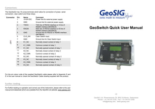
- 1. Connections The GeoSwitch has 16 screw terminals which allow for connection of power, serial connection, clear switch and three relays. Connector Pin Name Comment J201 1 +9-28 VDC Power line for external power supply 2 GND Ground line for external power supply 3 TXD/A TXD line of RS232 interface or A line of RS485 interface (MODBUS) 4 RXD/B RXD line of RS232 interface or B line of RS485 interface (MODBUS) 5 GND Ground line for RS232 or RS485 interface (MODBUS) 6 CLR_SW Clear Switch input 7 GND Ground line for Clear Switch input 8 K1_NC Normally closed contact of relay 1 9 K1_CMN Common contact of relay 1 10 K1_NO Normally opened contact of relay 1 11 K2_NC Normally closed contact of relay 2 12 K2_CMN Common contact of relay 2 13 K2_NO Normally opened contact of relay 2 14 K3_NC Normally closed contact of relay 3 15 K3_CMN Common contact of relay 3 16 K3_NO Normally opened contact of relay 3 For the pin colour code of the supplied GeoSwitch cable please refer to Appendix D and E in the user manual or check the GeoSwitch Cable drawing supplied with the product. Further reading For further reading on operation and correct use of the instrument, please refer to the user manual and datasheet which are available from the GeoSIG Ltd website: www.geosig.com GeoSwitch Quick User Manual V3 GeoSIG Ltd, Wiesenstrasse 39, 8952 Schlieren, Switzerland Phone: + 41 44 810 2150, Fax: + 41 44 810 2350 info@geosig.com, www.geosig.com
- 2. Foreword Thank you for buying this GeoSIG Ltd GeoSwitch. This manual is provided as a brief guideline to give an overview of the first steps and it is not intended to cover all the different circumstances. Please check the GeoSwitch User Manual for details. Unpacking The GeoSwitch is shipped in a standard packing box containing GeoSwitch and Quick User Manual. Specially ordered accessories may be included in the box or shipped in a separate box. The packing box must be inspected for any external damage and any damage should be immediately reported to the forwarder. The contents of the packing box can be checked according to the order and the packing list. Verify that none of the items have physical damage. Keep the packing box for transportation to the final location of the instrument. Indicators The LED’s on the front panel signal the following conditions: POWER Flashes when GeoSwitch is running. ERROR Illuminates to indicate an error condition. WARNING Illuminates to indicate a warning condition. ALARM Illuminates to indicate an active alarm Installation The unit must be fixed rigidly on the foundation. For that purpose, the housing has mounting flanges for fixation, where two or four M4 screws with washers should be used. The GeoSwitch contains an internal offset correction. Therefore the instrument can be installed on the floor, wall or any other oriented surface without any limitations. Configuration The GeoSwitch can be configured in several ways: § Using the free GeoSwitch ConfiguratorTM tool (Windows and OS X) § Via the console, using a USB cable and serial terminal program § Via display and push buttons Connect To connect to the GeoSwitch using GeoSwitch ConfiguratorTM : § Power the GeoSwitch and connect a USB cable between the GeoSwitch and a computer running GeoSwitch ConfiguratorTM . § Open the GeoSwitch ConfiguratorTM and click on the “disconnected” button to open the connection dialog. § Select the correct COM port and choose a baud rate of 115200 and click OK. § The GeoSwitch is now connected, and parameters can be changed from GeoSwitch ConfiguratorTM . To connect to the GeoSwitch using a serial terminal program: § Power the GeoSwitch and connect a USB cable between the GeoSwitch and a computer. § Start your serial terminal program and connect to the correct COM port using baud rate 115200 with 8N1. § Press “return” an you should see ch> printed on the terminal. § Type help or refer to user manual for full overview of commands. To configure the GeoSwitch using the LCD and push buttons: § Press the “enter” push button to bring up the main menu on the LCD. § Navigate the menus using the “up” and “down” push buttons. § Use the “enter” push button to enter sub menus, select parameters and confirm settings. Figure 1. Connection dialog. Figure 2. Navigation push buttons. Inches [mm]