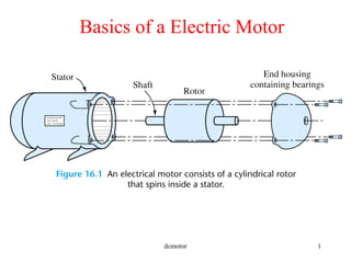
5. dcmotor 5
FORE FINGER = MAGNETIC FIELD
900
900
900
MIDDLE FINGER= CURRENT
THUM
B
=
M
OTION
FORCE = B IAl
Fleming’s Left Hand Rule Or
Motor Rule
6. dcmotor 6
FORE FINGER = MAGNETIC FIELD
900
900
900
MIDDLE FINGER = INDUCED
VOLTAGE
TH
U
M
B
=
M
O
TIO
N
VOLTAGE = B l u
Fleming’s Right Hand Rule Or
Generator Rule
15. dcmotor 15
Summary of a DC Machine
• Basically consists of
1. An electromagnetic or permanent magnetic structure called
field which is static
2. An Armature which rotates
• The Field produces a magnetic medium
• The Armature produces voltage and torque under the action
of the magnetic field
18. dcmotor 18
Voltage and Torque developed in a
DC Machine
•Induced EMF, Ea = KaΦωm (volts)
•Developed Torque, Tdev = KaΦIa (Newton-meter
or Nm)
where ωm is the speed of the armature in rad/sec.,
Φ is the flux per pole in weber (Wb)
Ia is theArmature current
Ka is the machine constant
19. dcmotor 19
Interaction of Prime-mover DC Generator
and Load
Prime-mover
(Turbine)
DC Generator
Load
Ia
Tdev
ωm Ea
+
-
VL
+
-Tpm
Ea is Generated voltage
VL is Load voltage
Tpm is the Torque generated by Prime Mover
Tdev is the opposing generator torque
20. dcmotor 20
Interaction of the DC Motor
and Mechanical Load
DC Motor
Mechanical
Load
(Pump,
Compressor)
Tload
ωmEa
+
- Tdev
Ea is Back EMF
VT is Applied voltage
Tdev is the Torque developed by DC Motor
Tload is the opposing load torque
Ia
VT
+
--
21. dcmotor 21
Power Developed in a DC Machine
•Input mechanical power to dc generator
= Tdev ωm= KaΦIaωm =Ea Ia
= Output electric power to load
•Input electrical power to dc motor
= Ea Ia=KaΦ ωm Ia = Tdev ωm
= Output mechanical power to load
Neglecting Losses,
22. dcmotor 22
Equivalence of motor and generator
•In every generator there is a motor (Tdev opposes Tpm)
•In every motor there is a generator (Ea opposes VT)
24. dcmotor 24
Magnetization Curve
maa KE ωΦ=
•Flux is a non-linear
function of field current and
hence Ea is a non-linear
function of field current
•For a given value of flux Ea
is directly proportional to
ωm
28. dcmotor 28
Shunt Field Coil Armature
RA
Compound Excited DC Machine
Series Field Coil
•If the shunt and series field aid each other it is called a cumulatively
excited machine
•If the shunt and series field oppose each other it is called a differentially
excited machine
29. dcmotor 29
Armature Reaction(AR)
• AR is the magnetic field produced by the
armature current
•AR aids the main flux in one half of the
pole and opposes the main flux in the
other half of the pole
•However due to saturation of the pole
faces the net effect of AR is demagnetizing
30. dcmotor 30
Effects of Armature Reaction
• The magnetic axis of the AR
is 900
electrical (cross) out-of-
phase with the main flux. This
causes commutation
problems as zero of the flux
axis is changed from the
interpolar position.
31. dcmotor 31
Minimizing Armature Reaction
•Since AR reduces main flux, voltage in
generators and torque in motors reduces
with it. This is particularly objectionable
in steel rolling mills that require sudden
torque increase.
•Compensating windings put on pole
faces can effectively negate the effect
of AR. These windings are connected
in series with armature winding.
32. dcmotor 32
Minimizing commutation problems
•Smooth transfer of current during
commutation is hampered by
a) coil inductance and
b) voltage due to AR flux in the
interpolar axis. This voltage is called
reactance voltage.
•Can be minimized using interpoles.
They
produce an opposing field that cancels
out the AR in the interpolar region. Thus
this winding is also connected in series
with the armature winding.
Note: The UVic lab motors have
interpoles in them. This should be
connected in series with the armature
winding for experiments.
35. dcmotor 35
Shunt Generators
Field equation: Vt=Rf If
Rf=Rfw+Rfc
Armature equation: Vt=Ea-Ia Ra
Vt=(Ia – If) RL, Ea=KaΦωm
Shunt Field Coil Armature
Ra
RL
If Ia
Ia – If
Vt
+
-
Rfc
Ea
+
-
Field coil has Rfw :
Implicit field resistance
37. dcmotor 37
Example on shunt generators’ buildup
For proper voltage build-up the
following are required:
• Residual magnetism
• Field MMF should aid residual
magnetism
•Field circuit resistance should be less
than critical
field circuit resistance
40. dcmotor 40
Separately excited DC Motor-Example I
A dc motor has Ra =2 Ω, Ia=5 A, Ea = 220V, Nm = 1200 rpm.
Determine i) voltage applied to the armature, developed torque,
developed power . ii) Repeat with Nm = 1500 rpm. Assume same
Ia.
Solution on Greenboard
41. dcmotor 41
Speed Control of Separately Excited
DC Motor(2)
•By Controlling Terminal Voltage Vt and keeping If or Φ
constant at rated value .This method of speed control is applicable
for speeds below rated or base speed.
ωm
VT
T1 T2 T3
T1<T2< T3
T
K
R
K
V
a
a
a
t
m 2
)( ΦΦ
ω −=
V1<V2<V3
V1
V2 V3
42. dcmotor 42
Speed Control of Separately Excited
DC Motor
•By Controlling(reducing) Field Current If or Φ and keeping
Vt at rated value. This method of speed control is applicable
for speeds above rated speed.
ωm
T1
T2
T3
T1<T2< T3
Φ
T
K
R
K
V
a
a
a
t
m 2
)( ΦΦ
ω −=
ω1
ω1> ω 2> ω 3
ω2
ω3
44. dcmotor 44
A separately excited dc motor with negligible armature resistance
operates at 1800 rpm under no-load with Vt =240V(rated voltage).
The rated speed of the motor is 1750 rpm.
i) Determine Vt if the motor has to operate at 1200 rpm under no-load.
ii) Determine Φ(flux/pole) if the motor has to operate at 2400 rpm
under no-load; given that K = 400/π.
iii) Determine the rated flux per pole of the machine.
Separately excited dc motor –Example 2
Solution on Greenboard
45. dcmotor 45
Series Field Coil
Armature
Ra
Series Excited DC Motor
Torque-Speed Characteristics
ωm
T
sr
aesra
sr
t
m
K
RRR
TK
V ++
−=ω
Rsr Rae
-
+
47. dcmotor 47
Losses in dc machines-shunt motor
example
Field equation: Vt=Rf If
Rf=Rfw+Rfc
Armature equation: Vt=Ea+Ia Ra
Ea=KaΦωm
Shunt Field Coil
Armature
Ra
If Ia
Ia – If
Vt
+
-
Rfc
Ea
+
-
Field coil has Rfw :
Implicit field resistance
Mechanical Load