
Recommended
Recommended
More Related Content
What's hot
What's hot (20)
Similar to How to make periodic boundary condition
Similar to How to make periodic boundary condition (20)
Recently uploaded
Recently uploaded (20)
How to make periodic boundary condition
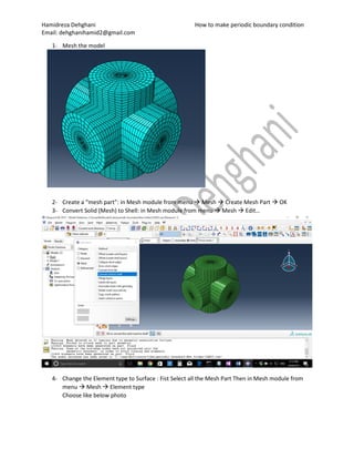
- 1. Hamidreza Dehghani How to make periodic boundary condition Email: dehghanihamid2@gmail.com 1- Mesh the model 2- Create a “mesh part”: in Mesh module from menu Mesh Create Mesh Part OK 3- Convert Solid (Mesh) to Shell: in Mesh module from menu Mesh Edit… 4- Change the Element type to Surface : Fist Select all the Mesh Part Then in Mesh module from menu Mesh Element type Choose like below photo
- 2. Hamidreza Dehghani How to make periodic boundary condition Email: dehghanihamid2@gmail.com 5- Delete all the elements and nodes except one surface that you want to make periodic boundary condition: in Mesh module from menu Mesh Edit… Then choose all the elements that you want to delete Take into account that still there are nodes that you should delete
- 3. Hamidreza Dehghani How to make periodic boundary condition Email: dehghanihamid2@gmail.com Then delete nodes You can select all and deselect the nodes that you need by holding Ctrl
- 4. Hamidreza Dehghani How to make periodic boundary condition Email: dehghanihamid2@gmail.com 6- Copy the surface that you have in other sides that you want to create boundary condition: in Assembly module Create instance choose Fluid-Mesh-1 (the surface that you made) In model tree in assembly hide the other model to see just the surface
- 5. Hamidreza Dehghani How to make periodic boundary condition Email: dehghanihamid2@gmail.com Then, Instance Radial pattern select the surface done select axis: choose Z-axis Then you can have them in X-Y plane by radial patter of the two surfaces in X-Z plane around X-axis
- 6. Hamidreza Dehghani How to make periodic boundary condition Email: dehghanihamid2@gmail.com 7- Put all the surfaces in one instance: Instance Merge/Cut
- 7. Hamidreza Dehghani How to make periodic boundary condition Email: dehghanihamid2@gmail.com 8- Create section and assign it to our Meshpart surfaces. In property module Material Manager Create…
- 8. Hamidreza Dehghani How to make periodic boundary condition Email: dehghanihamid2@gmail.com Then, Section Manager Create… Then, OK.
- 9. Hamidreza Dehghani How to make periodic boundary condition Email: dehghanihamid2@gmail.com Note that it should be really weak compared to our original model because we do not want it to affect our results. Section assignment manager Create… Ok.
- 10. Hamidreza Dehghani How to make periodic boundary condition Email: dehghanihamid2@gmail.com 9- Delete unnecessary sets: until now as you can see in the above photo we have 49 sets that just 7 of them are valid. The reason is that using several times of copy. So first it is better to delete invalid sets: In part module you can delete them like in the following photo 10- Create necessary sets for Tie and Equation: we need to put each surface that we are made in one Node set and also we need to create some Geometry sets from each surface in original geometry corresponded with its mesh surface… In assembly module Tools Set Manager
- 11. Hamidreza Dehghani How to make periodic boundary condition Email: dehghanihamid2@gmail.com You can choose any name that you want but in this file this name refers to a node set from our Meshpart in the surface normal to X-axis and in positive part of X-axis Continue this step and make one set for each surface of our meshpart. Then we should make Geometry Sets from each surface of our original geometry corresponded to our Meshpart surfaces to make Tie between them. To select surfaces in our original assembly we can hide the Mesh-Part-1 and show the Fluid-1
- 12. Hamidreza Dehghani How to make periodic boundary condition Email: dehghanihamid2@gmail.com Then again in assembly module Tools Set Manager
- 13. Hamidreza Dehghani How to make periodic boundary condition Email: dehghanihamid2@gmail.com Hold Ctrl key and deselect all the outer borders of the selected geometry to become like this: Then make a Geometry set of one node (it is not important which one) and name it as “Node”. We will use this set in future for a trick In the end, we should have the sets like the highlighted ones in the following photo.
- 14. Hamidreza Dehghani How to make periodic boundary condition Email: dehghanihamid2@gmail.com 11- Tie the Meshpart surfaces to their corresponding surfaces in the original geometry: Interaction module constraint manager create.. Choose the Node Region:
- 15. Hamidreza Dehghani How to make periodic boundary condition Email: dehghanihamid2@gmail.com In right hand side click on “sets…” By checking the box of “Highlight selection in the viewport”, you will see the Set in the viewport like the above photo. Click on Continue.
- 16. Hamidreza Dehghani How to make periodic boundary condition Email: dehghanihamid2@gmail.com Choose Node Region Continue… Normally, the stronger region should be the Master surface (like what we have done until here) but the point is that as then in the Equation part the Meshpart surface will be the master surface we should put it here as the Master as well because one region cannot be Master and Slave in the same file… By clicking on continue you will see the below window.
- 17. Hamidreza Dehghani How to make periodic boundary condition Email: dehghanihamid2@gmail.com Click on Switch surfaces and then OK… Do this for all sides and make all Ties like the ones that are highlighted in the following photo. 12- Create Equation constraints: Here we will make periodic boundary condition Interaction module constraint manager create…
- 18. Hamidreza Dehghani How to make periodic boundary condition Email: dehghanihamid2@gmail.com This is what we want to create: However, by clicking OK we will have and error:
- 19. Hamidreza Dehghani How to make periodic boundary condition Email: dehghanihamid2@gmail.com Nevertheless, we know that it is possible to make Equation Constraints between two surfaces that are equal (Equality here is the reason of making new meshpart surfaces). Therefore, we should use a trick to do that… In the second line, we choose a Set that we have made from a single Node. And make Equation Constraints for all sides.
- 20. Hamidreza Dehghani How to make periodic boundary condition Email: dehghanihamid2@gmail.com Do the same for other sides to have the following highlighted constraints:
- 21. Hamidreza Dehghani How to make periodic boundary condition Email: dehghanihamid2@gmail.com 13- Replace the Set “Node” in the second line with sets “meshpart-node-X- (or Y- or Z- in their cases)” To do that we need to make an input file (.INP) from this model and change it from there. In Job module Job Manger Create Create one job with all the default setting: Click on Write input Go to the direction of work directory in windows and open the file ‘your job name’.inp (here it is Fluidpart-periodicZ). In that file find *Equation
- 22. Hamidreza Dehghani How to make periodic boundary condition Email: dehghanihamid2@gmail.com Change the word “Node” with the couple of the first set in each one.
- 23. Hamidreza Dehghani How to make periodic boundary condition Email: dehghanihamid2@gmail.com 14- Run it: Open “Abaqus Commands” write CD “the direction of edited input file” and click Enter Then write: abaqus job=”the input file name”.inp inte and click Enter