SlideShare a Scribd company logo
1 of 104
Download to read offline
SPECTRUM 3 SINGLE-RANGE IR
SYSTEMS
User’s Guide
MOLECULAR SPECTROSCOPY
Release History
Part Number Release Publication Date
L1050110 B June 2020
Any comments about the documentation for this product should be addressed to:
User Assistance
PerkinElmer Ltd
Chalfont Road
Seer Green
Beaconsfield
Bucks HP9 2FX
United Kingdom
Or emailed to: IRTechSupport@perkinelmer.com
Notices
The information contained in this document is subject to change without notice.
Except as specifically set forth in its terms and conditions of sale, PerkinElmer makes no
warranty of any kind with regard to this document, including, but not limited to, the
implied warranties of merchantability and fitness for a particular purpose.
PerkinElmer shall not be liable for errors contained herein for incidental consequential damages in
connection with furnishing, performance or use of this material.
Copyright Information
This document contains proprietary information that is protected by copyright.
All rights are reserved. No part of this publication may be reproduced in any form whatsoever or
translated into any language without the prior, written permission of PerkinElmer, Inc.
Copyright © 2020 PerkinElmer, Inc.
Produced in the United Kingdom.
Trademarks
Registered names, trademarks, etc. used in this document, even when not specifically marked as such,
are protected by law.
PerkinElmer is a registered trademark of PerkinElmer, Inc.
Spectrum IR, Spotlight, AssureID and Spectrum 3 are trademarks of PerkinElmer, Inc.
Contents
Introduction...............................................................................................5
About This Manual ............................................................................................ 6
Conventions Used in this Manual........................................................................ 7
Notes, Cautions and Warnings..................................................................... 7
Warnings and Safety Information ...........................................................11
Safety Summary...............................................................................................12
General Safety .................................................................................................13
Location and Ventilation ...................................................................................14
To allow for adequate cooling ....................................................................14
To allow any nitrogen used to disperse .......................................................14
Use of flammable solvents and samples ......................................................15
Electrical Safety ...............................................................................................17
Laser Safety Regulations...................................................................................18
Radiation Hazards and their Classification ..........................................................19
Laser radiation ..........................................................................................19
Radiation emitted by an NIR source............................................................19
Labels .............................................................................................................20
Warning Signs on the Instrument......................................................................21
EMC Compliance ..............................................................................................22
European EMC Directive.............................................................................22
FCC rules and regulations...........................................................................22
Precautions when operating .......................................................................22
An Overview of the Spectrum 3 Single-Range Spectrometers ................23
A Guided Tour of the Spectrum 3 Single-Range Spectrometers ...........................24
Optical system...........................................................................................25
Top panel controls.....................................................................................26
The sample compartment ..........................................................................26
Internal accessories...................................................................................28
External accessories...................................................................................29
The Spotlight 400 Series Imaging System ...................................................30
Power switch and communications ports .....................................................30
Accessories for the Spectrum 3 Spectrometer ....................................................31
Spectrum 3 Systems Upgrades..........................................................................33
Unpacking and Installation......................................................................35
Requirements ..................................................................................................36
Electrical requirements...............................................................................36
Environment..............................................................................................36
Unpacking the spectrometer .............................................................................37
Opening the shipping container ..................................................................37
The Desiccant Indicator....................................................................................39
Connecting up the Spectrometer.......................................................................40
Connecting to the PC .................................................................................40
Other connectors.......................................................................................41
Connecting the spectrometer to the electrical supply ...................................42
Installing the Instrument in the Software...........................................................44
Installing the software ...............................................................................44
The Instrument Install Wizard ....................................................................44
Using the Spectrometer with Spectrum IR..............................................45
Basics of Software Control ................................................................................46
Starting Spectrum IR software....................................................................46
Scanning samples......................................................................................47
Working with the instrument display and buttons ........................................48
Changing the beampath.............................................................................49
Using the Spectrum IR on-screen Help system ............................................50
Atmospheric (CO2/H2O) Suppression..................................................................51
What is atmospheric suppression? ..............................................................51
What does atmospheric suppression do? .................................................... 51
AVI Correction................................................................................................. 53
What is AVI correction? ............................................................................. 53
What does AVI correction do?.................................................................... 54
Quality Checks................................................................................................. 55
What are Quality Checks?.......................................................................... 55
What do Quality Checks do? ...................................................................... 55
Routine Maintenance ...............................................................................57
Cleaning the Spectrometer ............................................................................... 58
Cleaning the display .................................................................................. 58
Moving the Spectrometer ................................................................................. 59
Condensation............................................................................................ 60
The Desiccant Indicator in Detail ...................................................................... 61
Changing the Desiccant.................................................................................... 62
Renewing the instrument desiccant............................................................ 63
Installing rechargeable desiccant in the instrument ..................................... 64
Purging the Spectrometer ................................................................................ 65
Changing the External Fuse.............................................................................. 68
Cooling the MCT Detector (If Fitted) ................................................................. 70
Advanced Maintenance ............................................................................73
Opening the Main Cover................................................................................... 74
Replacing a Source .......................................................................................... 78
Replacing the Beamsplitter............................................................................... 81
Installing/Replacing Beam Port and Sample Compartment Windows ................... 83
Installing Filters in the Filter Wheel................................................................... 85
Replacing the Laser and Power Supply.............................................................. 89
Replacing the HeNe laser........................................................................... 89
Appendices...............................................................................................95
Appendix 1: Changing the Sample Area Accessory............................................. 96
Appendix 2: Instrument Self-Checks ................................................................. 98
Appendix 3: Instrument Performance Validation .............................................. 100
Appendix 4: Decontamination and Cleaning..................................................... 101
Appendix 5: WEEE Instructions for PerkinElmer Products ................................. 102
Index............................................................................................................ 103
Introduction
6 . Spectrum 3 Single-Range IR Systems User's Guide
About This Manual
This manual contains the following sections:
• Introduction
• Warnings and Safety Information
• An Overview of the Spectrum 3 Single-Range IR Spectrometers
• Unpacking and Installation
• Using the Spectrometer with Spectrum
• Routine Maintenance
• Advanced Maintenance
• Appendices
For further information on collecting, viewing and processing spectra using Spectrum
software, refer to the help file that you can access from the Help menu, or by clicking Help
on a dialog. The Help menu also includes links to on-screen tutorials.
NOTE: This manual shows details for using your instrument with the Spectrum software
package (version 10.7 or later). If you have Spectrum ES or AssureID software,
please refer to the Administrator’s Guide for your software which can be found on the
Software USB, or refer to the on-screen Help.
Introduction . 7
Conventions Used in this Manual
Normal text is used to provide information and instructions.
Bold text refers to text that is displayed on the screen.
UPPERCASE text, for example ENTER or ALT, refers to keys on the PC keyboard. '+' is
used to show that you have to press two keys at the same time, for example, ALT+F.
All eight-digit numbers are PerkinElmer part numbers unless stated otherwise.
The term “instrument” refers to a Spectrum 3 infrared spectrometer, and any sampling
accessory fitted. Spectrum 3 Single-Range spectrometer refers to the Spectrum 3 FT-MIR
and FT-NIR spectrometers.
Notes, Cautions and Warnings
Three terms, in the following standard formats, are also used to highlight special
circumstances and warnings.
NOTE: A note indicates additional, significant information that is provided with some
procedures.
8 . Spectrum 3 Single-Range IR Systems User's Guide
CAUTION
We use the term CAUTION to inform you about situations that could
result in serious damage to the instrument or other equipment. Details
about these circumstances are in a box like this one.
Caution (Achtung)
Bedeutet, daß die genannte Anleitung genau befolgt werden muß, um
einen Geräteschaden zu vermeiden.
Caution (Bemærk)
Dette betyder, at den nævnte vejledning skal overholdes nøje for at undgå
en beskadigelse af apparatet.
Caution (Advertencia)
Utilizamos el término CAUTION (ADVERTENCIA) para advertir sobre
situaciones que pueden provocar averías graves en este equipo o en otros.
En recuadros éste se proporciona información sobre este tipo de
circunstancias.
Caution (Attention)
Nous utilisons le terme CAUTION (ATTENTION) pour signaler les
situations susceptibles de provoquer de graves détériorations de
l'instrument ou d'autre matériel. Les détails sur ces circonstances figurent
dans un encadré semblable à celui-ci.
Caution (Attenzione)
Con il termine CAUTION (ATTENZIONE) vengono segnalate situazioni
che potrebbero arrecare gravi danni allo strumento o ad altra
apparecchiatura. Troverete informazioni su tali circostanze in un
riquadro come questo.
Caution (Opgelet)
Betekent dat de genoemde handleiding nauwkeurig moet worden
opgevolgd, om beschadiging van het instrument te voorkomen.
Caution (Atenção)
Significa que a instrução referida tem de ser respeitada para evitar a
danificação do aparelho.
Caution (小心)
我们使用“小心”这一术语来通知您有关可能会对
本仪器或其它设备造成严重损害的情况。
有关这些情况的详细信息可在此类方框中找到。
Caution (注意)
分光器や他の機材等に深刻なダメージを与える恐れがある場合は、
この様なボックスの中に表示しています。
Introduction . 9
WARNING
We use the term WARNING to inform you about situations that could result in
personal injury to yourself or other persons. Details about these
circumstances are in a box like this one.
Warning (Warnung)
Bedeutet, daß es bei Nichtbeachten der genannten Anweisung zu einer
Verletzung des Benutzers kommen kann.
Warning (Advarsel)
Betyder, at brugeren kan blive kvæstet, hvis anvisningen ikke overholdes.
Warning (Peligro)
Utilizamos el término WARNING (PELIGRO) para informarle sobre
situaciones que pueden provocar daños personales a usted o a otras
personas. En los recuadros como éste se proporciona información sobre este
tipo de circunstancias.
Warning (Danger)
Nous utilisons la formule WARNING (DANGER) pour avertir des situations
pouvant occasionner des dommages corporels à l'utilisateur ou à d'autres
personnes. Les détails sur ces circonstances sont données dans un encadré
semblable à celui-ci.
Warning (Pericolo)
Con il termine WARNING (PERICOLO) vengono segnalate situazioni che
potrebbero provocare incidenti alle persone. Troverete informazioni su tali
circostanze in un riquadro come questo.
Warning (Waarschuwing)
Betekent dat, wanneer de genoemde aanwijzing niet in acht wordt genomen,
dit kan leiden tot verwondingen van de gebruiker.
Warning (Aviso)
Significa que a não observância da instrução referida poderá causar um
ferimento ao usuário.
Warning (警告)
我们使用“警告”这一术语来通知您有关可能会对您自己或他人造成人
身伤害的情况。
有关这些情况的详细信息可在此类方框中找到。
Warning (警告)
使用者及びその他周辺に危害が及ぶ恐れがある場合は、
この様なボックスの中に注意事項が表示されています。
10 . Spectrum 3 Single-Range IR Systems User's Guide
Warnings and Safety
Information
12 . Spectrum 3 Single-Range IR Systems User's Guide
Safety Summary
The Spectrum 3 spectrometers have been designed to comply with a wide variety of
international standards governing the safety of laboratory equipment. In routine use, the
instruments pose virtually no risk to you. If you take some simple, common-sense
precautions, you can make sure that you maintain the continued safe operation of your
instrument:
DO make sure that the instrument is properly connected to the electrical supply; in particular
make sure that the ground (earth) is securely connected.
DO disconnect the electrical power cable before opening the main cover of the instrument.
DO keep the instrument dry. Avoid spilling liquid into the instrument. Clean all external spills
immediately. If anything that is spilled enters the main body of the instrument, switch off the
power and contact a PerkinElmer Service Engineer.
DO NOT stare into the internal laser beam under the instrument cover. The instrument
contains a low power laser which may be visible (red) or invisible depending on the type of
laser installed; momentary exposure to the beam is not dangerous, but deliberate, direct
viewing of the beam along its axis could damage your eye.
DO NOT use a flammable gas to purge the instrument. The instrument contains a hot source,
and a fire or explosion will result. Only use clean, dry, oil-free nitrogen or air to purge the
instrument.
DO read the more detailed information on warnings and safety in the following pages to
ensure the safe operation of the instrument.
Warnings and Safety Information . 13
General Safety
The Spectrum 3 spectrometers have been designed and tested in accordance with
PerkinElmer specifications and in accordance with the safety requirements of the
International Electrotechnical Commission (IEC). The instruments conform to IEC publication
61010-1 (“Safety requirements for electrical equipment for measurement, control, and
laboratory use”) as it applies to IEC Class 1 (earthed) appliances and therefore meets the
requirements of EU Low Voltage Directive 2014/35/EU.
If the instrument is used in a manner not specified by the manufacturer, the protection
provided by the instrument may be impaired. Only use the instrument indoors and under the
following conditions:
Temperature 15 °C to 35 °C
Relative Humidity 80% maximum (non-condensing)
If possible, avoid any adjustment, maintenance and repair of the opened, operating
instrument. If any adjustment, maintenance and repair of the opened, operating instrument
is necessary, this must only be done by a skilled person who is aware of the hazard involved.
Whenever it is likely that the instrument is unsafe, make it inoperative. The instrument may
be unsafe if it:
• Shows visible damage
• Fails to perform the intended measurement
• Has been subjected to prolonged storage in unfavorable conditions
• Has been subjected to severe transport stresses.
WARNING
AVERTISSEMENT
The protection provided by this equipment may be impaired if the
equipment is used in a manner not specified by PerkinElmer.
La protection fournie par cet équipement risque d'être moins efficace si
l'équipement fait l'objet d'une utilisation différente de celle mentionnée
par PerkinElmer.
The instrument has been designed to be safe under the following environmental conditions:
• Indoor use
• Altitude up to 2000 m (above mean sea level)
• Ambient temperatures of 5 °C to 40 °C
• A maximum ambient relative humidity of 80% for temperatures up to 31 °C, decreasing
linearly to 50% relative humidity at 40 °C
• Mains supply fluctuations not exceeding ±10% of the nominal voltage.
14 . Spectrum 3 Single-Range IR Systems User's Guide
Location and Ventilation
WARNING
AVERTISSEMENT
Make sure that the switch at the electrical supply inlet on the rear of
the instrument is not obstructed.
Assurez-vous que l’interrupteur de l’alimentation électrique situé à
l’arrière de l’instrument n’est pas obstrué.
To allow for adequate cooling
Do not locate the instrument near to room heating equipment, for example, central heating
radiators.
During operation, there should be a minimum gap of:
• 15 cm (6 inches) between any surface and the cooling louvers at the rear of the
instrument.
• 7 cm (3 inches) between the instrument and adjacent equipment.
• 45 cm (18 inches) between any surface and the top surface of the closed sample area
lid (to allow for the lid to be opened fully).
To allow any nitrogen used to disperse
WARNING
AVERTISSEMENT
Do not site the instrument in a poorly ventilated area if nitrogen will be
used as a purge gas, or if liquid nitrogen will be used to cool a
detector.
Oxygen depletion in an enclosed space does not trigger a gasping
reflex, and errors of judgment, confusion, or unconsciousness can
occur in seconds and without warning.
Ne placez pas l’instrument dans un endroit mal ventilé si de l’azote doit
être utilisé comme gaz de purge, ou si de l’azote liquide doit être utilisé
pour refroidir un détecteur.
L’appauvrissement en oxygène d’un espace clos ne déclenche pas de
réflexe de halètement, et des erreurs de jugement, de la confusion ou
une perte de conscience peuvent survenir en quelques secondes sans
prévenir.
The spectrometer includes a coupling that enables the instrument body, and another
coupling that enables the sample compartment, to be purged using clean, dry, oil-free air or
nitrogen. The recommended flow rate to each connector is 10 l/min, and both the instrument
and the sample compartment vent to their surroundings.
If the instrument is fitted with an MCT detector, this is cooled using liquid nitrogen. A risk
assessment should include personal protection protocols, and proper actions in the event of
accidental spillage. 1 l (2 US pints) of liquid nitrogen evolves to 700 l (approximately
25 cubic feet) of nitrogen gas, and the cold vapor can pool at floor level.
Warnings and Safety Information . 15
Use of flammable solvents and samples
WARNING
AVERTISSEMENT
The instrument contains a hot source and contact with flammable
vapors may cause an explosion. When working with flammable
solvents or samples, particularly during unattended operation with
flow-cells, it is recommended that the instrument optics area should be
continuously purged with dry air or nitrogen to maintain a positive
pressure and prevent flammable vapor from entering the instrument.
L’instrument contient une source chaude. Le contact avec des vapeurs
inflammables peut provoquer une explosion. Lorsque vous travaillez
avec des solvants ou des échantillons inflammables, en particulier lors
d’opérations sans surveillance avec des cuves à circulation, il est
recommandé de purger en continu la zone des optiques de l’instrument
avec de l’air sec ou de l’azote afin de maintenir une pression positive et
d’éviter aux vapeurs inflammables de pénétrer dans l’instrument.
WARNING
AVERTISSEMENT
If flammable solvents or samples are spilled on the instrument and
there is any possibility that they have entered the interior (by coming
into contact with cover gaskets, for example) then the instrument must
be switched off immediately and disconnected from the power supply.
The optics area should then be thoroughly purged with dry air or
nitrogen, or the main cover should be opened to thoroughly ventilate
the optics area before proceeding.
Si des solvants ou échantillons inflammables sont renversés sur
l’instrument et s’il existe une possibilité qu’ils aient pénétré à l’intérieur
de l’instrument (en entrant en contact avec les joints du couvercle par
exemple), l’instrument doit être éteint immédiatement et débranché de
l’alimentation électrique. La zone contenant les optiques doit ensuite
être purgée à fond avec de l’air sec ou de l’azote, ou le couvercle
principal doit être ouvert pour bien ventiler la zone des optiques avant
de continuer.
WARNING
AVERTISSEMENT
Flammable solvents or samples should not be stored on or near the
instrument. Handling of such materials during preparation should be
performed in a safe area away from the instrument such as a fume
cabinet.
Des solvants ou des échantillons inflammables ne doivent pas être
stockés sur ou à proximité de l’instrument. La manipulation de ces
matières pendant une préparation doit être effectuée dans un endroit
sûr, loin de l’instrument, tel qu’une hotte.
16 . Spectrum 3 Single-Range IR Systems User's Guide
WARNING
AVERTISSEMENT
Do not use a flammable gas to purge the Spectrum 3 instruments. Use
only clean, dry, oil-free nitrogen or air.
N’utilisez pas de gaz inflammables pour purger les spectromètres
Spectrum 3. Utilisez uniquement de l’azote ou de l’air propre, sec et
exempt d’huile pour purger l’instrument.
Warnings and Safety Information . 17
Electrical Safety
• Connect the instrument to a power supply line that includes a switch or other means of
disconnection from the electricity supply.
• Only plug the instrument into an electricity-supply socket that is provided with a
protective earth connection.
• When fuses need replacing, use only those with the required current rating and of the
specified type. Do not use makeshift fuses and do not short-circuit fuse holders.
• When the instrument is connected to its electricity supply, terminals may be live and the
removal of covers other than those which can be removed by hand is likely to expose
live parts.
• Capacitors inside the instrument may still be charged even if the instrument has been
disconnected from all voltage sources.
• The instrument must be disconnected from all voltage sources before it is opened for
any adjustment, replacement, maintenance or repair.
WARNING
AVERTISSEMENT
Any interruption of the protective conductor (earth ground) inside or
outside the instrument or disconnection of the protective conductor
terminal is likely to make the instrument dangerous.
Toute interruption du conducteur de protection (mise à la terre) à
l'intérieur ou à l'extérieur de l'instrument ou toute déconnexion de la
borne du conducteur de protection risque de rendre l'instrument
dangereux.
The instrument has an IEC Insulation Class I rating for external circuits – only connect other
equipment that meets the requirements of IEC 61010-1, IEC 60950 or equivalent standards.
18 . Spectrum 3 Single-Range IR Systems User's Guide
Laser Safety Regulations
The Spectrum 3 spectrometers are Class 1 laser products as defined by IEC 60825-1. The
optical module contains:
a Class 2 Helium Neon (HeNe) laser, which emits visible, continuous wave radiation at a
wavelength of 633 nm and has a maximum output power of 1 mW
OR
a Class 1 diode laser, which emits invisible, continuous wave radiation at a wavelength of
850 nm and has a maximum output power of 0.6 mW.
Some diffuse laser radiation, within Class 1 limits, emerges from:
• The window in the left side of the sample compartment when an internal beam path is
selected.
• An external beam port when the port cover is removed, no accessory is fitted at the
port, and the beam path to the port is selected.
The laser is automatically shut down when the main cover of the instrument is raised.
The instrument complies with the following laser safety regulations:
1. 21 CFR Part 1040.10 and 1040.11 except for deviations pursuant to Laser Notice No. 50
dated 24 June 2007. Administered by the Center for Devices and Radiological Health,
U.S. Department of Health and Human Services.
2. European Standard EN 60825-1:2014 – “Safety of laser products – Part 1: Equipment
classification and requirements”.
WARNING
AVERTISSEMENT
Do not stare into any laser beam. Staring into a laser beam (intrabeam
viewing) can cause permanent damage to your eyes.
Ne fixez pas le faisceau laser. Regarder fixement un faisceau laser
(visualisation intrafaisceaux) peut causer des dommages permanents à
vos yeux.
WARNING
AVERTISSEMENT
Do not attempt to override or modify the interlock system.
Use of controls or adjustments or performance of procedures other
than those specified herein may result in hazardous radiation exposure.
N’essayez pas de remplacer ou de modifier le système de verrouillage.
L’utilisation de commandes ou de réglages ou l’exécution de
procédures autres que celles spécifiées dans le présent document peut
entraîner une exposition dangereuse à des rayonnements.
Warnings and Safety Information . 19
Radiation Hazards and their Classification
Laser radiation
Indirect observation of the laser beam radiation in the optical path is not hazardous. Directly
viewing the laser beam along its axis (allowing the laser beam radiation to pass into the eye)
can be hazardous, depending upon the power of the beam, the length of time that the eye is
exposed to the beam and the optical efficiency of the exposed eye. Direct viewing of a laser
beam along its axis is termed intrabeam viewing.
Protection of the eye during accidental, momentary intrabeam viewing of a Class 2 HeNe
laser beam is normally given by the eye’s aversion response, including the blink reflex, which
limits exposure of the eye to less than 0.25 seconds.
There is greater potential for accidental intrabeam viewing of the Class 1 diode laser because
the beam is invisible. When this laser is installed in the spectrometer, avoid switching on
power to the laser while the instrument covers are raised (this requires disabling of the
safety controls and should only be performed by PerkinElmer service representatives in the
event of a problem with the instrument).
Class 1 levels of laser radiation are not considered to be hazardous.
Radiation emitted by an NIR source
Your Spectrum 3 instrument can be fitted with an NIR (near-infrared) source. The quartz
halogen bulb, which produces the near-infrared beam, emits ultraviolet, visible and infrared
radiation. The majority of this radiation is in the infrared region. Do not stare into the beam
produced by this bulb.
Measurements of the infrared radiation emitted from the sample area show that exposure
limits recommended by the American Conference of Governmental Industrial Hygienists
(ACGIH) and International Commission on Non-Ionizing Radiation Protection (ICNIRP) will
not be exceeded during normal operation.
20 . Spectrum 3 Single-Range IR Systems User's Guide
Labels
The product identification label is on the front of the instrument. Other labels are fixed to the
Spectrum 3 spectrometer in the locations shown in Figure 1 and Figure 2:
Figure 1 Labels (rear of instrument)
NOTE: The label with a crossed-out wheeled bin symbol and a rectangular bar indicates that
the product is covered by the Waste Electrical and Electronic Equipment (WEEE)
Directive. Refer to Appendix 5: WEEE Instructions for PerkinElmer Products on
page 102.
Figure 2 Labels (sample compartment)
NOTE: There is a second copy of the CAUTION label inside the sample compartment cover.
Serial number, part
number and date of
manufacture
Warnings and Safety Information . 21
Warning Signs on the Instrument
Caution, hot surface.
Attention, surface chaude.
Caution, risk of electric shock.
Attention, risque de choc électrique
Caution, laser radiation hazard.
Attention, risque de rayonnement laser.
Caution, risk of danger.
Documentation must be consulted to determine the nature of the
potential hazard and any actions which have to be taken.
Attention, danger potentiel.
Consultez la documentation afin de déterminer la nature du danger
potentiel et les mesures à prendre.
22 . Spectrum 3 Single-Range IR Systems User's Guide
EMC Compliance
European EMC Directive
The Spectrum 3 spectrometers have been designed and tested to meet the requirements of
the EU EMC Directive 2014/30/EU.
The product is certified with respect to its immunity to radiated radio frequencies as
described in EN 61000-4-3, subject to the following restriction:
When the instrument is subjected to a test field of 10 V/m over the frequency range 80–
1000 MHz, with 80% amplitude modulation at 1 kHz, noise spikes may be observed at the
spectral wavenumbers having a modulation frequency of 1 kHz and its harmonics. Outside a
window of 150 Hz half-width, noise due to these spikes shall not exceed 20% of the
instrument response (black-body) peak in an open beam configuration.
FCC rules and regulations
These products are classified as digital devices used exclusively as industrial, commercial, or
medical test equipment. They are exempt from the technical standards specified in Part 15 of
the FCC Rules and Regulations, based on Section 15.103(c).
Precautions when operating
In some instances, the presence of a cellular (mobile) phone close to the spectrometer can
cause noise spikes in the spectral data recorded by the instrument. This can be avoided by
keeping these devices at least 30 cm away from the spectrometer when data is being
collected.
An Overview of the
Spectrum 3 Single-Range
Spectrometers
24 . Spectrum 3 Single-Range IR Systems User's Guide
A Guided Tour of the Spectrum 3 Single-Range
Spectrometers
PerkinElmer Spectrum 3 Single-Range spectrometers are bench-top FT-IR instruments
(Figure 3).
Figure 3 Spectrum 3 Single-Range spectrometer
• Spectrum 3 FT-MIR spectrometers:
– The optical system enables you to collect data over a total range of
8300 to 350 cm−1
with a best resolution of 0.4 cm−1
.
– A LiTaO3 MIR detector.
– Optional gold optics.
– Optional MCT detector.
• Spectrum 3 Performance Pack Systems FT-MIR spectrometers:
– The optical system enables you to collect data over a total range of
8300 to 350 cm−1
with a best resolution of 0.4 cm−1
.
– A DTGS (deuterated triglycine sulfate) MIR detector as standard for enhanced
signal-to-noise.
– Optional gold optics.
– Optional MCT detector.
• Spectrum 3 Extended Range Performance Pack FT-MIR spectrometers:
– The optical system with CsI beamsplitter enables you to collect data over a total
range of 7800 to 225 cm−1
with a best resolution of 0.4 cm−1
.
– A DTGS (deuterated triglycine sulfate) MIR detector as standard.
– Optional gold optics.
– Optional MCT detector.
• Spectrum 3 FT-NIR spectrometers:
– The optical system enables you to collect data over a total range of
14700 to 2000 cm−1
with a best resolution of 0.5 cm−1
.
– An NIR DTGS (deuterated triglycine sulfate) detector.
– Gold optics as standard.
An Overview of the Spectrum 3 Single-Range Spectrometers . 25
The instrument can operate in ratio, single-beam, or interferogram mode.
The instrument is connected to a PC, either point-to-point or over a network. The Spectrum
IR software package supplied enables you to control the instrument and to manipulate the
spectra that you collect.
Optical system
The optical system is under the main cover of the instrument. Usually the main cover of the
instrument is closed, but to perform most maintenance tasks, the cover has to be open.
When you do this, a safety interlock automatically switches off the power. Nevertheless, the
instrument should be disconnected from the mains before opening the main cover for
maintenance.
Consistent, reliable performance is achieved by having few adjustable parts, and by
extensive insulation of the optical system from the effects of humidity and vibration.
Stability of the optical system
The entire optical system is purged and sealed at the factory. A supply of desiccant placed
within the system removes any water vapor and carbon dioxide that may enter. A desiccant
indicator is fitted in the top cover, which warns you when the desiccant needs changing (an
internal humidity sensor is available as an option).
In Spectrum 3 Single-Range FT-MIR spectrometers, KBr or CsI windows separate the sample
compartment from the purged optical system. For FT-NIR spectrometers, these windows are
CaF2.
NOTE: Before you select the MCT detector (optional) in Spectrum IR software, fit one of the
attenuators supplied (Attenuator Set – L1160560) to the window to the right of the
sample compartment to prevent the detector from overloading. See
Installing/Replacing Beam Port and Sample Compartment Windows on page 83 for
more information.
You can purge the sample compartment with clean, dry, oil-free air or nitrogen. Either one
removes water vapor; however, nitrogen is preferable because it also removes atmospheric
carbon dioxide.
WARNING
AVERTISSEMENT
Do not use a flammable gas to purge the Spectrum 3 instruments. The
instrument contains a hot source, and a fire or explosion will result.
Only use clean, dry, oil-free nitrogen or air to purge the instrument.
N’utilisez pas de gaz inflammables pour purger les spectromètres
Spectrum 3. L’instrument contient une source chaude, un incendie ou
une explosion peut avoir lieu. Utilisez uniquement de l’azote ou de l’air
propre, sec et exempt d’huile pour purger l’instrument.
The optics are kinematically mounted to ensure accurate positioning and to make them
rugged. The interferometer is enclosed and mounted on anti-vibration mounts to guard
against air and bench borne disruptions. The interferometer uses very low-friction point
bearings and a frictionless electromagnetic drive to ensure long life.
26 . Spectrum 3 Single-Range IR Systems User's Guide
Top panel controls
The display on the front right of the top of your instrument (Figure 4) has three purposes:
• To display messages generated by the instrument’s firmware, such as those that
monitor initialization and diagnostics when the instrument is first switched on.
• To display prompts and other messages which allow you start and stop data collection
at the spectrometer.
• To display the results from data processing steps performed during an analysis.
The functions of the buttons on the display screen and the display prompts and other
messages are controlled by the Spectrum IR software. The button functions change
depending on the screen prompts.
Figure 4 Spectrum 3 top panel controls
Figure 5 Spectrum 3 initial display screen
The sample compartment
The instrument has a large, purgeable sample compartment (Figure 6) located at the front of
the instrument.
Display
Buttons
An Overview of the Spectrum 3 Single-Range Spectrometers . 27
Figure 6 Spectrum 3 sample compartment
CAUTION
ATTENTION
Spectrum 3 FT-MIR spectrometers are fitted with sample compartment
windows that are composed of KBr or CsI that, although coated, can be
damaged by high levels of humidity.
If you spill a liquid in the sample compartment, wipe it up quickly. When
working with water-based samples open to the air, either purge the
sample compartment or leave the cover open.
Les spectromètres FT-MIR Spectrum 3 sont équipés de fenêtres de
compartiment d’échantillons composés de KBr ou Csl, qui, bien que
revêtues, peuvent être endommagées lorsque les niveaux d’humidité sont
élevés.
Si vous renversez un liquide dans le compartiment d’échantillons, essuyez-
le rapidement. Lorsque vous travaillez avec des échantillons à base d’eau
ouverts à l’air, purgez le compartiment d’échantillons ou laissez le
couvercle ouvert.
Sample compartment lid
Baseplate
28 . Spectrum 3 Single-Range IR Systems User's Guide
Open the sample compartment by lifting the cover using the recess at the front.
The infrared beam enters the sample compartment through an aperture on the left. After
passing through the sample, it enters the detector area through an aperture on the right side
of the sample compartment.
Standard sampling accessories are mounted on a baseplate. The standard baseplate includes
a sample holder located by a knurled screw.
Internal accessories
A wide range of optional MIR or NIR accessories, such as the Universal ATR accessory, fit in
the sample compartment (Figure 7).
Figure 7 Spectrum 3 with Universal ATR accessory
It is easy to remove an internal accessory and to replace it with another. See Appendix 1:
Changing the Sample Area Accessory on page 96.
The instrument identifies the type of accessory fitted using a coded connector on its
baseplate that plugs into a socket on the rear wall of the sample compartment.
CAUTION
ATTENTION
For the Spectrum 3 FT-MIR, a relative humidity higher than 80% (or 45%
if your instrument is fitted with CsI optics) can damage the windows of
the sample compartment. If you expect the humidity to exceed 80% (or
45% if your instrument is fitted with CsI optics), continually purge or
desiccate the sample compartment.
Spectrum 3 FT-NIR spectrometers are fitted with sample compartment
windows that are composed of CaF2, which is relatively resistant to
humidity.
Pour le Spectrum 3 FT-MIR, une humidité relative supérieure à 80 % (ou
45 % si l’instrument est équipé d’optiques Csl) peut endommager les
fenêtres du compartiment d’échantillons. Si vous prévoyez une humidité
supérieure à 80 % (ou 45 % si votre instrument est équipé d’optiques
Csl), purgez ou desséchez en continu le compartiment d’échantillons.
Les spectromètres FT-NIR Spectrum 3 sont équipés de fenêtres de
compartiment d’échantillons composé de CaF2, relativement résistant à
l’humidité.
An Overview of the Spectrum 3 Single-Range Spectrometers . 29
External accessories
The external beam port on the right side of the instrument is used, for example, with the
optional External Near-Infrared Accessory (External NIRA). Spectrum IR software enables
you to switch the instrument between this external accessory and another accessory fitted in
the sample compartment.
Figure 8 External beam port on Spectrum 3
NOTE: To use your instrument with an external accessory, you require the optional External
Beam Pack. If you did not purchase the External Beam Pack with your spectrometer,
it is available as a field-fitted upgrade (L1280248).
For information about removing or refitting an external accessory, refer to its User’s Guide,
which is distributed on the IR Hardware Documentation USB as a .pdf file.
For information about moving the instrument, see Moving the Spectrometer on page 59.
CAUTION
ATTENTION
Do not attempt to remove the external accessory bracket mounted within
the handhold on the right of the instrument or to transfer the bracket to
another spectrometer.
The external accessory bracket is fitted by a PerkinElmer Service
Engineer, along with any other internal components that may be required.
N’essayez pas de retirer le support d’accessoires externe monté dans la
poignée sur la droite de l’instrument ou de transférer le support vers un
autre spectromètre.
Le support d’accessoires externe est installé par un ingénieur de
maintenance PerkinElmer, ainsi que tous les autres composants internes
qui peuvent être nécessaires.
CAUTION
ATTENTION
Do not attempt to lift the instrument, or to move it to another location,
when an external accessory is attached.
The optical alignment of the accessory may be disturbed.
N’essayez pas de soulever l’instrument ou de le déplacer à un autre
endroit lorsqu’un accessoire externe est fixé.
L’alignement optique de l’accessoire peut être perturbé.
External beam port
30 . Spectrum 3 Single-Range IR Systems User's Guide
The Spotlight 400 Series Imaging System
The external port on the left side of the instrument is used with the Spotlight 400 Imaging
System (Figure 9) and SpectrumIMAGE software.
Figure 9 Spotlight 400 Series Imaging System
NOTE: To use your instrument with a microscope, you require the optional External Beam
Pack. If you did not purchase the External Beam Pack with your spectrometer, it is
available as a field-fitted upgrade (L1280248).
Power switch and communications ports
The power switch, AC power cable connector, and communications ports are on the rear of
the instrument. The power switch is marked I/O (on/off).
NOTE: It can take the instrument about two hours to equilibrate when switched on after
being switched off overnight. To save time, we suggest that you leave the instrument
switched on at all times.
An Overview of the Spectrum 3 Single-Range Spectrometers . 31
Accessories for the Spectrum 3 Spectrometer
A wide range of optional accessories, such as the NIR Fiber Optic Probe (Figure 10), fit in the
sample compartment. In addition, a number of external accessories are available, including
the External NIRA. An external accessory can be fitted in conjunction with another internal
accessory.
Figure 10 Spectrum 3 spectrometer with NIR Fiber Optic Probe accessory
There is a range of specialized sampling accessories available for the Spectrum 3
instruments, as shown in Table 1.
Table 1 Sampling accessories for the Spectrum 3 instruments
Accessory Type MIR NIR
Sample Shuttle Internal Yes Yes
Horizontal ATR Internal Yes n/a
Universal ATR Internal Yes n/a
Diffuse Reflectance Internal Yes n/a
NIRA Internal (limited utility) Yes
External NIRA External (limited utility) Yes
NIR Fiber Optic Probe Internal (limited utility) Yes
TL 8000 EGA System (TG-IR) – Yes Yes
EGA 4000 Internal Yes Yes
Heated Transmission Module Internal Yes Yes
32 . Spectrum 3 Single-Range IR Systems User's Guide
Accessory Type MIR NIR
General Purpose Optical Bench
(GPOB) and External MCT
Detector*
External Yes Yes
General Purpose Optical Bench
(GPOB) and External LiTaO3
Detector*
External Yes Yes
* For more details of the GPOB options, contact your PerkinElmer Sales Representative.
Further information about the use of these accessories can be found on the IR Hardware
Documentation USB.
An Overview of the Spectrum 3 Single-Range Spectrometers . 33
Spectrum 3 Systems Upgrades
The Spectrum 3 systems are designed to be flexible, upgradable instruments, including the
ability to upgrade from a single-range to a dual- or tri-range instrument. The upgrades
available for the Spectrum 3 Single-Range System are listed in Table 2.
Table 2 Spectrum 3 Single-Range Systems Upgrades
Part Number Description
L1280247 Performance Pack Upgrade – DTGS detector upgrade
L1280248 External Pack Beam Upgrade – Microscope, GPOB, NIRA and
external beam input port ready
The kit contains KBr windows, but other windows are available. Ask
your PerkinElmer Customer Service Representative for details
L1370157 Single-Range FT-MIR to Dual-Range FT-MIR/FT-NIR upgrade
L1370158 Single-Range FT-MIR to Dual-Range FT-MIR/FT-FIR upgrade
L1370159 Single-Range FT-NIR to Dual-Range FT-MIR/FT-NIR upgrade
L1370160 Single-Range FT-MIR to Tri-Range FT-NIR/FT-MIR/FT-FIR upgrade
L1280249 Narrow band 1 mm MCT FT-MIR Second Detector
(adds an MCT detector in the second detector position)
FT-MIR instruments only
L1280250 Medium band 1 mm MCT FT-MIR Second Detector
(adds an MCT detector in the second detector position)
FT-MIR instruments only
L1280251 Wide band 1 mm MCT FT-MIR Second Detector
(adds an MCT detector in the second detector position)
FT-MIR instruments only
L1250477 ZnSe Window Upgrade Kit
(optional ZnSe window for Single-Range FT-MIR instruments)
L1370112 FastScan Module
L1200391 Electronic Humidity Sensor
L1370144 Diode Laser Upgrade Kit
L1370143 HeNe Laser Upgrade Kit
34 . Spectrum 3 Single-Range IR Systems User's Guide
Unpacking and
Installation
36 . Spectrum 3 Single-Range IR Systems User's Guide
Requirements
NOTE: Read the warnings and safety information at the start of this manual before you
install the instrument. They contain important information.
Electrical requirements
The Spectrum 3 Single-Range spectrometers can operate on electricity supplies of 50 or 60
Hz and in the 100 V to 230 V range without any adjustment.
The nominal power consumption of the instrument is 120 VA.
The line supply must be within 10% of the nominal voltage.
If possible, do not connect the instrument to circuits that have heavy-duty equipment
connected, such as large motors.
If possible, do not use photocopiers, discharge lamps, radio transmitters, and other
equipment with large or frequent transient loads on the same supply circuit.
The primary fuse (2 AT, 250 V) is in the drawer on the rear of the instrument next to the
mains inlet: the spare fuse is in the same drawer. The primary fuse is connected in the live
line.
Environment
To obtain the best performance from your instrument:
• Place the instrument in an environment that is relatively dust-free.
• Make sure that the bench top is free from vibration or mechanical shocks.
• Do not place the instrument or the PC near to room-heating equipment, such as
central-heating radiators.
• Do not position the instrument in direct sunlight, as this may cause overheating.
• Leave at least 15 cm (6 inches) from any surface and the cooling louvers at the rear of
the instrument.
• Leave at least 7 cm (3 inches) from any vertical obstacle to the sides of the instrument,
to permit an adequate flow of cooling air.
• Make sure that there are no overhanging shelves, and no water pipes or faucets that
could leak onto the instrument.
• The area near the PC must be free of strong magnetic fields, direct sunlight, and
heating or cooling units or ducts.
The instrument has been designed for indoor use and operates correctly under the following
conditions:
Ambient temperature 15 °C to 35 °C
Ambient relative humidity 80% maximum (non-condensing)
Unpacking and Installation . 37
Unpacking the spectrometer
WARNING
AVERTISSEMENT
The Spectrum 3 spectrometer is a heavy precision instrument, so two
people are required for safe handling.
The instrument weighs approximately 36 kg unpacked (40 kg packed)
and has a lifting recess on either side. Consult the local codes of
practice issued by safety advisors before attempting to lift it.
Take care not to injure yourself or others, or to drop the instrument.
Le spectromètre Spectrum 3 est un instrument de précision très lourd,
il est donc nécessaire d’être à deux pour le manipuler en toute
sécurité.
L’instrument pèse environ 36 kg déballé (40 kg emballé) et dispose
d’une encoche sur chaque côté pour soulever l’instrument. Consultez
les codes de bonne pratique locaux émis par les responsables en
charge de la sécurité avant d’essayer de le soulever.
Veillez à ne pas vous blesser ou à blesser les autres, ou à ne pas faire
tomber l’instrument.
CAUTION
ATTENTION
Take great care when installing your Spectrum 3 spectrometer, and
follow the procedures described in this manual. If you require assistance,
contact your local PerkinElmer Service Engineer.
Faites très attention lors de l’installation de votre spectromètre Spectrum
3, et suivez les procédures décrites dans ce manuel. Si vous avez besoin
d’assistance, contactez votre ingénieur de maintenance PerkinElmer
local.
Opening the shipping container
Your instrument is packed inside the box in a silver bag that protects it from condensation.
The spare windows are packed as kits in separate protective containers.
1. First remove the manuals/software box, leads, and so on from the box, and check that
all the following parts are present:
Part Number Description MIR NIR
L1202057 Polystyrene Calibration Film 1 –
L1180479 NIR Performance Validation Kit – 1
04974265 Quick Release Purge Coupling 2 2
L1200466 Ethernet Crossover Cable 1 1
04790839 2 A, 250 V Time Lag Fuse 2 2
38 . Spectrum 3 Single-Range IR Systems User's Guide
Part Number Description MIR NIR
L9003693 8.0 mm Hexagonal Wrench 1 1
L1250230 Spectrum Configuration Disk 1 1
LX100961
OR
LX100962
Spectrum IR Software USB
OR
Spectrum IR ES Software USB
1 1
L1050002 IR Hardware Documentation USB 1 1
L1240055 Cuvette Holder Assembly – 1
L1240056 Cell Holder Assembly & Disposable Cells (5) – 1
If any items are missing or damaged, contact your local PerkinElmer office.
2. Carefully remove the instrument from the shipping container, but not from the bag in
which it was shipped.
CAUTION
ATTENTION
The spectrometer must be allowed to reach the temperature of its
surroundings before it is removed from the bag. This means leaving it in its
packaging overnight if moved from a cold area, and for at least four hours
after removal from the shipping container.
Il faut laisser au spectromètre le temps d’atteindre la température ambiante
avant d’être retiré de la housse. Cela signifie le laisser dans son emballage
pendant la nuit s’il arrive d’une zone froide, et pendant au moins quatre
heures après le retrait de la boîte d’expédition.
3. When the spectrometer has been allowed to warm to the temperature of its
surroundings, remove it from the bag and place it on the bench where it is to be used.
Ensure that you can reach the rear of the spectrometer to connect the cables.
NOTE: Any accessories will be shipped in separate boxes.
Unpacking and Installation . 39
The Desiccant Indicator
The optical system of the spectrometer is purged at the factory. This protects the beam port
windows (and, once fitted, the beamsplitters) from being damaged by humidity. Replaceable
packs of desiccant keep the optics dry and free of CO2.
The top panel of the instrument includes a desiccant indicator, whose sectors change
sequentially from blue to pink as the desiccant becomes exhausted (Figure 11). Change the
desiccant in the instrument when the sector marked 10 becomes pink, but while the sectors
marked 15 and 20 are still blue. These numbers correspond to the approximate % Relative
Humidity in the instrument.
Refer to The Desiccant Indicator in Detail on page 61 for more information about the
appropriate action to take if the sectors marked 15 and 20 are pink.
Figure 11 The desiccant indicator
CAUTION
ATTENTION
If all three sectors of the desiccant indicator are pink, then you must
change the desiccant.
The instrument optics may be fogged. Do not switch the instrument
either ON or OFF until all sectors are blue.
Si les trois secteurs de l’indicateur du dessiccant sont roses, vous devez
changer le dessiccant.
Les optiques de l’instrument peuvent être embuées. N’allumez pas ou
n’éteignez pas l’instrument tant que tous les secteurs ne sont pas bleus.
Pink Blue
Blue
40 . Spectrum 3 Single-Range IR Systems User's Guide
Connecting up the Spectrometer
Connecting to the PC
NOTE: To control your instrument from a PC, use the crossover cable supplied.
To control your instrument over your network, use a standard Ethernet cable (not
supplied).
1. Plug one end of the cable into the connector port on the right-hand side of the
instrument (Figure 12).
Figure 12 PC Connection port
2. Plug the other end of the cable into the network connection on your PC (if you are using
the crossover cable) or network hub (if you are using a standard Ethernet cable).
Connector details
Description Connector
Type
Voltage Maximum
Current
10/100 Base-T Ethernet connector. This is the
standard interface between the PC and the
instrument, or between a Local Area Network (LAN)
and the instrument. If connecting directly from the
PC to the instrument use the Category 5 UTP
Crossover cable supplied. If you are connecting to
your network, use a standard Ethernet cable.
DO NOT USE THE CROSSOVER CABLE TO
CONNECT TO YOUR NETWORK.
Ethernet <5 V <100 mA
PC or network
connection port
Unpacking and Installation . 41
Other connectors
The communication ports for peripheral devices are shown in Figure 13.
Figure 13 Communication ports
Legends and icons that identify the function of each of the ports are printed on the hinge
molding directly above the port.
CAUTION
ATTENTION
Do not attempt to connect a monitor to either the EXT.R port or the
MICROSCOPE port or you will cause serious damage to the instrument
when it is switched on.
N’essayez pas de connecter le moniteur au port EXT.R ou au port
MICROSCOPE ou vous endommagerez sérieusement l’instrument lorsqu’il
sera allumé.
Sample area purge
Instrument purge
10101 Spt. Lt.
EXT.R
42 . Spectrum 3 Single-Range IR Systems User's Guide
Connector details
Icon Description Connector
Type
Voltages Maximum
Currents
10101 Serial port. Connects a PC to the
instrument using an RS232 interface
cable. This connector is only used
for service diagnostics or during fast
scanning data acquisition with a
Spotlight microscope.
9-way
D-type
+12 V <100 mA
−12 V <100 mA
General Purpose Optical Bench
(GPOB). Allows synchronization
between the instrument and an
external accessory.
26-way
high density
D-type
+5 V <50 mA
Spt.Lt Spotlight. Used to connect the
instrument to a Spotlight Imaging
System.
11-way mixed
D-type
+5 V <100 mA
±12 V 50 mA
EXT.R Right external detector module.
Connects to an external detector
module. Usually the detector is
located in an accessory placed on
the right of the instrument.
15 way
high density
D-type
+12 V 0.65 A
−12 V 0.65 A
+5 V 4 A
Microscope external detector
module. Connects to a PerkinElmer
infrared microscope, placed on the
left of the instrument.
15 way
high density
D-type
+12 V 0.65 A
−12 V 0.65 A
+5 V 4 A
Connecting the spectrometer to the electrical supply
The power cable for the electrical supply plugs into the rear of the instrument. It has a
molded socket at one end. If it is necessary to fit a plug on the power cable, use the wire
color code below:
Plug Pin Wire Color (100–120 V) Wire Color (220–240 V)
Ground (Earth) Green or Green/Yellow Green/Yellow
Live Black Brown
Neutral White Blue
Unpacking and Installation . 43
WARNING
AVERTISSEMENT
To ensure safe and satisfactory operation of the instrument, it is
essential that the green or green/yellow ground (earth) wire of the
power cord is connected to a ground that complies with the regulations
of the local electricity supply authority (or equivalent body); ground
circuit continuity is essential for safe operation of the equipment.
Afin de garantir un fonctionnement sûr et satisfaisant de l’instrument, il
est essentiel que le fil de terre vert ou vert/jaune du cordon
d’alimentation soit connecté à une terre conforme avec la
réglementation de l’autorité locale de fourniture d’électricité (ou d’un
organisme équivalent) ; la continuité du circuit de terre est essentielle
pour un fonctionnement en sécurité de l’équipement.
Spectrum 3 instruments can operate on electricity supplies of 50 or 60 Hz and in the 100 V to
230 V range without any adjustment.
1. Fit the molded socket of the power cable into the electrical supply inlet (Figure 14) of
the instrument.
Figure 14 Electrical supply inlet
2. Switch on the power at the supply.
3. Switch on the instrument at the switch above the supply inlet.
I is on and O is off.
After a short diagnostic check, which takes about 2 minutes and is described in Appendix 2:
Instrument Self-Checks on page 98, your instrument will be ready to communicate with the
PC.
Electricity
supply inlet
44 . Spectrum 3 Single-Range IR Systems User's Guide
Installing the Instrument in the Software
Before you can use the instrument it must be set up in the software.
Installing the software
NOTE: If you are supplying your own computer, make sure that it meets the minimum
requirements for hardware and software set out in the “PC Requirements” section of
the Administrator’s Guide for your software, which can be found on the Software USB
supplied with your instrument.
 To install Spectrum IR software, insert the supplied USB, double-click the ReadMe file
and follow the instructions on the screen to find the software setup.exe file, which you
should double-click to start the installation.
Details of the installation program are given in the Administrator’s Guide.
The Instrument Install Wizard
After installing your software you will need to install your instrument.
 If you have Spectrum IR software or Spectrum IR ES software, select Add Instrument
from the Administration group on the Setup menu.
The Instrument Install Wizard starts.
OR
If you have AssureID software, select Configure Instruments from the Configure
Instruments and Accessories group on the Tools menu.
The Instrument Install Wizard starts.
Details of the Instrument Install Wizard can be found in the Administrator’s Guide for your
software, which can be found on the Software USB supplied with your instrument.
Using the Spectrometer
with Spectrum IR
46 . Spectrum 3 Single-Range IR Systems User's Guide
Basics of Software Control
Starting Spectrum IR software
1. Switch on the power to the instrument using the switch on the rear of the instrument.
The instrument will initialize, which will take approximately 2 minutes.
NOTE: It can take the instrument about two hours to equilibrate when switched on after
being switched off overnight. To save time, we suggest that you leave the instrument
switched on at all times.
2. From the Start menu select Programs; the PerkinElmer Applications group; the
Spectrum IR sub-group and then the Spectrum IR application.
OR
Double-click the shortcut icon on the desktop.
The Spectrum IR start-up splash-screen is displayed, followed by a dialog that may
require your login details:
3. If required, enter your User name and Password, and then click OK.
If you already have an instrument set up in Spectrum IR or AssureID software for this
user on this PC, the Instrument Connection dialog may be displayed, unless Auto
Connect is set up for the instrument. If Auto Connect is enabled Spectrum IR will
automatically connect to the instrument.
4. Select the Instrument you want to use.
OR
If you want to work with data that has been collected previously, without connecting to
an instrument, select work offline.
NOTE: Working offline can free a networked instrument for use by another user.
Spectrum IR starts.
Using the Spectrometer with Spectrum IR . 47
Scanning samples
When you connect to your spectrometer the instrument settings will default to appropriate
values for your instrument type and accessory.
The configurable Scan toolbars at the top of the workspace include the tools you need to
collect a sample spectrum. The default Instrument Settings toolbar contains settings that are
appropriate for the Spectrum 3 Single-Range system (Figure 15).
Figure 15 Spectrum 3 Single-Range system default scan toolbars
By default, the Measurement bar includes Scan, Halt, Background and Monitor buttons.
You can also select Scanalyze and then choose one of the scan and then process options
including Scan and Compare, Scan and Search and Scan and Quant. All these commands
can be selected from the Measurement menu.
NOTE: The scan toolbars are not displayed if you have chosen to work offline.
To scan a sample:
1. Check and set the instrument parameters.
Here you set the Start and End points of the scan range (by default in wavenumbers,
but the abscissa units can also be set to nanometers or microns on the Setup
Instrument Basic tab) and the Accumulations required, either as a number of scans,
or as a length of time. You can enter a unique Sample ID and Description for the
sample.
2. If a background scan is required, the Scan button includes a small background flag.
Clear the instrument beampath, or insert a suitable background material, and then click
to collect a background spectrum.
The background spectrum is displayed briefly, and then the Viewing Area is prepared
for data collection from your sample.
We recommended that you run a background scan before every sample.
3. Place your sample in the instrument or accessory and then click to begin scanning
your sample.
By default, during scanning the sample data is displayed on the Live tab in the Viewing
Area.
The completed spectrum is displayed on the Graph tab, and added to the current
Samples View in the Data Explorer. The results of the Quality Checks, selected by
default on the Setup Instrument Advanced tab, are displayed in the results for the
spectrum. If you have the Auto save option selected on the Setup Instrument Data
Collection tab, your spectrum will be saved automatically.
48 . Spectrum 3 Single-Range IR Systems User's Guide
4. If, for any reason, you want to stop scanning your sample, click .
You can use the Sample Shuttle Accessory (L1200302) to set up an interleaved cycle scan so
that you do not have to open the sample compartment between the background and sample
scans. This helps to reduce changes in the concentration of carbon dioxide and water vapor
in the sample compartment. Set the Scan Type to Interleaved on the Setup Instrument
Basic tab. See the Spectrum IR on-screen Help for more information.
Working with the instrument display and buttons
Figure 16 Spectrum 3 top panel controls
The display on the front right of the top of your instrument is used to show prompts and
other messages generated by Spectrum IR software.
Follow the prompts on the instrument display and use the buttons located below the display
to scan the samples set up in the Sample Table in Spectrum IR. The functions of the buttons
change depending on the prompts, as indicated on the display (Figure 17). You can also
review the results of data processing using the display (for example, results of Compare,
Search or Quant processes).
Display
Buttons
Using the Spectrometer with Spectrum IR . 49
Figure 17 Examples of display screens: (clockwise from top left) selecting a
sample to scan from the Sample Table; measuring applied pressure using the
UATR; collecting spectra; viewing results from a Quant method
Changing the beampath
Hover over the icons on the Setup Instrument BeamPath tab to identify elements in the
instrument beampath. As you click on each item, the appropriate row in the Settings Table is
highlighted.
The accessory fitted in the sample compartment is identified by a graphic element in the
beampath schematic. If an external accessory is fitted at the beam port on the right of the
instrument, or a Spotlight Imaging System is fitted, the Setup Instrument Beampath tab
includes additional elements that enable you to redirect the beampath to the accessory you
want to use.
In Figure 18 the beampath is directed to the standard sample slide. In this example, the
additional interface elements for the External NIRA (including its filter wheel), and the
Spotlight Imager, are also shown.
50 . Spectrum 3 Single-Range IR Systems User's Guide
Figure 18 Setup Instrument BeamPath tab with the beampath directed to the
Slide Holder
 To direct the beam to the External NIRA, select Right external from the Beam
Location drop-down list.
Figure 19 Setup Instrument BeamPath tab with the beampath directed to the
External NIRA (circled)
Using the Spectrum IR on-screen Help system
Use the Spectrum IR Help system to find further information about using Spectrum IR
software to control, set up and adjust your instrument. To open the Help file, select
Contents from the Help menu. This menu also includes links to on-screen tutorials
(Tutorials), and information about the software (About).
Using the Spectrometer with Spectrum IR . 51
Atmospheric (CO2/H2O) Suppression
Atmospheric suppression can be selected in the Setup Instrument Advanced tab (Figure 20).
Figure 20 Setup Instrument Advanced tab in Spectrum IR
What is atmospheric suppression?
This is an atmospheric correction routine. This routine is more powerful than simple
subtraction, overcoming the following issues:
• Non-linearity due to resolution
• The measured spectrum is temperature dependent
• Lineshape and calibration are affected by J-stop and sample or accessory.
What does atmospheric suppression do?
When CO2/H2O is switched on, the software uses a single reference spectrum derived from
high resolution data and our understanding of the instrument to model the lineshape, then
finds the current real instrument parameters by least squares fitting to the measured
spectrum.
Figure 21 Correction of an MIR spectrum at 4 cm
−1
resolution
52 . Spectrum 3 Single-Range IR Systems User's Guide
Figure 22 Atmospheric suppression
Using the Spectrometer with Spectrum IR . 53
AVI Correction
AVI correction can be selected in the Setup Instrument Advanced tab in Spectrum IR
(Figure 20).
AVI correction can only be performed if an AVI Calibration has been set up for the current
configuration and resolution. Select AVI from the Adjustments Toolbox, available from the
Setup Instrument Advanced Tab. Follow the instructions on-screen. For further information,
refer to the Spectrum IR on-screen Help file.
NOTE: AVI correction uses a methane gas cell installed in the filter wheel.
What is AVI correction?
The objectives of Absolute Virtual Instrument (AVI) correction are:
• Consistent performance over time and between instruments
• Traceability for all measurements.
Although FT-IR spectrometers use a reference laser, the wavenumber calibration and
lineshape are affected by differences in beam divergence and uniformity. This is true for all
FT-IR spectrometers. Differences can occur between instruments, when using different
sampling accessories and when components are changed. AVI allows calibration and
lineshape to be maintained.
The Absolute Virtual Instrument is an instrument with theoretical performance, such that the
result of measuring a known sample on such an instrument can be predicted. So, if we
measure with a real instrument and calculate the software transform to match the theoretical
result, we can apply this transform to future measurements.
The Absolute Virtual Instrument is defined by wavenumber calibration, instrument lineshape
and ordinate accuracy.
54 . Spectrum 3 Single-Range IR Systems User's Guide
What does AVI correction do?
When AVI is switched on, the software measures the current instrument profile relative to an
absolute standard (the methane cell) and an ideal lineshape function, and applies a
correction (Figure 23). If you have an automated, internal filter wheel, this can provide
correction for any sampling configuration.
Figure 23 Spectra of methane at 4 cm
−1
resolution as measured (top) and with
AVI (bottom)
Using the Spectrometer with Spectrum IR . 55
Quality Checks
Quality Checks can be selected in the Setup Instrument Advanced tab (Figure 20).
What are Quality Checks?
Quality checking is a tool for less experienced IR users that identifies possible problems in
the spectrum being collected and suggests ways of improving the measurement.
What do Quality Checks do?
Simply select the Quality Checks that you want to perform from the list in the Setup
Instrument Advanced tab and, if required, adjust the threshold range using the slider bars.
To display more information about an individual test, double-click on its name in the list.
When you collect your spectrum, the selected tests are performed as the data is collected
and a signal light (green , amber , or red ) indicates the result.
The results from the Quality Checks imply:
Okay ( ) – the quality of the spectra is satisfactory.
Caution ( ) – the software has identified a problem that you may want to investigate in
order to improve the quality of the spectra you are collecting.
Warning ( ) – the software has identified a serious problem that you should attempt to
cure before collecting further spectra.
56 . Spectrum 3 Single-Range IR Systems User's Guide
Routine Maintenance
58 . Spectrum 3 Single-Range IR Systems User's Guide
Cleaning the Spectrometer
CAUTION
ATTENTION
Do not touch or attempt to clean any optical surface in the instrument,
including sample compartment windows, because this may damage the
component and impair the performance of the instrument.
Ne touchez pas et n’essayez pas de nettoyer une surface optique de
l’instrument, y compris les vitres du compartiment à échantillons, car
cela pourrait endommager le composant et altérer les performances de
l’instrument.
Clean the outside of the instrument using a damp cloth. If necessary, a mild detergent may
be used. Before you clean the entire instrument, always perform a patch test on an
inconspicuous area.
Avoid spilling liquid into the instrument. Clean all external spills immediately. If anything that
is spilled enters the main body of the spectrometer, switch off the power and contact a
PerkinElmer Service Engineer.
Cleaning the display
Clean grease and dirt off the display using a soft damp cloth and a mild detergent.
Routine Maintenance . 59
Moving the Spectrometer
WARNING
AVERTISSEMENT
The spectrometer is a heavy precision instrument, so two people are
required for safe handling.
Consult the local codes of practice issued by safety advisors before
attempting to lift it.
Take care not to injure yourself or others, or to drop the spectrometer.
Le spectromètre Spectrum 3 est un instrument de précision très lourd,
il est donc nécessaire d’être à deux pour le manipuler en toute
sécurité.
Consultez les codes de bonne pratique locaux émis par les
responsables en charge de la sécurité avant d’essayer de le soulever.
Veillez à ne pas vous blesser ou à blesser les autres, ou à ne pas faire
tomber l’instrument.
WARNING
AVERTISSEMENT
Before moving the spectrometer, switch off the power supply, wait
60 seconds, and disconnect the power cable.
Avant de bouger le spectromètre, éteignez l’alimentation électrique,
attendez 60 secondes et débranchez le cordon d’alimentation.
The spectrometer can be lifted using the shaped handholds on its sides, as shown in
Figure 24. Two people are needed to lift it because its basic weight is approximately 36 kg.
CAUTION
ATTENTION
Do not attempt to lift the instrument, or to move it to another location,
when an external accessory is attached. The optical alignment of the
accessory may be disturbed.
The accessory is fitted to an external accessory bracket mounted within
the handhold on the right of the instrument (Figure 24). The two screws
that attach the external accessory to this bracket are accessible from the
right side of the accessory.
N’essayez pas de soulever l’instrument ou de le déplacer à un autre
endroit lorsqu’un accessoire externe est fixé. L’alignement optique de
l’accessoire peut être perturbé.
L’accessoire est monté sur un support d’accessoires externe monté dans
la poignée sur la droite de l’instrument (Figure 24). Les deux vis qui
attachent l’accessoire externe au support sont accessibles depuis le côté
droit de l’accessoire.
60 . Spectrum 3 Single-Range IR Systems User's Guide
Figure 24 Lifting a Spectrum 3 spectrometer
Condensation
Be aware that condensation caused by moving your spectrometer from a cooler environment
to a warmer one can damage the windows of the sample compartment. To prevent this
damage from occurring:
• Make sure that the windows are protected by placing fresh bags of desiccant in the
sample compartment.
• Leave the spectrometer to reach the temperature of the surroundings before removing
the desiccant.
Lifting handhold
(repeated on left of
the instrument)
Routine Maintenance . 61
The Desiccant Indicator in Detail
The optical system of the spectrometer is purged at the factory. This protects the sample
compartment windows, external port windows, or beamsplitters from being damaged by
humidity. Replaceable packs of desiccant maintain the purge.
The top panel of the instrument includes a desiccant indicator (Figure 25), whose sectors
change sequentially from blue to pink as the desiccant becomes exhausted. Change the
desiccant packs in the instrument when the sector marked 10 becomes pink, but while the
sectors marked 15 and 20 are still blue. These numbers correspond to the approximate
% relative humidity in the instrument.
Figure 25 The desiccant indicator: when desiccant packs should be changed
CAUTION
ATTENTION
If all three sectors of the desiccant indicator are pink, then you must
change the desiccant.
The instrument optics may be fogged. Do not switch the instrument
either ON or OFF until all sectors are blue.
Si les trois secteurs de l’indicateur du dessiccant sont roses, vous devez
changer le dessiccant.
Les optiques de l’instrument peuvent être embuées. N’allumez pas ou
n’éteignez pas l’instrument tant que tous les secteurs ne sont pas bleus.
Sector Action Required
All sectors blue None.
The humidity levels in the instrument are below approximately 10%
relative humidity.
Sector 10 pink Desiccant change is recommended.
If the instrument has been switched OFF for an extended period, do not
switch ON until you have changed the desiccant and all sectors are blue.
Sector 10 & 15
pink
Replace desiccant the immediately to avoid instrument damage.
Do not switch the instrument ON or OFF until you have changed the
desiccant and all sectors are blue.
Pink Blue
Blue
62 . Spectrum 3 Single-Range IR Systems User's Guide
Changing the Desiccant
CAUTION
ATTENTION
Expect to change the desiccant in the spectrometer every six months.
Old, used desiccant releases moisture.
In regions experiencing high humidity levels we recommend that you
change the desiccant more often.
Attendez-vous à changer le dessiccant dans le spectromètre tous les six
mois. Un dessiccant vieux et usagé libère de l’humidité.
Dans les régions connaissant des niveaux d’humidité élevés, nous
recommandons de changer le dessiccant plus souvent.
The desiccant change interval is set in the Desiccant change due in (days) option on the
Setup Instrument BeamPath tab in Spectrum IR software (Figure 26).
Figure 26 Setup Instrument BeamPath tab in Spectrum IR
If an instrument desiccant change is overdue, a warning will be displayed in the Status Bar
and in the Setup Instrument BeamPath table.
The warning is displayed until you tell the software that the desiccant has been changed. To
reset the desiccant change interval, select the current value, click Changed to clear any
warning messages, and then enter the number of days before the next desiccant change is
due.
Routine Maintenance . 63
Renewing the instrument desiccant
CAUTION
ATTENTION
Old, used desiccant releases moisture and can cause catastrophic failure
of KBr optics.
Do not use damaged packs of desiccant. Make sure that the packs you
use have not been left in contact with the air.
Un dessiccant vieux et usagé libère de l’humidité et peut provoquer une
défaillance catastrophique des optiques KBr.
N’utilisez pas de sachets de dissiccant endommagés. Assurez-vous que
les sachets que vous utilisez n’ont pas été en contact avec l’air.
You can purchase disposable desiccant kits from PerkinElmer (part number N0171159). A kit
contains two packs of desiccant, and three kits are required.
1. Inspect the humidity indicator card in the plastic bags in which the spare desiccant
packs are packed. If the card indicates humidity in the bag, discard the desiccant pack.
2. Remove the sample area cover, if fitted, by opening the cover, pressing the clip and
pulling the cover vertically to remove it (Figure 27).
Figure 27 Removing the sample compartment cover
3. Undo the two captive screws securing the desiccant cover (Figure 28).
Figure 28 Captive screws securing the desiccant cover
Screw Screw
Sample cover
release clip
64 . Spectrum 3 Single-Range IR Systems User's Guide
4. Open the cover and remove all the exhausted desiccant packs (Figure 29), noting how
they are installed.
Figure 29 Desiccant removed
5. Place the first three packs of desiccant upright in the recess on the right of the
desiccant holder then, one at a time, lay the three remaining packs flat in the upper
part of the holder (Figure 30).
Figure 30 Stowing the desiccant packs
Ensure that when the packs have been installed they do not rise above the level of the
black rubber purge seal.
6. Close the cover and tighten the screws.
7. Refit the sample area cover.
Installing rechargeable desiccant in the instrument
There is also a rechargeable desiccant kit available (part number L1250311).
To install rechargeable desiccant packs follow the procedure in Renewing the instrument
desiccant, starting on page 63.
The instrument requires two rechargeable desiccant packs; the packs are sized to fit into the
left (70 mm × 78 mm × 33 mm) or right (102 mm × 78 mm × 84 mm) of the desiccant
container.
The standard kit contains two pairs of rechargeable desiccant packs. This is so you can
immediately replace the desiccant in the instrument with re-activated packs.
The desiccant packs can be re-activated by baking them in an oven at 250 °C for
approximately 8 hours. They should be cooled in a dry atmosphere. For optimum results,
re-activate the packs immediately before re-use.
Desiccant
compartment
(empty)
Routine Maintenance . 65
Purging the Spectrometer
Under most circumstances, you do not need to purge the optical system. However, after
performing any maintenance tasks that involved opening the main cover, you may want to
purge the optical system to remove water vapor and CO2 that entered while the system was
open.
Purge the sample compartment if you need to make sure that no residual water vapor or CO2
peaks are visible in the spectrum.
There are two separate sets of connectors for purge gas lines, one for the sample
compartment and one for the optical system. You can purge with either dry air or nitrogen.
Both remove water vapor; however, nitrogen is preferable because it also removes
atmospheric carbon dioxide.
A typical cylinder of dry nitrogen (or dry air) stores 6.26 m3
at 1.4 × 10⁴ kPa (220 ft3
at
2200 lbf/in2
). Make sure that the gas is free of oil, water, or dirt particles larger than 25 µm
(0.001 inch).
WARNING
AVERTISSEMENT
Do not site the instrument in a poorly ventilated area if nitrogen will be
used as a purge gas.
Oxygen depletion in an enclosed space does not trigger a gasping
reflex, and errors of judgment, confusion, or unconsciousness can
occur in seconds and without warning.
Ne placez pas l’instrument dans un endroit mal ventilé si de l’azote doit
être utilisé comme gaz de purge.
L’appauvrissement en oxygène d’un espace clos ne déclenche pas de
réflexe de halètement, et des erreurs de jugement, de la confusion ou
une perte de conscience peuvent survenir en quelques secondes sans
prévenir.
WARNING
AVERTISSEMENT
Do not use a flammable gas to purge the instrument. The spectrometer
contains a hot source, and a fire or explosion will result. Only use
clean, dry, oil-free nitrogen or air to purge the instrument.
N’utilisez pas de gaz inflammables pour purger l’instrument. Le
spectromètre contient une source chaude, un incendie ou une
explosion peut avoir lieu. Utilisez uniquement de l’azote ou de l’air
propre, sec et exempt d’huile pour purger l’instrument.
66 . Spectrum 3 Single-Range IR Systems User's Guide
WARNING
AVERTISSEMENT
Never connect the purge tubing directly to a gas cylinder or other high
pressure supply; always use a pressure regulator and set the pressure
to a maximum of 6.9 kPa (1 lbf/in2
) before you start the flow.
Ne connectez jamais le tube de purge directement à une bouteille de
gaz ou une autre alimentation haute pression ; utilisez toujours un
régulateur de pression et réglez la pression à 6,9 kPa maximum (1
lbf/in2) avant de démarrer le flux.
A length of clear plastic tubing (4 mm internal diameter) will be required to transfer the gas
from the gas bottle to the instrument purge connectors.
1. The tubing is connected to the instrument by a universal pipe fitting which is secured to
the tubing with a nut. Two sets of fittings are supplied with the instrument. Assemble
the fittings to the tubing as illustrated in Figure 31.
Figure 31 Purge fittings
2. Tighten the nut, ensuring it is not over tightened.
3. Push the connector on the end of the tubing into the purge connector of the
compartment to be purged (Figure 32).
If the connector will not push in, press the clip at the bottom of the port and try again.
Figure 32 Connector fitted to purge port
4. Connect the free end of the tubing to the gas regulator.
NOTE: Ensure the regulator is set to a pressure not greater than 6.9 kPa (1 lbf/in2
).
5. Open the gas flow valve on the regulator until a flow rate of 28 l/minute (1 ft3
/minute)
is achieved.
The instrument compartment is purged in 10 minutes. The sample compartment is
purged in 2 minutes.
Instrument purge
Sample purge
Beveled end
of connector
Knurled nut
Tubing
Routine Maintenance . 67
6. Once purging is complete turn off the gas supply.
7. Disconnect the fitting from the instrument by pushing the clip located at the bottom of
the purging port (Figure 33).
Figure 33 Disconnect the locking clip
Locking clip
68 . Spectrum 3 Single-Range IR Systems User's Guide
Changing the External Fuse
Very occasionally, a fuse may fail with age and will need to be changed.
NOTE: If fuses fail repeatedly, there is an electrical fault: disconnect the power supply and
contact your PerkinElmer Service Engineer.
There is one spare fuse in the fuse drawer. If you need more, order 2 A, 250 V Time Lag
fuses (part number 04970839) from PerkinElmer. You must only replace the fuse with one of
this type and rating. Do not use makeshift fuses and do not short-circuit fuse holders.
WARNING
AVERTISSEMENT
Before you begin this procedure, switch off the power to the
spectrometer, wait for 60 seconds, and disconnect the power cable.
This will protect you from electrical shock.
Avant de commencer cette procédure, éteignez l’alimentation
électrique, attendez 60 secondes et débranchez le cordon
d’alimentation.
Cela vous protégera des chocs électriques.
The external fuse drawer is located at the rear of the instrument between the power switch
and the power socket (Figure 34).
Figure 34 Fuse drawer closed
Fuse drawer
Routine Maintenance . 69
1. Lever out the fuse drawer so that it swings down over the power socket.
The fuse is in the right hand slot.
2. Remove the old fuse and discard it.
3. Fit the new fuse into the slot (Figure 35).
Figure 35 Fuse fitted; drawer open
4. Close the drawer.
The new fuse is now installed.
5. Reconnect the power cable and switch on the instrument.
Spare fuse
Fuse
Fuse drawer
70 . Spectrum 3 Single-Range IR Systems User's Guide
Cooling the MCT Detector (If Fitted)
The instrument may be fitted with an MCT (mercury cadmium telluride) detector. When it is
fitted in the instrument it must be cooled to 77 K before you collect spectra. The detector is
mounted in a dewar that can be filled with liquid nitrogen. The detector is not enabled until it
has been sufficiently cooled.
WARNING
AVERTISSEMENT
Do not site the instrument in a poorly ventilated area if liquid nitrogen
will be used to cool a detector.
Oxygen depletion in an enclosed space does not trigger a gasping
reflex, and errors of judgment, confusion, or unconsciousness can
occur in seconds and without warning.
Ne placez pas l’instrument dans un endroit mal ventilé si de l’azote
liquide doit être utilisé pour refroidir un détecteur.
L’appauvrissement en oxygène d’un espace clos ne déclenche pas de
réflexe de halètement, et des erreurs de jugement, de la confusion ou
une perte de conscience peuvent survenir en quelques secondes sans
prévenir.
WARNING
AVERTISSEMENT
The extremely low temperature of liquid nitrogen can burn skin and
eyes. Avoid exposure by wearing protective gloves and safety goggles
whenever you work with it.
La température extrêmement basse de l’hydrogène liquide peut brûler
la peau et les yeux. Évitez de vous exposer en portant des gants de
protection et des lunettes de sécurité lorsque vous travaillez avec.
WARNING
AVERTISSEMENT
As liquid nitrogen cools the detector it evaporates so rapidly that the
resulting pressures can send a funnel or detector cap suddenly and
forcefully shooting upward from the top of the dewar.
Lorsque l’azote liquide refroidit le détecteur, il s’évapore si rapidement
que les pressions qui en résultent peuvent projeter un entonnoir ou le
capuchon du détecteur soudainement et avec force vers le haut à
partir du haut d’un flacon Dewar.
Routine Maintenance . 71
WARNING
AVERTISSEMENT
Be sure to wait the specified time when filling the funnel and before
replacing the plug. This enables the bubbling nitrogen to settle down
and the pressure to dissipate. In addition to wearing safety goggles at
all times, stand back from the instrument after each time you fill the
funnel.
Veillez à attendre la durée spécifiée lorsque vous remplissez l’entonnoir
et avant de replacer le bouchon. Cela permet à l’azote bouillonnant de
se déposer et à la pression de se dissiper. En plus de porter des
lunettes de sécurité tout le temps, éloignez-vous de l’instrument après
chaque remplissage de l’entonnoir.
1. Remove the MCT coolant cover (Figure 36).
Figure 36 Location of MCT coolant cover
2. Remove the plug from the dewar.
3. Ensure that the funnel guide, which helps prevent overspill entering the instrument
body rather than the dewar, is in place.
4. Make sure the supplied plastic funnel is dry.
CAUTION
ATTENTION
Stand where you can see the inside of the funnel as you pour the
nitrogen in. Pour slowly, so that neither the funnel nor the dewar
overflows. Take care not to overfill the funnel and splash liquid nitrogen
onto the instrument covers.
Tenez-vous là où vous pouvez voir l’intérieur de l’entonnoir pendant que
vous versez l’azote. Versez lentement, de sorte que ni l’entonnoir ni le
flacon Dewar ne débordent. Veillez à ne pas trop remplir l’entonnoir et à
projeter de l’azote liquide sur les couvercles de l’instrument.
5. Insert the plastic funnel into the funnel guide and slowly fill the detector dewar with
liquid nitrogen.
MCT coolant cover
72 . Spectrum 3 Single-Range IR Systems User's Guide
NOTE: Make sure that the detector dewar is filled to the top with liquid nitrogen before
selecting the detector. Prevent radiation from reaching the detector by obstructing
the beam path in the sample area during filling.
6. Stand back and wait two minutes.
This nitrogen also vaporizes as the dewar continues to cool. The two-minute wait allows
the bubbling to settle down and the pressure of the vaporizing nitrogen to dissipate.
7. Continue to pour liquid nitrogen into the funnel, adding a little more each time the
funnel empties.
The funnel takes longer to empty as the dewar fills. This happens after two or three
more funnels of liquid nitrogen. Because the dewar has now cooled, the liquid nitrogen
does not vaporize, but instead fills the dewar.
8. Remove the funnel and wait two minutes.
The liquid nitrogen settles down and bubbling slows.
9. When the nitrogen stops bubbling, refit the plug.
When the detector dewar has been filled, it will remain at its operating temperature for
approximately eight hours.
NOTE: Cooled detector dewars require pumping down after approximately 12 months
operation. When the boil-off rate of liquid nitrogen becomes excessive (that is, the
liquid nitrogen level is low after 3–4 hours of operation), consult your PerkinElmer
Service Engineer.
Advanced Maintenance
74 . Spectrum 3 Single-Range IR Systems User's Guide
Opening the Main Cover
To perform most maintenance tasks, you have to open the main cover of the spectrometer.
WARNING
AVERTISSEMENT
Switch off the mains power supply to the spectrometer, wait 60
seconds and disconnect the power cable before you open the cover of
the spectrometer. This makes sure that you are safe from electrical
shock and laser radiation.
Coupez l’alimentation secteur du spectromètre, attendez 60 secondes
et débranchez le cordon d’alimentation avant d’ouvrir le couvercle du
spectromètre. Cela vous garantit d’être à l’abri des chocs électriques et
du rayonnement laser.
CAUTION
ATTENTION
Do not open the main cover if the humidity is >80% relative humidity for
an instrument fitted with KBr optics.
The humidity sensitive optics will be damaged if subjected to a relative
humidity in excess of the specified level.
N’ouvrez pas le couvercle principal si l’humidité relative est supérieure à
80 % pour un instrument équipé d’optiques KBr.
Les optiques sensibles à l’humidité seront endommagées si elles sont
soumises à une humidité relative excessive supérieure au niveau spécifié.
The main cover is hinged at the back of the instrument and opens from the front. Figure 37
identifies the locking bolts, which are on the front of the instrument.
Figure 37 Main cover locking bolts
1. Switch off the power supply to the spectrometer.
2. Wait for 60 seconds.
3. Disconnect the power cable.
Locking bolt
Locking bolt
Advanced Maintenance . 75
4. Remove the sample compartment cover, if fitted; open the cover, press on the cover
retaining clip and then pull the cover vertically to remove it (Figure 38).
Figure 38 Removing the sample compartment cover
5. Remove the fitted sampling accessory, by pulling the release handle towards you and
sliding the accessory towards you (Figure 39).
Figure 39 Removing the sampling accessory
6. Undo the two locking bolts on the front of the instrument using the hexagonal wrench
supplied; insert the wrench, so that the free end is pointing horizontally away from the
instrument and then rotate the wrench 180° in the direction indicated by the arrows in
Figure 40.
Figure 40 Undoing the locking bolts
7. Lift the main cover from the front.
Sample cover
release clip
Sampling accessory
release handle
76 . Spectrum 3 Single-Range IR Systems User's Guide
8. Ensure the cover is fully open and retained by the stay.
9. Perform the necessary maintenance inside the instrument.
Figure 41 illustrates the primary component parts of a Spectrum 3 Single-Range
spectrometer.
NOTE: The exact configuration will depend on your instrument type. For example, if you
have the External Beam Pack installed, the mirrors for changing the beam direction
will be installed (Figure 42).
Figure 41 Spectrum 3 Single-Range components
Figure 42 Flipper mirror included with the External Beam Pack option
10. Close the cover.
11. Lock the two locking bolts by inserting the wrench into each bolt in turn and rotating it
opposite to the direction indicated by the arrows in Figure 40.
Source
Laser PSU
Filter wheel
Beamsplitter
(behind baffle)
Laser
Detector
Power supply unit
Flipper mirror
assembly
Filter wheel
Advanced Maintenance . 77
12. If required, reinstall the sampling accessory by sliding it on the ledge and pushing it into
the sample compartment until it engages with the connector.
13. If required, refit the sample cover by inserting the hinge into the grooves and pushing
the cover downwards until the clip engages.
14. Reconnect the power cable and switch the power back on.
15. If required change the desiccant (see Changing the Desiccant on page 62), and/or
purge the instrument (see Purging the Spectrometer on page 65).
If the cover is left open for more than 1 hour, the desiccant should be replaced.
78 . Spectrum 3 Single-Range IR Systems User's Guide
Replacing a Source
WARNING
AVERTISSEMENT
Switch off the mains power supply to the spectrometer, wait 60
seconds and disconnect the power cable before you open the cover of
the spectrometer. This makes sure that you are safe from electrical
shock and laser radiation.
Coupez l’alimentation secteur du spectromètre, attendez 60 secondes
et débranchez le cordon d’alimentation avant d’ouvrir le couvercle du
spectromètre. Cela vous garantit d’être à l’abri des chocs électriques et
du rayonnement laser.
WARNING
AVERTISSEMENT
Due to its high operating temperature allow sufficient time for the
source to cool before attempting to remove it.
En raison de sa température de fonctionnement élevée, laissez
suffisamment de temps à la source de refroidir avant d’essayer de la
retirer.
1. Open the main cover of the instrument as detailed on page 74 and identify the source
(Figure 43).
Figure 43 Source location for Spectrum 3 Single-Range spectrometers
Source
Advanced Maintenance . 79
Caution, hot surface.
The source housing and source itself will be hot if recently switched on.
Allow to cool before performing the following procedure.
Attention, surface chaude.
Le boîtier de la source et la source elle-même sont chauds s’ils ont été
récemment allumés. Laissez refroidir avant d’effectuer la procédure suivante.
CAUTION
ATTENTION
The source element is brittle and can be broken if not handled properly.
Be careful when removing and installing the source.
Do not touch the glass bulb as this will degrade the performance of the
bulb and shorten its life.
L’élément de la source est fragile et peut être brisé s’il n’est pas manipulé
correctement. Soyez prudent lorsque vous retirez et installez la source.
Ne touchez pas l’ampoule en verre, car cela dégraderait la performance
de l’ampoule et réduirait sa durée de vie.
2. Slacken the two terminal screws (Figure 44) securing the wires leading to the source.
Disconnect the wires from the connectors.
For the Spectrum 3 Single-Range FT-MIR spectrometer, the connecting wires for the source
are white.
For the Spectrum 3 Single-Range FT-NIR spectrometer, the connecting wires for the source
are red.
Figure 44 Source terminal screws (MIR source shown)
3. By grasping the round metal source body, NOT the wires, remove the source from its
housing by pulling, noting its installed position.
4. Install the new source in its housing, by pushing in until it clicks into place.
Source
Source housing
Terminal screw
Terminal screw
Top of connector block
80 . Spectrum 3 Single-Range IR Systems User's Guide
5. Reconnect the two wires to the terminals and secure by tightening the two terminal
screws (Figure 44).
6. Close and secure the main cover.
Refer to steps 11 to 15 on page 76.
7. Allow the source temperature to equilibrate for approximately 2 hours before using the
instrument.
Advanced Maintenance . 81
Replacing the Beamsplitter
WARNING
AVERTISSEMENT
Switch off the mains power supply to the spectrometer, wait 60
seconds and disconnect the power cable before you open the cover of
the spectrometer. This makes sure that you are safe from electrical
shock and laser radiation.
Coupez l’alimentation secteur du spectromètre, attendez 60 secondes
et débranchez le cordon d’alimentation avant d’ouvrir le couvercle du
spectromètre. Cela vous garantit d’être à l’abri des chocs électriques et
du rayonnement laser.
1. Open the main cover of the instrument, as detailed on page 74 and identify the
beamsplitter, which is behind the laser baffle (Figure 45).
Figure 45 Beamsplitter location
2. Unscrew the laser baffle retaining screws and remove the laser baffle (Figure 46).
Figure 46 Laser baffle
3. Remove the beamsplitter retaining screw.
4. Noting its installed position, pull out the beamsplitter.
5. Install the new beamsplitter and secure with the retaining screw.
Laser baffle
retaining screw
(silver)
Laser baffle
retaining screw
(silver)
Beamsplitter
retaining screw
(black)
Beamsplitter
(behind baffle)
Laser baffle
82 . Spectrum 3 Single-Range IR Systems User's Guide
6. Refit the laser baffle and secure with retaining screws.
7. Close and secure the main cover.
Refer to steps 11 to 15 on page 76.
L1050110   spectrum 3 single-range user's guide en-us

More Related Content

What's hot

Electrochemical Impedance Spectroscopy.pptx
Electrochemical Impedance Spectroscopy.pptxElectrochemical Impedance Spectroscopy.pptx
Electrochemical Impedance Spectroscopy.pptxJahanzeb Ahmad
 
Photoconductivity.pptx
Photoconductivity.pptxPhotoconductivity.pptx
Photoconductivity.pptxMAbrarMalik1
 
Biomedical Instrumentation
Biomedical InstrumentationBiomedical Instrumentation
Biomedical Instrumentationlinsstalex
 
Synthesis of zn o nanoparticles and electrodeposition of polypyrrolezno nanoc...
Synthesis of zn o nanoparticles and electrodeposition of polypyrrolezno nanoc...Synthesis of zn o nanoparticles and electrodeposition of polypyrrolezno nanoc...
Synthesis of zn o nanoparticles and electrodeposition of polypyrrolezno nanoc...Alagu Devi. C
 
25 Most Interesting Medical MEMS and Sensors Projects
25 Most Interesting Medical MEMS and Sensors Projects25 Most Interesting Medical MEMS and Sensors Projects
25 Most Interesting Medical MEMS and Sensors ProjectsMEMS Journal, Inc.
 
Transient Absorption Spectrometry in Photoelectrochemical Splitting of Water
Transient Absorption Spectrometry  in Photoelectrochemical Splitting of Water Transient Absorption Spectrometry  in Photoelectrochemical Splitting of Water
Transient Absorption Spectrometry in Photoelectrochemical Splitting of Water RunjhunDutta
 
Modeling ion sensitive field effect transistors for biosensor applications
Modeling ion sensitive field effect transistors for biosensor applicationsModeling ion sensitive field effect transistors for biosensor applications
Modeling ion sensitive field effect transistors for biosensor applicationsiaemedu
 
ELECTROCHEMICAL SYNTHESIS Aj.pptx
ELECTROCHEMICAL  SYNTHESIS Aj.pptxELECTROCHEMICAL  SYNTHESIS Aj.pptx
ELECTROCHEMICAL SYNTHESIS Aj.pptxArun M
 
LED & LASER sources of light
LED & LASER sources of lightLED & LASER sources of light
LED & LASER sources of lightRohit Singh
 
BIOSENSOR FOR VIRUS DETECTION
BIOSENSOR FOR VIRUS DETECTIONBIOSENSOR FOR VIRUS DETECTION
BIOSENSOR FOR VIRUS DETECTIONsaurav saha
 
Advanced Characterization Technique - SEM
Advanced Characterization Technique - SEMAdvanced Characterization Technique - SEM
Advanced Characterization Technique - SEMIlyas Hussain
 
Biomedical Electronics by J. F. Khan (PDF)
Biomedical Electronics by J. F. Khan  (PDF)Biomedical Electronics by J. F. Khan  (PDF)
Biomedical Electronics by J. F. Khan (PDF)CHINTTANPUBLICATIONS
 
Mid-Dissertation Work Done Report
Mid-Dissertation Work Done ReportMid-Dissertation Work Done Report
Mid-Dissertation Work Done ReportMohit Rajput
 

What's hot (20)

Electrochemical Impedance Spectroscopy.pptx
Electrochemical Impedance Spectroscopy.pptxElectrochemical Impedance Spectroscopy.pptx
Electrochemical Impedance Spectroscopy.pptx
 
Photoconductivity.pptx
Photoconductivity.pptxPhotoconductivity.pptx
Photoconductivity.pptx
 
Biomedical Instrumentation
Biomedical InstrumentationBiomedical Instrumentation
Biomedical Instrumentation
 
Synthesis of zn o nanoparticles and electrodeposition of polypyrrolezno nanoc...
Synthesis of zn o nanoparticles and electrodeposition of polypyrrolezno nanoc...Synthesis of zn o nanoparticles and electrodeposition of polypyrrolezno nanoc...
Synthesis of zn o nanoparticles and electrodeposition of polypyrrolezno nanoc...
 
25 Most Interesting Medical MEMS and Sensors Projects
25 Most Interesting Medical MEMS and Sensors Projects25 Most Interesting Medical MEMS and Sensors Projects
25 Most Interesting Medical MEMS and Sensors Projects
 
RAMAN SPECTROSCOPY.pdf
RAMAN SPECTROSCOPY.pdfRAMAN SPECTROSCOPY.pdf
RAMAN SPECTROSCOPY.pdf
 
Transient Absorption Spectrometry in Photoelectrochemical Splitting of Water
Transient Absorption Spectrometry  in Photoelectrochemical Splitting of Water Transient Absorption Spectrometry  in Photoelectrochemical Splitting of Water
Transient Absorption Spectrometry in Photoelectrochemical Splitting of Water
 
Fiber Optic Sensors
Fiber Optic SensorsFiber Optic Sensors
Fiber Optic Sensors
 
Modeling ion sensitive field effect transistors for biosensor applications
Modeling ion sensitive field effect transistors for biosensor applicationsModeling ion sensitive field effect transistors for biosensor applications
Modeling ion sensitive field effect transistors for biosensor applications
 
ELECTROCHEMICAL SYNTHESIS Aj.pptx
ELECTROCHEMICAL  SYNTHESIS Aj.pptxELECTROCHEMICAL  SYNTHESIS Aj.pptx
ELECTROCHEMICAL SYNTHESIS Aj.pptx
 
Xps
XpsXps
Xps
 
LED & LASER sources of light
LED & LASER sources of lightLED & LASER sources of light
LED & LASER sources of light
 
BIOSENSOR FOR VIRUS DETECTION
BIOSENSOR FOR VIRUS DETECTIONBIOSENSOR FOR VIRUS DETECTION
BIOSENSOR FOR VIRUS DETECTION
 
Bio amplifiers - basics
Bio amplifiers - basicsBio amplifiers - basics
Bio amplifiers - basics
 
Chemical sensors
Chemical sensorsChemical sensors
Chemical sensors
 
Advanced Characterization Technique - SEM
Advanced Characterization Technique - SEMAdvanced Characterization Technique - SEM
Advanced Characterization Technique - SEM
 
Optical Sensors
Optical SensorsOptical Sensors
Optical Sensors
 
Biomedical Electronics by J. F. Khan (PDF)
Biomedical Electronics by J. F. Khan  (PDF)Biomedical Electronics by J. F. Khan  (PDF)
Biomedical Electronics by J. F. Khan (PDF)
 
Mid-Dissertation Work Done Report
Mid-Dissertation Work Done ReportMid-Dissertation Work Done Report
Mid-Dissertation Work Done Report
 
ppt
pptppt
ppt
 

Similar to L1050110 spectrum 3 single-range user's guide en-us

Eb1304%20 Net%20 En
Eb1304%20 Net%20 EnEb1304%20 Net%20 En
Eb1304%20 Net%20 Enguestcce874d
 
Retrotec US3211 Energy Audit
Retrotec US3211 Energy AuditRetrotec US3211 Energy Audit
Retrotec US3211 Energy Auditharoldstewartthy
 
MSI GT73VR TITAN PRO (GEFORCE® GTX 1080) User Manual PDF Download / User Guide
  MSI GT73VR TITAN PRO (GEFORCE® GTX 1080) User Manual PDF Download / User Guide  MSI GT73VR TITAN PRO (GEFORCE® GTX 1080) User Manual PDF Download / User Guide
MSI GT73VR TITAN PRO (GEFORCE® GTX 1080) User Manual PDF Download / User Guidemanualsheet
 
MSI GT73VR TITAN 4K (GEFORCE® GTX 1070) manual PDF download / User Guide
  MSI GT73VR TITAN 4K (GEFORCE® GTX 1070) manual PDF download  / User Guide  MSI GT73VR TITAN 4K (GEFORCE® GTX 1070) manual PDF download  / User Guide
MSI GT73VR TITAN 4K (GEFORCE® GTX 1070) manual PDF download / User Guidemanualsheet
 
MSI PX60 Prestige (GTX 950M) User Manual PDF Download (English) / User Guide
    MSI PX60 Prestige (GTX 950M) User Manual PDF Download (English) / User Guide    MSI PX60 Prestige (GTX 950M) User Manual PDF Download (English) / User Guide
MSI PX60 Prestige (GTX 950M) User Manual PDF Download (English) / User Guidemanualsheet
 
아보태블릿PC ARBOR M1040 2D 10.4인치 윈도우즈 헬스케어 태블릿PC 매뉴얼
아보태블릿PC ARBOR M1040 2D 10.4인치 윈도우즈 헬스케어 태블릿PC 매뉴얼아보태블릿PC ARBOR M1040 2D 10.4인치 윈도우즈 헬스케어 태블릿PC 매뉴얼
아보태블릿PC ARBOR M1040 2D 10.4인치 윈도우즈 헬스케어 태블릿PC 매뉴얼HION IT
 
사토프린터 SATO WS4 감열 데스크탑 바코드프린터 매뉴얼
사토프린터 SATO WS4 감열 데스크탑 바코드프린터 매뉴얼사토프린터 SATO WS4 감열 데스크탑 바코드프린터 매뉴얼
사토프린터 SATO WS4 감열 데스크탑 바코드프린터 매뉴얼HION IT
 
아보패널PC ARBOR LYNC-817 17인치 산업용패널PC 매뉴얼
아보패널PC ARBOR LYNC-817 17인치 산업용패널PC 매뉴얼아보패널PC ARBOR LYNC-817 17인치 산업용패널PC 매뉴얼
아보패널PC ARBOR LYNC-817 17인치 산업용패널PC 매뉴얼HION IT
 
Motorola solutions ap 6511 access point installation guide - wi ng 5.5 versio...
Motorola solutions ap 6511 access point installation guide - wi ng 5.5 versio...Motorola solutions ap 6511 access point installation guide - wi ng 5.5 versio...
Motorola solutions ap 6511 access point installation guide - wi ng 5.5 versio...Advantec Distribution
 
Ke8220 e
Ke8220 eKe8220 e
Ke8220 ehome
 
MSI WT72 Workstation (Intel Xeon) Service Manual PDF (English) / User Guide
 MSI WT72 Workstation (Intel Xeon) Service Manual PDF (English)  / User Guide MSI WT72 Workstation (Intel Xeon) Service Manual PDF (English)  / User Guide
MSI WT72 Workstation (Intel Xeon) Service Manual PDF (English) / User Guidemanualsheet
 
MSI GE72 Apache (GTX 965M) Manual PDF Download / User Guide
MSI GE72 Apache (GTX 965M) Manual PDF Download / User GuideMSI GE72 Apache (GTX 965M) Manual PDF Download / User Guide
MSI GE72 Apache (GTX 965M) Manual PDF Download / User Guidemanualsheet
 
MSI GE62 Apache Pro (GTX 970M) user manual PDF (English) / User Guide
 MSI GE62 Apache Pro (GTX 970M) user manual PDF (English) / User Guide MSI GE62 Apache Pro (GTX 970M) user manual PDF (English) / User Guide
MSI GE62 Apache Pro (GTX 970M) user manual PDF (English) / User Guidemanualsheet
 
MSI GE62 Apache (GTX 965M) User Manual PDF Download / User Guide
MSI GE62 Apache (GTX 965M) User Manual PDF Download / User GuideMSI GE62 Apache (GTX 965M) User Manual PDF Download / User Guide
MSI GE62 Apache (GTX 965M) User Manual PDF Download / User Guidemanualsheet
 
Motorola solutions ap 6521 access point installation guide - wi ng 5.5 versio...
Motorola solutions ap 6521 access point installation guide - wi ng 5.5 versio...Motorola solutions ap 6521 access point installation guide - wi ng 5.5 versio...
Motorola solutions ap 6521 access point installation guide - wi ng 5.5 versio...Advantec Distribution
 

Similar to L1050110 spectrum 3 single-range user's guide en-us (20)

Eb1304%20 Net%20 En
Eb1304%20 Net%20 EnEb1304%20 Net%20 En
Eb1304%20 Net%20 En
 
Retrotec US3211 Energy Audit
Retrotec US3211 Energy AuditRetrotec US3211 Energy Audit
Retrotec US3211 Energy Audit
 
MSI GT73VR TITAN PRO (GEFORCE® GTX 1080) User Manual PDF Download / User Guide
  MSI GT73VR TITAN PRO (GEFORCE® GTX 1080) User Manual PDF Download / User Guide  MSI GT73VR TITAN PRO (GEFORCE® GTX 1080) User Manual PDF Download / User Guide
MSI GT73VR TITAN PRO (GEFORCE® GTX 1080) User Manual PDF Download / User Guide
 
MSI GT73VR TITAN 4K (GEFORCE® GTX 1070) manual PDF download / User Guide
  MSI GT73VR TITAN 4K (GEFORCE® GTX 1070) manual PDF download  / User Guide  MSI GT73VR TITAN 4K (GEFORCE® GTX 1070) manual PDF download  / User Guide
MSI GT73VR TITAN 4K (GEFORCE® GTX 1070) manual PDF download / User Guide
 
M6vlq
M6vlqM6vlq
M6vlq
 
Vlq1204
Vlq1204Vlq1204
Vlq1204
 
Abb technical guide no.03 revd
Abb technical guide no.03 revdAbb technical guide no.03 revd
Abb technical guide no.03 revd
 
MSI PX60 Prestige (GTX 950M) User Manual PDF Download (English) / User Guide
    MSI PX60 Prestige (GTX 950M) User Manual PDF Download (English) / User Guide    MSI PX60 Prestige (GTX 950M) User Manual PDF Download (English) / User Guide
MSI PX60 Prestige (GTX 950M) User Manual PDF Download (English) / User Guide
 
아보태블릿PC ARBOR M1040 2D 10.4인치 윈도우즈 헬스케어 태블릿PC 매뉴얼
아보태블릿PC ARBOR M1040 2D 10.4인치 윈도우즈 헬스케어 태블릿PC 매뉴얼아보태블릿PC ARBOR M1040 2D 10.4인치 윈도우즈 헬스케어 태블릿PC 매뉴얼
아보태블릿PC ARBOR M1040 2D 10.4인치 윈도우즈 헬스케어 태블릿PC 매뉴얼
 
사토프린터 SATO WS4 감열 데스크탑 바코드프린터 매뉴얼
사토프린터 SATO WS4 감열 데스크탑 바코드프린터 매뉴얼사토프린터 SATO WS4 감열 데스크탑 바코드프린터 매뉴얼
사토프린터 SATO WS4 감열 데스크탑 바코드프린터 매뉴얼
 
아보패널PC ARBOR LYNC-817 17인치 산업용패널PC 매뉴얼
아보패널PC ARBOR LYNC-817 17인치 산업용패널PC 매뉴얼아보패널PC ARBOR LYNC-817 17인치 산업용패널PC 매뉴얼
아보패널PC ARBOR LYNC-817 17인치 산업용패널PC 매뉴얼
 
Motorola solutions ap 6511 access point installation guide - wi ng 5.5 versio...
Motorola solutions ap 6511 access point installation guide - wi ng 5.5 versio...Motorola solutions ap 6511 access point installation guide - wi ng 5.5 versio...
Motorola solutions ap 6511 access point installation guide - wi ng 5.5 versio...
 
Ke8220 e
Ke8220 eKe8220 e
Ke8220 e
 
MSI WT72 Workstation (Intel Xeon) Service Manual PDF (English) / User Guide
 MSI WT72 Workstation (Intel Xeon) Service Manual PDF (English)  / User Guide MSI WT72 Workstation (Intel Xeon) Service Manual PDF (English)  / User Guide
MSI WT72 Workstation (Intel Xeon) Service Manual PDF (English) / User Guide
 
MSI GE72 Apache (GTX 965M) Manual PDF Download / User Guide
MSI GE72 Apache (GTX 965M) Manual PDF Download / User GuideMSI GE72 Apache (GTX 965M) Manual PDF Download / User Guide
MSI GE72 Apache (GTX 965M) Manual PDF Download / User Guide
 
MSI GE62 Apache Pro (GTX 970M) user manual PDF (English) / User Guide
 MSI GE62 Apache Pro (GTX 970M) user manual PDF (English) / User Guide MSI GE62 Apache Pro (GTX 970M) user manual PDF (English) / User Guide
MSI GE62 Apache Pro (GTX 970M) user manual PDF (English) / User Guide
 
MSI GE62 Apache (GTX 965M) User Manual PDF Download / User Guide
MSI GE62 Apache (GTX 965M) User Manual PDF Download / User GuideMSI GE62 Apache (GTX 965M) User Manual PDF Download / User Guide
MSI GE62 Apache (GTX 965M) User Manual PDF Download / User Guide
 
Beetle fusion modular operating manual (english)
Beetle fusion modular operating manual (english)Beetle fusion modular operating manual (english)
Beetle fusion modular operating manual (english)
 
Motorola solutions ap 6521 access point installation guide - wi ng 5.5 versio...
Motorola solutions ap 6521 access point installation guide - wi ng 5.5 versio...Motorola solutions ap 6521 access point installation guide - wi ng 5.5 versio...
Motorola solutions ap 6521 access point installation guide - wi ng 5.5 versio...
 
Paragon manual
Paragon manualParagon manual
Paragon manual
 

Recently uploaded

How to utilize calculated properties in your HubSpot setups
How to utilize calculated properties in your HubSpot setupsHow to utilize calculated properties in your HubSpot setups
How to utilize calculated properties in your HubSpot setupsssuser4571da
 
Brighton SEO April 2024 - The Good, the Bad & the Ugly of SEO Success
Brighton SEO April 2024 - The Good, the Bad & the Ugly of SEO SuccessBrighton SEO April 2024 - The Good, the Bad & the Ugly of SEO Success
Brighton SEO April 2024 - The Good, the Bad & the Ugly of SEO SuccessVarn
 
Defining Marketing for the 21st Century,kotler
Defining Marketing for the 21st Century,kotlerDefining Marketing for the 21st Century,kotler
Defining Marketing for the 21st Century,kotlerAmirNasiruog
 
Unraveling the Mystery of The Circleville Letters.pptx
Unraveling the Mystery of The Circleville Letters.pptxUnraveling the Mystery of The Circleville Letters.pptx
Unraveling the Mystery of The Circleville Letters.pptxelizabethella096
 
Labour Day Celebrating Workers and Their Contributions.pptx
Labour Day Celebrating Workers and Their Contributions.pptxLabour Day Celebrating Workers and Their Contributions.pptx
Labour Day Celebrating Workers and Their Contributions.pptxelizabethella096
 
BDSM⚡Call Girls in Sector 128 Noida Escorts >༒8448380779 Escort Service
BDSM⚡Call Girls in Sector 128 Noida Escorts >༒8448380779 Escort ServiceBDSM⚡Call Girls in Sector 128 Noida Escorts >༒8448380779 Escort Service
BDSM⚡Call Girls in Sector 128 Noida Escorts >༒8448380779 Escort ServiceDelhi Call girls
 
Moving beyond multi-touch attribution - DigiMarCon CanWest 2024
Moving beyond multi-touch attribution - DigiMarCon CanWest 2024Moving beyond multi-touch attribution - DigiMarCon CanWest 2024
Moving beyond multi-touch attribution - DigiMarCon CanWest 2024Richard Ingilby
 
BDSM⚡Call Girls in Sector 144 Noida Escorts >༒8448380779 Escort Service
BDSM⚡Call Girls in Sector 144 Noida Escorts >༒8448380779 Escort ServiceBDSM⚡Call Girls in Sector 144 Noida Escorts >༒8448380779 Escort Service
BDSM⚡Call Girls in Sector 144 Noida Escorts >༒8448380779 Escort ServiceDelhi Call girls
 
Cash payment girl 9257726604 Hand ✋ to Hand over girl
Cash payment girl 9257726604 Hand ✋ to Hand over girlCash payment girl 9257726604 Hand ✋ to Hand over girl
Cash payment girl 9257726604 Hand ✋ to Hand over girlCall girl Jaipur
 
Uncover Insightful User Journey Secrets Using GA4 Reports
Uncover Insightful User Journey Secrets Using GA4 ReportsUncover Insightful User Journey Secrets Using GA4 Reports
Uncover Insightful User Journey Secrets Using GA4 ReportsVWO
 
Social media, ppt. Features, characteristics
Social media, ppt. Features, characteristicsSocial media, ppt. Features, characteristics
Social media, ppt. Features, characteristicswasim792942
 
Call Us ➥9654467111▻Call Girls In Delhi NCR
Call Us ➥9654467111▻Call Girls In Delhi NCRCall Us ➥9654467111▻Call Girls In Delhi NCR
Call Us ➥9654467111▻Call Girls In Delhi NCRSapana Sha
 
Social Media Marketing PPT-Includes Paid media
Social Media Marketing PPT-Includes Paid mediaSocial Media Marketing PPT-Includes Paid media
Social Media Marketing PPT-Includes Paid mediaadityabelde2
 
BDSM⚡Call Girls in Sector 150 Noida Escorts >༒8448380779 Escort Service
BDSM⚡Call Girls in Sector 150 Noida Escorts >༒8448380779 Escort ServiceBDSM⚡Call Girls in Sector 150 Noida Escorts >༒8448380779 Escort Service
BDSM⚡Call Girls in Sector 150 Noida Escorts >༒8448380779 Escort ServiceDelhi Call girls
 
personal branding kit for music business
personal branding kit for music businesspersonal branding kit for music business
personal branding kit for music businessbrjohnson6
 
Major SEO Trends in 2024 - Banyanbrain Digital
Major SEO Trends in 2024 - Banyanbrain DigitalMajor SEO Trends in 2024 - Banyanbrain Digital
Major SEO Trends in 2024 - Banyanbrain DigitalBanyanbrain
 
Situation Analysis | Management Company.
Situation Analysis | Management Company.Situation Analysis | Management Company.
Situation Analysis | Management Company.DanielaQuiroz63
 

Recently uploaded (20)

How to Create a Social Media Plan Like a Pro - Jordan Scheltgen
How to Create a Social Media Plan Like a Pro - Jordan ScheltgenHow to Create a Social Media Plan Like a Pro - Jordan Scheltgen
How to Create a Social Media Plan Like a Pro - Jordan Scheltgen
 
How to utilize calculated properties in your HubSpot setups
How to utilize calculated properties in your HubSpot setupsHow to utilize calculated properties in your HubSpot setups
How to utilize calculated properties in your HubSpot setups
 
Brighton SEO April 2024 - The Good, the Bad & the Ugly of SEO Success
Brighton SEO April 2024 - The Good, the Bad & the Ugly of SEO SuccessBrighton SEO April 2024 - The Good, the Bad & the Ugly of SEO Success
Brighton SEO April 2024 - The Good, the Bad & the Ugly of SEO Success
 
Defining Marketing for the 21st Century,kotler
Defining Marketing for the 21st Century,kotlerDefining Marketing for the 21st Century,kotler
Defining Marketing for the 21st Century,kotler
 
Unraveling the Mystery of The Circleville Letters.pptx
Unraveling the Mystery of The Circleville Letters.pptxUnraveling the Mystery of The Circleville Letters.pptx
Unraveling the Mystery of The Circleville Letters.pptx
 
Labour Day Celebrating Workers and Their Contributions.pptx
Labour Day Celebrating Workers and Their Contributions.pptxLabour Day Celebrating Workers and Their Contributions.pptx
Labour Day Celebrating Workers and Their Contributions.pptx
 
Generative AI Master Class - Generative AI, Unleash Creative Opportunity - Pe...
Generative AI Master Class - Generative AI, Unleash Creative Opportunity - Pe...Generative AI Master Class - Generative AI, Unleash Creative Opportunity - Pe...
Generative AI Master Class - Generative AI, Unleash Creative Opportunity - Pe...
 
BDSM⚡Call Girls in Sector 128 Noida Escorts >༒8448380779 Escort Service
BDSM⚡Call Girls in Sector 128 Noida Escorts >༒8448380779 Escort ServiceBDSM⚡Call Girls in Sector 128 Noida Escorts >༒8448380779 Escort Service
BDSM⚡Call Girls in Sector 128 Noida Escorts >༒8448380779 Escort Service
 
Moving beyond multi-touch attribution - DigiMarCon CanWest 2024
Moving beyond multi-touch attribution - DigiMarCon CanWest 2024Moving beyond multi-touch attribution - DigiMarCon CanWest 2024
Moving beyond multi-touch attribution - DigiMarCon CanWest 2024
 
BDSM⚡Call Girls in Sector 144 Noida Escorts >༒8448380779 Escort Service
BDSM⚡Call Girls in Sector 144 Noida Escorts >༒8448380779 Escort ServiceBDSM⚡Call Girls in Sector 144 Noida Escorts >༒8448380779 Escort Service
BDSM⚡Call Girls in Sector 144 Noida Escorts >༒8448380779 Escort Service
 
Cash payment girl 9257726604 Hand ✋ to Hand over girl
Cash payment girl 9257726604 Hand ✋ to Hand over girlCash payment girl 9257726604 Hand ✋ to Hand over girl
Cash payment girl 9257726604 Hand ✋ to Hand over girl
 
Uncover Insightful User Journey Secrets Using GA4 Reports
Uncover Insightful User Journey Secrets Using GA4 ReportsUncover Insightful User Journey Secrets Using GA4 Reports
Uncover Insightful User Journey Secrets Using GA4 Reports
 
SEO Master Class - Steve Wiideman, Wiideman Consulting Group
SEO Master Class - Steve Wiideman, Wiideman Consulting GroupSEO Master Class - Steve Wiideman, Wiideman Consulting Group
SEO Master Class - Steve Wiideman, Wiideman Consulting Group
 
Social media, ppt. Features, characteristics
Social media, ppt. Features, characteristicsSocial media, ppt. Features, characteristics
Social media, ppt. Features, characteristics
 
Call Us ➥9654467111▻Call Girls In Delhi NCR
Call Us ➥9654467111▻Call Girls In Delhi NCRCall Us ➥9654467111▻Call Girls In Delhi NCR
Call Us ➥9654467111▻Call Girls In Delhi NCR
 
Social Media Marketing PPT-Includes Paid media
Social Media Marketing PPT-Includes Paid mediaSocial Media Marketing PPT-Includes Paid media
Social Media Marketing PPT-Includes Paid media
 
BDSM⚡Call Girls in Sector 150 Noida Escorts >༒8448380779 Escort Service
BDSM⚡Call Girls in Sector 150 Noida Escorts >༒8448380779 Escort ServiceBDSM⚡Call Girls in Sector 150 Noida Escorts >༒8448380779 Escort Service
BDSM⚡Call Girls in Sector 150 Noida Escorts >༒8448380779 Escort Service
 
personal branding kit for music business
personal branding kit for music businesspersonal branding kit for music business
personal branding kit for music business
 
Major SEO Trends in 2024 - Banyanbrain Digital
Major SEO Trends in 2024 - Banyanbrain DigitalMajor SEO Trends in 2024 - Banyanbrain Digital
Major SEO Trends in 2024 - Banyanbrain Digital
 
Situation Analysis | Management Company.
Situation Analysis | Management Company.Situation Analysis | Management Company.
Situation Analysis | Management Company.
 

L1050110 spectrum 3 single-range user's guide en-us

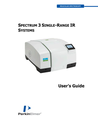
  • 1. SPECTRUM 3 SINGLE-RANGE IR SYSTEMS User’s Guide MOLECULAR SPECTROSCOPY
  • 2. Release History Part Number Release Publication Date L1050110 B June 2020 Any comments about the documentation for this product should be addressed to: User Assistance PerkinElmer Ltd Chalfont Road Seer Green Beaconsfield Bucks HP9 2FX United Kingdom Or emailed to: IRTechSupport@perkinelmer.com Notices The information contained in this document is subject to change without notice. Except as specifically set forth in its terms and conditions of sale, PerkinElmer makes no warranty of any kind with regard to this document, including, but not limited to, the implied warranties of merchantability and fitness for a particular purpose. PerkinElmer shall not be liable for errors contained herein for incidental consequential damages in connection with furnishing, performance or use of this material. Copyright Information This document contains proprietary information that is protected by copyright. All rights are reserved. No part of this publication may be reproduced in any form whatsoever or translated into any language without the prior, written permission of PerkinElmer, Inc. Copyright © 2020 PerkinElmer, Inc. Produced in the United Kingdom. Trademarks Registered names, trademarks, etc. used in this document, even when not specifically marked as such, are protected by law. PerkinElmer is a registered trademark of PerkinElmer, Inc. Spectrum IR, Spotlight, AssureID and Spectrum 3 are trademarks of PerkinElmer, Inc.
  • 3. Contents Introduction...............................................................................................5 About This Manual ............................................................................................ 6 Conventions Used in this Manual........................................................................ 7 Notes, Cautions and Warnings..................................................................... 7 Warnings and Safety Information ...........................................................11 Safety Summary...............................................................................................12 General Safety .................................................................................................13 Location and Ventilation ...................................................................................14 To allow for adequate cooling ....................................................................14 To allow any nitrogen used to disperse .......................................................14 Use of flammable solvents and samples ......................................................15 Electrical Safety ...............................................................................................17 Laser Safety Regulations...................................................................................18 Radiation Hazards and their Classification ..........................................................19 Laser radiation ..........................................................................................19 Radiation emitted by an NIR source............................................................19 Labels .............................................................................................................20 Warning Signs on the Instrument......................................................................21 EMC Compliance ..............................................................................................22 European EMC Directive.............................................................................22 FCC rules and regulations...........................................................................22 Precautions when operating .......................................................................22 An Overview of the Spectrum 3 Single-Range Spectrometers ................23 A Guided Tour of the Spectrum 3 Single-Range Spectrometers ...........................24 Optical system...........................................................................................25 Top panel controls.....................................................................................26 The sample compartment ..........................................................................26 Internal accessories...................................................................................28 External accessories...................................................................................29 The Spotlight 400 Series Imaging System ...................................................30 Power switch and communications ports .....................................................30 Accessories for the Spectrum 3 Spectrometer ....................................................31 Spectrum 3 Systems Upgrades..........................................................................33 Unpacking and Installation......................................................................35 Requirements ..................................................................................................36 Electrical requirements...............................................................................36 Environment..............................................................................................36 Unpacking the spectrometer .............................................................................37 Opening the shipping container ..................................................................37 The Desiccant Indicator....................................................................................39 Connecting up the Spectrometer.......................................................................40 Connecting to the PC .................................................................................40 Other connectors.......................................................................................41 Connecting the spectrometer to the electrical supply ...................................42 Installing the Instrument in the Software...........................................................44 Installing the software ...............................................................................44 The Instrument Install Wizard ....................................................................44 Using the Spectrometer with Spectrum IR..............................................45 Basics of Software Control ................................................................................46 Starting Spectrum IR software....................................................................46 Scanning samples......................................................................................47 Working with the instrument display and buttons ........................................48 Changing the beampath.............................................................................49 Using the Spectrum IR on-screen Help system ............................................50 Atmospheric (CO2/H2O) Suppression..................................................................51 What is atmospheric suppression? ..............................................................51
  • 4. What does atmospheric suppression do? .................................................... 51 AVI Correction................................................................................................. 53 What is AVI correction? ............................................................................. 53 What does AVI correction do?.................................................................... 54 Quality Checks................................................................................................. 55 What are Quality Checks?.......................................................................... 55 What do Quality Checks do? ...................................................................... 55 Routine Maintenance ...............................................................................57 Cleaning the Spectrometer ............................................................................... 58 Cleaning the display .................................................................................. 58 Moving the Spectrometer ................................................................................. 59 Condensation............................................................................................ 60 The Desiccant Indicator in Detail ...................................................................... 61 Changing the Desiccant.................................................................................... 62 Renewing the instrument desiccant............................................................ 63 Installing rechargeable desiccant in the instrument ..................................... 64 Purging the Spectrometer ................................................................................ 65 Changing the External Fuse.............................................................................. 68 Cooling the MCT Detector (If Fitted) ................................................................. 70 Advanced Maintenance ............................................................................73 Opening the Main Cover................................................................................... 74 Replacing a Source .......................................................................................... 78 Replacing the Beamsplitter............................................................................... 81 Installing/Replacing Beam Port and Sample Compartment Windows ................... 83 Installing Filters in the Filter Wheel................................................................... 85 Replacing the Laser and Power Supply.............................................................. 89 Replacing the HeNe laser........................................................................... 89 Appendices...............................................................................................95 Appendix 1: Changing the Sample Area Accessory............................................. 96 Appendix 2: Instrument Self-Checks ................................................................. 98 Appendix 3: Instrument Performance Validation .............................................. 100 Appendix 4: Decontamination and Cleaning..................................................... 101 Appendix 5: WEEE Instructions for PerkinElmer Products ................................. 102 Index............................................................................................................ 103
  • 6. 6 . Spectrum 3 Single-Range IR Systems User's Guide About This Manual This manual contains the following sections: • Introduction • Warnings and Safety Information • An Overview of the Spectrum 3 Single-Range IR Spectrometers • Unpacking and Installation • Using the Spectrometer with Spectrum • Routine Maintenance • Advanced Maintenance • Appendices For further information on collecting, viewing and processing spectra using Spectrum software, refer to the help file that you can access from the Help menu, or by clicking Help on a dialog. The Help menu also includes links to on-screen tutorials. NOTE: This manual shows details for using your instrument with the Spectrum software package (version 10.7 or later). If you have Spectrum ES or AssureID software, please refer to the Administrator’s Guide for your software which can be found on the Software USB, or refer to the on-screen Help.
  • 7. Introduction . 7 Conventions Used in this Manual Normal text is used to provide information and instructions. Bold text refers to text that is displayed on the screen. UPPERCASE text, for example ENTER or ALT, refers to keys on the PC keyboard. '+' is used to show that you have to press two keys at the same time, for example, ALT+F. All eight-digit numbers are PerkinElmer part numbers unless stated otherwise. The term “instrument” refers to a Spectrum 3 infrared spectrometer, and any sampling accessory fitted. Spectrum 3 Single-Range spectrometer refers to the Spectrum 3 FT-MIR and FT-NIR spectrometers. Notes, Cautions and Warnings Three terms, in the following standard formats, are also used to highlight special circumstances and warnings. NOTE: A note indicates additional, significant information that is provided with some procedures.
  • 8. 8 . Spectrum 3 Single-Range IR Systems User's Guide CAUTION We use the term CAUTION to inform you about situations that could result in serious damage to the instrument or other equipment. Details about these circumstances are in a box like this one. Caution (Achtung) Bedeutet, daß die genannte Anleitung genau befolgt werden muß, um einen Geräteschaden zu vermeiden. Caution (Bemærk) Dette betyder, at den nævnte vejledning skal overholdes nøje for at undgå en beskadigelse af apparatet. Caution (Advertencia) Utilizamos el término CAUTION (ADVERTENCIA) para advertir sobre situaciones que pueden provocar averías graves en este equipo o en otros. En recuadros éste se proporciona información sobre este tipo de circunstancias. Caution (Attention) Nous utilisons le terme CAUTION (ATTENTION) pour signaler les situations susceptibles de provoquer de graves détériorations de l'instrument ou d'autre matériel. Les détails sur ces circonstances figurent dans un encadré semblable à celui-ci. Caution (Attenzione) Con il termine CAUTION (ATTENZIONE) vengono segnalate situazioni che potrebbero arrecare gravi danni allo strumento o ad altra apparecchiatura. Troverete informazioni su tali circostanze in un riquadro come questo. Caution (Opgelet) Betekent dat de genoemde handleiding nauwkeurig moet worden opgevolgd, om beschadiging van het instrument te voorkomen. Caution (Atenção) Significa que a instrução referida tem de ser respeitada para evitar a danificação do aparelho. Caution (小心) 我们使用“小心”这一术语来通知您有关可能会对 本仪器或其它设备造成严重损害的情况。 有关这些情况的详细信息可在此类方框中找到。 Caution (注意) 分光器や他の機材等に深刻なダメージを与える恐れがある場合は、 この様なボックスの中に表示しています。
  • 9. Introduction . 9 WARNING We use the term WARNING to inform you about situations that could result in personal injury to yourself or other persons. Details about these circumstances are in a box like this one. Warning (Warnung) Bedeutet, daß es bei Nichtbeachten der genannten Anweisung zu einer Verletzung des Benutzers kommen kann. Warning (Advarsel) Betyder, at brugeren kan blive kvæstet, hvis anvisningen ikke overholdes. Warning (Peligro) Utilizamos el término WARNING (PELIGRO) para informarle sobre situaciones que pueden provocar daños personales a usted o a otras personas. En los recuadros como éste se proporciona información sobre este tipo de circunstancias. Warning (Danger) Nous utilisons la formule WARNING (DANGER) pour avertir des situations pouvant occasionner des dommages corporels à l'utilisateur ou à d'autres personnes. Les détails sur ces circonstances sont données dans un encadré semblable à celui-ci. Warning (Pericolo) Con il termine WARNING (PERICOLO) vengono segnalate situazioni che potrebbero provocare incidenti alle persone. Troverete informazioni su tali circostanze in un riquadro come questo. Warning (Waarschuwing) Betekent dat, wanneer de genoemde aanwijzing niet in acht wordt genomen, dit kan leiden tot verwondingen van de gebruiker. Warning (Aviso) Significa que a não observância da instrução referida poderá causar um ferimento ao usuário. Warning (警告) 我们使用“警告”这一术语来通知您有关可能会对您自己或他人造成人 身伤害的情况。 有关这些情况的详细信息可在此类方框中找到。 Warning (警告) 使用者及びその他周辺に危害が及ぶ恐れがある場合は、 この様なボックスの中に注意事項が表示されています。
  • 10. 10 . Spectrum 3 Single-Range IR Systems User's Guide
  • 12. 12 . Spectrum 3 Single-Range IR Systems User's Guide Safety Summary The Spectrum 3 spectrometers have been designed to comply with a wide variety of international standards governing the safety of laboratory equipment. In routine use, the instruments pose virtually no risk to you. If you take some simple, common-sense precautions, you can make sure that you maintain the continued safe operation of your instrument: DO make sure that the instrument is properly connected to the electrical supply; in particular make sure that the ground (earth) is securely connected. DO disconnect the electrical power cable before opening the main cover of the instrument. DO keep the instrument dry. Avoid spilling liquid into the instrument. Clean all external spills immediately. If anything that is spilled enters the main body of the instrument, switch off the power and contact a PerkinElmer Service Engineer. DO NOT stare into the internal laser beam under the instrument cover. The instrument contains a low power laser which may be visible (red) or invisible depending on the type of laser installed; momentary exposure to the beam is not dangerous, but deliberate, direct viewing of the beam along its axis could damage your eye. DO NOT use a flammable gas to purge the instrument. The instrument contains a hot source, and a fire or explosion will result. Only use clean, dry, oil-free nitrogen or air to purge the instrument. DO read the more detailed information on warnings and safety in the following pages to ensure the safe operation of the instrument.
  • 13. Warnings and Safety Information . 13 General Safety The Spectrum 3 spectrometers have been designed and tested in accordance with PerkinElmer specifications and in accordance with the safety requirements of the International Electrotechnical Commission (IEC). The instruments conform to IEC publication 61010-1 (“Safety requirements for electrical equipment for measurement, control, and laboratory use”) as it applies to IEC Class 1 (earthed) appliances and therefore meets the requirements of EU Low Voltage Directive 2014/35/EU. If the instrument is used in a manner not specified by the manufacturer, the protection provided by the instrument may be impaired. Only use the instrument indoors and under the following conditions: Temperature 15 °C to 35 °C Relative Humidity 80% maximum (non-condensing) If possible, avoid any adjustment, maintenance and repair of the opened, operating instrument. If any adjustment, maintenance and repair of the opened, operating instrument is necessary, this must only be done by a skilled person who is aware of the hazard involved. Whenever it is likely that the instrument is unsafe, make it inoperative. The instrument may be unsafe if it: • Shows visible damage • Fails to perform the intended measurement • Has been subjected to prolonged storage in unfavorable conditions • Has been subjected to severe transport stresses. WARNING AVERTISSEMENT The protection provided by this equipment may be impaired if the equipment is used in a manner not specified by PerkinElmer. La protection fournie par cet équipement risque d'être moins efficace si l'équipement fait l'objet d'une utilisation différente de celle mentionnée par PerkinElmer. The instrument has been designed to be safe under the following environmental conditions: • Indoor use • Altitude up to 2000 m (above mean sea level) • Ambient temperatures of 5 °C to 40 °C • A maximum ambient relative humidity of 80% for temperatures up to 31 °C, decreasing linearly to 50% relative humidity at 40 °C • Mains supply fluctuations not exceeding ±10% of the nominal voltage.
  • 14. 14 . Spectrum 3 Single-Range IR Systems User's Guide Location and Ventilation WARNING AVERTISSEMENT Make sure that the switch at the electrical supply inlet on the rear of the instrument is not obstructed. Assurez-vous que l’interrupteur de l’alimentation électrique situé à l’arrière de l’instrument n’est pas obstrué. To allow for adequate cooling Do not locate the instrument near to room heating equipment, for example, central heating radiators. During operation, there should be a minimum gap of: • 15 cm (6 inches) between any surface and the cooling louvers at the rear of the instrument. • 7 cm (3 inches) between the instrument and adjacent equipment. • 45 cm (18 inches) between any surface and the top surface of the closed sample area lid (to allow for the lid to be opened fully). To allow any nitrogen used to disperse WARNING AVERTISSEMENT Do not site the instrument in a poorly ventilated area if nitrogen will be used as a purge gas, or if liquid nitrogen will be used to cool a detector. Oxygen depletion in an enclosed space does not trigger a gasping reflex, and errors of judgment, confusion, or unconsciousness can occur in seconds and without warning. Ne placez pas l’instrument dans un endroit mal ventilé si de l’azote doit être utilisé comme gaz de purge, ou si de l’azote liquide doit être utilisé pour refroidir un détecteur. L’appauvrissement en oxygène d’un espace clos ne déclenche pas de réflexe de halètement, et des erreurs de jugement, de la confusion ou une perte de conscience peuvent survenir en quelques secondes sans prévenir. The spectrometer includes a coupling that enables the instrument body, and another coupling that enables the sample compartment, to be purged using clean, dry, oil-free air or nitrogen. The recommended flow rate to each connector is 10 l/min, and both the instrument and the sample compartment vent to their surroundings. If the instrument is fitted with an MCT detector, this is cooled using liquid nitrogen. A risk assessment should include personal protection protocols, and proper actions in the event of accidental spillage. 1 l (2 US pints) of liquid nitrogen evolves to 700 l (approximately 25 cubic feet) of nitrogen gas, and the cold vapor can pool at floor level.
  • 15. Warnings and Safety Information . 15 Use of flammable solvents and samples WARNING AVERTISSEMENT The instrument contains a hot source and contact with flammable vapors may cause an explosion. When working with flammable solvents or samples, particularly during unattended operation with flow-cells, it is recommended that the instrument optics area should be continuously purged with dry air or nitrogen to maintain a positive pressure and prevent flammable vapor from entering the instrument. L’instrument contient une source chaude. Le contact avec des vapeurs inflammables peut provoquer une explosion. Lorsque vous travaillez avec des solvants ou des échantillons inflammables, en particulier lors d’opérations sans surveillance avec des cuves à circulation, il est recommandé de purger en continu la zone des optiques de l’instrument avec de l’air sec ou de l’azote afin de maintenir une pression positive et d’éviter aux vapeurs inflammables de pénétrer dans l’instrument. WARNING AVERTISSEMENT If flammable solvents or samples are spilled on the instrument and there is any possibility that they have entered the interior (by coming into contact with cover gaskets, for example) then the instrument must be switched off immediately and disconnected from the power supply. The optics area should then be thoroughly purged with dry air or nitrogen, or the main cover should be opened to thoroughly ventilate the optics area before proceeding. Si des solvants ou échantillons inflammables sont renversés sur l’instrument et s’il existe une possibilité qu’ils aient pénétré à l’intérieur de l’instrument (en entrant en contact avec les joints du couvercle par exemple), l’instrument doit être éteint immédiatement et débranché de l’alimentation électrique. La zone contenant les optiques doit ensuite être purgée à fond avec de l’air sec ou de l’azote, ou le couvercle principal doit être ouvert pour bien ventiler la zone des optiques avant de continuer. WARNING AVERTISSEMENT Flammable solvents or samples should not be stored on or near the instrument. Handling of such materials during preparation should be performed in a safe area away from the instrument such as a fume cabinet. Des solvants ou des échantillons inflammables ne doivent pas être stockés sur ou à proximité de l’instrument. La manipulation de ces matières pendant une préparation doit être effectuée dans un endroit sûr, loin de l’instrument, tel qu’une hotte.
  • 16. 16 . Spectrum 3 Single-Range IR Systems User's Guide WARNING AVERTISSEMENT Do not use a flammable gas to purge the Spectrum 3 instruments. Use only clean, dry, oil-free nitrogen or air. N’utilisez pas de gaz inflammables pour purger les spectromètres Spectrum 3. Utilisez uniquement de l’azote ou de l’air propre, sec et exempt d’huile pour purger l’instrument.
  • 17. Warnings and Safety Information . 17 Electrical Safety • Connect the instrument to a power supply line that includes a switch or other means of disconnection from the electricity supply. • Only plug the instrument into an electricity-supply socket that is provided with a protective earth connection. • When fuses need replacing, use only those with the required current rating and of the specified type. Do not use makeshift fuses and do not short-circuit fuse holders. • When the instrument is connected to its electricity supply, terminals may be live and the removal of covers other than those which can be removed by hand is likely to expose live parts. • Capacitors inside the instrument may still be charged even if the instrument has been disconnected from all voltage sources. • The instrument must be disconnected from all voltage sources before it is opened for any adjustment, replacement, maintenance or repair. WARNING AVERTISSEMENT Any interruption of the protective conductor (earth ground) inside or outside the instrument or disconnection of the protective conductor terminal is likely to make the instrument dangerous. Toute interruption du conducteur de protection (mise à la terre) à l'intérieur ou à l'extérieur de l'instrument ou toute déconnexion de la borne du conducteur de protection risque de rendre l'instrument dangereux. The instrument has an IEC Insulation Class I rating for external circuits – only connect other equipment that meets the requirements of IEC 61010-1, IEC 60950 or equivalent standards.
  • 18. 18 . Spectrum 3 Single-Range IR Systems User's Guide Laser Safety Regulations The Spectrum 3 spectrometers are Class 1 laser products as defined by IEC 60825-1. The optical module contains: a Class 2 Helium Neon (HeNe) laser, which emits visible, continuous wave radiation at a wavelength of 633 nm and has a maximum output power of 1 mW OR a Class 1 diode laser, which emits invisible, continuous wave radiation at a wavelength of 850 nm and has a maximum output power of 0.6 mW. Some diffuse laser radiation, within Class 1 limits, emerges from: • The window in the left side of the sample compartment when an internal beam path is selected. • An external beam port when the port cover is removed, no accessory is fitted at the port, and the beam path to the port is selected. The laser is automatically shut down when the main cover of the instrument is raised. The instrument complies with the following laser safety regulations: 1. 21 CFR Part 1040.10 and 1040.11 except for deviations pursuant to Laser Notice No. 50 dated 24 June 2007. Administered by the Center for Devices and Radiological Health, U.S. Department of Health and Human Services. 2. European Standard EN 60825-1:2014 – “Safety of laser products – Part 1: Equipment classification and requirements”. WARNING AVERTISSEMENT Do not stare into any laser beam. Staring into a laser beam (intrabeam viewing) can cause permanent damage to your eyes. Ne fixez pas le faisceau laser. Regarder fixement un faisceau laser (visualisation intrafaisceaux) peut causer des dommages permanents à vos yeux. WARNING AVERTISSEMENT Do not attempt to override or modify the interlock system. Use of controls or adjustments or performance of procedures other than those specified herein may result in hazardous radiation exposure. N’essayez pas de remplacer ou de modifier le système de verrouillage. L’utilisation de commandes ou de réglages ou l’exécution de procédures autres que celles spécifiées dans le présent document peut entraîner une exposition dangereuse à des rayonnements.
  • 19. Warnings and Safety Information . 19 Radiation Hazards and their Classification Laser radiation Indirect observation of the laser beam radiation in the optical path is not hazardous. Directly viewing the laser beam along its axis (allowing the laser beam radiation to pass into the eye) can be hazardous, depending upon the power of the beam, the length of time that the eye is exposed to the beam and the optical efficiency of the exposed eye. Direct viewing of a laser beam along its axis is termed intrabeam viewing. Protection of the eye during accidental, momentary intrabeam viewing of a Class 2 HeNe laser beam is normally given by the eye’s aversion response, including the blink reflex, which limits exposure of the eye to less than 0.25 seconds. There is greater potential for accidental intrabeam viewing of the Class 1 diode laser because the beam is invisible. When this laser is installed in the spectrometer, avoid switching on power to the laser while the instrument covers are raised (this requires disabling of the safety controls and should only be performed by PerkinElmer service representatives in the event of a problem with the instrument). Class 1 levels of laser radiation are not considered to be hazardous. Radiation emitted by an NIR source Your Spectrum 3 instrument can be fitted with an NIR (near-infrared) source. The quartz halogen bulb, which produces the near-infrared beam, emits ultraviolet, visible and infrared radiation. The majority of this radiation is in the infrared region. Do not stare into the beam produced by this bulb. Measurements of the infrared radiation emitted from the sample area show that exposure limits recommended by the American Conference of Governmental Industrial Hygienists (ACGIH) and International Commission on Non-Ionizing Radiation Protection (ICNIRP) will not be exceeded during normal operation.
  • 20. 20 . Spectrum 3 Single-Range IR Systems User's Guide Labels The product identification label is on the front of the instrument. Other labels are fixed to the Spectrum 3 spectrometer in the locations shown in Figure 1 and Figure 2: Figure 1 Labels (rear of instrument) NOTE: The label with a crossed-out wheeled bin symbol and a rectangular bar indicates that the product is covered by the Waste Electrical and Electronic Equipment (WEEE) Directive. Refer to Appendix 5: WEEE Instructions for PerkinElmer Products on page 102. Figure 2 Labels (sample compartment) NOTE: There is a second copy of the CAUTION label inside the sample compartment cover. Serial number, part number and date of manufacture
  • 21. Warnings and Safety Information . 21 Warning Signs on the Instrument Caution, hot surface. Attention, surface chaude. Caution, risk of electric shock. Attention, risque de choc électrique Caution, laser radiation hazard. Attention, risque de rayonnement laser. Caution, risk of danger. Documentation must be consulted to determine the nature of the potential hazard and any actions which have to be taken. Attention, danger potentiel. Consultez la documentation afin de déterminer la nature du danger potentiel et les mesures à prendre.
  • 22. 22 . Spectrum 3 Single-Range IR Systems User's Guide EMC Compliance European EMC Directive The Spectrum 3 spectrometers have been designed and tested to meet the requirements of the EU EMC Directive 2014/30/EU. The product is certified with respect to its immunity to radiated radio frequencies as described in EN 61000-4-3, subject to the following restriction: When the instrument is subjected to a test field of 10 V/m over the frequency range 80– 1000 MHz, with 80% amplitude modulation at 1 kHz, noise spikes may be observed at the spectral wavenumbers having a modulation frequency of 1 kHz and its harmonics. Outside a window of 150 Hz half-width, noise due to these spikes shall not exceed 20% of the instrument response (black-body) peak in an open beam configuration. FCC rules and regulations These products are classified as digital devices used exclusively as industrial, commercial, or medical test equipment. They are exempt from the technical standards specified in Part 15 of the FCC Rules and Regulations, based on Section 15.103(c). Precautions when operating In some instances, the presence of a cellular (mobile) phone close to the spectrometer can cause noise spikes in the spectral data recorded by the instrument. This can be avoided by keeping these devices at least 30 cm away from the spectrometer when data is being collected.
  • 23. An Overview of the Spectrum 3 Single-Range Spectrometers
  • 24. 24 . Spectrum 3 Single-Range IR Systems User's Guide A Guided Tour of the Spectrum 3 Single-Range Spectrometers PerkinElmer Spectrum 3 Single-Range spectrometers are bench-top FT-IR instruments (Figure 3). Figure 3 Spectrum 3 Single-Range spectrometer • Spectrum 3 FT-MIR spectrometers: – The optical system enables you to collect data over a total range of 8300 to 350 cm−1 with a best resolution of 0.4 cm−1 . – A LiTaO3 MIR detector. – Optional gold optics. – Optional MCT detector. • Spectrum 3 Performance Pack Systems FT-MIR spectrometers: – The optical system enables you to collect data over a total range of 8300 to 350 cm−1 with a best resolution of 0.4 cm−1 . – A DTGS (deuterated triglycine sulfate) MIR detector as standard for enhanced signal-to-noise. – Optional gold optics. – Optional MCT detector. • Spectrum 3 Extended Range Performance Pack FT-MIR spectrometers: – The optical system with CsI beamsplitter enables you to collect data over a total range of 7800 to 225 cm−1 with a best resolution of 0.4 cm−1 . – A DTGS (deuterated triglycine sulfate) MIR detector as standard. – Optional gold optics. – Optional MCT detector. • Spectrum 3 FT-NIR spectrometers: – The optical system enables you to collect data over a total range of 14700 to 2000 cm−1 with a best resolution of 0.5 cm−1 . – An NIR DTGS (deuterated triglycine sulfate) detector. – Gold optics as standard.
  • 25. An Overview of the Spectrum 3 Single-Range Spectrometers . 25 The instrument can operate in ratio, single-beam, or interferogram mode. The instrument is connected to a PC, either point-to-point or over a network. The Spectrum IR software package supplied enables you to control the instrument and to manipulate the spectra that you collect. Optical system The optical system is under the main cover of the instrument. Usually the main cover of the instrument is closed, but to perform most maintenance tasks, the cover has to be open. When you do this, a safety interlock automatically switches off the power. Nevertheless, the instrument should be disconnected from the mains before opening the main cover for maintenance. Consistent, reliable performance is achieved by having few adjustable parts, and by extensive insulation of the optical system from the effects of humidity and vibration. Stability of the optical system The entire optical system is purged and sealed at the factory. A supply of desiccant placed within the system removes any water vapor and carbon dioxide that may enter. A desiccant indicator is fitted in the top cover, which warns you when the desiccant needs changing (an internal humidity sensor is available as an option). In Spectrum 3 Single-Range FT-MIR spectrometers, KBr or CsI windows separate the sample compartment from the purged optical system. For FT-NIR spectrometers, these windows are CaF2. NOTE: Before you select the MCT detector (optional) in Spectrum IR software, fit one of the attenuators supplied (Attenuator Set – L1160560) to the window to the right of the sample compartment to prevent the detector from overloading. See Installing/Replacing Beam Port and Sample Compartment Windows on page 83 for more information. You can purge the sample compartment with clean, dry, oil-free air or nitrogen. Either one removes water vapor; however, nitrogen is preferable because it also removes atmospheric carbon dioxide. WARNING AVERTISSEMENT Do not use a flammable gas to purge the Spectrum 3 instruments. The instrument contains a hot source, and a fire or explosion will result. Only use clean, dry, oil-free nitrogen or air to purge the instrument. N’utilisez pas de gaz inflammables pour purger les spectromètres Spectrum 3. L’instrument contient une source chaude, un incendie ou une explosion peut avoir lieu. Utilisez uniquement de l’azote ou de l’air propre, sec et exempt d’huile pour purger l’instrument. The optics are kinematically mounted to ensure accurate positioning and to make them rugged. The interferometer is enclosed and mounted on anti-vibration mounts to guard against air and bench borne disruptions. The interferometer uses very low-friction point bearings and a frictionless electromagnetic drive to ensure long life.
  • 26. 26 . Spectrum 3 Single-Range IR Systems User's Guide Top panel controls The display on the front right of the top of your instrument (Figure 4) has three purposes: • To display messages generated by the instrument’s firmware, such as those that monitor initialization and diagnostics when the instrument is first switched on. • To display prompts and other messages which allow you start and stop data collection at the spectrometer. • To display the results from data processing steps performed during an analysis. The functions of the buttons on the display screen and the display prompts and other messages are controlled by the Spectrum IR software. The button functions change depending on the screen prompts. Figure 4 Spectrum 3 top panel controls Figure 5 Spectrum 3 initial display screen The sample compartment The instrument has a large, purgeable sample compartment (Figure 6) located at the front of the instrument. Display Buttons
  • 27. An Overview of the Spectrum 3 Single-Range Spectrometers . 27 Figure 6 Spectrum 3 sample compartment CAUTION ATTENTION Spectrum 3 FT-MIR spectrometers are fitted with sample compartment windows that are composed of KBr or CsI that, although coated, can be damaged by high levels of humidity. If you spill a liquid in the sample compartment, wipe it up quickly. When working with water-based samples open to the air, either purge the sample compartment or leave the cover open. Les spectromètres FT-MIR Spectrum 3 sont équipés de fenêtres de compartiment d’échantillons composés de KBr ou Csl, qui, bien que revêtues, peuvent être endommagées lorsque les niveaux d’humidité sont élevés. Si vous renversez un liquide dans le compartiment d’échantillons, essuyez- le rapidement. Lorsque vous travaillez avec des échantillons à base d’eau ouverts à l’air, purgez le compartiment d’échantillons ou laissez le couvercle ouvert. Sample compartment lid Baseplate
  • 28. 28 . Spectrum 3 Single-Range IR Systems User's Guide Open the sample compartment by lifting the cover using the recess at the front. The infrared beam enters the sample compartment through an aperture on the left. After passing through the sample, it enters the detector area through an aperture on the right side of the sample compartment. Standard sampling accessories are mounted on a baseplate. The standard baseplate includes a sample holder located by a knurled screw. Internal accessories A wide range of optional MIR or NIR accessories, such as the Universal ATR accessory, fit in the sample compartment (Figure 7). Figure 7 Spectrum 3 with Universal ATR accessory It is easy to remove an internal accessory and to replace it with another. See Appendix 1: Changing the Sample Area Accessory on page 96. The instrument identifies the type of accessory fitted using a coded connector on its baseplate that plugs into a socket on the rear wall of the sample compartment. CAUTION ATTENTION For the Spectrum 3 FT-MIR, a relative humidity higher than 80% (or 45% if your instrument is fitted with CsI optics) can damage the windows of the sample compartment. If you expect the humidity to exceed 80% (or 45% if your instrument is fitted with CsI optics), continually purge or desiccate the sample compartment. Spectrum 3 FT-NIR spectrometers are fitted with sample compartment windows that are composed of CaF2, which is relatively resistant to humidity. Pour le Spectrum 3 FT-MIR, une humidité relative supérieure à 80 % (ou 45 % si l’instrument est équipé d’optiques Csl) peut endommager les fenêtres du compartiment d’échantillons. Si vous prévoyez une humidité supérieure à 80 % (ou 45 % si votre instrument est équipé d’optiques Csl), purgez ou desséchez en continu le compartiment d’échantillons. Les spectromètres FT-NIR Spectrum 3 sont équipés de fenêtres de compartiment d’échantillons composé de CaF2, relativement résistant à l’humidité.
  • 29. An Overview of the Spectrum 3 Single-Range Spectrometers . 29 External accessories The external beam port on the right side of the instrument is used, for example, with the optional External Near-Infrared Accessory (External NIRA). Spectrum IR software enables you to switch the instrument between this external accessory and another accessory fitted in the sample compartment. Figure 8 External beam port on Spectrum 3 NOTE: To use your instrument with an external accessory, you require the optional External Beam Pack. If you did not purchase the External Beam Pack with your spectrometer, it is available as a field-fitted upgrade (L1280248). For information about removing or refitting an external accessory, refer to its User’s Guide, which is distributed on the IR Hardware Documentation USB as a .pdf file. For information about moving the instrument, see Moving the Spectrometer on page 59. CAUTION ATTENTION Do not attempt to remove the external accessory bracket mounted within the handhold on the right of the instrument or to transfer the bracket to another spectrometer. The external accessory bracket is fitted by a PerkinElmer Service Engineer, along with any other internal components that may be required. N’essayez pas de retirer le support d’accessoires externe monté dans la poignée sur la droite de l’instrument ou de transférer le support vers un autre spectromètre. Le support d’accessoires externe est installé par un ingénieur de maintenance PerkinElmer, ainsi que tous les autres composants internes qui peuvent être nécessaires. CAUTION ATTENTION Do not attempt to lift the instrument, or to move it to another location, when an external accessory is attached. The optical alignment of the accessory may be disturbed. N’essayez pas de soulever l’instrument ou de le déplacer à un autre endroit lorsqu’un accessoire externe est fixé. L’alignement optique de l’accessoire peut être perturbé. External beam port
  • 30. 30 . Spectrum 3 Single-Range IR Systems User's Guide The Spotlight 400 Series Imaging System The external port on the left side of the instrument is used with the Spotlight 400 Imaging System (Figure 9) and SpectrumIMAGE software. Figure 9 Spotlight 400 Series Imaging System NOTE: To use your instrument with a microscope, you require the optional External Beam Pack. If you did not purchase the External Beam Pack with your spectrometer, it is available as a field-fitted upgrade (L1280248). Power switch and communications ports The power switch, AC power cable connector, and communications ports are on the rear of the instrument. The power switch is marked I/O (on/off). NOTE: It can take the instrument about two hours to equilibrate when switched on after being switched off overnight. To save time, we suggest that you leave the instrument switched on at all times.
  • 31. An Overview of the Spectrum 3 Single-Range Spectrometers . 31 Accessories for the Spectrum 3 Spectrometer A wide range of optional accessories, such as the NIR Fiber Optic Probe (Figure 10), fit in the sample compartment. In addition, a number of external accessories are available, including the External NIRA. An external accessory can be fitted in conjunction with another internal accessory. Figure 10 Spectrum 3 spectrometer with NIR Fiber Optic Probe accessory There is a range of specialized sampling accessories available for the Spectrum 3 instruments, as shown in Table 1. Table 1 Sampling accessories for the Spectrum 3 instruments Accessory Type MIR NIR Sample Shuttle Internal Yes Yes Horizontal ATR Internal Yes n/a Universal ATR Internal Yes n/a Diffuse Reflectance Internal Yes n/a NIRA Internal (limited utility) Yes External NIRA External (limited utility) Yes NIR Fiber Optic Probe Internal (limited utility) Yes TL 8000 EGA System (TG-IR) – Yes Yes EGA 4000 Internal Yes Yes Heated Transmission Module Internal Yes Yes
  • 32. 32 . Spectrum 3 Single-Range IR Systems User's Guide Accessory Type MIR NIR General Purpose Optical Bench (GPOB) and External MCT Detector* External Yes Yes General Purpose Optical Bench (GPOB) and External LiTaO3 Detector* External Yes Yes * For more details of the GPOB options, contact your PerkinElmer Sales Representative. Further information about the use of these accessories can be found on the IR Hardware Documentation USB.
  • 33. An Overview of the Spectrum 3 Single-Range Spectrometers . 33 Spectrum 3 Systems Upgrades The Spectrum 3 systems are designed to be flexible, upgradable instruments, including the ability to upgrade from a single-range to a dual- or tri-range instrument. The upgrades available for the Spectrum 3 Single-Range System are listed in Table 2. Table 2 Spectrum 3 Single-Range Systems Upgrades Part Number Description L1280247 Performance Pack Upgrade – DTGS detector upgrade L1280248 External Pack Beam Upgrade – Microscope, GPOB, NIRA and external beam input port ready The kit contains KBr windows, but other windows are available. Ask your PerkinElmer Customer Service Representative for details L1370157 Single-Range FT-MIR to Dual-Range FT-MIR/FT-NIR upgrade L1370158 Single-Range FT-MIR to Dual-Range FT-MIR/FT-FIR upgrade L1370159 Single-Range FT-NIR to Dual-Range FT-MIR/FT-NIR upgrade L1370160 Single-Range FT-MIR to Tri-Range FT-NIR/FT-MIR/FT-FIR upgrade L1280249 Narrow band 1 mm MCT FT-MIR Second Detector (adds an MCT detector in the second detector position) FT-MIR instruments only L1280250 Medium band 1 mm MCT FT-MIR Second Detector (adds an MCT detector in the second detector position) FT-MIR instruments only L1280251 Wide band 1 mm MCT FT-MIR Second Detector (adds an MCT detector in the second detector position) FT-MIR instruments only L1250477 ZnSe Window Upgrade Kit (optional ZnSe window for Single-Range FT-MIR instruments) L1370112 FastScan Module L1200391 Electronic Humidity Sensor L1370144 Diode Laser Upgrade Kit L1370143 HeNe Laser Upgrade Kit
  • 34. 34 . Spectrum 3 Single-Range IR Systems User's Guide
  • 36. 36 . Spectrum 3 Single-Range IR Systems User's Guide Requirements NOTE: Read the warnings and safety information at the start of this manual before you install the instrument. They contain important information. Electrical requirements The Spectrum 3 Single-Range spectrometers can operate on electricity supplies of 50 or 60 Hz and in the 100 V to 230 V range without any adjustment. The nominal power consumption of the instrument is 120 VA. The line supply must be within 10% of the nominal voltage. If possible, do not connect the instrument to circuits that have heavy-duty equipment connected, such as large motors. If possible, do not use photocopiers, discharge lamps, radio transmitters, and other equipment with large or frequent transient loads on the same supply circuit. The primary fuse (2 AT, 250 V) is in the drawer on the rear of the instrument next to the mains inlet: the spare fuse is in the same drawer. The primary fuse is connected in the live line. Environment To obtain the best performance from your instrument: • Place the instrument in an environment that is relatively dust-free. • Make sure that the bench top is free from vibration or mechanical shocks. • Do not place the instrument or the PC near to room-heating equipment, such as central-heating radiators. • Do not position the instrument in direct sunlight, as this may cause overheating. • Leave at least 15 cm (6 inches) from any surface and the cooling louvers at the rear of the instrument. • Leave at least 7 cm (3 inches) from any vertical obstacle to the sides of the instrument, to permit an adequate flow of cooling air. • Make sure that there are no overhanging shelves, and no water pipes or faucets that could leak onto the instrument. • The area near the PC must be free of strong magnetic fields, direct sunlight, and heating or cooling units or ducts. The instrument has been designed for indoor use and operates correctly under the following conditions: Ambient temperature 15 °C to 35 °C Ambient relative humidity 80% maximum (non-condensing)
  • 37. Unpacking and Installation . 37 Unpacking the spectrometer WARNING AVERTISSEMENT The Spectrum 3 spectrometer is a heavy precision instrument, so two people are required for safe handling. The instrument weighs approximately 36 kg unpacked (40 kg packed) and has a lifting recess on either side. Consult the local codes of practice issued by safety advisors before attempting to lift it. Take care not to injure yourself or others, or to drop the instrument. Le spectromètre Spectrum 3 est un instrument de précision très lourd, il est donc nécessaire d’être à deux pour le manipuler en toute sécurité. L’instrument pèse environ 36 kg déballé (40 kg emballé) et dispose d’une encoche sur chaque côté pour soulever l’instrument. Consultez les codes de bonne pratique locaux émis par les responsables en charge de la sécurité avant d’essayer de le soulever. Veillez à ne pas vous blesser ou à blesser les autres, ou à ne pas faire tomber l’instrument. CAUTION ATTENTION Take great care when installing your Spectrum 3 spectrometer, and follow the procedures described in this manual. If you require assistance, contact your local PerkinElmer Service Engineer. Faites très attention lors de l’installation de votre spectromètre Spectrum 3, et suivez les procédures décrites dans ce manuel. Si vous avez besoin d’assistance, contactez votre ingénieur de maintenance PerkinElmer local. Opening the shipping container Your instrument is packed inside the box in a silver bag that protects it from condensation. The spare windows are packed as kits in separate protective containers. 1. First remove the manuals/software box, leads, and so on from the box, and check that all the following parts are present: Part Number Description MIR NIR L1202057 Polystyrene Calibration Film 1 – L1180479 NIR Performance Validation Kit – 1 04974265 Quick Release Purge Coupling 2 2 L1200466 Ethernet Crossover Cable 1 1 04790839 2 A, 250 V Time Lag Fuse 2 2
  • 38. 38 . Spectrum 3 Single-Range IR Systems User's Guide Part Number Description MIR NIR L9003693 8.0 mm Hexagonal Wrench 1 1 L1250230 Spectrum Configuration Disk 1 1 LX100961 OR LX100962 Spectrum IR Software USB OR Spectrum IR ES Software USB 1 1 L1050002 IR Hardware Documentation USB 1 1 L1240055 Cuvette Holder Assembly – 1 L1240056 Cell Holder Assembly & Disposable Cells (5) – 1 If any items are missing or damaged, contact your local PerkinElmer office. 2. Carefully remove the instrument from the shipping container, but not from the bag in which it was shipped. CAUTION ATTENTION The spectrometer must be allowed to reach the temperature of its surroundings before it is removed from the bag. This means leaving it in its packaging overnight if moved from a cold area, and for at least four hours after removal from the shipping container. Il faut laisser au spectromètre le temps d’atteindre la température ambiante avant d’être retiré de la housse. Cela signifie le laisser dans son emballage pendant la nuit s’il arrive d’une zone froide, et pendant au moins quatre heures après le retrait de la boîte d’expédition. 3. When the spectrometer has been allowed to warm to the temperature of its surroundings, remove it from the bag and place it on the bench where it is to be used. Ensure that you can reach the rear of the spectrometer to connect the cables. NOTE: Any accessories will be shipped in separate boxes.
  • 39. Unpacking and Installation . 39 The Desiccant Indicator The optical system of the spectrometer is purged at the factory. This protects the beam port windows (and, once fitted, the beamsplitters) from being damaged by humidity. Replaceable packs of desiccant keep the optics dry and free of CO2. The top panel of the instrument includes a desiccant indicator, whose sectors change sequentially from blue to pink as the desiccant becomes exhausted (Figure 11). Change the desiccant in the instrument when the sector marked 10 becomes pink, but while the sectors marked 15 and 20 are still blue. These numbers correspond to the approximate % Relative Humidity in the instrument. Refer to The Desiccant Indicator in Detail on page 61 for more information about the appropriate action to take if the sectors marked 15 and 20 are pink. Figure 11 The desiccant indicator CAUTION ATTENTION If all three sectors of the desiccant indicator are pink, then you must change the desiccant. The instrument optics may be fogged. Do not switch the instrument either ON or OFF until all sectors are blue. Si les trois secteurs de l’indicateur du dessiccant sont roses, vous devez changer le dessiccant. Les optiques de l’instrument peuvent être embuées. N’allumez pas ou n’éteignez pas l’instrument tant que tous les secteurs ne sont pas bleus. Pink Blue Blue
  • 40. 40 . Spectrum 3 Single-Range IR Systems User's Guide Connecting up the Spectrometer Connecting to the PC NOTE: To control your instrument from a PC, use the crossover cable supplied. To control your instrument over your network, use a standard Ethernet cable (not supplied). 1. Plug one end of the cable into the connector port on the right-hand side of the instrument (Figure 12). Figure 12 PC Connection port 2. Plug the other end of the cable into the network connection on your PC (if you are using the crossover cable) or network hub (if you are using a standard Ethernet cable). Connector details Description Connector Type Voltage Maximum Current 10/100 Base-T Ethernet connector. This is the standard interface between the PC and the instrument, or between a Local Area Network (LAN) and the instrument. If connecting directly from the PC to the instrument use the Category 5 UTP Crossover cable supplied. If you are connecting to your network, use a standard Ethernet cable. DO NOT USE THE CROSSOVER CABLE TO CONNECT TO YOUR NETWORK. Ethernet <5 V <100 mA PC or network connection port
  • 41. Unpacking and Installation . 41 Other connectors The communication ports for peripheral devices are shown in Figure 13. Figure 13 Communication ports Legends and icons that identify the function of each of the ports are printed on the hinge molding directly above the port. CAUTION ATTENTION Do not attempt to connect a monitor to either the EXT.R port or the MICROSCOPE port or you will cause serious damage to the instrument when it is switched on. N’essayez pas de connecter le moniteur au port EXT.R ou au port MICROSCOPE ou vous endommagerez sérieusement l’instrument lorsqu’il sera allumé. Sample area purge Instrument purge 10101 Spt. Lt. EXT.R
  • 42. 42 . Spectrum 3 Single-Range IR Systems User's Guide Connector details Icon Description Connector Type Voltages Maximum Currents 10101 Serial port. Connects a PC to the instrument using an RS232 interface cable. This connector is only used for service diagnostics or during fast scanning data acquisition with a Spotlight microscope. 9-way D-type +12 V <100 mA −12 V <100 mA General Purpose Optical Bench (GPOB). Allows synchronization between the instrument and an external accessory. 26-way high density D-type +5 V <50 mA Spt.Lt Spotlight. Used to connect the instrument to a Spotlight Imaging System. 11-way mixed D-type +5 V <100 mA ±12 V 50 mA EXT.R Right external detector module. Connects to an external detector module. Usually the detector is located in an accessory placed on the right of the instrument. 15 way high density D-type +12 V 0.65 A −12 V 0.65 A +5 V 4 A Microscope external detector module. Connects to a PerkinElmer infrared microscope, placed on the left of the instrument. 15 way high density D-type +12 V 0.65 A −12 V 0.65 A +5 V 4 A Connecting the spectrometer to the electrical supply The power cable for the electrical supply plugs into the rear of the instrument. It has a molded socket at one end. If it is necessary to fit a plug on the power cable, use the wire color code below: Plug Pin Wire Color (100–120 V) Wire Color (220–240 V) Ground (Earth) Green or Green/Yellow Green/Yellow Live Black Brown Neutral White Blue
  • 43. Unpacking and Installation . 43 WARNING AVERTISSEMENT To ensure safe and satisfactory operation of the instrument, it is essential that the green or green/yellow ground (earth) wire of the power cord is connected to a ground that complies with the regulations of the local electricity supply authority (or equivalent body); ground circuit continuity is essential for safe operation of the equipment. Afin de garantir un fonctionnement sûr et satisfaisant de l’instrument, il est essentiel que le fil de terre vert ou vert/jaune du cordon d’alimentation soit connecté à une terre conforme avec la réglementation de l’autorité locale de fourniture d’électricité (ou d’un organisme équivalent) ; la continuité du circuit de terre est essentielle pour un fonctionnement en sécurité de l’équipement. Spectrum 3 instruments can operate on electricity supplies of 50 or 60 Hz and in the 100 V to 230 V range without any adjustment. 1. Fit the molded socket of the power cable into the electrical supply inlet (Figure 14) of the instrument. Figure 14 Electrical supply inlet 2. Switch on the power at the supply. 3. Switch on the instrument at the switch above the supply inlet. I is on and O is off. After a short diagnostic check, which takes about 2 minutes and is described in Appendix 2: Instrument Self-Checks on page 98, your instrument will be ready to communicate with the PC. Electricity supply inlet
  • 44. 44 . Spectrum 3 Single-Range IR Systems User's Guide Installing the Instrument in the Software Before you can use the instrument it must be set up in the software. Installing the software NOTE: If you are supplying your own computer, make sure that it meets the minimum requirements for hardware and software set out in the “PC Requirements” section of the Administrator’s Guide for your software, which can be found on the Software USB supplied with your instrument.  To install Spectrum IR software, insert the supplied USB, double-click the ReadMe file and follow the instructions on the screen to find the software setup.exe file, which you should double-click to start the installation. Details of the installation program are given in the Administrator’s Guide. The Instrument Install Wizard After installing your software you will need to install your instrument.  If you have Spectrum IR software or Spectrum IR ES software, select Add Instrument from the Administration group on the Setup menu. The Instrument Install Wizard starts. OR If you have AssureID software, select Configure Instruments from the Configure Instruments and Accessories group on the Tools menu. The Instrument Install Wizard starts. Details of the Instrument Install Wizard can be found in the Administrator’s Guide for your software, which can be found on the Software USB supplied with your instrument.
  • 46. 46 . Spectrum 3 Single-Range IR Systems User's Guide Basics of Software Control Starting Spectrum IR software 1. Switch on the power to the instrument using the switch on the rear of the instrument. The instrument will initialize, which will take approximately 2 minutes. NOTE: It can take the instrument about two hours to equilibrate when switched on after being switched off overnight. To save time, we suggest that you leave the instrument switched on at all times. 2. From the Start menu select Programs; the PerkinElmer Applications group; the Spectrum IR sub-group and then the Spectrum IR application. OR Double-click the shortcut icon on the desktop. The Spectrum IR start-up splash-screen is displayed, followed by a dialog that may require your login details: 3. If required, enter your User name and Password, and then click OK. If you already have an instrument set up in Spectrum IR or AssureID software for this user on this PC, the Instrument Connection dialog may be displayed, unless Auto Connect is set up for the instrument. If Auto Connect is enabled Spectrum IR will automatically connect to the instrument. 4. Select the Instrument you want to use. OR If you want to work with data that has been collected previously, without connecting to an instrument, select work offline. NOTE: Working offline can free a networked instrument for use by another user. Spectrum IR starts.
  • 47. Using the Spectrometer with Spectrum IR . 47 Scanning samples When you connect to your spectrometer the instrument settings will default to appropriate values for your instrument type and accessory. The configurable Scan toolbars at the top of the workspace include the tools you need to collect a sample spectrum. The default Instrument Settings toolbar contains settings that are appropriate for the Spectrum 3 Single-Range system (Figure 15). Figure 15 Spectrum 3 Single-Range system default scan toolbars By default, the Measurement bar includes Scan, Halt, Background and Monitor buttons. You can also select Scanalyze and then choose one of the scan and then process options including Scan and Compare, Scan and Search and Scan and Quant. All these commands can be selected from the Measurement menu. NOTE: The scan toolbars are not displayed if you have chosen to work offline. To scan a sample: 1. Check and set the instrument parameters. Here you set the Start and End points of the scan range (by default in wavenumbers, but the abscissa units can also be set to nanometers or microns on the Setup Instrument Basic tab) and the Accumulations required, either as a number of scans, or as a length of time. You can enter a unique Sample ID and Description for the sample. 2. If a background scan is required, the Scan button includes a small background flag. Clear the instrument beampath, or insert a suitable background material, and then click to collect a background spectrum. The background spectrum is displayed briefly, and then the Viewing Area is prepared for data collection from your sample. We recommended that you run a background scan before every sample. 3. Place your sample in the instrument or accessory and then click to begin scanning your sample. By default, during scanning the sample data is displayed on the Live tab in the Viewing Area. The completed spectrum is displayed on the Graph tab, and added to the current Samples View in the Data Explorer. The results of the Quality Checks, selected by default on the Setup Instrument Advanced tab, are displayed in the results for the spectrum. If you have the Auto save option selected on the Setup Instrument Data Collection tab, your spectrum will be saved automatically.
  • 48. 48 . Spectrum 3 Single-Range IR Systems User's Guide 4. If, for any reason, you want to stop scanning your sample, click . You can use the Sample Shuttle Accessory (L1200302) to set up an interleaved cycle scan so that you do not have to open the sample compartment between the background and sample scans. This helps to reduce changes in the concentration of carbon dioxide and water vapor in the sample compartment. Set the Scan Type to Interleaved on the Setup Instrument Basic tab. See the Spectrum IR on-screen Help for more information. Working with the instrument display and buttons Figure 16 Spectrum 3 top panel controls The display on the front right of the top of your instrument is used to show prompts and other messages generated by Spectrum IR software. Follow the prompts on the instrument display and use the buttons located below the display to scan the samples set up in the Sample Table in Spectrum IR. The functions of the buttons change depending on the prompts, as indicated on the display (Figure 17). You can also review the results of data processing using the display (for example, results of Compare, Search or Quant processes). Display Buttons
  • 49. Using the Spectrometer with Spectrum IR . 49 Figure 17 Examples of display screens: (clockwise from top left) selecting a sample to scan from the Sample Table; measuring applied pressure using the UATR; collecting spectra; viewing results from a Quant method Changing the beampath Hover over the icons on the Setup Instrument BeamPath tab to identify elements in the instrument beampath. As you click on each item, the appropriate row in the Settings Table is highlighted. The accessory fitted in the sample compartment is identified by a graphic element in the beampath schematic. If an external accessory is fitted at the beam port on the right of the instrument, or a Spotlight Imaging System is fitted, the Setup Instrument Beampath tab includes additional elements that enable you to redirect the beampath to the accessory you want to use. In Figure 18 the beampath is directed to the standard sample slide. In this example, the additional interface elements for the External NIRA (including its filter wheel), and the Spotlight Imager, are also shown.
  • 50. 50 . Spectrum 3 Single-Range IR Systems User's Guide Figure 18 Setup Instrument BeamPath tab with the beampath directed to the Slide Holder  To direct the beam to the External NIRA, select Right external from the Beam Location drop-down list. Figure 19 Setup Instrument BeamPath tab with the beampath directed to the External NIRA (circled) Using the Spectrum IR on-screen Help system Use the Spectrum IR Help system to find further information about using Spectrum IR software to control, set up and adjust your instrument. To open the Help file, select Contents from the Help menu. This menu also includes links to on-screen tutorials (Tutorials), and information about the software (About).
  • 51. Using the Spectrometer with Spectrum IR . 51 Atmospheric (CO2/H2O) Suppression Atmospheric suppression can be selected in the Setup Instrument Advanced tab (Figure 20). Figure 20 Setup Instrument Advanced tab in Spectrum IR What is atmospheric suppression? This is an atmospheric correction routine. This routine is more powerful than simple subtraction, overcoming the following issues: • Non-linearity due to resolution • The measured spectrum is temperature dependent • Lineshape and calibration are affected by J-stop and sample or accessory. What does atmospheric suppression do? When CO2/H2O is switched on, the software uses a single reference spectrum derived from high resolution data and our understanding of the instrument to model the lineshape, then finds the current real instrument parameters by least squares fitting to the measured spectrum. Figure 21 Correction of an MIR spectrum at 4 cm −1 resolution
  • 52. 52 . Spectrum 3 Single-Range IR Systems User's Guide Figure 22 Atmospheric suppression
  • 53. Using the Spectrometer with Spectrum IR . 53 AVI Correction AVI correction can be selected in the Setup Instrument Advanced tab in Spectrum IR (Figure 20). AVI correction can only be performed if an AVI Calibration has been set up for the current configuration and resolution. Select AVI from the Adjustments Toolbox, available from the Setup Instrument Advanced Tab. Follow the instructions on-screen. For further information, refer to the Spectrum IR on-screen Help file. NOTE: AVI correction uses a methane gas cell installed in the filter wheel. What is AVI correction? The objectives of Absolute Virtual Instrument (AVI) correction are: • Consistent performance over time and between instruments • Traceability for all measurements. Although FT-IR spectrometers use a reference laser, the wavenumber calibration and lineshape are affected by differences in beam divergence and uniformity. This is true for all FT-IR spectrometers. Differences can occur between instruments, when using different sampling accessories and when components are changed. AVI allows calibration and lineshape to be maintained. The Absolute Virtual Instrument is an instrument with theoretical performance, such that the result of measuring a known sample on such an instrument can be predicted. So, if we measure with a real instrument and calculate the software transform to match the theoretical result, we can apply this transform to future measurements. The Absolute Virtual Instrument is defined by wavenumber calibration, instrument lineshape and ordinate accuracy.
  • 54. 54 . Spectrum 3 Single-Range IR Systems User's Guide What does AVI correction do? When AVI is switched on, the software measures the current instrument profile relative to an absolute standard (the methane cell) and an ideal lineshape function, and applies a correction (Figure 23). If you have an automated, internal filter wheel, this can provide correction for any sampling configuration. Figure 23 Spectra of methane at 4 cm −1 resolution as measured (top) and with AVI (bottom)
  • 55. Using the Spectrometer with Spectrum IR . 55 Quality Checks Quality Checks can be selected in the Setup Instrument Advanced tab (Figure 20). What are Quality Checks? Quality checking is a tool for less experienced IR users that identifies possible problems in the spectrum being collected and suggests ways of improving the measurement. What do Quality Checks do? Simply select the Quality Checks that you want to perform from the list in the Setup Instrument Advanced tab and, if required, adjust the threshold range using the slider bars. To display more information about an individual test, double-click on its name in the list. When you collect your spectrum, the selected tests are performed as the data is collected and a signal light (green , amber , or red ) indicates the result. The results from the Quality Checks imply: Okay ( ) – the quality of the spectra is satisfactory. Caution ( ) – the software has identified a problem that you may want to investigate in order to improve the quality of the spectra you are collecting. Warning ( ) – the software has identified a serious problem that you should attempt to cure before collecting further spectra.
  • 56. 56 . Spectrum 3 Single-Range IR Systems User's Guide
  • 58. 58 . Spectrum 3 Single-Range IR Systems User's Guide Cleaning the Spectrometer CAUTION ATTENTION Do not touch or attempt to clean any optical surface in the instrument, including sample compartment windows, because this may damage the component and impair the performance of the instrument. Ne touchez pas et n’essayez pas de nettoyer une surface optique de l’instrument, y compris les vitres du compartiment à échantillons, car cela pourrait endommager le composant et altérer les performances de l’instrument. Clean the outside of the instrument using a damp cloth. If necessary, a mild detergent may be used. Before you clean the entire instrument, always perform a patch test on an inconspicuous area. Avoid spilling liquid into the instrument. Clean all external spills immediately. If anything that is spilled enters the main body of the spectrometer, switch off the power and contact a PerkinElmer Service Engineer. Cleaning the display Clean grease and dirt off the display using a soft damp cloth and a mild detergent.
  • 59. Routine Maintenance . 59 Moving the Spectrometer WARNING AVERTISSEMENT The spectrometer is a heavy precision instrument, so two people are required for safe handling. Consult the local codes of practice issued by safety advisors before attempting to lift it. Take care not to injure yourself or others, or to drop the spectrometer. Le spectromètre Spectrum 3 est un instrument de précision très lourd, il est donc nécessaire d’être à deux pour le manipuler en toute sécurité. Consultez les codes de bonne pratique locaux émis par les responsables en charge de la sécurité avant d’essayer de le soulever. Veillez à ne pas vous blesser ou à blesser les autres, ou à ne pas faire tomber l’instrument. WARNING AVERTISSEMENT Before moving the spectrometer, switch off the power supply, wait 60 seconds, and disconnect the power cable. Avant de bouger le spectromètre, éteignez l’alimentation électrique, attendez 60 secondes et débranchez le cordon d’alimentation. The spectrometer can be lifted using the shaped handholds on its sides, as shown in Figure 24. Two people are needed to lift it because its basic weight is approximately 36 kg. CAUTION ATTENTION Do not attempt to lift the instrument, or to move it to another location, when an external accessory is attached. The optical alignment of the accessory may be disturbed. The accessory is fitted to an external accessory bracket mounted within the handhold on the right of the instrument (Figure 24). The two screws that attach the external accessory to this bracket are accessible from the right side of the accessory. N’essayez pas de soulever l’instrument ou de le déplacer à un autre endroit lorsqu’un accessoire externe est fixé. L’alignement optique de l’accessoire peut être perturbé. L’accessoire est monté sur un support d’accessoires externe monté dans la poignée sur la droite de l’instrument (Figure 24). Les deux vis qui attachent l’accessoire externe au support sont accessibles depuis le côté droit de l’accessoire.
  • 60. 60 . Spectrum 3 Single-Range IR Systems User's Guide Figure 24 Lifting a Spectrum 3 spectrometer Condensation Be aware that condensation caused by moving your spectrometer from a cooler environment to a warmer one can damage the windows of the sample compartment. To prevent this damage from occurring: • Make sure that the windows are protected by placing fresh bags of desiccant in the sample compartment. • Leave the spectrometer to reach the temperature of the surroundings before removing the desiccant. Lifting handhold (repeated on left of the instrument)
  • 61. Routine Maintenance . 61 The Desiccant Indicator in Detail The optical system of the spectrometer is purged at the factory. This protects the sample compartment windows, external port windows, or beamsplitters from being damaged by humidity. Replaceable packs of desiccant maintain the purge. The top panel of the instrument includes a desiccant indicator (Figure 25), whose sectors change sequentially from blue to pink as the desiccant becomes exhausted. Change the desiccant packs in the instrument when the sector marked 10 becomes pink, but while the sectors marked 15 and 20 are still blue. These numbers correspond to the approximate % relative humidity in the instrument. Figure 25 The desiccant indicator: when desiccant packs should be changed CAUTION ATTENTION If all three sectors of the desiccant indicator are pink, then you must change the desiccant. The instrument optics may be fogged. Do not switch the instrument either ON or OFF until all sectors are blue. Si les trois secteurs de l’indicateur du dessiccant sont roses, vous devez changer le dessiccant. Les optiques de l’instrument peuvent être embuées. N’allumez pas ou n’éteignez pas l’instrument tant que tous les secteurs ne sont pas bleus. Sector Action Required All sectors blue None. The humidity levels in the instrument are below approximately 10% relative humidity. Sector 10 pink Desiccant change is recommended. If the instrument has been switched OFF for an extended period, do not switch ON until you have changed the desiccant and all sectors are blue. Sector 10 & 15 pink Replace desiccant the immediately to avoid instrument damage. Do not switch the instrument ON or OFF until you have changed the desiccant and all sectors are blue. Pink Blue Blue
  • 62. 62 . Spectrum 3 Single-Range IR Systems User's Guide Changing the Desiccant CAUTION ATTENTION Expect to change the desiccant in the spectrometer every six months. Old, used desiccant releases moisture. In regions experiencing high humidity levels we recommend that you change the desiccant more often. Attendez-vous à changer le dessiccant dans le spectromètre tous les six mois. Un dessiccant vieux et usagé libère de l’humidité. Dans les régions connaissant des niveaux d’humidité élevés, nous recommandons de changer le dessiccant plus souvent. The desiccant change interval is set in the Desiccant change due in (days) option on the Setup Instrument BeamPath tab in Spectrum IR software (Figure 26). Figure 26 Setup Instrument BeamPath tab in Spectrum IR If an instrument desiccant change is overdue, a warning will be displayed in the Status Bar and in the Setup Instrument BeamPath table. The warning is displayed until you tell the software that the desiccant has been changed. To reset the desiccant change interval, select the current value, click Changed to clear any warning messages, and then enter the number of days before the next desiccant change is due.
  • 63. Routine Maintenance . 63 Renewing the instrument desiccant CAUTION ATTENTION Old, used desiccant releases moisture and can cause catastrophic failure of KBr optics. Do not use damaged packs of desiccant. Make sure that the packs you use have not been left in contact with the air. Un dessiccant vieux et usagé libère de l’humidité et peut provoquer une défaillance catastrophique des optiques KBr. N’utilisez pas de sachets de dissiccant endommagés. Assurez-vous que les sachets que vous utilisez n’ont pas été en contact avec l’air. You can purchase disposable desiccant kits from PerkinElmer (part number N0171159). A kit contains two packs of desiccant, and three kits are required. 1. Inspect the humidity indicator card in the plastic bags in which the spare desiccant packs are packed. If the card indicates humidity in the bag, discard the desiccant pack. 2. Remove the sample area cover, if fitted, by opening the cover, pressing the clip and pulling the cover vertically to remove it (Figure 27). Figure 27 Removing the sample compartment cover 3. Undo the two captive screws securing the desiccant cover (Figure 28). Figure 28 Captive screws securing the desiccant cover Screw Screw Sample cover release clip
  • 64. 64 . Spectrum 3 Single-Range IR Systems User's Guide 4. Open the cover and remove all the exhausted desiccant packs (Figure 29), noting how they are installed. Figure 29 Desiccant removed 5. Place the first three packs of desiccant upright in the recess on the right of the desiccant holder then, one at a time, lay the three remaining packs flat in the upper part of the holder (Figure 30). Figure 30 Stowing the desiccant packs Ensure that when the packs have been installed they do not rise above the level of the black rubber purge seal. 6. Close the cover and tighten the screws. 7. Refit the sample area cover. Installing rechargeable desiccant in the instrument There is also a rechargeable desiccant kit available (part number L1250311). To install rechargeable desiccant packs follow the procedure in Renewing the instrument desiccant, starting on page 63. The instrument requires two rechargeable desiccant packs; the packs are sized to fit into the left (70 mm × 78 mm × 33 mm) or right (102 mm × 78 mm × 84 mm) of the desiccant container. The standard kit contains two pairs of rechargeable desiccant packs. This is so you can immediately replace the desiccant in the instrument with re-activated packs. The desiccant packs can be re-activated by baking them in an oven at 250 °C for approximately 8 hours. They should be cooled in a dry atmosphere. For optimum results, re-activate the packs immediately before re-use. Desiccant compartment (empty)
  • 65. Routine Maintenance . 65 Purging the Spectrometer Under most circumstances, you do not need to purge the optical system. However, after performing any maintenance tasks that involved opening the main cover, you may want to purge the optical system to remove water vapor and CO2 that entered while the system was open. Purge the sample compartment if you need to make sure that no residual water vapor or CO2 peaks are visible in the spectrum. There are two separate sets of connectors for purge gas lines, one for the sample compartment and one for the optical system. You can purge with either dry air or nitrogen. Both remove water vapor; however, nitrogen is preferable because it also removes atmospheric carbon dioxide. A typical cylinder of dry nitrogen (or dry air) stores 6.26 m3 at 1.4 × 10⁴ kPa (220 ft3 at 2200 lbf/in2 ). Make sure that the gas is free of oil, water, or dirt particles larger than 25 µm (0.001 inch). WARNING AVERTISSEMENT Do not site the instrument in a poorly ventilated area if nitrogen will be used as a purge gas. Oxygen depletion in an enclosed space does not trigger a gasping reflex, and errors of judgment, confusion, or unconsciousness can occur in seconds and without warning. Ne placez pas l’instrument dans un endroit mal ventilé si de l’azote doit être utilisé comme gaz de purge. L’appauvrissement en oxygène d’un espace clos ne déclenche pas de réflexe de halètement, et des erreurs de jugement, de la confusion ou une perte de conscience peuvent survenir en quelques secondes sans prévenir. WARNING AVERTISSEMENT Do not use a flammable gas to purge the instrument. The spectrometer contains a hot source, and a fire or explosion will result. Only use clean, dry, oil-free nitrogen or air to purge the instrument. N’utilisez pas de gaz inflammables pour purger l’instrument. Le spectromètre contient une source chaude, un incendie ou une explosion peut avoir lieu. Utilisez uniquement de l’azote ou de l’air propre, sec et exempt d’huile pour purger l’instrument.
  • 66. 66 . Spectrum 3 Single-Range IR Systems User's Guide WARNING AVERTISSEMENT Never connect the purge tubing directly to a gas cylinder or other high pressure supply; always use a pressure regulator and set the pressure to a maximum of 6.9 kPa (1 lbf/in2 ) before you start the flow. Ne connectez jamais le tube de purge directement à une bouteille de gaz ou une autre alimentation haute pression ; utilisez toujours un régulateur de pression et réglez la pression à 6,9 kPa maximum (1 lbf/in2) avant de démarrer le flux. A length of clear plastic tubing (4 mm internal diameter) will be required to transfer the gas from the gas bottle to the instrument purge connectors. 1. The tubing is connected to the instrument by a universal pipe fitting which is secured to the tubing with a nut. Two sets of fittings are supplied with the instrument. Assemble the fittings to the tubing as illustrated in Figure 31. Figure 31 Purge fittings 2. Tighten the nut, ensuring it is not over tightened. 3. Push the connector on the end of the tubing into the purge connector of the compartment to be purged (Figure 32). If the connector will not push in, press the clip at the bottom of the port and try again. Figure 32 Connector fitted to purge port 4. Connect the free end of the tubing to the gas regulator. NOTE: Ensure the regulator is set to a pressure not greater than 6.9 kPa (1 lbf/in2 ). 5. Open the gas flow valve on the regulator until a flow rate of 28 l/minute (1 ft3 /minute) is achieved. The instrument compartment is purged in 10 minutes. The sample compartment is purged in 2 minutes. Instrument purge Sample purge Beveled end of connector Knurled nut Tubing
  • 67. Routine Maintenance . 67 6. Once purging is complete turn off the gas supply. 7. Disconnect the fitting from the instrument by pushing the clip located at the bottom of the purging port (Figure 33). Figure 33 Disconnect the locking clip Locking clip
  • 68. 68 . Spectrum 3 Single-Range IR Systems User's Guide Changing the External Fuse Very occasionally, a fuse may fail with age and will need to be changed. NOTE: If fuses fail repeatedly, there is an electrical fault: disconnect the power supply and contact your PerkinElmer Service Engineer. There is one spare fuse in the fuse drawer. If you need more, order 2 A, 250 V Time Lag fuses (part number 04970839) from PerkinElmer. You must only replace the fuse with one of this type and rating. Do not use makeshift fuses and do not short-circuit fuse holders. WARNING AVERTISSEMENT Before you begin this procedure, switch off the power to the spectrometer, wait for 60 seconds, and disconnect the power cable. This will protect you from electrical shock. Avant de commencer cette procédure, éteignez l’alimentation électrique, attendez 60 secondes et débranchez le cordon d’alimentation. Cela vous protégera des chocs électriques. The external fuse drawer is located at the rear of the instrument between the power switch and the power socket (Figure 34). Figure 34 Fuse drawer closed Fuse drawer
  • 69. Routine Maintenance . 69 1. Lever out the fuse drawer so that it swings down over the power socket. The fuse is in the right hand slot. 2. Remove the old fuse and discard it. 3. Fit the new fuse into the slot (Figure 35). Figure 35 Fuse fitted; drawer open 4. Close the drawer. The new fuse is now installed. 5. Reconnect the power cable and switch on the instrument. Spare fuse Fuse Fuse drawer
  • 70. 70 . Spectrum 3 Single-Range IR Systems User's Guide Cooling the MCT Detector (If Fitted) The instrument may be fitted with an MCT (mercury cadmium telluride) detector. When it is fitted in the instrument it must be cooled to 77 K before you collect spectra. The detector is mounted in a dewar that can be filled with liquid nitrogen. The detector is not enabled until it has been sufficiently cooled. WARNING AVERTISSEMENT Do not site the instrument in a poorly ventilated area if liquid nitrogen will be used to cool a detector. Oxygen depletion in an enclosed space does not trigger a gasping reflex, and errors of judgment, confusion, or unconsciousness can occur in seconds and without warning. Ne placez pas l’instrument dans un endroit mal ventilé si de l’azote liquide doit être utilisé pour refroidir un détecteur. L’appauvrissement en oxygène d’un espace clos ne déclenche pas de réflexe de halètement, et des erreurs de jugement, de la confusion ou une perte de conscience peuvent survenir en quelques secondes sans prévenir. WARNING AVERTISSEMENT The extremely low temperature of liquid nitrogen can burn skin and eyes. Avoid exposure by wearing protective gloves and safety goggles whenever you work with it. La température extrêmement basse de l’hydrogène liquide peut brûler la peau et les yeux. Évitez de vous exposer en portant des gants de protection et des lunettes de sécurité lorsque vous travaillez avec. WARNING AVERTISSEMENT As liquid nitrogen cools the detector it evaporates so rapidly that the resulting pressures can send a funnel or detector cap suddenly and forcefully shooting upward from the top of the dewar. Lorsque l’azote liquide refroidit le détecteur, il s’évapore si rapidement que les pressions qui en résultent peuvent projeter un entonnoir ou le capuchon du détecteur soudainement et avec force vers le haut à partir du haut d’un flacon Dewar.
  • 71. Routine Maintenance . 71 WARNING AVERTISSEMENT Be sure to wait the specified time when filling the funnel and before replacing the plug. This enables the bubbling nitrogen to settle down and the pressure to dissipate. In addition to wearing safety goggles at all times, stand back from the instrument after each time you fill the funnel. Veillez à attendre la durée spécifiée lorsque vous remplissez l’entonnoir et avant de replacer le bouchon. Cela permet à l’azote bouillonnant de se déposer et à la pression de se dissiper. En plus de porter des lunettes de sécurité tout le temps, éloignez-vous de l’instrument après chaque remplissage de l’entonnoir. 1. Remove the MCT coolant cover (Figure 36). Figure 36 Location of MCT coolant cover 2. Remove the plug from the dewar. 3. Ensure that the funnel guide, which helps prevent overspill entering the instrument body rather than the dewar, is in place. 4. Make sure the supplied plastic funnel is dry. CAUTION ATTENTION Stand where you can see the inside of the funnel as you pour the nitrogen in. Pour slowly, so that neither the funnel nor the dewar overflows. Take care not to overfill the funnel and splash liquid nitrogen onto the instrument covers. Tenez-vous là où vous pouvez voir l’intérieur de l’entonnoir pendant que vous versez l’azote. Versez lentement, de sorte que ni l’entonnoir ni le flacon Dewar ne débordent. Veillez à ne pas trop remplir l’entonnoir et à projeter de l’azote liquide sur les couvercles de l’instrument. 5. Insert the plastic funnel into the funnel guide and slowly fill the detector dewar with liquid nitrogen. MCT coolant cover
  • 72. 72 . Spectrum 3 Single-Range IR Systems User's Guide NOTE: Make sure that the detector dewar is filled to the top with liquid nitrogen before selecting the detector. Prevent radiation from reaching the detector by obstructing the beam path in the sample area during filling. 6. Stand back and wait two minutes. This nitrogen also vaporizes as the dewar continues to cool. The two-minute wait allows the bubbling to settle down and the pressure of the vaporizing nitrogen to dissipate. 7. Continue to pour liquid nitrogen into the funnel, adding a little more each time the funnel empties. The funnel takes longer to empty as the dewar fills. This happens after two or three more funnels of liquid nitrogen. Because the dewar has now cooled, the liquid nitrogen does not vaporize, but instead fills the dewar. 8. Remove the funnel and wait two minutes. The liquid nitrogen settles down and bubbling slows. 9. When the nitrogen stops bubbling, refit the plug. When the detector dewar has been filled, it will remain at its operating temperature for approximately eight hours. NOTE: Cooled detector dewars require pumping down after approximately 12 months operation. When the boil-off rate of liquid nitrogen becomes excessive (that is, the liquid nitrogen level is low after 3–4 hours of operation), consult your PerkinElmer Service Engineer.
  • 74. 74 . Spectrum 3 Single-Range IR Systems User's Guide Opening the Main Cover To perform most maintenance tasks, you have to open the main cover of the spectrometer. WARNING AVERTISSEMENT Switch off the mains power supply to the spectrometer, wait 60 seconds and disconnect the power cable before you open the cover of the spectrometer. This makes sure that you are safe from electrical shock and laser radiation. Coupez l’alimentation secteur du spectromètre, attendez 60 secondes et débranchez le cordon d’alimentation avant d’ouvrir le couvercle du spectromètre. Cela vous garantit d’être à l’abri des chocs électriques et du rayonnement laser. CAUTION ATTENTION Do not open the main cover if the humidity is >80% relative humidity for an instrument fitted with KBr optics. The humidity sensitive optics will be damaged if subjected to a relative humidity in excess of the specified level. N’ouvrez pas le couvercle principal si l’humidité relative est supérieure à 80 % pour un instrument équipé d’optiques KBr. Les optiques sensibles à l’humidité seront endommagées si elles sont soumises à une humidité relative excessive supérieure au niveau spécifié. The main cover is hinged at the back of the instrument and opens from the front. Figure 37 identifies the locking bolts, which are on the front of the instrument. Figure 37 Main cover locking bolts 1. Switch off the power supply to the spectrometer. 2. Wait for 60 seconds. 3. Disconnect the power cable. Locking bolt Locking bolt
  • 75. Advanced Maintenance . 75 4. Remove the sample compartment cover, if fitted; open the cover, press on the cover retaining clip and then pull the cover vertically to remove it (Figure 38). Figure 38 Removing the sample compartment cover 5. Remove the fitted sampling accessory, by pulling the release handle towards you and sliding the accessory towards you (Figure 39). Figure 39 Removing the sampling accessory 6. Undo the two locking bolts on the front of the instrument using the hexagonal wrench supplied; insert the wrench, so that the free end is pointing horizontally away from the instrument and then rotate the wrench 180° in the direction indicated by the arrows in Figure 40. Figure 40 Undoing the locking bolts 7. Lift the main cover from the front. Sample cover release clip Sampling accessory release handle
  • 76. 76 . Spectrum 3 Single-Range IR Systems User's Guide 8. Ensure the cover is fully open and retained by the stay. 9. Perform the necessary maintenance inside the instrument. Figure 41 illustrates the primary component parts of a Spectrum 3 Single-Range spectrometer. NOTE: The exact configuration will depend on your instrument type. For example, if you have the External Beam Pack installed, the mirrors for changing the beam direction will be installed (Figure 42). Figure 41 Spectrum 3 Single-Range components Figure 42 Flipper mirror included with the External Beam Pack option 10. Close the cover. 11. Lock the two locking bolts by inserting the wrench into each bolt in turn and rotating it opposite to the direction indicated by the arrows in Figure 40. Source Laser PSU Filter wheel Beamsplitter (behind baffle) Laser Detector Power supply unit Flipper mirror assembly Filter wheel
  • 77. Advanced Maintenance . 77 12. If required, reinstall the sampling accessory by sliding it on the ledge and pushing it into the sample compartment until it engages with the connector. 13. If required, refit the sample cover by inserting the hinge into the grooves and pushing the cover downwards until the clip engages. 14. Reconnect the power cable and switch the power back on. 15. If required change the desiccant (see Changing the Desiccant on page 62), and/or purge the instrument (see Purging the Spectrometer on page 65). If the cover is left open for more than 1 hour, the desiccant should be replaced.
  • 78. 78 . Spectrum 3 Single-Range IR Systems User's Guide Replacing a Source WARNING AVERTISSEMENT Switch off the mains power supply to the spectrometer, wait 60 seconds and disconnect the power cable before you open the cover of the spectrometer. This makes sure that you are safe from electrical shock and laser radiation. Coupez l’alimentation secteur du spectromètre, attendez 60 secondes et débranchez le cordon d’alimentation avant d’ouvrir le couvercle du spectromètre. Cela vous garantit d’être à l’abri des chocs électriques et du rayonnement laser. WARNING AVERTISSEMENT Due to its high operating temperature allow sufficient time for the source to cool before attempting to remove it. En raison de sa température de fonctionnement élevée, laissez suffisamment de temps à la source de refroidir avant d’essayer de la retirer. 1. Open the main cover of the instrument as detailed on page 74 and identify the source (Figure 43). Figure 43 Source location for Spectrum 3 Single-Range spectrometers Source
  • 79. Advanced Maintenance . 79 Caution, hot surface. The source housing and source itself will be hot if recently switched on. Allow to cool before performing the following procedure. Attention, surface chaude. Le boîtier de la source et la source elle-même sont chauds s’ils ont été récemment allumés. Laissez refroidir avant d’effectuer la procédure suivante. CAUTION ATTENTION The source element is brittle and can be broken if not handled properly. Be careful when removing and installing the source. Do not touch the glass bulb as this will degrade the performance of the bulb and shorten its life. L’élément de la source est fragile et peut être brisé s’il n’est pas manipulé correctement. Soyez prudent lorsque vous retirez et installez la source. Ne touchez pas l’ampoule en verre, car cela dégraderait la performance de l’ampoule et réduirait sa durée de vie. 2. Slacken the two terminal screws (Figure 44) securing the wires leading to the source. Disconnect the wires from the connectors. For the Spectrum 3 Single-Range FT-MIR spectrometer, the connecting wires for the source are white. For the Spectrum 3 Single-Range FT-NIR spectrometer, the connecting wires for the source are red. Figure 44 Source terminal screws (MIR source shown) 3. By grasping the round metal source body, NOT the wires, remove the source from its housing by pulling, noting its installed position. 4. Install the new source in its housing, by pushing in until it clicks into place. Source Source housing Terminal screw Terminal screw Top of connector block
  • 80. 80 . Spectrum 3 Single-Range IR Systems User's Guide 5. Reconnect the two wires to the terminals and secure by tightening the two terminal screws (Figure 44). 6. Close and secure the main cover. Refer to steps 11 to 15 on page 76. 7. Allow the source temperature to equilibrate for approximately 2 hours before using the instrument.
  • 81. Advanced Maintenance . 81 Replacing the Beamsplitter WARNING AVERTISSEMENT Switch off the mains power supply to the spectrometer, wait 60 seconds and disconnect the power cable before you open the cover of the spectrometer. This makes sure that you are safe from electrical shock and laser radiation. Coupez l’alimentation secteur du spectromètre, attendez 60 secondes et débranchez le cordon d’alimentation avant d’ouvrir le couvercle du spectromètre. Cela vous garantit d’être à l’abri des chocs électriques et du rayonnement laser. 1. Open the main cover of the instrument, as detailed on page 74 and identify the beamsplitter, which is behind the laser baffle (Figure 45). Figure 45 Beamsplitter location 2. Unscrew the laser baffle retaining screws and remove the laser baffle (Figure 46). Figure 46 Laser baffle 3. Remove the beamsplitter retaining screw. 4. Noting its installed position, pull out the beamsplitter. 5. Install the new beamsplitter and secure with the retaining screw. Laser baffle retaining screw (silver) Laser baffle retaining screw (silver) Beamsplitter retaining screw (black) Beamsplitter (behind baffle) Laser baffle
  • 82. 82 . Spectrum 3 Single-Range IR Systems User's Guide 6. Refit the laser baffle and secure with retaining screws. 7. Close and secure the main cover. Refer to steps 11 to 15 on page 76.