SlideShare a Scribd company logo
1 of 21
Download to read offline
LOW PROFILE MODERN ANTENNA DESIGN: A NEW
DIRECTION(现代低剖面天线设计:新方向)
Prepared and Presented by:
Ntawangaheza Jean de Dieu(金利)
ntajado@mail.ust.edu.cn/+8613083055547
OUTLINE(目录)
MPA &AMC historical background
conventional MPAs limitations&AMC general
applicationsin antenna engineering.
AMC integrated MPA design procedures& their
numerous applications in modern antenna design.
This mayopen up your mind(summing up: where
antenna engineering is heading to?)
AMC/EBG/RIS/EBG/PBG/DGS/HIS HISTORICAL BACKGROUND(电磁
带隙结构历史背景)
1954 corrugated surfaces(BG)
1959 reactive surfaces
1983 reactive surface using an artificial
dielectric
1993 planar&thin 2D AMC/HIS & Idea for
reconfigurable HIS
1999 planar&thin with AMC&EBG performance.
1956 Fabry Perot cavity resonant antenna
2005 EBG in the MPA’s GND(DGS)
1986 Fabry Perot resonant cavity antenna improved
AMC/EBG/PBG/RIS/HIS
Fabry Perot resonant cavity
Timeline illustrating historical background of the antenna discussed herein.
MPA HISTORICAL BACKGROUND (贴片天线历史背景)
Disadvantages
• VSWR BW<5%
• Gain~6dBi
• Large size at low
freq.
Microstrip patch antenna and printed antenna evolution
TRADITIONAL MPA DISADVANTAGES(传统贴片天线的缺点)
• Unidirectional pattern with large
HPBW(E&H),RCS, and high Xpol(H
plane).
• Complex feed network with high losses
in a large array(phased) leading to a low
antenna efficiency and scan blindness.
• Electronic beam tilting requires active
element which introduces linearity and
power handling problems.
• Large size at low frequency range as
well as narrow bandwidth.
(a)Traditional 3 Elts BS antenna with air interference,(b).
Unidirectional beam tilt base station,(c) cross polarization
A
B C
AMC/EBG APPLICATIONS IN PRINTEDANTENNAS (电磁带隙结构在印
制天线中的应用)
Most of the Applications of AMC in antenna engineering
UNIDIRECTIONAL BORESIGHT HIGH GAIN AND WIDEBAND AMC
INTEGRATED MPA(基于EBG微带宽频带/高增益天线).
Generalized workflow(基本设计流程):
Unit cell design
Reflection phase
diagram
Dispersiondiagram
Bandgap
Antenna& finite
AMC structureSim.
Theory and simulation tools are used.
Band gap or in phase reflectionBW of
the finite EBG structure must be wider
than the operating BW of the antenna.
For stacked antenna&EBG, superstrate
must be taken into considerationwhen
simulating EBG unit cell..
Classifications
(应用类别)
EBGsurrounding(C)
antenna
EBGasantenna’s
GND(B)
EBGas
superstrate(A)
(A)Known as resonatorcavity antenna(RCA)
or Fabry perot antenna( to improve far field
property)
(B) Used to enhance both near and farfield(
wide band dipole and patch antenna±90°)
(C) For patch antennas( only farfields are
improved (it takes advantage of band gap)
MPA MINIATURIZATION TECHNIQUES(微带天线的小型化常见方法)
Shorting pin,dielectric/magnetic
loading, meandering/cutting
slots, fractals.
Low efficiency
High Xpol level
Narrow VSWR<2 BW
Easy of integrationwith MMIC
And OEIC.
Easy of modelling
Narrow VSWR<2 BW
SW excitation
High 𝜺 𝒓substrateallows more ant.Elts to
be assembledtogether to form an array.
SW excitation will increase mutual
couplingbetween ant.Elts.
Leadingto array scanblindnessand
low efficiency.
EBG row s are placed
betweenantenna elts
especially in the E plane
configuration to drain out
SWs.
Traditionally and modern antenna miniaturization techniques including their advantages and disadvantages.
HIGH 𝜺 VS LOW 𝜺& EBG SURROUNDINGANTENNA ETL(印制在高介
电常数与低介电常数基板微带天线性能特性的比较).
Firmly established:
E.g.: VSWR<2 BW increasesfrom 2.1 to 4.1%
BW for RT5880 and from 1 to 2.1% for RT6010
when antenna sub h is doubled.
With RT6010 sub antennasize is halved.
Thick and high 𝜺 𝒓 sub yields poor FBR, high
SLL and low efficiency due to wave excitation.
MPABW increases with increasingsub H and
lowing its 𝜀.
MPAdirectivity decreases with increasingH
IMPROVING MPA ON HIGH 𝜺 SUB RADIATION PATTERN(改善印制在高
介电常数基板上微带天线的辐射特性)
Air cavity drill beneath the patch.
Use of superstrate and micromachining.
Antenna size optimization to deal with.
TM0 SW.
Complicated designthan original.
Large size
narrow bandwidth in mostcases
AMC/EBG structures, they are compatible
with MIMIC/RF circuits.
Ease of conformabilityto planar and non
planar surfaces
Provide smoothand symmetric patterns.
OfferreducedSSL,X-pol level and
increased FBR.
EBG Unit cell and finite EBG structure is characterized and the
band gap measured using suspended TXl.
Antenna res. freq may shift slightly due to the EBG antenna
coupling, and both gain and BW enhancement depends on EBG
unit cell number.
Ant. 3dB beam width, SSL,FBR and directivity are improved(see
red versus green polar plot)
Better to study the impact of
EBG row No on BW & gain.
Use (𝑺 ≥ 𝝀 𝒆𝒇𝒇/𝟐 or 𝑺 ≥
𝟑𝒑𝒆𝒓𝒊𝒐𝒅𝒊𝒄𝒊𝒕𝒚 as ant.-EBG
interspacing as a starting point.
Generally, the higher the No, the
higher and narrow gain and BW.
ENHANCING MPA VSWR/ARBW USINGAMC GND (利用EBG/AMC结
构来改善微带天线驻波比/轴比带宽)
EBG row number surrounds an ant. Elt and
prohibits SWs propagation, diffractionand
reflection.
A HIS is designedso that both in phase and
surface wave band gap cover antenna
operating BW.
Only farfield ant. propertiesare improved.
Both antenna farfield and nearfield
properties are improved with AMC GND.
Depending on ant. structure and feeding
mechanism,only in phase BW may be
needed.
Gain(eff.)and BWs(VSWR&AR)are
improved due to increase in ant effective
aperture( constructive interference)and
EBG/ant coupling,respectively.
AR BW can be enhanced further using
double feed or a superstrate
VSWR<2 BW increases from 5% to 35%, with the same antenna volume
0.38x0.27x0.05𝜆 including GND. While an AR<3dB of up 26% is achieved
with single feed MPA.
Antenna gain is enhanced from 4.56 to 4.74dBi, also FBR is improved
due to SWs suppression( red vs blue) a remarkable 3dB beam width is
apparent.
Insight into how AMC/HIS and antenna achieved VSWR<2/AR<3dB BWs
is shown above using equivalent circuit model. AMC C and L as well as
patch antenna C,L and R can be calculated using available formulas.
For a CP MPA VSWR<2 of 70% is achieved,
however gain and AR are limited by unit
cell±90°𝐵𝑊
Monopole/dipole over AMC GND Vs patch(AMC/EBG结构作为GND的
单极/偶极天线与微带天线辐射特性比较)
As for a patch antenna, by using an AMC
structure both antenna and image current are
in phase resulting in increased gain, BW and
eff.
It has beenused to reduce the height of
wideband/dual band dipole base station
antenna acting simultaneously as AMC or
PEC GND for the separated bands.
Monopole/dipole over AMC GND Vs patch(以AMC/EBG结构作为GND的
单极/偶极天线与微带天线比较)
All antennas are mounted on a total
height of 0.068𝜆0 and 0.022 𝜆0 over an
AMC GND.
Patch antenna BW increases from 9.8%
to 31.3% with PEC and AMC GND,
respectively.
Dipole and patch antenna, yield similar
pattern and BW, 28.3% and 31.3%,
collectively.
Their gains are almost the same, they
increase with increasing frequencywithin
the operating passband.
Surface wave antenna can be optimized
to yield up to 20% VSWR<2 BW with
stable monopole like pattern.
The starting antenna(Ref) exhibits 9%
whereas the optimized yields 21%. Wide
enough for mostWLAN and mobile
applications(h~ 0.07𝜆0).
Dipole Vs patch over an AMC ground
Surface wave patch antenna
Filter antennas(滤波天线)
Filtering categories
Traditional(T) Modern(M)
Antennaandfilteraredesigned
independentlythereaftercascaded.
Thoughsimplebuttheyincrease
systemsize,loss,costandweight
Co-designapproach,ant.Andfilter
aredesignedasoneelement.
Lesscost,lowcostandlossalong
withreducedsystemweight.
Filtering mechanism
Actual compactfilter circuit can be integrated with the antenna
feeding structure such as filtering power divider, filterbalun...
A couple of slots and shorting pins can be used to form
indirectly an LC filter. Other resonatorcircuitry Including EBG
unit cells and U/…slots are also widely used.
Also a couple of stubs and shorting pins can be used to yield
the same purpose.
Moreover, parasitic resonators can be used not only to increase
ant. Gain and BW,but also to enhance the ant. Selectivity( can
be a stacked patch, metasurface or DRA)
Different terminologies/filtering circuitry locations
Frequencynotch antenna: A particular frequencyband is notched
within the passband of the antenna( wideband and UWB)
Filtering antenna: both gain and return loss performancesshow
filtering capability( flat gain curve, sharp band edge and high stopband
suppression)
Filtering circuitry can be placed within the radiating element,feed or
coupled near the antenna or its feed as well the antenna GND.
Common filtering antennas
Slot resonator fed by multimode resonator (
low gain and wideband)
Slotted parasitic patch with filters and vias.
Filter antennasdesign examples(滤波天线设计范列)
Design procedures
Designan antenna which satisfies the required specifications:
• VSWR<2BW or filtering requirementnotably flat gain freq.
response,sharp band edge(zeros)and high stopband
suppression.
• Designan unit cell with an in phase characteristic
corresponding to the targeted frequencyband.
• Make a finite AMC structure and couple it to the filtering
antenna to increase gain, BW along with selectivity and skirt.
• Or you can notch the fr of interest by coupling one or two
unit cell (slots)to the feed mechanism of the wide BW
antenna.
• Re-optimize your antenna system.
Design examples
 UWB notch antenna: 3.1-10.6GHzwith band notches at 4-4.5GHz(
TV C band 3.7-4.2),5.3-5.9GHz(WLAN)and 7-8GHz(satellite TV).
 Filtering antenna: passband in 4-6GHz( C TV, WLAN,WiMAX and
C2C) average out of band suppressionof 25dB in upperand lower
edge of the antenna passband.
Results
UWB notched bands
Return loss and gain Filtering antenna
Traditional high gain antenna design and their limitations
(传统高增益天设计以及其弱点)
Traditionally high gain performanceis achieved:
 Using dish antenna or Yagi Uda antenna.
 Linear antenna array and 2D antenna array.
 Complexityand size of the array increases with
increasing antenna gain.
2D MPAarrays?
 They were used to reduce array size while adding more
capability to it ( phased array).
 Mutual coupling(MC) due to free radiation, SW, fringing field
and feed network, deteriorate array performance(effand scan
blindness)and increase designcomplexity.
 MC depends heavily on elt spacing(s<0.5 𝜆 ), sub
property(h& 𝜺) and array size. MC is strongerin E config.
than H config.
 Gain increases as elt spacing increases,however SSL and
number also increases.Thus a (0.5 𝝀<s< 𝝀 ) is usually used.
Illustration of antenna array size and gain
dependence as well mutual coupling in 2D
printed antenna arrays( formulas are embedded)
Alternative solutions
 Size and costcan be reduced using the so called Fabry Perot
resonator cavity antenna(FPRCA)( initiated in1956,1985).
 Since the array is no longer in free space,the S can be slightly
increased with low SSL, higher gain and low X-pol.
 A finite number of EBG row can be placed betweenant. Array
elt, especiallyin the E config to reduce SW.propag.
2D array with reduced MC and FPRCA design(低剖面谐振腔
天线设计与降低2D微带天线阵列耦合)
MC can be reduced using:
• Cavity backed MPAs, substrate removal and multilayer..
• A finite numbers of 2D or 1D EBG are etched in ant. GND
or placed betweenant. Array elts.
• The EBG BW should be wider than the ant. BW, MC
decreases with increasing EBG row No.
MC elimination/suppression using an AMC structures RT6010
Fabry Perot resonator cavity antenna
• Initiated in 1956 and also known as EBG resonator
ant(ERAs), 2D leaky ant and partial reflecting surface
ant(PRS).
• Planar low profile with a low cost,simple structure while
exhibiting low FBR/SSL and X_pol
• Increased profile(0.5𝜆 − 0.25𝜆)and narrow 3dB BW due to
no uniform aperture phase and amplitude distribution.
• Wider3dB BW up to 56%, high peak gain and high eff.are
exhibited by feeding a wide VSWR BW ant. with a phase
correcting surface(PCS)(printed or multilayered).
• An even higher gain is achieved using a multisource to
excite the cavity(spacing(s> 𝜆 )
• 3dB BW, peak gain, eff and VSWR dependsupon on Hc(
height cavity) h~ 𝝀 𝟎 𝟐 optimum, 𝒉 ≪ 𝝀 𝟎 𝟒 degraded
VSWR and 𝝀 𝟎 𝟐𝒉 < 𝟐𝝀 𝟎 high peak gain but narrow 3dB
BW.
Fabry Perot resonator antenna with PCS to correct no
uniform phase and amplitude distribution.
FPRCA design(低剖面谐振腔天线设计范烈)
Performance prediction & design procedure:
Cavity resonant frequencyand phase are given by:
𝒇 =
𝒄
𝟒𝝅𝒉
(𝝋 𝑷𝑹𝑺 + 𝝋 𝑮𝑵𝑫 − 𝟐𝑵𝝅) N=0, 1,2,…
For fundamental mode N=0, plus for a PEC GND 𝜑 𝐺𝑁𝐷=𝜋
and thus
𝝋 𝒑𝒓𝒔= 𝟒𝝅𝒉𝒇 𝒄 + 𝟐𝑵(𝟎) − 𝟏 𝝅[𝟏],
Antenna gain, 3dB BW &aperture size:
𝑫 𝒑𝒓𝒔 = 𝟏𝟎 × 𝒍𝒐𝒈 𝟏+𝝆
𝟏−𝝆 and 𝑫 𝒕𝒐𝒕𝒂𝒍 = 𝑫 𝒑𝒓𝒔 + 𝑫 𝒇𝒆𝒆𝒅
whereas the aperturesize can be determined using
𝑨 𝒑𝒓𝒔 = 𝟏𝟎 𝟎.𝟏𝑫 𝒕𝒐𝒕𝒂𝒍 × 𝝀 𝟐
𝟎. 𝟖 × 𝝅 𝟐
For our antenna ,the simulated gain is 8.34 at 5GHz,
the cavity’s reflectance is 0.72 , giving total directivity
and aperture of 16.22dBi and 5.72 𝝀 𝟐
, which can be
optimized to 2.65 𝝀 𝟐
.
Antenna performance depend heavily on the cavity reflectivity,
transmissivity( must>0.6) and an ascendant phase in the fr band of
interest. For the EBG GND the Hc can be reduced to 0.25𝜆
Feed antenna sim &unit cell characterization.
Antenna and cavity integrated results
It is interesting to notice that the antenna achieves high
gain(15.8dBi at 5.5GHz),3dB BW(18%) in the predicted
band range(5-6GHz).
Thus unit cell reflectivity, transmissivity and ascendant
phase is an accurate way to predicted the FPRCA
performance. The antenna system BW is limited by 3dB
BW and that of the VSWR<2 BW.
EBG(DGS) to enhance MPA polarization purityand to introduce
pattern beam tilting(电磁带隙结构在低交叉极化与倾斜波束中的应
用)
Causes of high x_pol level:
• Feeding coax radiation and excitation of orthogonal high order mode
high x_pol level reduction techniques:
• Differential feeding and EBG in antenna’s GND
• The formerincrease designcomplexity,size and costwhile the latter
improve the Xpol level with no additional circuitry( it increases FBR)
• Polarization purity is used in dual polarized and circular polarized(CP)
antenna designs.
• Beam tilt can be electronic(reduced gain, increased complexityand
cost)or mechanical(complexconfiguration). Beam tilt is used to
increase signal reception(E tilt) or to avoid co-channel interf.(H tilt)
X_pol reductionand beam tilt principle:
• According to the resonant cavity modelMPA is surround by six walls
with 2E(bottom up) and 4H walls(sides), any modificationmade to 2E
walls will changes the antenna current distribution.
• For printed dipole antenna near the EBG/AMC GND, the antenna is
the near field region, thus modifying the EBG structure will modifyits
current and therefore modifying that of the antenna.
• Resonant DGS and non resonant DGS structures are widely used to
reduce the X pol.
X_polreductionand beam tilt principle designexample.
• Non resonant DGS has beenused to reduce patch X pol at
2.45GHz(13dB improvement in ± 𝟓𝟎°. ), while the previously
designed patchEBG GND has slightly beenmodified to tilt its beam
off boresight.
Beam tilt EBG dipole antenna
X pol reduction using EBG in the GND
Patch antenna and low prof dipole
Reconfigurable MPAs(可重构微带天线)
Example of mechanically reconfig.antenna:
Antenna designed to reverselyand intentionally change its
farfield(pattern/polarization)or near field(frequency)performances.
Goal:
Implementationand mechanisms:
Overall system size miniaturization and performanceenhancement. Antenna and switch modelling :
• Designcomplexityand overall system efficiency.
• Practicality of the proposed designparadigm.
• Mechanical way( easy to modelbut costly to implement)
• Electronic way( difficulty to modelbut easy to implement)
• Tunable material(𝝁 𝒓,𝜺 𝒓) and conductivity.
Practical considerations:
A motorcan be used to rotate a disc over which antenna elements or
polarization dependentEBG or stepped unit cells EBG is printed on,
depending on the rotation angle pattern, frequencyor polarization
reconfigurabilityoperation can be achieved.
• Similarly a motor can be used to change the height of the
suspendedparasitic element,which changes gain and BW.
Example of electronically reconfigurable antenna:
Make use of electronically stimulated devices such as PIN diode,RF MEMS,
varactor diode inside slotted/fractalantennas to change current path length. Thus
switchable(LH/RHCP or linear) and frequencyreconfig is achieved.
How to choose a switch?
The choice depends on: switch tuning speed,
linearity and isolation, power consumption and
handling capability and insertion loss.
What is a reconfig.Antenna?:
• Difficulty depends on the type of switch: PIN
diode easy to model than MEMS(2 PINs against
3PINs)
• Equivalent circuit model should be used to model
the switch behavior.
Differentswitch models differentresults
The PIN diode on off, can be modelled using a
metal pad( loss tangent values), or RLC equivalent
circuit for each states. A better way but complex is
to take into account 3D package effect of the diode
and biasing network.
Monopole Antenna for
switchable dual and single
band operation
Open your mind: summing up(总结)
Though differentuses of the AMC have been described separately, more than two
techniques are usuallyemployed in one antenna system design:
(1) A low profile unidirectional wide band or dual wide band (VSWR or AR) patch or dipole can simply
be designed by mounting a single feed element(Elt) over an AMC ground.
(2) If the wideband performance causes interference with other system, an unit cell can be
designed to notch out that frequency which causes the interference.
(3) Depending on X-pol design requirement, a DGS can be etched in the PEC of the EBG ground to
deal with orthogonal high order modes. Furthermore, if the designed antenna element is used
for antenna array , it will exhibit less mutual coupling.
(a) A slot antenna excited with multiple resonator structure( stubs slots) is yet another wideband
candidate. Furthermore, by introducing a couple of shorting pins antenna’s filtering features
can easily be introduced. By stacking an AMC structure above antenna it is expected that the
antenna gain, BW and roll of rate will improve drastically.
(b) Or the above wideband slot antenna can be covered by a PRS with phase correcting surface to
yield relatively high gain and less gain variation within the antenna passband. Finally, stepped
unit cells may be utilized to introduce phase delay and therefore achieving beam tilting.
Reconfigurability can also be introduced electronically or mechanically.

More Related Content

What's hot

Metamaterial based antenna with application to real life system
Metamaterial based antenna with application to real life systemMetamaterial based antenna with application to real life system
Metamaterial based antenna with application to real life systemKiran Ajetrao
 
smart antennas ppt
smart antennas pptsmart antennas ppt
smart antennas pptsanthu652
 
Artificial intelligence in the design of microstrip antenna
Artificial intelligence in the design of microstrip antennaArtificial intelligence in the design of microstrip antenna
Artificial intelligence in the design of microstrip antennaRaj Kumar Thenua
 
Amc his_ris_structure application in antenna engineering
 Amc his_ris_structure application in antenna engineering Amc his_ris_structure application in antenna engineering
Amc his_ris_structure application in antenna engineering利 金
 
Mobile Phone Antenna Design
Mobile Phone Antenna Design Mobile Phone Antenna Design
Mobile Phone Antenna Design 5aleed90
 
Microstrip patch antenna for wimax applications
Microstrip patch antenna for wimax applicationsMicrostrip patch antenna for wimax applications
Microstrip patch antenna for wimax applicationsAbu Raneem
 
Millimeter wave 5G antennas for smartphones
Millimeter wave 5G antennas for smartphonesMillimeter wave 5G antennas for smartphones
Millimeter wave 5G antennas for smartphonesPei-Che Chang
 
Wireless power transmission for implantable medical devices
Wireless power transmission for implantable medical devicesWireless power transmission for implantable medical devices
Wireless power transmission for implantable medical devicesDILSHAD AHMAD
 
Novel Microstrip Antenna Design for UWB
Novel Microstrip Antenna Design for UWBNovel Microstrip Antenna Design for UWB
Novel Microstrip Antenna Design for UWBAnas Kadri
 
Principle of FMCW radar
Principle of FMCW radarPrinciple of FMCW radar
Principle of FMCW radartobiasotto
 
Design of band notched antenna for ultra wide band applications
Design of band notched antenna for ultra wide band applicationsDesign of band notched antenna for ultra wide band applications
Design of band notched antenna for ultra wide band applicationsEngr Syed Absar Kazmi
 

What's hot (20)

Flexible Antennas
Flexible AntennasFlexible Antennas
Flexible Antennas
 
UWB and applications
UWB and applicationsUWB and applications
UWB and applications
 
Array antennas
Array antennasArray antennas
Array antennas
 
Metamaterial based antenna with application to real life system
Metamaterial based antenna with application to real life systemMetamaterial based antenna with application to real life system
Metamaterial based antenna with application to real life system
 
5G antenna-Technology
5G antenna-Technology5G antenna-Technology
5G antenna-Technology
 
SMART ANTENNA
SMART ANTENNASMART ANTENNA
SMART ANTENNA
 
Spiral Antenna
Spiral Antenna  Spiral Antenna
Spiral Antenna
 
smart antennas ppt
smart antennas pptsmart antennas ppt
smart antennas ppt
 
Artificial intelligence in the design of microstrip antenna
Artificial intelligence in the design of microstrip antennaArtificial intelligence in the design of microstrip antenna
Artificial intelligence in the design of microstrip antenna
 
Amc his_ris_structure application in antenna engineering
 Amc his_ris_structure application in antenna engineering Amc his_ris_structure application in antenna engineering
Amc his_ris_structure application in antenna engineering
 
Mobile Phone Antenna Design
Mobile Phone Antenna Design Mobile Phone Antenna Design
Mobile Phone Antenna Design
 
Microstrip patch antenna for wimax applications
Microstrip patch antenna for wimax applicationsMicrostrip patch antenna for wimax applications
Microstrip patch antenna for wimax applications
 
Millimeter wave 5G antennas for smartphones
Millimeter wave 5G antennas for smartphonesMillimeter wave 5G antennas for smartphones
Millimeter wave 5G antennas for smartphones
 
Beamforming antennas (1)
Beamforming antennas (1)Beamforming antennas (1)
Beamforming antennas (1)
 
Wireless power transmission for implantable medical devices
Wireless power transmission for implantable medical devicesWireless power transmission for implantable medical devices
Wireless power transmission for implantable medical devices
 
Antenna
AntennaAntenna
Antenna
 
Vivaldi
VivaldiVivaldi
Vivaldi
 
Novel Microstrip Antenna Design for UWB
Novel Microstrip Antenna Design for UWBNovel Microstrip Antenna Design for UWB
Novel Microstrip Antenna Design for UWB
 
Principle of FMCW radar
Principle of FMCW radarPrinciple of FMCW radar
Principle of FMCW radar
 
Design of band notched antenna for ultra wide band applications
Design of band notched antenna for ultra wide band applicationsDesign of band notched antenna for ultra wide band applications
Design of band notched antenna for ultra wide band applications
 

Similar to Modern antenna design:A new direction

Modified Ultra Wideband (UWB) Antipodal Vivaldi Antenna for 5G
Modified Ultra Wideband (UWB) Antipodal Vivaldi Antenna for 5G  Modified Ultra Wideband (UWB) Antipodal Vivaldi Antenna for 5G
Modified Ultra Wideband (UWB) Antipodal Vivaldi Antenna for 5G IJECEIAES
 
MINIATURISATION OF PATCH ANTENNA USING NOVEL FRACTAL GEOMETRY
MINIATURISATION OF PATCH ANTENNA USING NOVEL FRACTAL GEOMETRYMINIATURISATION OF PATCH ANTENNA USING NOVEL FRACTAL GEOMETRY
MINIATURISATION OF PATCH ANTENNA USING NOVEL FRACTAL GEOMETRYIAEME Publication
 
38 GHz rectangular patch antenna CST
38 GHz rectangular patch antenna CST38 GHz rectangular patch antenna CST
38 GHz rectangular patch antenna CSTsulaim_qais
 
Bandwidth enhancement of rectangular microstrip patch antenna using slots
Bandwidth enhancement of rectangular microstrip patch antenna using slotsBandwidth enhancement of rectangular microstrip patch antenna using slots
Bandwidth enhancement of rectangular microstrip patch antenna using slotsIOSR Journals
 
broadbanding technique for microstrip patch antenna
broadbanding technique for microstrip patch antennabroadbanding technique for microstrip patch antenna
broadbanding technique for microstrip patch antennaAshit Tomar
 
DUAL BAND F-ANTENNA FOR EUROPE AND NORTH AMERICA
DUAL BAND F-ANTENNA FOR EUROPE AND NORTH AMERICADUAL BAND F-ANTENNA FOR EUROPE AND NORTH AMERICA
DUAL BAND F-ANTENNA FOR EUROPE AND NORTH AMERICAijwmn
 
IRJET- MIMO Antenna with Notched Band Characteristics for UWB Applications
IRJET-  	  MIMO Antenna with Notched Band Characteristics for UWB ApplicationsIRJET-  	  MIMO Antenna with Notched Band Characteristics for UWB Applications
IRJET- MIMO Antenna with Notched Band Characteristics for UWB ApplicationsIRJET Journal
 
Microstrip v-slot-patch-antenna-using-an-h-slot-defected-ground-structure-dgs
Microstrip v-slot-patch-antenna-using-an-h-slot-defected-ground-structure-dgsMicrostrip v-slot-patch-antenna-using-an-h-slot-defected-ground-structure-dgs
Microstrip v-slot-patch-antenna-using-an-h-slot-defected-ground-structure-dgsRammohan Mudgal
 
A Design of Double Swastika Slot Microstrip Antenna for Ultra Wide Band and W...
A Design of Double Swastika Slot Microstrip Antenna for Ultra Wide Band and W...A Design of Double Swastika Slot Microstrip Antenna for Ultra Wide Band and W...
A Design of Double Swastika Slot Microstrip Antenna for Ultra Wide Band and W...ijcisjournal
 
A compact multi-band notched characteristics UWB microstrip patch antenna wit...
A compact multi-band notched characteristics UWB microstrip patch antenna wit...A compact multi-band notched characteristics UWB microstrip patch antenna wit...
A compact multi-band notched characteristics UWB microstrip patch antenna wit...TELKOMNIKA JOURNAL
 
IRJET- Design and Implementation of V - Shaped HF Antenna
IRJET-  	  Design and Implementation of V - Shaped HF AntennaIRJET-  	  Design and Implementation of V - Shaped HF Antenna
IRJET- Design and Implementation of V - Shaped HF AntennaIRJET Journal
 
06194282ieee.pdf
06194282ieee.pdf06194282ieee.pdf
06194282ieee.pdfAsit Panda
 

Similar to Modern antenna design:A new direction (20)

ICRCWIP2014
ICRCWIP2014ICRCWIP2014
ICRCWIP2014
 
Paper 1 (2019)
Paper 1 (2019)Paper 1 (2019)
Paper 1 (2019)
 
Modified Ultra Wideband (UWB) Antipodal Vivaldi Antenna for 5G
Modified Ultra Wideband (UWB) Antipodal Vivaldi Antenna for 5G  Modified Ultra Wideband (UWB) Antipodal Vivaldi Antenna for 5G
Modified Ultra Wideband (UWB) Antipodal Vivaldi Antenna for 5G
 
K0342065070
K0342065070K0342065070
K0342065070
 
MINIATURISATION OF PATCH ANTENNA USING NOVEL FRACTAL GEOMETRY
MINIATURISATION OF PATCH ANTENNA USING NOVEL FRACTAL GEOMETRYMINIATURISATION OF PATCH ANTENNA USING NOVEL FRACTAL GEOMETRY
MINIATURISATION OF PATCH ANTENNA USING NOVEL FRACTAL GEOMETRY
 
38 GHz rectangular patch antenna CST
38 GHz rectangular patch antenna CST38 GHz rectangular patch antenna CST
38 GHz rectangular patch antenna CST
 
Bandwidth enhancement of rectangular microstrip patch antenna using slots
Bandwidth enhancement of rectangular microstrip patch antenna using slotsBandwidth enhancement of rectangular microstrip patch antenna using slots
Bandwidth enhancement of rectangular microstrip patch antenna using slots
 
Bandwidth enhancement of rectangular microstrip patch antenna using slots
Bandwidth enhancement of rectangular microstrip patch antenna using slotsBandwidth enhancement of rectangular microstrip patch antenna using slots
Bandwidth enhancement of rectangular microstrip patch antenna using slots
 
04299154
0429915404299154
04299154
 
broadbanding technique for microstrip patch antenna
broadbanding technique for microstrip patch antennabroadbanding technique for microstrip patch antenna
broadbanding technique for microstrip patch antenna
 
DUAL BAND F-ANTENNA FOR EUROPE AND NORTH AMERICA
DUAL BAND F-ANTENNA FOR EUROPE AND NORTH AMERICADUAL BAND F-ANTENNA FOR EUROPE AND NORTH AMERICA
DUAL BAND F-ANTENNA FOR EUROPE AND NORTH AMERICA
 
06122485.pdf
06122485.pdf06122485.pdf
06122485.pdf
 
06778768.pdf
06778768.pdf06778768.pdf
06778768.pdf
 
IRJET- MIMO Antenna with Notched Band Characteristics for UWB Applications
IRJET-  	  MIMO Antenna with Notched Band Characteristics for UWB ApplicationsIRJET-  	  MIMO Antenna with Notched Band Characteristics for UWB Applications
IRJET- MIMO Antenna with Notched Band Characteristics for UWB Applications
 
Microstrip v-slot-patch-antenna-using-an-h-slot-defected-ground-structure-dgs
Microstrip v-slot-patch-antenna-using-an-h-slot-defected-ground-structure-dgsMicrostrip v-slot-patch-antenna-using-an-h-slot-defected-ground-structure-dgs
Microstrip v-slot-patch-antenna-using-an-h-slot-defected-ground-structure-dgs
 
A Design of Double Swastika Slot Microstrip Antenna for Ultra Wide Band and W...
A Design of Double Swastika Slot Microstrip Antenna for Ultra Wide Band and W...A Design of Double Swastika Slot Microstrip Antenna for Ultra Wide Band and W...
A Design of Double Swastika Slot Microstrip Antenna for Ultra Wide Band and W...
 
A compact multi-band notched characteristics UWB microstrip patch antenna wit...
A compact multi-band notched characteristics UWB microstrip patch antenna wit...A compact multi-band notched characteristics UWB microstrip patch antenna wit...
A compact multi-band notched characteristics UWB microstrip patch antenna wit...
 
IRJET- Design and Implementation of V - Shaped HF Antenna
IRJET-  	  Design and Implementation of V - Shaped HF AntennaIRJET-  	  Design and Implementation of V - Shaped HF Antenna
IRJET- Design and Implementation of V - Shaped HF Antenna
 
06194282ieee.pdf
06194282ieee.pdf06194282ieee.pdf
06194282ieee.pdf
 
AN102_ANTENNA_DESIGN_FEB_11.pdf
AN102_ANTENNA_DESIGN_FEB_11.pdfAN102_ANTENNA_DESIGN_FEB_11.pdf
AN102_ANTENNA_DESIGN_FEB_11.pdf
 

Recently uploaded

Decoding Kotlin - Your guide to solving the mysterious in Kotlin.pptx
Decoding Kotlin - Your guide to solving the mysterious in Kotlin.pptxDecoding Kotlin - Your guide to solving the mysterious in Kotlin.pptx
Decoding Kotlin - Your guide to solving the mysterious in Kotlin.pptxJoão Esperancinha
 
What are the advantages and disadvantages of membrane structures.pptx
What are the advantages and disadvantages of membrane structures.pptxWhat are the advantages and disadvantages of membrane structures.pptx
What are the advantages and disadvantages of membrane structures.pptxwendy cai
 
ZXCTN 5804 / ZTE PTN / ZTE POTN / ZTE 5804 PTN / ZTE POTN 5804 ( 100/200 GE Z...
ZXCTN 5804 / ZTE PTN / ZTE POTN / ZTE 5804 PTN / ZTE POTN 5804 ( 100/200 GE Z...ZXCTN 5804 / ZTE PTN / ZTE POTN / ZTE 5804 PTN / ZTE POTN 5804 ( 100/200 GE Z...
ZXCTN 5804 / ZTE PTN / ZTE POTN / ZTE 5804 PTN / ZTE POTN 5804 ( 100/200 GE Z...ZTE
 
Microscopic Analysis of Ceramic Materials.pptx
Microscopic Analysis of Ceramic Materials.pptxMicroscopic Analysis of Ceramic Materials.pptx
Microscopic Analysis of Ceramic Materials.pptxpurnimasatapathy1234
 
VICTOR MAESTRE RAMIREZ - Planetary Defender on NASA's Double Asteroid Redirec...
VICTOR MAESTRE RAMIREZ - Planetary Defender on NASA's Double Asteroid Redirec...VICTOR MAESTRE RAMIREZ - Planetary Defender on NASA's Double Asteroid Redirec...
VICTOR MAESTRE RAMIREZ - Planetary Defender on NASA's Double Asteroid Redirec...VICTOR MAESTRE RAMIREZ
 
Call Girls Delhi {Jodhpur} 9711199012 high profile service
Call Girls Delhi {Jodhpur} 9711199012 high profile serviceCall Girls Delhi {Jodhpur} 9711199012 high profile service
Call Girls Delhi {Jodhpur} 9711199012 high profile servicerehmti665
 
power system scada applications and uses
power system scada applications and usespower system scada applications and uses
power system scada applications and usesDevarapalliHaritha
 
IVE Industry Focused Event - Defence Sector 2024
IVE Industry Focused Event - Defence Sector 2024IVE Industry Focused Event - Defence Sector 2024
IVE Industry Focused Event - Defence Sector 2024Mark Billinghurst
 
HARMONY IN THE HUMAN BEING - Unit-II UHV-2
HARMONY IN THE HUMAN BEING - Unit-II UHV-2HARMONY IN THE HUMAN BEING - Unit-II UHV-2
HARMONY IN THE HUMAN BEING - Unit-II UHV-2RajaP95
 
CCS355 Neural Network & Deep Learning UNIT III notes and Question bank .pdf
CCS355 Neural Network & Deep Learning UNIT III notes and Question bank .pdfCCS355 Neural Network & Deep Learning UNIT III notes and Question bank .pdf
CCS355 Neural Network & Deep Learning UNIT III notes and Question bank .pdfAsst.prof M.Gokilavani
 
Call Girls Narol 7397865700 Independent Call Girls
Call Girls Narol 7397865700 Independent Call GirlsCall Girls Narol 7397865700 Independent Call Girls
Call Girls Narol 7397865700 Independent Call Girlsssuser7cb4ff
 
Gfe Mayur Vihar Call Girls Service WhatsApp -> 9999965857 Available 24x7 ^ De...
Gfe Mayur Vihar Call Girls Service WhatsApp -> 9999965857 Available 24x7 ^ De...Gfe Mayur Vihar Call Girls Service WhatsApp -> 9999965857 Available 24x7 ^ De...
Gfe Mayur Vihar Call Girls Service WhatsApp -> 9999965857 Available 24x7 ^ De...srsj9000
 
microprocessor 8085 and its interfacing
microprocessor 8085  and its interfacingmicroprocessor 8085  and its interfacing
microprocessor 8085 and its interfacingjaychoudhary37
 
Gurgaon ✡️9711147426✨Call In girls Gurgaon Sector 51 escort service
Gurgaon ✡️9711147426✨Call In girls Gurgaon Sector 51 escort serviceGurgaon ✡️9711147426✨Call In girls Gurgaon Sector 51 escort service
Gurgaon ✡️9711147426✨Call In girls Gurgaon Sector 51 escort servicejennyeacort
 
Model Call Girl in Narela Delhi reach out to us at 🔝8264348440🔝
Model Call Girl in Narela Delhi reach out to us at 🔝8264348440🔝Model Call Girl in Narela Delhi reach out to us at 🔝8264348440🔝
Model Call Girl in Narela Delhi reach out to us at 🔝8264348440🔝soniya singh
 
Artificial-Intelligence-in-Electronics (K).pptx
Artificial-Intelligence-in-Electronics (K).pptxArtificial-Intelligence-in-Electronics (K).pptx
Artificial-Intelligence-in-Electronics (K).pptxbritheesh05
 

Recently uploaded (20)

Decoding Kotlin - Your guide to solving the mysterious in Kotlin.pptx
Decoding Kotlin - Your guide to solving the mysterious in Kotlin.pptxDecoding Kotlin - Your guide to solving the mysterious in Kotlin.pptx
Decoding Kotlin - Your guide to solving the mysterious in Kotlin.pptx
 
What are the advantages and disadvantages of membrane structures.pptx
What are the advantages and disadvantages of membrane structures.pptxWhat are the advantages and disadvantages of membrane structures.pptx
What are the advantages and disadvantages of membrane structures.pptx
 
★ CALL US 9953330565 ( HOT Young Call Girls In Badarpur delhi NCR
★ CALL US 9953330565 ( HOT Young Call Girls In Badarpur delhi NCR★ CALL US 9953330565 ( HOT Young Call Girls In Badarpur delhi NCR
★ CALL US 9953330565 ( HOT Young Call Girls In Badarpur delhi NCR
 
ZXCTN 5804 / ZTE PTN / ZTE POTN / ZTE 5804 PTN / ZTE POTN 5804 ( 100/200 GE Z...
ZXCTN 5804 / ZTE PTN / ZTE POTN / ZTE 5804 PTN / ZTE POTN 5804 ( 100/200 GE Z...ZXCTN 5804 / ZTE PTN / ZTE POTN / ZTE 5804 PTN / ZTE POTN 5804 ( 100/200 GE Z...
ZXCTN 5804 / ZTE PTN / ZTE POTN / ZTE 5804 PTN / ZTE POTN 5804 ( 100/200 GE Z...
 
Microscopic Analysis of Ceramic Materials.pptx
Microscopic Analysis of Ceramic Materials.pptxMicroscopic Analysis of Ceramic Materials.pptx
Microscopic Analysis of Ceramic Materials.pptx
 
VICTOR MAESTRE RAMIREZ - Planetary Defender on NASA's Double Asteroid Redirec...
VICTOR MAESTRE RAMIREZ - Planetary Defender on NASA's Double Asteroid Redirec...VICTOR MAESTRE RAMIREZ - Planetary Defender on NASA's Double Asteroid Redirec...
VICTOR MAESTRE RAMIREZ - Planetary Defender on NASA's Double Asteroid Redirec...
 
young call girls in Rajiv Chowk🔝 9953056974 🔝 Delhi escort Service
young call girls in Rajiv Chowk🔝 9953056974 🔝 Delhi escort Serviceyoung call girls in Rajiv Chowk🔝 9953056974 🔝 Delhi escort Service
young call girls in Rajiv Chowk🔝 9953056974 🔝 Delhi escort Service
 
Call Girls Delhi {Jodhpur} 9711199012 high profile service
Call Girls Delhi {Jodhpur} 9711199012 high profile serviceCall Girls Delhi {Jodhpur} 9711199012 high profile service
Call Girls Delhi {Jodhpur} 9711199012 high profile service
 
power system scada applications and uses
power system scada applications and usespower system scada applications and uses
power system scada applications and uses
 
IVE Industry Focused Event - Defence Sector 2024
IVE Industry Focused Event - Defence Sector 2024IVE Industry Focused Event - Defence Sector 2024
IVE Industry Focused Event - Defence Sector 2024
 
🔝9953056974🔝!!-YOUNG call girls in Rajendra Nagar Escort rvice Shot 2000 nigh...
🔝9953056974🔝!!-YOUNG call girls in Rajendra Nagar Escort rvice Shot 2000 nigh...🔝9953056974🔝!!-YOUNG call girls in Rajendra Nagar Escort rvice Shot 2000 nigh...
🔝9953056974🔝!!-YOUNG call girls in Rajendra Nagar Escort rvice Shot 2000 nigh...
 
HARMONY IN THE HUMAN BEING - Unit-II UHV-2
HARMONY IN THE HUMAN BEING - Unit-II UHV-2HARMONY IN THE HUMAN BEING - Unit-II UHV-2
HARMONY IN THE HUMAN BEING - Unit-II UHV-2
 
CCS355 Neural Network & Deep Learning UNIT III notes and Question bank .pdf
CCS355 Neural Network & Deep Learning UNIT III notes and Question bank .pdfCCS355 Neural Network & Deep Learning UNIT III notes and Question bank .pdf
CCS355 Neural Network & Deep Learning UNIT III notes and Question bank .pdf
 
Call Girls Narol 7397865700 Independent Call Girls
Call Girls Narol 7397865700 Independent Call GirlsCall Girls Narol 7397865700 Independent Call Girls
Call Girls Narol 7397865700 Independent Call Girls
 
Gfe Mayur Vihar Call Girls Service WhatsApp -> 9999965857 Available 24x7 ^ De...
Gfe Mayur Vihar Call Girls Service WhatsApp -> 9999965857 Available 24x7 ^ De...Gfe Mayur Vihar Call Girls Service WhatsApp -> 9999965857 Available 24x7 ^ De...
Gfe Mayur Vihar Call Girls Service WhatsApp -> 9999965857 Available 24x7 ^ De...
 
microprocessor 8085 and its interfacing
microprocessor 8085  and its interfacingmicroprocessor 8085  and its interfacing
microprocessor 8085 and its interfacing
 
Gurgaon ✡️9711147426✨Call In girls Gurgaon Sector 51 escort service
Gurgaon ✡️9711147426✨Call In girls Gurgaon Sector 51 escort serviceGurgaon ✡️9711147426✨Call In girls Gurgaon Sector 51 escort service
Gurgaon ✡️9711147426✨Call In girls Gurgaon Sector 51 escort service
 
9953056974 Call Girls In South Ex, Escorts (Delhi) NCR.pdf
9953056974 Call Girls In South Ex, Escorts (Delhi) NCR.pdf9953056974 Call Girls In South Ex, Escorts (Delhi) NCR.pdf
9953056974 Call Girls In South Ex, Escorts (Delhi) NCR.pdf
 
Model Call Girl in Narela Delhi reach out to us at 🔝8264348440🔝
Model Call Girl in Narela Delhi reach out to us at 🔝8264348440🔝Model Call Girl in Narela Delhi reach out to us at 🔝8264348440🔝
Model Call Girl in Narela Delhi reach out to us at 🔝8264348440🔝
 
Artificial-Intelligence-in-Electronics (K).pptx
Artificial-Intelligence-in-Electronics (K).pptxArtificial-Intelligence-in-Electronics (K).pptx
Artificial-Intelligence-in-Electronics (K).pptx
 

Modern antenna design:A new direction

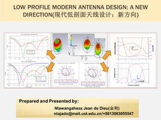
  • 1. LOW PROFILE MODERN ANTENNA DESIGN: A NEW DIRECTION(现代低剖面天线设计:新方向) Prepared and Presented by: Ntawangaheza Jean de Dieu(金利) ntajado@mail.ust.edu.cn/+8613083055547
  • 2. OUTLINE(目录) MPA &AMC historical background conventional MPAs limitations&AMC general applicationsin antenna engineering. AMC integrated MPA design procedures& their numerous applications in modern antenna design. This mayopen up your mind(summing up: where antenna engineering is heading to?)
  • 3. AMC/EBG/RIS/EBG/PBG/DGS/HIS HISTORICAL BACKGROUND(电磁 带隙结构历史背景) 1954 corrugated surfaces(BG) 1959 reactive surfaces 1983 reactive surface using an artificial dielectric 1993 planar&thin 2D AMC/HIS & Idea for reconfigurable HIS 1999 planar&thin with AMC&EBG performance. 1956 Fabry Perot cavity resonant antenna 2005 EBG in the MPA’s GND(DGS) 1986 Fabry Perot resonant cavity antenna improved AMC/EBG/PBG/RIS/HIS Fabry Perot resonant cavity Timeline illustrating historical background of the antenna discussed herein.
  • 4. MPA HISTORICAL BACKGROUND (贴片天线历史背景) Disadvantages • VSWR BW<5% • Gain~6dBi • Large size at low freq. Microstrip patch antenna and printed antenna evolution
  • 5. TRADITIONAL MPA DISADVANTAGES(传统贴片天线的缺点) • Unidirectional pattern with large HPBW(E&H),RCS, and high Xpol(H plane). • Complex feed network with high losses in a large array(phased) leading to a low antenna efficiency and scan blindness. • Electronic beam tilting requires active element which introduces linearity and power handling problems. • Large size at low frequency range as well as narrow bandwidth. (a)Traditional 3 Elts BS antenna with air interference,(b). Unidirectional beam tilt base station,(c) cross polarization A B C
  • 6. AMC/EBG APPLICATIONS IN PRINTEDANTENNAS (电磁带隙结构在印 制天线中的应用) Most of the Applications of AMC in antenna engineering
  • 7. UNIDIRECTIONAL BORESIGHT HIGH GAIN AND WIDEBAND AMC INTEGRATED MPA(基于EBG微带宽频带/高增益天线). Generalized workflow(基本设计流程): Unit cell design Reflection phase diagram Dispersiondiagram Bandgap Antenna& finite AMC structureSim. Theory and simulation tools are used. Band gap or in phase reflectionBW of the finite EBG structure must be wider than the operating BW of the antenna. For stacked antenna&EBG, superstrate must be taken into considerationwhen simulating EBG unit cell.. Classifications (应用类别) EBGsurrounding(C) antenna EBGasantenna’s GND(B) EBGas superstrate(A) (A)Known as resonatorcavity antenna(RCA) or Fabry perot antenna( to improve far field property) (B) Used to enhance both near and farfield( wide band dipole and patch antenna±90°) (C) For patch antennas( only farfields are improved (it takes advantage of band gap)
  • 8. MPA MINIATURIZATION TECHNIQUES(微带天线的小型化常见方法) Shorting pin,dielectric/magnetic loading, meandering/cutting slots, fractals. Low efficiency High Xpol level Narrow VSWR<2 BW Easy of integrationwith MMIC And OEIC. Easy of modelling Narrow VSWR<2 BW SW excitation High 𝜺 𝒓substrateallows more ant.Elts to be assembledtogether to form an array. SW excitation will increase mutual couplingbetween ant.Elts. Leadingto array scanblindnessand low efficiency. EBG row s are placed betweenantenna elts especially in the E plane configuration to drain out SWs. Traditionally and modern antenna miniaturization techniques including their advantages and disadvantages.
  • 9. HIGH 𝜺 VS LOW 𝜺& EBG SURROUNDINGANTENNA ETL(印制在高介 电常数与低介电常数基板微带天线性能特性的比较). Firmly established: E.g.: VSWR<2 BW increasesfrom 2.1 to 4.1% BW for RT5880 and from 1 to 2.1% for RT6010 when antenna sub h is doubled. With RT6010 sub antennasize is halved. Thick and high 𝜺 𝒓 sub yields poor FBR, high SLL and low efficiency due to wave excitation. MPABW increases with increasingsub H and lowing its 𝜀. MPAdirectivity decreases with increasingH
  • 10. IMPROVING MPA ON HIGH 𝜺 SUB RADIATION PATTERN(改善印制在高 介电常数基板上微带天线的辐射特性) Air cavity drill beneath the patch. Use of superstrate and micromachining. Antenna size optimization to deal with. TM0 SW. Complicated designthan original. Large size narrow bandwidth in mostcases AMC/EBG structures, they are compatible with MIMIC/RF circuits. Ease of conformabilityto planar and non planar surfaces Provide smoothand symmetric patterns. OfferreducedSSL,X-pol level and increased FBR. EBG Unit cell and finite EBG structure is characterized and the band gap measured using suspended TXl. Antenna res. freq may shift slightly due to the EBG antenna coupling, and both gain and BW enhancement depends on EBG unit cell number. Ant. 3dB beam width, SSL,FBR and directivity are improved(see red versus green polar plot) Better to study the impact of EBG row No on BW & gain. Use (𝑺 ≥ 𝝀 𝒆𝒇𝒇/𝟐 or 𝑺 ≥ 𝟑𝒑𝒆𝒓𝒊𝒐𝒅𝒊𝒄𝒊𝒕𝒚 as ant.-EBG interspacing as a starting point. Generally, the higher the No, the higher and narrow gain and BW.
  • 11. ENHANCING MPA VSWR/ARBW USINGAMC GND (利用EBG/AMC结 构来改善微带天线驻波比/轴比带宽) EBG row number surrounds an ant. Elt and prohibits SWs propagation, diffractionand reflection. A HIS is designedso that both in phase and surface wave band gap cover antenna operating BW. Only farfield ant. propertiesare improved. Both antenna farfield and nearfield properties are improved with AMC GND. Depending on ant. structure and feeding mechanism,only in phase BW may be needed. Gain(eff.)and BWs(VSWR&AR)are improved due to increase in ant effective aperture( constructive interference)and EBG/ant coupling,respectively. AR BW can be enhanced further using double feed or a superstrate VSWR<2 BW increases from 5% to 35%, with the same antenna volume 0.38x0.27x0.05𝜆 including GND. While an AR<3dB of up 26% is achieved with single feed MPA. Antenna gain is enhanced from 4.56 to 4.74dBi, also FBR is improved due to SWs suppression( red vs blue) a remarkable 3dB beam width is apparent. Insight into how AMC/HIS and antenna achieved VSWR<2/AR<3dB BWs is shown above using equivalent circuit model. AMC C and L as well as patch antenna C,L and R can be calculated using available formulas. For a CP MPA VSWR<2 of 70% is achieved, however gain and AR are limited by unit cell±90°𝐵𝑊
  • 12. Monopole/dipole over AMC GND Vs patch(AMC/EBG结构作为GND的 单极/偶极天线与微带天线辐射特性比较) As for a patch antenna, by using an AMC structure both antenna and image current are in phase resulting in increased gain, BW and eff. It has beenused to reduce the height of wideband/dual band dipole base station antenna acting simultaneously as AMC or PEC GND for the separated bands.
  • 13. Monopole/dipole over AMC GND Vs patch(以AMC/EBG结构作为GND的 单极/偶极天线与微带天线比较) All antennas are mounted on a total height of 0.068𝜆0 and 0.022 𝜆0 over an AMC GND. Patch antenna BW increases from 9.8% to 31.3% with PEC and AMC GND, respectively. Dipole and patch antenna, yield similar pattern and BW, 28.3% and 31.3%, collectively. Their gains are almost the same, they increase with increasing frequencywithin the operating passband. Surface wave antenna can be optimized to yield up to 20% VSWR<2 BW with stable monopole like pattern. The starting antenna(Ref) exhibits 9% whereas the optimized yields 21%. Wide enough for mostWLAN and mobile applications(h~ 0.07𝜆0). Dipole Vs patch over an AMC ground Surface wave patch antenna
  • 14. Filter antennas(滤波天线) Filtering categories Traditional(T) Modern(M) Antennaandfilteraredesigned independentlythereaftercascaded. Thoughsimplebuttheyincrease systemsize,loss,costandweight Co-designapproach,ant.Andfilter aredesignedasoneelement. Lesscost,lowcostandlossalong withreducedsystemweight. Filtering mechanism Actual compactfilter circuit can be integrated with the antenna feeding structure such as filtering power divider, filterbalun... A couple of slots and shorting pins can be used to form indirectly an LC filter. Other resonatorcircuitry Including EBG unit cells and U/…slots are also widely used. Also a couple of stubs and shorting pins can be used to yield the same purpose. Moreover, parasitic resonators can be used not only to increase ant. Gain and BW,but also to enhance the ant. Selectivity( can be a stacked patch, metasurface or DRA) Different terminologies/filtering circuitry locations Frequencynotch antenna: A particular frequencyband is notched within the passband of the antenna( wideband and UWB) Filtering antenna: both gain and return loss performancesshow filtering capability( flat gain curve, sharp band edge and high stopband suppression) Filtering circuitry can be placed within the radiating element,feed or coupled near the antenna or its feed as well the antenna GND. Common filtering antennas Slot resonator fed by multimode resonator ( low gain and wideband) Slotted parasitic patch with filters and vias.
  • 15. Filter antennasdesign examples(滤波天线设计范列) Design procedures Designan antenna which satisfies the required specifications: • VSWR<2BW or filtering requirementnotably flat gain freq. response,sharp band edge(zeros)and high stopband suppression. • Designan unit cell with an in phase characteristic corresponding to the targeted frequencyband. • Make a finite AMC structure and couple it to the filtering antenna to increase gain, BW along with selectivity and skirt. • Or you can notch the fr of interest by coupling one or two unit cell (slots)to the feed mechanism of the wide BW antenna. • Re-optimize your antenna system. Design examples  UWB notch antenna: 3.1-10.6GHzwith band notches at 4-4.5GHz( TV C band 3.7-4.2),5.3-5.9GHz(WLAN)and 7-8GHz(satellite TV).  Filtering antenna: passband in 4-6GHz( C TV, WLAN,WiMAX and C2C) average out of band suppressionof 25dB in upperand lower edge of the antenna passband. Results UWB notched bands Return loss and gain Filtering antenna
  • 16. Traditional high gain antenna design and their limitations (传统高增益天设计以及其弱点) Traditionally high gain performanceis achieved:  Using dish antenna or Yagi Uda antenna.  Linear antenna array and 2D antenna array.  Complexityand size of the array increases with increasing antenna gain. 2D MPAarrays?  They were used to reduce array size while adding more capability to it ( phased array).  Mutual coupling(MC) due to free radiation, SW, fringing field and feed network, deteriorate array performance(effand scan blindness)and increase designcomplexity.  MC depends heavily on elt spacing(s<0.5 𝜆 ), sub property(h& 𝜺) and array size. MC is strongerin E config. than H config.  Gain increases as elt spacing increases,however SSL and number also increases.Thus a (0.5 𝝀<s< 𝝀 ) is usually used. Illustration of antenna array size and gain dependence as well mutual coupling in 2D printed antenna arrays( formulas are embedded) Alternative solutions  Size and costcan be reduced using the so called Fabry Perot resonator cavity antenna(FPRCA)( initiated in1956,1985).  Since the array is no longer in free space,the S can be slightly increased with low SSL, higher gain and low X-pol.  A finite number of EBG row can be placed betweenant. Array elt, especiallyin the E config to reduce SW.propag.
  • 17. 2D array with reduced MC and FPRCA design(低剖面谐振腔 天线设计与降低2D微带天线阵列耦合) MC can be reduced using: • Cavity backed MPAs, substrate removal and multilayer.. • A finite numbers of 2D or 1D EBG are etched in ant. GND or placed betweenant. Array elts. • The EBG BW should be wider than the ant. BW, MC decreases with increasing EBG row No. MC elimination/suppression using an AMC structures RT6010 Fabry Perot resonator cavity antenna • Initiated in 1956 and also known as EBG resonator ant(ERAs), 2D leaky ant and partial reflecting surface ant(PRS). • Planar low profile with a low cost,simple structure while exhibiting low FBR/SSL and X_pol • Increased profile(0.5𝜆 − 0.25𝜆)and narrow 3dB BW due to no uniform aperture phase and amplitude distribution. • Wider3dB BW up to 56%, high peak gain and high eff.are exhibited by feeding a wide VSWR BW ant. with a phase correcting surface(PCS)(printed or multilayered). • An even higher gain is achieved using a multisource to excite the cavity(spacing(s> 𝜆 ) • 3dB BW, peak gain, eff and VSWR dependsupon on Hc( height cavity) h~ 𝝀 𝟎 𝟐 optimum, 𝒉 ≪ 𝝀 𝟎 𝟒 degraded VSWR and 𝝀 𝟎 𝟐𝒉 < 𝟐𝝀 𝟎 high peak gain but narrow 3dB BW. Fabry Perot resonator antenna with PCS to correct no uniform phase and amplitude distribution.
  • 18. FPRCA design(低剖面谐振腔天线设计范烈) Performance prediction & design procedure: Cavity resonant frequencyand phase are given by: 𝒇 = 𝒄 𝟒𝝅𝒉 (𝝋 𝑷𝑹𝑺 + 𝝋 𝑮𝑵𝑫 − 𝟐𝑵𝝅) N=0, 1,2,… For fundamental mode N=0, plus for a PEC GND 𝜑 𝐺𝑁𝐷=𝜋 and thus 𝝋 𝒑𝒓𝒔= 𝟒𝝅𝒉𝒇 𝒄 + 𝟐𝑵(𝟎) − 𝟏 𝝅[𝟏], Antenna gain, 3dB BW &aperture size: 𝑫 𝒑𝒓𝒔 = 𝟏𝟎 × 𝒍𝒐𝒈 𝟏+𝝆 𝟏−𝝆 and 𝑫 𝒕𝒐𝒕𝒂𝒍 = 𝑫 𝒑𝒓𝒔 + 𝑫 𝒇𝒆𝒆𝒅 whereas the aperturesize can be determined using 𝑨 𝒑𝒓𝒔 = 𝟏𝟎 𝟎.𝟏𝑫 𝒕𝒐𝒕𝒂𝒍 × 𝝀 𝟐 𝟎. 𝟖 × 𝝅 𝟐 For our antenna ,the simulated gain is 8.34 at 5GHz, the cavity’s reflectance is 0.72 , giving total directivity and aperture of 16.22dBi and 5.72 𝝀 𝟐 , which can be optimized to 2.65 𝝀 𝟐 . Antenna performance depend heavily on the cavity reflectivity, transmissivity( must>0.6) and an ascendant phase in the fr band of interest. For the EBG GND the Hc can be reduced to 0.25𝜆 Feed antenna sim &unit cell characterization. Antenna and cavity integrated results It is interesting to notice that the antenna achieves high gain(15.8dBi at 5.5GHz),3dB BW(18%) in the predicted band range(5-6GHz). Thus unit cell reflectivity, transmissivity and ascendant phase is an accurate way to predicted the FPRCA performance. The antenna system BW is limited by 3dB BW and that of the VSWR<2 BW.
  • 19. EBG(DGS) to enhance MPA polarization purityand to introduce pattern beam tilting(电磁带隙结构在低交叉极化与倾斜波束中的应 用) Causes of high x_pol level: • Feeding coax radiation and excitation of orthogonal high order mode high x_pol level reduction techniques: • Differential feeding and EBG in antenna’s GND • The formerincrease designcomplexity,size and costwhile the latter improve the Xpol level with no additional circuitry( it increases FBR) • Polarization purity is used in dual polarized and circular polarized(CP) antenna designs. • Beam tilt can be electronic(reduced gain, increased complexityand cost)or mechanical(complexconfiguration). Beam tilt is used to increase signal reception(E tilt) or to avoid co-channel interf.(H tilt) X_pol reductionand beam tilt principle: • According to the resonant cavity modelMPA is surround by six walls with 2E(bottom up) and 4H walls(sides), any modificationmade to 2E walls will changes the antenna current distribution. • For printed dipole antenna near the EBG/AMC GND, the antenna is the near field region, thus modifying the EBG structure will modifyits current and therefore modifying that of the antenna. • Resonant DGS and non resonant DGS structures are widely used to reduce the X pol. X_polreductionand beam tilt principle designexample. • Non resonant DGS has beenused to reduce patch X pol at 2.45GHz(13dB improvement in ± 𝟓𝟎°. ), while the previously designed patchEBG GND has slightly beenmodified to tilt its beam off boresight. Beam tilt EBG dipole antenna X pol reduction using EBG in the GND Patch antenna and low prof dipole
  • 20. Reconfigurable MPAs(可重构微带天线) Example of mechanically reconfig.antenna: Antenna designed to reverselyand intentionally change its farfield(pattern/polarization)or near field(frequency)performances. Goal: Implementationand mechanisms: Overall system size miniaturization and performanceenhancement. Antenna and switch modelling : • Designcomplexityand overall system efficiency. • Practicality of the proposed designparadigm. • Mechanical way( easy to modelbut costly to implement) • Electronic way( difficulty to modelbut easy to implement) • Tunable material(𝝁 𝒓,𝜺 𝒓) and conductivity. Practical considerations: A motorcan be used to rotate a disc over which antenna elements or polarization dependentEBG or stepped unit cells EBG is printed on, depending on the rotation angle pattern, frequencyor polarization reconfigurabilityoperation can be achieved. • Similarly a motor can be used to change the height of the suspendedparasitic element,which changes gain and BW. Example of electronically reconfigurable antenna: Make use of electronically stimulated devices such as PIN diode,RF MEMS, varactor diode inside slotted/fractalantennas to change current path length. Thus switchable(LH/RHCP or linear) and frequencyreconfig is achieved. How to choose a switch? The choice depends on: switch tuning speed, linearity and isolation, power consumption and handling capability and insertion loss. What is a reconfig.Antenna?: • Difficulty depends on the type of switch: PIN diode easy to model than MEMS(2 PINs against 3PINs) • Equivalent circuit model should be used to model the switch behavior. Differentswitch models differentresults The PIN diode on off, can be modelled using a metal pad( loss tangent values), or RLC equivalent circuit for each states. A better way but complex is to take into account 3D package effect of the diode and biasing network. Monopole Antenna for switchable dual and single band operation
  • 21. Open your mind: summing up(总结) Though differentuses of the AMC have been described separately, more than two techniques are usuallyemployed in one antenna system design: (1) A low profile unidirectional wide band or dual wide band (VSWR or AR) patch or dipole can simply be designed by mounting a single feed element(Elt) over an AMC ground. (2) If the wideband performance causes interference with other system, an unit cell can be designed to notch out that frequency which causes the interference. (3) Depending on X-pol design requirement, a DGS can be etched in the PEC of the EBG ground to deal with orthogonal high order modes. Furthermore, if the designed antenna element is used for antenna array , it will exhibit less mutual coupling. (a) A slot antenna excited with multiple resonator structure( stubs slots) is yet another wideband candidate. Furthermore, by introducing a couple of shorting pins antenna’s filtering features can easily be introduced. By stacking an AMC structure above antenna it is expected that the antenna gain, BW and roll of rate will improve drastically. (b) Or the above wideband slot antenna can be covered by a PRS with phase correcting surface to yield relatively high gain and less gain variation within the antenna passband. Finally, stepped unit cells may be utilized to introduce phase delay and therefore achieving beam tilting. Reconfigurability can also be introduced electronically or mechanically.