Download to read offline
![IEEE ANTENNAS AND WIRELESS PROPAGATION LETTERS, VOL. 11, 2012 77
Design and Implementation of an Integrated
UWB/Reconfigurable-Slot Antenna
for Cognitive Radio Applications
Elham Erfani, Javad Nourinia, Member, IEEE, Changiz Ghobadi, Mahmoud Niroo-Jazi, Student Member, IEEE,
and Tayeb A. Denidni, Senior Member, IEEE
Abstract—A new incorporated planar ultrawideband (UWB)/re-
configurable-slot antenna is proposed for cognitive radio applica-
tions. A slot resonator is precisely embedded in the disc monopole
radiator to achieve an individual narrowband antenna. A varactor
diode is also deliberately inserted across the slot, providing a re-
configurable frequency function in the range of 5–6 GHz. The slot
is fed by an off-centered microstrip line that creates the desired
matching across the tunable frequency band. The measured an-
tenna parameters are presented and discussed, confirming the sim-
ulation results.
Index Terms—Cognitive radio (CR), frequency-reconfigurable,
slot antenna, ultrawideband (UWB) antenna, varactor diode.
I. INTRODUCTION
CURRENT communication networks operate by Fixed
Spectrum Access (FSA) policy, in which some parts
of the available spectrum have been assigned to one or more
users, and other users do not have the permission to use the
dedicated band. With developing wireless communications and
increasing demands for operating frequency bands, the radio
spectrum has become scarce and congested. However, licensed
users act sporadically within their assigned band such that,
most of the time, operating frequency region can be idle. To
efficiently use the available spectrum band and hence address
the spectrum congestion, cognitive radio networks (CRNs)
based on Dynamic Spectrum Access (DSA) and spectrum
management technique have been proposed [1].
CRNs have two types of users: 1) primary users with licenses
to act in certain spectrum bands; 2) CR users (secondary users)
that have no allocated bands. CR users are considered as vis-
itors to use idle frequency region portions of primary users in
real time [2]. Hence, they should have comprehensive aware-
ness from licensed and unlicensed bands in its operating en-
vironment. Through sensing and measurement of interference
temperature and level of signal energy [2], CR can detect hole
Manuscript received September 28, 2011; revised November 24, 2011; ac-
cepted December 30, 2011. Date of publication January 04, 2012; date of cur-
rent version March 19, 2012.
E. Erfani, J. Nourinia, and C. Ghobadi are with the Department of Elec-
trical Engineering, Urmia University, Urmia, Iran (e-mail: el.erfani@yahoo.
com; j.nourinia@urmia.ac.ir; ch.ghobadi@urmia.ac.ir).
M. Niroo-Jazi and T. A. Denidni are with INRS, Université de Québec, Mon-
treal, QC H5A 1K6, Canada (e-mail: njazi@emt.inrs.ca; denidni@emt.inrs.ca).
Color versions of one or more of the figures in this letter are available online
at http://ieeexplore.ieee.org.
Digital Object Identifier 10.1109/LAWP.2011.2182631
spectrums (white spectrums) in any time and select the best band
region according to the quality-of-service (QoS) requirements.
As soon as this portion of spectrum is requested to use by the pri-
mary user, the CR user should vacant this frequency band and
reconfigure its transmission parameters to achieve a new suit-
able hole spectrum.
In the aspect of hardware, CR needs a specialized antenna
for monitoring and communicating. In the recent years, dif-
ferent antenna designs for CR application have been reported
in [3]–[7]. An ultrawideband (UWB) and a reconfigurable nar-
rowband antenna can be chosen to handle sensing and com-
munication functions, respectively. A technique based on in-
tegrating these two antennas into a same substrate has been
proposed in [3] and [4]. In [3], as a narrowband antenna, a
planar inverted-F resonator is printed on the reverse side of a
coplanar waveguide (CPW)-fed UWB monopole antenna, and
it utilizes the radiator of UWB as its own ground plane. In this
structure, a matching circuit has been used to tune this antenna
for three operating regions centered around 4, 8, and 10 GHz,
leading to increase the antenna complexity and size. In [4], a
UWB egg-shaped monopole antenna and five different narrow-
band patch radiators inside a circular section are printed on a
same substrate. The operating frequency of this antenna can be
adjusted by physically rotating the circular part via a stepper
motor. At each rotation step, a certain frequency band is ob-
tained by feeding an individual patch radiator. However, using a
stepper motor requires more space and increases the complexity
and cost of the antenna.
In another technique, sensing and communicating antennas
are realized by switching between a narrowband antenna and a
UWB resonator [5]–[7]. The antenna structure is fed by a single
terminal in this case. This method is achieved by two ways:
1) incorporating a bandpass filter inside a UWB antenna [5], [6];
2) changing the structure of the antenna radiator or ground plane
via switches [7]. A reconfigurable bandpass filter is integrated
with a UWB antenna in [5]. The reconfigurability is based on in-
corporating nine switches within the defected microstrip struc-
ture (DMS) bandpass filter.
Today, in mobile systems, a compact antenna with high per-
formance features, low cost, and less complexity is demanded.
In this letter, a new antenna configuration for CRNs is presented.
This antenna is constructed by incorporating a reconfigurable
slot resonator into an UWB antenna in a unique substrate, while
the antenna size is kept small. Simulated and experimental re-
sults of the fabricated prototype are presented and compared.
1536-1225/$31.00 © 2012 IEEE
Authorized licensed use limited to: Birla Institute of Technology & Science. Downloaded on April 27,2020 at 13:32:14 UTC from IEEE Xplore. Restrictions apply.](https://image.slidesharecdn.com/06122485-220608130145-03b9321a/85/06122485-pdf-1-320.jpg)
![IEEE ANTENNAS AND WIRELESS PROPAGATION LETTERS, VOL. 11, 2012 77
Design and Implementation of an Integrated
UWB/Reconfigurable-Slot Antenna
for Cognitive Radio Applications
Elham Erfani, Javad Nourinia, Member, IEEE, Changiz Ghobadi, Mahmoud Niroo-Jazi, Student Member, IEEE,
and Tayeb A. Denidni, Senior Member, IEEE
Abstract—A new incorporated planar ultrawideband (UWB)/re-
configurable-slot antenna is proposed for cognitive radio applica-
tions. A slot resonator is precisely embedded in the disc monopole
radiator to achieve an individual narrowband antenna. A varactor
diode is also deliberately inserted across the slot, providing a re-
configurable frequency function in the range of 5–6 GHz. The slot
is fed by an off-centered microstrip line that creates the desired
matching across the tunable frequency band. The measured an-
tenna parameters are presented and discussed, confirming the sim-
ulation results.
Index Terms—Cognitive radio (CR), frequency-reconfigurable,
slot antenna, ultrawideband (UWB) antenna, varactor diode.
I. INTRODUCTION
CURRENT communication networks operate by Fixed
Spectrum Access (FSA) policy, in which some parts
of the available spectrum have been assigned to one or more
users, and other users do not have the permission to use the
dedicated band. With developing wireless communications and
increasing demands for operating frequency bands, the radio
spectrum has become scarce and congested. However, licensed
users act sporadically within their assigned band such that,
most of the time, operating frequency region can be idle. To
efficiently use the available spectrum band and hence address
the spectrum congestion, cognitive radio networks (CRNs)
based on Dynamic Spectrum Access (DSA) and spectrum
management technique have been proposed [1].
CRNs have two types of users: 1) primary users with licenses
to act in certain spectrum bands; 2) CR users (secondary users)
that have no allocated bands. CR users are considered as vis-
itors to use idle frequency region portions of primary users in
real time [2]. Hence, they should have comprehensive aware-
ness from licensed and unlicensed bands in its operating en-
vironment. Through sensing and measurement of interference
temperature and level of signal energy [2], CR can detect hole
Manuscript received September 28, 2011; revised November 24, 2011; ac-
cepted December 30, 2011. Date of publication January 04, 2012; date of cur-
rent version March 19, 2012.
E. Erfani, J. Nourinia, and C. Ghobadi are with the Department of Elec-
trical Engineering, Urmia University, Urmia, Iran (e-mail: el.erfani@yahoo.
com; j.nourinia@urmia.ac.ir; ch.ghobadi@urmia.ac.ir).
M. Niroo-Jazi and T. A. Denidni are with INRS, Université de Québec, Mon-
treal, QC H5A 1K6, Canada (e-mail: njazi@emt.inrs.ca; denidni@emt.inrs.ca).
Color versions of one or more of the figures in this letter are available online
at http://ieeexplore.ieee.org.
Digital Object Identifier 10.1109/LAWP.2011.2182631
spectrums (white spectrums) in any time and select the best band
region according to the quality-of-service (QoS) requirements.
As soon as this portion of spectrum is requested to use by the pri-
mary user, the CR user should vacant this frequency band and
reconfigure its transmission parameters to achieve a new suit-
able hole spectrum.
In the aspect of hardware, CR needs a specialized antenna
for monitoring and communicating. In the recent years, dif-
ferent antenna designs for CR application have been reported
in [3]–[7]. An ultrawideband (UWB) and a reconfigurable nar-
rowband antenna can be chosen to handle sensing and com-
munication functions, respectively. A technique based on in-
tegrating these two antennas into a same substrate has been
proposed in [3] and [4]. In [3], as a narrowband antenna, a
planar inverted-F resonator is printed on the reverse side of a
coplanar waveguide (CPW)-fed UWB monopole antenna, and
it utilizes the radiator of UWB as its own ground plane. In this
structure, a matching circuit has been used to tune this antenna
for three operating regions centered around 4, 8, and 10 GHz,
leading to increase the antenna complexity and size. In [4], a
UWB egg-shaped monopole antenna and five different narrow-
band patch radiators inside a circular section are printed on a
same substrate. The operating frequency of this antenna can be
adjusted by physically rotating the circular part via a stepper
motor. At each rotation step, a certain frequency band is ob-
tained by feeding an individual patch radiator. However, using a
stepper motor requires more space and increases the complexity
and cost of the antenna.
In another technique, sensing and communicating antennas
are realized by switching between a narrowband antenna and a
UWB resonator [5]–[7]. The antenna structure is fed by a single
terminal in this case. This method is achieved by two ways:
1) incorporating a bandpass filter inside a UWB antenna [5], [6];
2) changing the structure of the antenna radiator or ground plane
via switches [7]. A reconfigurable bandpass filter is integrated
with a UWB antenna in [5]. The reconfigurability is based on in-
corporating nine switches within the defected microstrip struc-
ture (DMS) bandpass filter.
Today, in mobile systems, a compact antenna with high per-
formance features, low cost, and less complexity is demanded.
In this letter, a new antenna configuration for CRNs is presented.
This antenna is constructed by incorporating a reconfigurable
slot resonator into an UWB antenna in a unique substrate, while
the antenna size is kept small. Simulated and experimental re-
sults of the fabricated prototype are presented and compared.
1536-1225/$31.00 © 2012 IEEE
Authorized licensed use limited to: Birla Institute of Technology & Science. Downloaded on April 27,2020 at 13:32:14 UTC from IEEE Xplore. Restrictions apply.](https://image.slidesharecdn.com/06122485-220608130145-03b9321a/75/06122485-pdf-1-2048.jpg)
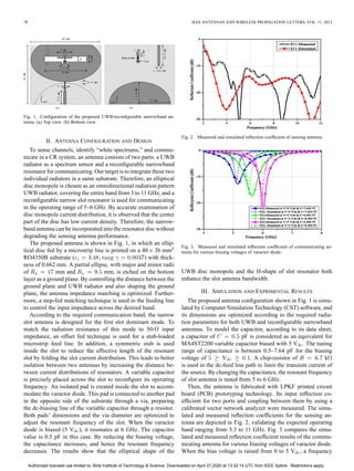
![80 IEEE ANTENNAS AND WIRELESS PROPAGATION LETTERS, VOL. 11, 2012
Fig. 9. Measured and simulated reconfigurable slot antenna radiation pattern
at 5.5 GHz. (a) -plane. (b) -plane.
Fig. 10. Measured and simulated reconfigurable slot antenna radiation pattern
at 6 GHz. (a) -plane. (b) -plane.
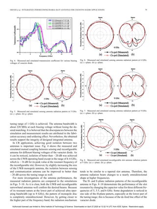
The measured and simulated gains of UWB antenna in the
-plane are shown in Fig. 11. For comparison, the simulated
peak gain of the antenna is depicted in this figure as well. The
antenna gain in the -plane is measured using comparison
method, confirming the predicted result. Since different parts
of the UWB antenna are radiated across the bandwidth, its ra-
diation pattern is changing, and therefore some gain reduction
is observed in the ranges of 5–6 and 9–12 GHz.
However, as it can be noticed in this figure, the calculated
peak gain of the antenna demonstrates smother response with
better gain compared to the ones obtained in -plane. The
measured peak gains of the reconfigurable antenna for the fre-
quencies of 5, 5.5, and 6 GHz are 1.87, 1.36, and 1.73 dB,
respectively.
Fig. 11. Measured and simulated peak gain of UWB antenna.
IV. CONCLUSION
In this letter, an integrated elliptical monopole antenna with
reconfigurable slot radiator on a same substrate has been suc-
cessfully introduced for cognitive radio applications. This an-
tenna can offer sensing and communicating functions with a rea-
sonable size. The achieved results have shown that the isolation
between the narrow and UWB antenna is reduced to better than
16 dB by folding the slot resonator current distribution using
a balanced stub inside the slot. Moreover, by an offset-fed con-
figuration, the first dominant mode of the slot can easily be ex-
cited, providing the desired wireless communication operating
frequency bandwidth.
REFERENCES
[1] J. Mitola, III, “Cognitive radio for flexible mobile multimedia commu-
nications,” in Proc. IEEE MoMuC, 1999, pp. 3–10.
[2] I. F. Akyildiz, W. Y. Lee, M. C. Vuran, and S. Mohanty, “A survey on
spectrum management in cognitive radio networks,” IEEE Commun.
Mag., vol. 46, no. 4, pp. 40–48, Apr. 2008.
[3] E. Ebrahimi, J. R. Kelly, and P. Hall, “Integrated wide-narrowband
antenna for multi-standard radio,” IEEE Trans. Antennas Propag., vol.
59, no. 7, pp. 2628–2635, Jul. 2011.
[4] Y. Tawk, J. Costantine, K. Avery, and C. G. Christodoulou, “Imple-
mentation of a cognitive radio front-end using rotatable controlled re-
configurable antennas,” IEEE Trans. Antennas Propag., vol. 59, no. 5,
pp. 1773–1778, May 2011.
[5] M. Zamudio, Y. Tawk, J. Kim, and C. G. Christodoulou, “Integrated
cognitive radio antenna using reconfigurable band pass filters,” in Proc.
5th Eur. Conf. Antennas Propag., 2011, pp. 2108–2112.
[6] M. R. Hamid, P. Gardner, P. S. Hall, and F. Ghanem, “Vivaldi antenna
with integrated switchable band pass resonator,” IEEE Trans. Antennas
Propag., vol. 59, no. 11, pp. 4008–4015, Nov. 2011.
[7] J. R. Kelly, P. S. Hall, and P. Song, “A reconfigurable wideband handset
antenna operating from 460 MHz to 12 GHz,” in Proc. IEEE Antennas
Propag. Soc. Int. Symp., 2009, pp. 1–4.
Authorized licensed use limited to: Birla Institute of Technology & Science. Downloaded on April 27,2020 at 13:32:14 UTC from IEEE Xplore. Restrictions apply.](https://image.slidesharecdn.com/06122485-220608130145-03b9321a/85/06122485-pdf-4-320.jpg)

This document describes the design and implementation of an integrated ultrawideband (UWB)/reconfigurable-slot antenna for cognitive radio applications. A slot resonator is embedded in a disc monopole radiator to achieve a narrowband antenna, and a varactor diode is inserted across the slot to provide frequency reconfiguration between 5-6 GHz. Simulation and measurement results show the antenna achieves UWB performance from 3-11 GHz as well as tunable narrowband operation across the targeted range. Isolation between the UWB and narrowband functions is better than 16 dB across most of the operating bands.


