SlideShare a Scribd company logo
1 of 152
1
TOYOTA Hybrid Technology
2
Contents
What is the Hybrid Vehicle?
THS II (TOYOTA Hybrid System)
Engine
Hybrid Transaxle
Inverter Assembly
HV Battery
THS II Operation
ECB (Electronically Controlled Brake)
Indicator and Warning
Other System
Service Point
Other Hybrid Vehicles
3
What is the Hybrid Vehicle?
4
CO2
Concentration
500
300
260
600
400
(ppmv)
1200 1400 1600 1800 2000
2100
What is the Hybrid Vehicle?
Why is the hybrid vehicle necessary?
Low fuel consumption and low CO2 emission
vehicle is required
Increase Automobile
market
Expanding Energy
Consumption
2006
1970
5
What is the Hybrid Vehicle?
Why is the hybrid vehicle necessary?
– Hybrid technology is the core for eco-car development
•Low fuel consumption
•Low CO2 emission
THS II
FCHV
THS
Ultimate eco-car
CNG DPR
DPNR
Common-rail VVT-i
Lean Burn
D-4
EV
Diesel
Engine
Alternative
Energy
Gasoline
Engine
Electric
Vehicle
6
What is the Hybrid Vehicle?
Kind of Hybrid System
– Series Hybrid System
• In this system, the engine is used to supply
electrical power to the motor, which then turns the
wheels
7
What is the Hybrid Vehicle?
Kind of Hybrid System
– Parallel Hybrid System
• The wheels are driven by both the engine and the
motor
8
What is the Hybrid Vehicle?
Kind of Hybrid System
– THS (TOYOTA Hybrid System)
• Strong points of both series/parallel systems
realized in one system
9
What is the Hybrid Vehicle?
THS II (TOYOTA Hybrid System)
– Concept
Higher
Power
Low Fuel
Consumption
10
What is the Hybrid Vehicle?
THS II (TOYOTA Hybrid System)
– Hybrid vehicle realizes low fuel consumption and
higher power
PRIUS
(NHW20)
Japanese
10
–
15
Mode
Fuel
Efficiency
(km/L)
0 – 100 km/h Acceleration (sec.)
Good Acceleration
Good Fuel
Economy
PRIUS
(NHW11)
Corolla
(1.3L) Corolla
(1.5L)
CAMRY
(2.4L)
Tradeoff between performance
and fuel economy in
conventional vehicle
11
What is the Hybrid Vehicle?
Driving Method
– The vehicle can run on gasoline only, and does not
need to be recharge
– If the battery charge drops, the engine drives the
generator, which recharges the battery
12
What is the Hybrid Vehicle?
Driving Method
– The vehicle may be driven while the “READY” light is
ON
– The engine will stop while the vehicle is stopped, in
order to improve fuel economy
– The engine starts up automatically after the vehicle
starts off
13
THS II
(TOYOTA Hybrid System)
PRIUS [NHW20]
14
THS II (TOYOTA Hybrid System)
Main Component Location
HV Battery
Engine
Inverter
Hybrid Transaxle
•Generator (MG1)
•Motor (MG2)
•Power-dividing Mechanism Click Movie
15
MOVIE
Shift Lever
Parking Switch
Shift Lever
Main Component Location
THS II (TOYOTA Hybrid System)
16
THS II (TOYOTA Hybrid System)
System Diagram
HV
Battery
Brake
Actuator
Auxiliary
Battery
Electric A/C
Compressor
A/C
Inverter
DC – DC
Converter
SMR1, 2 and 3
Boost
Converter
MG1 MG2
Hybrid Transaxle
Inverter
Engine
Shift Position
Sensor
(Shift, Select)
Accelerator
Pedal Position
Sensor
EV Mode
Switch
Speed
Sensors
CAN
Engine
ECU
Skid Control
ECU
Battery
ECU
DLC3
HV
ECU
Click here to see
operation of
shift lever
17
THS II (TOYOTA Hybrid System)
Outline
– Compression from conventional vehicle
Item
Conventional
Vehicle
THS II Note for THS II
Power
Source
Engine
•Engine
•Motor
•Generator
•Motor drive is possible
(Engine OFF)
•Engine motive force is
divided for drive and
electric generation
Trans-
mission
•A/T
•M/T
Power Splitting
Device
•Divide the engine, motor
and generator power
•Function as CVT
Brake Hydraulic Brake
•Hydraulic Brake
•Regenerative Brake
Cooperative control
between hydraulic and
regenerative brake
Battery 12V Battery
•12V Battery
•201.6V Battery
High-voltage supply for
motor drive
Power
Train
Control
Engine ECU
•HV ECU
•Engine ECU
•Inverter
Controls the engine,
motor and generator
18
THS II (TOYOTA Hybrid System)
Outline
– System operation
Start-off
Normal
Driving Acceleration Deceleration Stop
Electric
motor only
Motor and
Engine
Motor and Engine
(additional power
drawn from battery)
Battery
charging
Engine
automatically
shuts off
19
THS II (TOYOTA Hybrid System)
1NZ-FXE Engine
– 1.5 liter, In-line 4-cylinder, 16-valve DOHC, gasoline
engine
1NZ-FXE
X = Atkinson Cycle
20
THS II (TOYOTA Hybrid System)
Hybrid Transaxle
– Includes AC 500V motor, generator and power-
dividing mechanism
– Uses a continuously variable transmission mechanism
to achieve smooth and quiet operations
MG1
MG2
Power-dividing
Mechanism
21
THS II (TOYOTA Hybrid System)
HV Battery
– Full sealed nickel metal hydride (Ni-MH) battery
– DC 201.6V
– Located behind the rear seat
22
THS II (TOYOTA Hybrid System)
Inverter Assembly
– Inverter
• DC  AC high voltage
– Variable-voltage System
• DC 200V stepped up to
Max. DC 500V
– DC-DC Converter
• DC 200V stepped down
to DC 12V
– A/C Inverter
• DC  AC to drive the
A/C compressor
23
THS II (TOYOTA Hybrid System)
Brake System
– ECB (Electrically Controlled Brake)
– Hydraulic brake pressure is controlled by electrical
signal and cooperate regenerative brake
Skid
Control
ECU
Vehicle Condition
Driver’s Demand
HV ECU
Regenerative
Brake Control
Hydraulic
Brake Control
24
THS II (TOYOTA Hybrid System)
Steering System
– EPS (Electric Power Steering) is used
EPS ECU
EPS Motor
25
THS II (TOYOTA Hybrid System)
Air Conditioning System
– Compact, high-performance scroll compressor driven
by motor
Electric Inverter Compressor
26
THS II (TOYOTA Hybrid System)
Multi Display
– Energy Monitor
27
THS II (TOYOTA Hybrid System)
Multi Display
– Fuel consumption indicator
28
THS II (TOYOTA Hybrid System)
Auxiliary Battery (12V)
– Auxiliary battery supplies power to headlights, audio,
and all ECUs
– Sealed-type battery is used
Auxiliary
Battery
29
THS II (TOYOTA Hybrid System)
Power Cable
– Orange-colored wire harness / connector
High-voltage circuit
High-voltage Wire Harness
30
THS II (TOYOTA Hybrid System)
Service Plug
– Shut off the high-voltage circuit
Caution: Wear insulated gloves when disconnecting / connecting the
service plug to prevent against electrical shock
Service Plug
31
Engine
32
Engine
Atkinson Cycle
– The “X” of the 1NZ-FXE indicates the use of the
Atkinson cycle, the principle applied for this vehicle’s
engine
Atkinson cycle
High thermal efficiency
1NZ-FXE (PRIUS)
33
Engine
Overview
– Atkinson cycle
Compression Stroke < Expansion Stroke
High thermal efficiency
Compression Expansion
34
Engine
Overview
– Atkinson cycle
• Depending on the driving condition, the cylinder
volume is varied by VVT-i
Valve Timing (Intake Valve)
TDC
BDC
72º
105º
VVT-i
Operation
Cylinder Volume
105º
72º
90º
38
Engine
Overview
– Specifications
Item 1NZ-FXE (’04 PRIUS) 1NZ-FE (Corolla)
No. of Cylinders & Arrangement 4-Cylinder, in-line 
Valve Mechanism
16-Valve DOHC,
Chain Drive, VVT-I

Displacement cm3 (cu. in.) 1497 (91.3) 
Bore x Stroke mm (in.) 75.0 x 84.7 (2.95 x 3.33) 
Compression Ratio 13.0 10.5
Max. Output EEC (-W, -Q) 57 kW @ 5000 rpm 78 kW @ 6000 rpm
Max. Torque EEC (-W, -Q) 115 N·m@ 4200 rpm 145 N·m@ 4200 rpm
Valve
Timing
Intake
Open 18 - -15 BTDC 42 - -2 BTDC
Close 72 - 105 ABDC 10 - 50 ABDC
Exhaust
Open 34 BBDC 42 BBDC
Close 2 ATDC 
Emission Regulation STEP IV STEP III
39
Engine
Overview
– Engine compartment
Radiators (for engine and
inverter) are one piece
Drive belt simply layout
TOYOTA Genuine
Super LLC
40
Engine
Overview
– Interior
32-bit engine ECU with
CAN communication
Non-contact type accelerator
pedal position sensor
41
Engine
Overview
– Under floor
Plastic Type Fuel
Tank (-W, -Q)
42
Shape is changed
to weight reduction
223g (Corolla)

194g (Prius)
Piston skirt portion is
reduced to friction reduction
New resin coat to
friction reduction
Engine
Engine Proper
– Piston
• Lightweight and low friction
Corolla
Prius
43
Engine
Piston
Ring
Cross section Tension Thickness Others
Top
Ring
Inner Bevel Type
4.2 N

3 N
1.2 mm (0.047 in.)

0.8 mm (0.031 in.)
PVD coat is used to
improve wear
resistance
Second
Ring
Taper Type
3.3 N

3 N
1.2 mm (0.047 in.)

1.0 mm (0.039 in.)
Steel material is
used to improve
wear resistance
Oil Ring
2 Piece Type
17 N

8 N
2.0 mm (0.079 in.)

1.5 mm (0.059 in.)
-
Corolla

Prius
 Engine Proper
• Piston Ring
– Lower tension and thinner piston ring is used for
friction reduction
44
Engine
Throttle Body (ETCS-i)
Throttle valve is controlled by the HV ECU.
ETCS-i also controls the cruise control system.
45
Engine
Radiator
(for engine)
Radiator
(for Inverter)
Front
Drain Plug
(for engine)
 Cooling System
Radiators (for engine and inverter) are one piece
46
Engine
Coolant Heat Storage System
– General
• This system reduces the amount of adhesion of fuel
on the intake port wall after engine starting
Hot coolant in
the tank
Before engine start
Hot coolant to
cylinder head Heated
Amount of
adhesion of
fuel is
reduced after
engine start
47
Engine
Coolant Heat Storage System
– Components
Coolant Heat Storage
Tank Outlet Temp. Sensor
Engine Coolant
Temp. Sensor
Coolant Heat
Storage
Water Pump
Water
Valve
Water Pump
(for Heater)
Coolant Heat
Storage Tank
to / from
heater core
Reverse Side
48
Engine
Coolant Heat Storage System
– Operation
• Engine running (w/o storage operation)
Cylinder
Block
Water
Pump
Water
Pump
Heater
Core
Cylinder Head
OF
F
Water
Valve
49
Engine
Coolant Heat Storage System
– Operation
• Storage operation (during engine running)
Cylinder
Block
Water
Pump
Water
Pump
Heater
Core
Cylinder Head
OF
F
Hot coolant
is stored
Water
Valve
50
Engine
Coolant Heat Storage System
– Operation
• Storage operation (during engine running)
 Operation chart
Warm-up
Others
Storage operation (during engine running)
[Max.: 4 times]
Meets start
conditions
Meets stop
conditions
Engine
Starting
Tank coolant temp. is
90 °C (194 °F) or
more
Storage is
Completed
Confidential
51
Engine
Coolant Heat Storage System
– Diagnosis
• DTCs for Coolant Heat Storage System
DTC
No.
Detection Item
DTC
No.
Detection Item
P1115
Coolant temp. sensor circuit for
coolant heat storage system
P1122
Water valve position sensor circuit
low
P1116
Coolant temp. sensor circuit stuck
for coolant heat storage system
P1123
Water valve position sensor circuit
high
P1117
Coolant temp. sensor circuit low for
coolant heat storage system
P1150
Coolant Path Clog Up for Coolant
Heat Storage System
P1118
Coolant temp. sensor circuit high
for coolant heat storage system
P1151 Coolant Heat Storage Tank
P1120 Water valve position sensor circuit P2601
Coolant pump control circuit range /
performance
P1121
Water valve position sensor circuit
stuck
P2610
ECM / PCM internal engine off timer
performance
52
Engine
Coolant Heat Storage System
– Service Point
• Coolant Replacement
 Drain engine coolant
1. Disconnect the coolant heat storage water pump connector
2. Remove the radiator cap
3. Connect a vinyl hose to drain cocks (engine, radiator, coolant
heat storage tank)
4. Loosen the drain cock plugs (engine, radiator, coolant heat
storage tank), and drain coolant
5. Drain the coolant in the radiator reservoir tank
Caution: The coolant in coolant heat storage tank is
hot even if engine and radiator are cold
53
Engine
Coolant Heat Storage System
– Service Point
• Coolant Replacement
 Fill engine coolant
1. Tighten the drain cock plugs and disconnect a vinyl hose (engine,
radiator, coolant heat storage tank)
2. Connect a vinyl hose to the bleeder plug of radiator and insert the
another side of hose to reservoir tank
3. Using 6 mm socket hexagon wrench, loosen the radiator bleeder plug
from service hole
4. Fill the coolant into the radiator
5. Tighten the radiator bleeder plug and install the radiator cap
6. Fill the radiator reservoir tank with coolant to the full level
7. Connect the coolant heat storage water pump connector
8. Connect the Intelligent Tester II to DLC3 and turn to IG/ON
54
Engine
Coolant Heat Storage System
– Service Point
• Coolant Replacement
 Fill engine coolant
9. Perform the ACTIVE TEST of water pump (coolant heat storage water
pump operates for 30 sec.)
10. Loosen the radiator bleeder plug and fill the coolant into the radiator
11. Tighten the radiator bleeder plug
12. Repeat the steps 9 to 11 until coolant cannot be added
13. Disconnect the vinyl hose
14. Warm-up engine until the thermostat is opened (inspection mode)
15. Stop the engine, and wait until the coolant gets cold
16. Fill the coolant into the radiator
17. Repeat the step 14 to 16 until coolant level stops going down
18. Check DTC and clear the DTC which relates to the water pump
55
Engine
Fuel System
(Vapor reducing fuel tank)
Reduce the amount of
fuel vapors released
when vehicle is
parked.
56
Engine
Fuel System
(Vapor reducing fuel tank)
It is composed of two parts:
a metal outer tank,
and a plastic
membrane inside the
fuel tank.
NOTE:
Normal tank capacity
is 45 liters; tank
capacity decreases by
5 liters at –10°C.
Click!
zoom
58
Engine
Fuel System
(Vapor reducing fuel tank)
Fuel Sender Gauge
Sub-tank is installed
inside the fuel tank,
inside which a fuel
pump and sender
gauge are attached.
Sub-tank
Fuel Sender Gauge
59
Engine
Fuel System
(Vapor reducing fuel tank)
Fuel Sender Gauge
The fuel pump and
sender gauge can not
be removed from the
fuel tank.
If the pump or gauge
malfunctions
Replace the tank
assembly
60
Engine
Drive Belt System
– A/C compressor pulley is not existing
– Simply belt layout
A/C compressor
pulley is not existing
Water Pump Pulley
Crank Pulley
Idler Pulley
Adjust Bolt
61
Hybrid Transaxle
62
Hybrid Transaxle
Overview
– P112 type
– Components:
• MG (Motor Generator) 1
• MG (Motor Generator) 2
• Power-dividing Mechanism (Planetary Gears)
• Reduction Mechanism
• Differential Mechanism
– Fluid type: ATF WS
– Capacity: 3.8 liters
63
Hybrid Transaxle
Overview
– P112 type
MG2 MG1
Planetary Gears
Chain-drive
Sprocket
64
Hybrid Transaxle
Overview
– P112 type
Counter
Drive Gear
Final Drive
Pinion Gear
Counter-
driven Gear
Final Ring
Gear
Chain-driven
Sprocket
Reduction
Mechanism
Differential
Mechanism
65
Hybrid Transaxle
MG1 / MG2
– Compact and lightweight, highly efficient AC500V
motor generator
MG2
MG1
66
Hybrid Transaxle
MG1
– Main operations  Generator
– When engine starting  Starter
MG1
Stator Coil
Rotor
Speed Sensor
67
Hybrid Transaxle
MG2
– When driving  Main power to engine power (Starting
off) or provides supplementary
– When braking  Converts kinetic energy to
electrical energy
MG2
Stator Coil Rotor
Speed Sensor
68
Hybrid Transaxle
Speed Sensor (Resolver)
– Detects position, speed and direction of MG1 / MG2
rotors
Speed Sensor
(for MG1)
Speed Sensor
(for MG2)
69
Hybrid Transaxle
Transaxle Damper
– Installed at location of conventional clutch
Reduces shock which occurs when kinetic energy is
transmitted
70
Hybrid Transaxle
Cooling System
– Cooling circuit is used for both MG1 / MG2
– Separate cooling system from engine
Reservoir
Pump
MG1 / 2
Radiator
Inverter
Reservoir Tank
Radiator
Electric
Water Pump
71
Hybrid Transaxle
Oil Pump
– Forced lubrication system via trochoid pump used to
lubricate main shaft bearings
– Oil pump functions when engine is being driven
Oil Pump
72
Hybrid Transaxle
Mayor Different with Prius Generation III
73
Inverter Assembly
74
Inverter Assembly
Components
– Inverter
• DC  AC high voltage
– Variable-voltage System
• DC201.6V stepped up to
max. DC500V
– DC-DC Converter
• DC201.6V stepped down
to DC 12V
– A/C Inverter
• DC  AC to drives the
A/C compressor
75
Inverter Assembly
Components
HV Battery
Inverter Assembly
A/C
Inverter
Variable-
voltage
System
MG1
MG2
Inverter
DC - DC
Converter
76
Inverter Assembly
Variable-voltage System
– DC 201.6V  Max. DC 500V conversion
HV Battery
DC 201.6V DC500V
Variable-
voltage System
•IPM (IGBT)
•Reactor
Max. DC 500V
 
DC 201.6V
Inverter Assembly
AC500V
MG2
: Discharge : Charge
MG1
Inverter
(IPM)
77
Inverter Assembly
Inverter Operation
– Motor control
Motor Torque is controlled
by the current value
Motor Speed is controlled by
the frequency
Low
Torque
High
Torque
Low
Speed
High
Speed
78
Inverter Assembly
DC – DC Converter
– DC201V  DC 12V
DC 201.6V
DC – DC Converter
Inverter Assembly
Auxiliary
Battery
DC 12V
DC

AC
AC 201.6V

AC 12V
AC

DC
MG1
MG2
HV Battery
Inverter
Variable-
voltage
System
79
Inverter Assembly
A/C inverter
– DC201.6V  AC201.6V conversion
Electric
Inverter
Compressor
HV ECU
HV Battery
A/C ECU
Target
Compressor
Speed
DC 201.6V
AC 201.6V
A/C Inverter
DC 201.6V

AC 201.6V
Inverter Assembly
80
Inverter Assembly
Cooling System
– Cooling circuit is used for inverter assembly
– Separate cooling system from engine
Reservoir
Pump
MG1 / 2
Radiator
Inverter
Reservoir Tank
Radiator
Electric
Water Pump
81
HV Battery Assembly
82
HV Battery Assembly
Power Supply
– The HV battery supplies power to MG1 / MG2
– The auxiliary battery supplies power to HV ECU and
Engine ECU (all ECU)
– When both are functioning properly, the vehicle will
start
HV Battery
(DC 201.6V)
Auxiliary Battery
(DC 12V)
83
HV Battery Assembly
Components
Current
Sensor
SMR3
SMR2
Resister
Module
Battery ECU
SMR1
Service
Plug
Connector
84
HV Battery Assembly
Battery Module
– Nickel metal hydride (Ni-MH) battery
(1.2V x 6 cells) x 28 modules = 168 cells = DC 201.6 V
28 Module
Module
(1.2V x 6 cells)
85
HV Battery Assembly
Battery ECU
– Maintains control of HV battery SOC (State of charge)
– Ensures battery capability
Service
Plug
Temp. Sensors
(Thermistor)
Battery
Cooling Fan
Motor
HV Battery
Current
Sensor
Voltage x 14
+
-
Temp. x 4
Battery ECU
SOC
Control
Cooling Fan
Control
Electrical Leakage Detection
for High-voltage System
Diagnosis Function
for HV Battery
HV Battery
Condition Detection
•HV ECU
•Engine ECU
•A/C ECU
CAN
Battery
Cooling Fan
Relay
Battery
Cooling Fan
Controller
86
HV Battery Assembly
Battery ECU
– Controls SOC to match THS characteristics
– The SOC is maintained at approx, 60%. A margin is
given for further recharging via regenerative braking
– Sends requests to HV ECU to obtain desired SOC
87
HV Battery Assembly
SOC Control
– When the SOC is dropped, battery ECU sends the
“Charge Request” signal to HV ECU
Battery ECU
HV Battery Engine
Drive
Charge
Voltage
(SOC)
SOC
Charge
Request
Power
Request
Charging
Control
HV ECU
Engine
ECU
MG1
88
HV Battery Assembly
SMR (System Main Relay)
– Turns ON / OFF the high-voltage circuit
SMR1
SMR2
SMR3
89
HV Battery Assembly
SMR
– Shutdown control
READY OFF At Collision
Interlock Switch OFF
(Service plug grip disconnection, Inverter cover open)
90
HV Battery Assembly
Service Plug
– Shut off the high voltage circuit manually
Service Plug
91
HV Battery Assembly
Auxiliary Battery
– Auxiliary battery supplies power to headlights, audio,
and all ECUs
Auxiliary
Battery
92
HV Battery Assembly
Auxiliary Battery
– Sealed-type battery is used
Notice:
Refrain from quick charging
Because the battery fluid
cannot be replenished
Never use an ordinary battery
93
HV Battery Assembly
Auxiliary Battery
– Jump Start Terminal
• ”+” terminal of auxiliary battery for jump start is
used
Jump Start
Terminal
94
Auxiliary Battery
– Jump Start Procedure Auxiliary Battery
Special Notes on Service
Positive Terminal
Negative Terminal
Click Movie
95
THS II Operation
96
THS II Operation
Components
Generator (MG1)
HV Battery
Engine
Motor (MG2)
Inverter
Power-dividing
Device
Differential
Mechanism
97
THS II Operation
Power-dividing Mechanism (Planetary Gears)
– Sun gear: MG1
– Planetary Carrier: Engine
– Ring Gear: MG2 (Front Wheel)
MG1
MG2
Engine
To Front Wheel
Chain
Power-dividing
Mechanism
98
Unit Planetary gear
Unit Planetary gear Ring Gear Planetary Carrier
Sun Gear
Perangkat Pembagi Power
99
Bagan Nomographic
Arah Rotasi
+ -
Mome
n
+ Discharge (Motor) Charge (Generator)
- Charge (Generator) Discharge (Motor)
Kondisi MG1, MG2
100
Bagan Nomographic
Prinsip Kerja-1
Sun gear: fixed (tertahan)
Ring gear: berputar (input)
Planetary carrier: ?
 Referensi ke bagan
Klik di atas untuk melihat film (movie)
101
Bagan Nomographic
Prinsip Kerja-2
Planetary carrier: fixed
(tertahan)
Ring gear: berputar (input)
Sun gear: ?
 Referensi ke bagan
Klik di atas untuk melihat film (movie)
102
THS II Operation
Engine Starting and Idling
Click!
Movie
Vehicle
Speed
Click!
animasi
103
Menghidupkan Mesin
Menghidupkan Mesin
MG1 bekerja sebagai motor starter
 Referensi ke bagan
104
Menghidupkan Mesin
Starting Mesin dan Idling
Mesin menggerakkan MG1 untuk mengisi baterai HV.
 Referensi ke bagan
105
THS II Operation
Vehicle Starting Off
Vehicle
Speed
Click!
Movie
Click!
animasi
106
Kendaraan Mulai Berjalan
 Referensi ke bagan
Starting Off-1
Hanya MG2 yang digunakan dalam beban ringan/
akselerasi ringan.
107
Kendaraan Mulai Berjalan
 Referensi ke bagan
Starting Off-2
MG1 bekerja untuk menghidupkan mesin saat
dibutuhkan tambahan power.
108
Kendaraan Mulai Berjalan
 Referensi ke bagan
Starting Off-3
Mesin menggerakkan MG1 untuk membangkitkan listrik
untuk MG2
109
Vehicle
Speed
THS II Operation
Accelerating Under Low Load (Light Throttle)
– Request more power, MG1 starts engine
Click!
Movie
Click!
animasi
110
Selama Merayap (Cruising):
MG2 membangkitkan listrik untuk MG1.
Unit planetary gear bertindak sebagai CVT.
 Referensi ke bagan
111
Selama Merayap (Cruising):
Akselerasi Ringan
MG1 membangkitkan listrik untuk MG2.
MG2 menyediakan power penggerak tambahan.
 Referensi ke bagan
112
THS II Operation
Accelerating Under Heavy Load (Full Throttle)
Vehicle
Speed
Click!
Movie
Click!
animasi
113
Akselerasi Full Throttle
 Referensi ke bagan
Akselerasi Full Throttle
114
THS II Operation
Decelerating
Vehicle
Speed
Click!
Movie
Click!
animasi
115
Deselerasi
 Referensi ke bagan
D range
MG2 berperan sebagai generator untuk mengisi baterai
HV.
116
Deselerasi
B range
MG1 menggerakkan mesin untuk pengereman oleh
mesin.
 Referensi ke bagan
117
THS II Operation
Driving in Reverse
Vehicle
Speed
Click!
Movie
Click!
animasi
118
Pengendaraan Mundur
Pengendaraan Mundur
Hanya MG2 yang digunakan untuk mundur.
 Referensi ke bagan
119
Kontrol
Motor Traction Control
Mengontrol MG2 dan rem hidrolik.
MG2
Traction
Control
Gaya
Pengereman Inverter
Sensor
Kecepatan
Kecepatan Tinggi
ECU Skid
Control ECU
HV
Sensor
Kecepatan
Setiap
Roda
Slipping
120
Kontrol
Kontrol Bantuan Menanjak
Mengontrol rem hidrolik belakang.
ECU HV
Traction Control
Gaya
Pengereman
ECU Skid
Control
Sinyal Sensor Kecepatan MG2 dll.
Mencegah kendaraan dari
terguling ke belakang
121
THS II Operation
THS-II Control
– Motor Drive Mode Control (except U.S.A. model)
• In this mode, the vehicle is driven by only MG2 by
operating the EV Mode Switch
Drive
Accelerator Pedal
Position Sensor
Battery ECU
•SOC Condition
•Battery Temp.
EV
Mode
Switch
Skid Control
ECU
Speed
Sensors
Combination
Meter
Gateway
ECU
EV Mode
Indicator
Light
HV ECU
Inverter
HV
Battery
Engine ECU
122
THS II Operation
THS-II Control
– Motor Drive Mode Control (except U.S.A. model)
• EV Mode Switch is momentary type
LHD Model
EV Mode
Switch
123
THS II Operation
THS-II Control
– Motor Drive Mode Control (except U.S.A. model)
• Operation conditions
EV Mode
Normal
Push
EV mode canceling conditions
•EV mode switch is pushed
•HV battery SOC drops
•HV battery temp. is low or high
•Engine is warming up
•Vehicle speed exceeds the
specified speed
•The accelerator pedal position
angle exceeds the specified value
or
124
ECB
(Electronically Controlled Brake)
125
ECB (Electronically Controlled Brake)
General
– The total brake force provided by both hydraulic and
regenerative brakes matches the braking power
required
Regenerative Brake Hydraulic Brake
126
ECB (Electronically Controlled Brake)
ECB Operation
– Hydraulic brake pressure is generated electrically
(brake by wire)
Conventional Vehicle
ECB Vehicle
Sensor
Skid
Control
ECU
Control
Brake Force
Generation
Brake Force
Generation
127
Indicator and Warning
128
Indicator and Warning
Combination Meter
– READY light indicates that the vehicle is ready to drive
Ready Light
129
Indicator and Warning
Multi Display
– Energy monitor shows the energy flow
130
Indicator and Warning
Multi Display
– Warning display
• Warning marks
Automatic
Headlight
Leveling System
Warning
Oil
Pressure
Warning
High Engine
Coolant
Temperature
Warning
Hybrid
System
Abnormal
HV
Battery
Warning
Discharge
Warning
EPS
Warning
131
Indicator and Warning
Multi Display
– Warning message
132
Other Systems
133
Other Systems
General
– Engine is operated intermittently, so power steering
and A/C compressor uses electric power
EPS (Electric Power Steering) Electric Inverter Compressor
134
Other Systems
EPS (Electric Power Steering)
– Column assist type EPS is used
Column Assist Type EPS
Reduction
Mechanism
EPS ECU
DC Motor
(12V)
Torque Sensor
135
Other Systems
Air Conditioning
– Service Point
• Don’t use the compressor oil other than ND11
136
Service Point
137
Service Point
Inspection Mode
– In the inspection mode, engine is continuously
operated (P range) and motor TRC is turned off
Note: Other hybrid vehicle has several types of inspection mode.
For derails, please refer to the repair manual.
Mode Vehicle Condition Purpose
Transferring
Procedure
Inspection Mode-
2WD Inspection
(Inspection Mod1)
•Keeps engine
running (P range)
•Motor TRC is OFF
•Exhaust gas test
•Engine adjusting
•Speedometer test
•Manual
procedure
•Intelligent tester
(Active Test)
Inspection Mode-
2WD Chassis-
Dynamo
(Inspection Mod2)
Motor TRC is OFF
Speedometer test
(chassis
dynamometer)
Intelligent tester
(Active Test)
138
Service Point
Inspection Mode
– Manual procedure
OFF

IG-ON
Depress
twice
Depress
twice
Depress
twice
Accelerator
Pedal
IG-ON

READY
with brake
Change the power mode to OFF  inspection mode is canceled
within 60 seconds
Click Movie
139
Service Point
High-voltage Wire Harness
– All high-voltage wire harness and connectors are
colored orange
High-voltage Wire Harness
Click Movie
140
Service Point
High-voltage Wire Harness
– Use a megohmmeter to measure the insulation
resistance (Standard: 2  10 M)
Notice: If you use the 1000V range, it
causes the breakdown of the parts
Basically use the 500V range
It cannot check the
insulation resistance
correctly by the TOYOTA
Electrical Tester
Megohmmeter
141
Service Point
High-voltage Wire Harness
– Risk of electric shock
Case Condition Risk of Electric Shock
Touch the high-voltage + side No risk
Touch the body (high-voltage - side)
when there is a electrical leakage
No risk
Touch the high-voltage + side when
there is a electrical leakage
Possibility of
electric shock
Touch the high-voltage + and - side Electric shock !
142
Service Point
Safety Precautions
– Before servicing the high voltage area
• Make sure to perform the followings;
1. Use the "CAUTION: HIGH VOLTAGE. DO NOT TOUCH
DURING OPERATION" sign
2. Turn the power mode to off
3. Remove the key from key slot and carry the key
4. Disconnect auxiliary battery negative terminal
5. Check the insulated gloves
6. Remove the service plug
7. Wait 5 min. or more
8. Measure the inverter terminal voltage (0V check)
143
Service Point
Safety Precautions
5. Before servicing the high voltage area
Wait 10 minutes or more to discharge high-voltage
condenser in the inverter
5 min.
High-voltage Condenser
Discharge
Service plug
disconnection
Elect-
ricity
0V
Inverter
Assembly
144
Service Point
Safety Precautions
– Before servicing the high voltage area
1.Use the "CAUTION: HIGH VOLTAGE. DO NOT TOUCH
DURING OPERATION" sign to notify other engineers
145
Service Point
Safety Precautions
– Before servicing the high voltage area
5.Check the insulated gloves
Not cracked, ruptured, torn,
or damaged
Not wet
146
Service Point
Safety Precautions
– Before servicing the high voltage area
6.Remove the service plug
Remove before servicing
Service Plug
147
Service Point
Safety Precautions
– Before servicing the high voltage area
8.Measure the inverter terminal voltage (0V check)
Inverter Assembly
Between
3 phases
3 phases and
body ground
148
Service Point
Safety Precautions
– During servicing the high voltage area
• Insulate the tools by vinyl tape
Insulated Vinyl Tape
149
Service Point
Safety Precautions
– During servicing the high voltage area
• Insulate the disconnected high-voltage connector
with insulated vinyl tape
Insulated Vinyl Tape
150
Service Point
Safety Precautions
– During servicing the high voltage area
• Non-reusable nut is used to the installation of high
voltage line
Example of use
Non-
reusable
Wire x SMR
Junction Block x Module
New
Used
151
Service Point
Safety Precautions
– After servicing the high voltage area
• Before reinstalling the service plug, check again the
following
You have not left a part or
tool inside
The high-voltage terminal
nuts and screws are properly
tightened
The connectors are correctly
connected
152
Service Point
Safety Precautions
– After servicing the high voltage area
• Be sure to install the service plug before starting the
hybrid system
READY ON
After
servicing
Installation
Vehicle
damages
153
 HV Battery Warning Light illuminates
 Can not READY ON
 DTC P3000-389 (HV Battery Malfunction) is
detected
Service Point
Response When The HV Battery (201.6V) Runs Out
– Vehicle conditions when HV battery low voltage
154
THS
Charger
Service Point
Response When The HV Battery (201.6V) Runs Out
– Charge the HV Battery using THS Charger
Note: THS charger is the recommended tool
THS Charger
155
Service Point
Battery Pack Removal / Installation
– If the HV battery electrolyte leaks, don’t touch it
Don’t touch the battery
electrolyte !
Boric Acid Solution
Neutralize
battery
electrolyte
Boric Acid
(800 g)
Water
(20 liters)
156
Service Point
Towing
Notice: If there is a electrical leakage, motor regenerates
the electricity by wheel rotation

More Related Content

What's hot

Engine management system
Engine management systemEngine management system
Engine management systemNizam Anuar
 
Hill assist control report
Hill assist control reportHill assist control report
Hill assist control reportAmey Ekbote
 
ECU ... Engine Control Unit .. Inputs & Outputs _ Explained
ECU ... Engine Control Unit .. Inputs & Outputs _ ExplainedECU ... Engine Control Unit .. Inputs & Outputs _ Explained
ECU ... Engine Control Unit .. Inputs & Outputs _ ExplainedKamel Elsayed
 
Electronic Fuel Injection System
Electronic Fuel Injection SystemElectronic Fuel Injection System
Electronic Fuel Injection SystemJohn Alexis
 
Introduction to Vehicle Electronic Systems and Fault Diagnosis
Introduction to Vehicle Electronic Systems and Fault DiagnosisIntroduction to Vehicle Electronic Systems and Fault Diagnosis
Introduction to Vehicle Electronic Systems and Fault DiagnosisPraneel Chand
 
Advances in Automobile Safety Systems - Prashant Kumar
Advances in Automobile Safety Systems - Prashant KumarAdvances in Automobile Safety Systems - Prashant Kumar
Advances in Automobile Safety Systems - Prashant KumarPrashant Kumar
 
Multipoint Fuel Injection System (MPFI)
Multipoint Fuel Injection System (MPFI)Multipoint Fuel Injection System (MPFI)
Multipoint Fuel Injection System (MPFI)Rutwij Patil
 
Multi point fuel injection
Multi point fuel injectionMulti point fuel injection
Multi point fuel injectionRAVI KUMAR
 
Automobile chassis and classification (frames)
Automobile chassis and classification (frames) Automobile chassis and classification (frames)
Automobile chassis and classification (frames) PEC University Chandigarh
 
Anti-lock Braking System (ABS)
Anti-lock Braking System (ABS)Anti-lock Braking System (ABS)
Anti-lock Braking System (ABS)haitham shehata
 
Electronic stability program (esp)
Electronic stability program (esp)Electronic stability program (esp)
Electronic stability program (esp)malirayban
 
Hybrid Electric Vehicle By Arjun T R
Hybrid Electric Vehicle By Arjun T RHybrid Electric Vehicle By Arjun T R
Hybrid Electric Vehicle By Arjun T RArjun T R
 
Electronic control unite
Electronic control uniteElectronic control unite
Electronic control uniteA Reddy
 
Automotive Systems course (Module 00) - automotive systems overview
Automotive Systems course (Module 00) - automotive systems overviewAutomotive Systems course (Module 00) - automotive systems overview
Automotive Systems course (Module 00) - automotive systems overviewMário Alves
 

What's hot (20)

Automobile Basics
Automobile BasicsAutomobile Basics
Automobile Basics
 
Engine management system
Engine management systemEngine management system
Engine management system
 
Hill assist control report
Hill assist control reportHill assist control report
Hill assist control report
 
Autotronics
AutotronicsAutotronics
Autotronics
 
ECU ... Engine Control Unit .. Inputs & Outputs _ Explained
ECU ... Engine Control Unit .. Inputs & Outputs _ ExplainedECU ... Engine Control Unit .. Inputs & Outputs _ Explained
ECU ... Engine Control Unit .. Inputs & Outputs _ Explained
 
Electronic Fuel Injection System
Electronic Fuel Injection SystemElectronic Fuel Injection System
Electronic Fuel Injection System
 
Introduction to Vehicle Electronic Systems and Fault Diagnosis
Introduction to Vehicle Electronic Systems and Fault DiagnosisIntroduction to Vehicle Electronic Systems and Fault Diagnosis
Introduction to Vehicle Electronic Systems and Fault Diagnosis
 
Advances in Automobile Safety Systems - Prashant Kumar
Advances in Automobile Safety Systems - Prashant KumarAdvances in Automobile Safety Systems - Prashant Kumar
Advances in Automobile Safety Systems - Prashant Kumar
 
Multipoint Fuel Injection System (MPFI)
Multipoint Fuel Injection System (MPFI)Multipoint Fuel Injection System (MPFI)
Multipoint Fuel Injection System (MPFI)
 
Multi point fuel injection
Multi point fuel injectionMulti point fuel injection
Multi point fuel injection
 
Automobile chassis and classification (frames)
Automobile chassis and classification (frames) Automobile chassis and classification (frames)
Automobile chassis and classification (frames)
 
Automotive battery
Automotive batteryAutomotive battery
Automotive battery
 
Anti-lock Braking System (ABS)
Anti-lock Braking System (ABS)Anti-lock Braking System (ABS)
Anti-lock Braking System (ABS)
 
Electronic stability program (esp)
Electronic stability program (esp)Electronic stability program (esp)
Electronic stability program (esp)
 
Hybrid Electric Vehicle By Arjun T R
Hybrid Electric Vehicle By Arjun T RHybrid Electric Vehicle By Arjun T R
Hybrid Electric Vehicle By Arjun T R
 
Electronic control unite
Electronic control uniteElectronic control unite
Electronic control unite
 
Automotive Systems course (Module 00) - automotive systems overview
Automotive Systems course (Module 00) - automotive systems overviewAutomotive Systems course (Module 00) - automotive systems overview
Automotive Systems course (Module 00) - automotive systems overview
 
Automatic gear transmission
Automatic gear transmissionAutomatic gear transmission
Automatic gear transmission
 
Traction control system
Traction control systemTraction control system
Traction control system
 
Electric Power Steering
Electric Power SteeringElectric Power Steering
Electric Power Steering
 

Similar to toyota hybrid.ppt

Introduction to automotive technology
Introduction to automotive technologyIntroduction to automotive technology
Introduction to automotive technologyManu default
 
Study on power_transmission_system
Study on power_transmission_systemStudy on power_transmission_system
Study on power_transmission_systemMd. Sumon Ahmed
 
Clutch & Transmission System.pptx
Clutch & Transmission System.pptxClutch & Transmission System.pptx
Clutch & Transmission System.pptxMeghanNagvekar
 
Manual book honda cbr 250 r preview
Manual book honda cbr 250 r previewManual book honda cbr 250 r preview
Manual book honda cbr 250 r previewnur cholis
 
Hybrid System Overview
Hybrid System OverviewHybrid System Overview
Hybrid System OverviewAhmad Faozi
 
manual_de_servicio_faw_ca4df2-13.pdf
manual_de_servicio_faw_ca4df2-13.pdfmanual_de_servicio_faw_ca4df2-13.pdf
manual_de_servicio_faw_ca4df2-13.pdfjorgeantonioguillen
 
2010 Subaru Impreza Service Repair Manual.pdf
2010 Subaru Impreza Service Repair Manual.pdf2010 Subaru Impreza Service Repair Manual.pdf
2010 Subaru Impreza Service Repair Manual.pdfzblun16398313
 
2008 Subaru Impreza Service Repair Manual.pdf
2008 Subaru Impreza Service Repair Manual.pdf2008 Subaru Impreza Service Repair Manual.pdf
2008 Subaru Impreza Service Repair Manual.pdfyuf8621246
 
2009 Subaru Impreza Service Repair Manual.pdf
2009 Subaru Impreza Service Repair Manual.pdf2009 Subaru Impreza Service Repair Manual.pdf
2009 Subaru Impreza Service Repair Manual.pdffbrx388606
 
2010 Subaru Impreza Service Repair Manual.pdf
2010 Subaru Impreza Service Repair Manual.pdf2010 Subaru Impreza Service Repair Manual.pdf
2010 Subaru Impreza Service Repair Manual.pdfkgo7715345
 
2009 subaru impreza service repair manual
2009 subaru impreza service repair manual2009 subaru impreza service repair manual
2009 subaru impreza service repair manualfdhjsekdme
 
Green tork group_4
Green tork group_4Green tork group_4
Green tork group_4NeverPhased
 
Technical Trend of the Power Shift Transmission (PST) of Agricultural Tractor...
Technical Trend of the Power Shift Transmission (PST) of Agricultural Tractor...Technical Trend of the Power Shift Transmission (PST) of Agricultural Tractor...
Technical Trend of the Power Shift Transmission (PST) of Agricultural Tractor...niaougatoula
 
2008 Subaru Legacy 4 Service Repair Manual.pdf
2008 Subaru Legacy 4 Service Repair Manual.pdf2008 Subaru Legacy 4 Service Repair Manual.pdf
2008 Subaru Legacy 4 Service Repair Manual.pdfbaijia5729653
 
2009 Subaru Legacy 4 Service Repair Manual.pdf
2009 Subaru Legacy 4 Service Repair Manual.pdf2009 Subaru Legacy 4 Service Repair Manual.pdf
2009 Subaru Legacy 4 Service Repair Manual.pdfbaijia5729653
 
2005 Subaru Legacy 4 Service Repair Manual.pdf
2005 Subaru Legacy 4 Service Repair Manual.pdf2005 Subaru Legacy 4 Service Repair Manual.pdf
2005 Subaru Legacy 4 Service Repair Manual.pdfchougu254
 
2009 Subaru Legacy Service Repair Manual.pdf
2009 Subaru Legacy Service Repair Manual.pdf2009 Subaru Legacy Service Repair Manual.pdf
2009 Subaru Legacy Service Repair Manual.pdfbaijia5729653
 

Similar to toyota hybrid.ppt (20)

Introduction to automotive technology
Introduction to automotive technologyIntroduction to automotive technology
Introduction to automotive technology
 
Teknologi Mobil Hybrid.ppsx
Teknologi Mobil Hybrid.ppsxTeknologi Mobil Hybrid.ppsx
Teknologi Mobil Hybrid.ppsx
 
Study on power_transmission_system
Study on power_transmission_systemStudy on power_transmission_system
Study on power_transmission_system
 
Toyota Hybrid System Overview.pdf
Toyota Hybrid System Overview.pdfToyota Hybrid System Overview.pdf
Toyota Hybrid System Overview.pdf
 
Clutch & Transmission System.pptx
Clutch & Transmission System.pptxClutch & Transmission System.pptx
Clutch & Transmission System.pptx
 
Manual book honda cbr 250 r preview
Manual book honda cbr 250 r previewManual book honda cbr 250 r preview
Manual book honda cbr 250 r preview
 
Hybrid System Overview
Hybrid System OverviewHybrid System Overview
Hybrid System Overview
 
manual_de_servicio_faw_ca4df2-13.pdf
manual_de_servicio_faw_ca4df2-13.pdfmanual_de_servicio_faw_ca4df2-13.pdf
manual_de_servicio_faw_ca4df2-13.pdf
 
2AZ-FE.pdf
2AZ-FE.pdf2AZ-FE.pdf
2AZ-FE.pdf
 
2010 Subaru Impreza Service Repair Manual.pdf
2010 Subaru Impreza Service Repair Manual.pdf2010 Subaru Impreza Service Repair Manual.pdf
2010 Subaru Impreza Service Repair Manual.pdf
 
2008 Subaru Impreza Service Repair Manual.pdf
2008 Subaru Impreza Service Repair Manual.pdf2008 Subaru Impreza Service Repair Manual.pdf
2008 Subaru Impreza Service Repair Manual.pdf
 
2009 Subaru Impreza Service Repair Manual.pdf
2009 Subaru Impreza Service Repair Manual.pdf2009 Subaru Impreza Service Repair Manual.pdf
2009 Subaru Impreza Service Repair Manual.pdf
 
2010 Subaru Impreza Service Repair Manual.pdf
2010 Subaru Impreza Service Repair Manual.pdf2010 Subaru Impreza Service Repair Manual.pdf
2010 Subaru Impreza Service Repair Manual.pdf
 
2009 subaru impreza service repair manual
2009 subaru impreza service repair manual2009 subaru impreza service repair manual
2009 subaru impreza service repair manual
 
Green tork group_4
Green tork group_4Green tork group_4
Green tork group_4
 
Technical Trend of the Power Shift Transmission (PST) of Agricultural Tractor...
Technical Trend of the Power Shift Transmission (PST) of Agricultural Tractor...Technical Trend of the Power Shift Transmission (PST) of Agricultural Tractor...
Technical Trend of the Power Shift Transmission (PST) of Agricultural Tractor...
 
2008 Subaru Legacy 4 Service Repair Manual.pdf
2008 Subaru Legacy 4 Service Repair Manual.pdf2008 Subaru Legacy 4 Service Repair Manual.pdf
2008 Subaru Legacy 4 Service Repair Manual.pdf
 
2009 Subaru Legacy 4 Service Repair Manual.pdf
2009 Subaru Legacy 4 Service Repair Manual.pdf2009 Subaru Legacy 4 Service Repair Manual.pdf
2009 Subaru Legacy 4 Service Repair Manual.pdf
 
2005 Subaru Legacy 4 Service Repair Manual.pdf
2005 Subaru Legacy 4 Service Repair Manual.pdf2005 Subaru Legacy 4 Service Repair Manual.pdf
2005 Subaru Legacy 4 Service Repair Manual.pdf
 
2009 Subaru Legacy Service Repair Manual.pdf
2009 Subaru Legacy Service Repair Manual.pdf2009 Subaru Legacy Service Repair Manual.pdf
2009 Subaru Legacy Service Repair Manual.pdf
 

Recently uploaded

(COD) ̄Young Call Girls In Dwarka , New Delhi꧁❤ 7042364481❤꧂ Escorts Service i...
(COD) ̄Young Call Girls In Dwarka , New Delhi꧁❤ 7042364481❤꧂ Escorts Service i...(COD) ̄Young Call Girls In Dwarka , New Delhi꧁❤ 7042364481❤꧂ Escorts Service i...
(COD) ̄Young Call Girls In Dwarka , New Delhi꧁❤ 7042364481❤꧂ Escorts Service i...Hot Call Girls In Sector 58 (Noida)
 
Innovating Manufacturing with CNC Technology
Innovating Manufacturing with CNC TechnologyInnovating Manufacturing with CNC Technology
Innovating Manufacturing with CNC Technologyquickpartslimitlessm
 
Dubai Call Girls Size E6 (O525547819) Call Girls In Dubai
Dubai Call Girls  Size E6 (O525547819) Call Girls In DubaiDubai Call Girls  Size E6 (O525547819) Call Girls In Dubai
Dubai Call Girls Size E6 (O525547819) Call Girls In Dubaikojalkojal131
 
FULL ENJOY - 9953040155 Call Girls in Sector 61 | Noida
FULL ENJOY - 9953040155 Call Girls in Sector 61 | NoidaFULL ENJOY - 9953040155 Call Girls in Sector 61 | Noida
FULL ENJOY - 9953040155 Call Girls in Sector 61 | NoidaMalviyaNagarCallGirl
 
Beautiful Vip Call Girls Punjabi Bagh 9711199012 Call /Whatsapps
Beautiful Vip  Call Girls Punjabi Bagh 9711199012 Call /WhatsappsBeautiful Vip  Call Girls Punjabi Bagh 9711199012 Call /Whatsapps
Beautiful Vip Call Girls Punjabi Bagh 9711199012 Call /Whatsappssapnasaifi408
 
Digamma / CertiCon Company Presentation
Digamma / CertiCon Company  PresentationDigamma / CertiCon Company  Presentation
Digamma / CertiCon Company PresentationMihajloManjak
 
Hot And Sexy 🥵 Call Girls Delhi Daryaganj {9711199171} Ira Malik High class G...
Hot And Sexy 🥵 Call Girls Delhi Daryaganj {9711199171} Ira Malik High class G...Hot And Sexy 🥵 Call Girls Delhi Daryaganj {9711199171} Ira Malik High class G...
Hot And Sexy 🥵 Call Girls Delhi Daryaganj {9711199171} Ira Malik High class G...shivangimorya083
 
Delhi Call Girls Saket 9711199171 ☎✔👌✔ Full night Service for more than 1 person
Delhi Call Girls Saket 9711199171 ☎✔👌✔ Full night Service for more than 1 personDelhi Call Girls Saket 9711199171 ☎✔👌✔ Full night Service for more than 1 person
Delhi Call Girls Saket 9711199171 ☎✔👌✔ Full night Service for more than 1 personshivangimorya083
 
꧁ ୨⎯Call Girls In Ashok Vihar, New Delhi **✿❀7042364481❀✿**Escorts ServiCes C...
꧁ ୨⎯Call Girls In Ashok Vihar, New Delhi **✿❀7042364481❀✿**Escorts ServiCes C...꧁ ୨⎯Call Girls In Ashok Vihar, New Delhi **✿❀7042364481❀✿**Escorts ServiCes C...
꧁ ୨⎯Call Girls In Ashok Vihar, New Delhi **✿❀7042364481❀✿**Escorts ServiCes C...Hot Call Girls In Sector 58 (Noida)
 
UNOSAFE ELEVATOR PRIVATE LTD BANGALORE BROUCHER
UNOSAFE ELEVATOR PRIVATE LTD BANGALORE BROUCHERUNOSAFE ELEVATOR PRIVATE LTD BANGALORE BROUCHER
UNOSAFE ELEVATOR PRIVATE LTD BANGALORE BROUCHERunosafeads
 
办理埃默里大学毕业证Emory毕业证原版一比一
办理埃默里大学毕业证Emory毕业证原版一比一办理埃默里大学毕业证Emory毕业证原版一比一
办理埃默里大学毕业证Emory毕业证原版一比一mkfnjj
 
John Deere Tractors 5515 Diagnostic Repair Manual
John Deere Tractors 5515 Diagnostic Repair ManualJohn Deere Tractors 5515 Diagnostic Repair Manual
John Deere Tractors 5515 Diagnostic Repair ManualExcavator
 
BLUE VEHICLES the kids picture show 2024
BLUE VEHICLES the kids picture show 2024BLUE VEHICLES the kids picture show 2024
BLUE VEHICLES the kids picture show 2024AHOhOops1
 
Call me @ 9892124323 Call Girl in Andheri East With Free Home Delivery
Call me @ 9892124323 Call Girl in Andheri East With Free Home DeliveryCall me @ 9892124323 Call Girl in Andheri East With Free Home Delivery
Call me @ 9892124323 Call Girl in Andheri East With Free Home DeliveryPooja Nehwal
 
VIP Kolkata Call Girl Kasba 👉 8250192130 Available With Room
VIP Kolkata Call Girl Kasba 👉 8250192130  Available With RoomVIP Kolkata Call Girl Kasba 👉 8250192130  Available With Room
VIP Kolkata Call Girl Kasba 👉 8250192130 Available With Roomdivyansh0kumar0
 
UNIT-V-ELECTRIC AND HYBRID VEHICLES.pptx
UNIT-V-ELECTRIC AND HYBRID VEHICLES.pptxUNIT-V-ELECTRIC AND HYBRID VEHICLES.pptx
UNIT-V-ELECTRIC AND HYBRID VEHICLES.pptxDineshKumar4165
 
2024 TOP 10 most fuel-efficient vehicles according to the US agency
2024 TOP 10 most fuel-efficient vehicles according to the US agency2024 TOP 10 most fuel-efficient vehicles according to the US agency
2024 TOP 10 most fuel-efficient vehicles according to the US agencyHyundai Motor Group
 

Recently uploaded (20)

(COD) ̄Young Call Girls In Dwarka , New Delhi꧁❤ 7042364481❤꧂ Escorts Service i...
(COD) ̄Young Call Girls In Dwarka , New Delhi꧁❤ 7042364481❤꧂ Escorts Service i...(COD) ̄Young Call Girls In Dwarka , New Delhi꧁❤ 7042364481❤꧂ Escorts Service i...
(COD) ̄Young Call Girls In Dwarka , New Delhi꧁❤ 7042364481❤꧂ Escorts Service i...
 
Innovating Manufacturing with CNC Technology
Innovating Manufacturing with CNC TechnologyInnovating Manufacturing with CNC Technology
Innovating Manufacturing with CNC Technology
 
Dubai Call Girls Size E6 (O525547819) Call Girls In Dubai
Dubai Call Girls  Size E6 (O525547819) Call Girls In DubaiDubai Call Girls  Size E6 (O525547819) Call Girls In Dubai
Dubai Call Girls Size E6 (O525547819) Call Girls In Dubai
 
Call Girls in Shri Niwas Puri Delhi 💯Call Us 🔝9953056974🔝
Call Girls in  Shri Niwas Puri  Delhi 💯Call Us 🔝9953056974🔝Call Girls in  Shri Niwas Puri  Delhi 💯Call Us 🔝9953056974🔝
Call Girls in Shri Niwas Puri Delhi 💯Call Us 🔝9953056974🔝
 
FULL ENJOY - 9953040155 Call Girls in Sector 61 | Noida
FULL ENJOY - 9953040155 Call Girls in Sector 61 | NoidaFULL ENJOY - 9953040155 Call Girls in Sector 61 | Noida
FULL ENJOY - 9953040155 Call Girls in Sector 61 | Noida
 
Beautiful Vip Call Girls Punjabi Bagh 9711199012 Call /Whatsapps
Beautiful Vip  Call Girls Punjabi Bagh 9711199012 Call /WhatsappsBeautiful Vip  Call Girls Punjabi Bagh 9711199012 Call /Whatsapps
Beautiful Vip Call Girls Punjabi Bagh 9711199012 Call /Whatsapps
 
Digamma / CertiCon Company Presentation
Digamma / CertiCon Company  PresentationDigamma / CertiCon Company  Presentation
Digamma / CertiCon Company Presentation
 
Hot And Sexy 🥵 Call Girls Delhi Daryaganj {9711199171} Ira Malik High class G...
Hot And Sexy 🥵 Call Girls Delhi Daryaganj {9711199171} Ira Malik High class G...Hot And Sexy 🥵 Call Girls Delhi Daryaganj {9711199171} Ira Malik High class G...
Hot And Sexy 🥵 Call Girls Delhi Daryaganj {9711199171} Ira Malik High class G...
 
Delhi Call Girls Saket 9711199171 ☎✔👌✔ Full night Service for more than 1 person
Delhi Call Girls Saket 9711199171 ☎✔👌✔ Full night Service for more than 1 personDelhi Call Girls Saket 9711199171 ☎✔👌✔ Full night Service for more than 1 person
Delhi Call Girls Saket 9711199171 ☎✔👌✔ Full night Service for more than 1 person
 
꧁ ୨⎯Call Girls In Ashok Vihar, New Delhi **✿❀7042364481❀✿**Escorts ServiCes C...
꧁ ୨⎯Call Girls In Ashok Vihar, New Delhi **✿❀7042364481❀✿**Escorts ServiCes C...꧁ ୨⎯Call Girls In Ashok Vihar, New Delhi **✿❀7042364481❀✿**Escorts ServiCes C...
꧁ ୨⎯Call Girls In Ashok Vihar, New Delhi **✿❀7042364481❀✿**Escorts ServiCes C...
 
sauth delhi call girls in Connaught Place🔝 9953056974 🔝 escort Service
sauth delhi call girls in  Connaught Place🔝 9953056974 🔝 escort Servicesauth delhi call girls in  Connaught Place🔝 9953056974 🔝 escort Service
sauth delhi call girls in Connaught Place🔝 9953056974 🔝 escort Service
 
UNOSAFE ELEVATOR PRIVATE LTD BANGALORE BROUCHER
UNOSAFE ELEVATOR PRIVATE LTD BANGALORE BROUCHERUNOSAFE ELEVATOR PRIVATE LTD BANGALORE BROUCHER
UNOSAFE ELEVATOR PRIVATE LTD BANGALORE BROUCHER
 
办理埃默里大学毕业证Emory毕业证原版一比一
办理埃默里大学毕业证Emory毕业证原版一比一办理埃默里大学毕业证Emory毕业证原版一比一
办理埃默里大学毕业证Emory毕业证原版一比一
 
John Deere Tractors 5515 Diagnostic Repair Manual
John Deere Tractors 5515 Diagnostic Repair ManualJohn Deere Tractors 5515 Diagnostic Repair Manual
John Deere Tractors 5515 Diagnostic Repair Manual
 
Indian Downtown Call Girls # 00971528903066 # Indian Call Girls In Downtown D...
Indian Downtown Call Girls # 00971528903066 # Indian Call Girls In Downtown D...Indian Downtown Call Girls # 00971528903066 # Indian Call Girls In Downtown D...
Indian Downtown Call Girls # 00971528903066 # Indian Call Girls In Downtown D...
 
BLUE VEHICLES the kids picture show 2024
BLUE VEHICLES the kids picture show 2024BLUE VEHICLES the kids picture show 2024
BLUE VEHICLES the kids picture show 2024
 
Call me @ 9892124323 Call Girl in Andheri East With Free Home Delivery
Call me @ 9892124323 Call Girl in Andheri East With Free Home DeliveryCall me @ 9892124323 Call Girl in Andheri East With Free Home Delivery
Call me @ 9892124323 Call Girl in Andheri East With Free Home Delivery
 
VIP Kolkata Call Girl Kasba 👉 8250192130 Available With Room
VIP Kolkata Call Girl Kasba 👉 8250192130  Available With RoomVIP Kolkata Call Girl Kasba 👉 8250192130  Available With Room
VIP Kolkata Call Girl Kasba 👉 8250192130 Available With Room
 
UNIT-V-ELECTRIC AND HYBRID VEHICLES.pptx
UNIT-V-ELECTRIC AND HYBRID VEHICLES.pptxUNIT-V-ELECTRIC AND HYBRID VEHICLES.pptx
UNIT-V-ELECTRIC AND HYBRID VEHICLES.pptx
 
2024 TOP 10 most fuel-efficient vehicles according to the US agency
2024 TOP 10 most fuel-efficient vehicles according to the US agency2024 TOP 10 most fuel-efficient vehicles according to the US agency
2024 TOP 10 most fuel-efficient vehicles according to the US agency
 

toyota hybrid.ppt

  • 2. 2 Contents What is the Hybrid Vehicle? THS II (TOYOTA Hybrid System) Engine Hybrid Transaxle Inverter Assembly HV Battery THS II Operation ECB (Electronically Controlled Brake) Indicator and Warning Other System Service Point Other Hybrid Vehicles
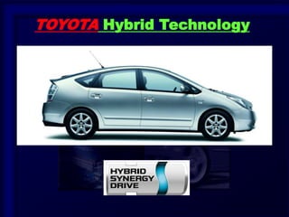
  • 3. 3 What is the Hybrid Vehicle?
  • 4. 4 CO2 Concentration 500 300 260 600 400 (ppmv) 1200 1400 1600 1800 2000 2100 What is the Hybrid Vehicle? Why is the hybrid vehicle necessary? Low fuel consumption and low CO2 emission vehicle is required Increase Automobile market Expanding Energy Consumption 2006 1970
  • 5. 5 What is the Hybrid Vehicle? Why is the hybrid vehicle necessary? – Hybrid technology is the core for eco-car development •Low fuel consumption •Low CO2 emission THS II FCHV THS Ultimate eco-car CNG DPR DPNR Common-rail VVT-i Lean Burn D-4 EV Diesel Engine Alternative Energy Gasoline Engine Electric Vehicle
  • 6. 6 What is the Hybrid Vehicle? Kind of Hybrid System – Series Hybrid System • In this system, the engine is used to supply electrical power to the motor, which then turns the wheels
  • 7. 7 What is the Hybrid Vehicle? Kind of Hybrid System – Parallel Hybrid System • The wheels are driven by both the engine and the motor
  • 8. 8 What is the Hybrid Vehicle? Kind of Hybrid System – THS (TOYOTA Hybrid System) • Strong points of both series/parallel systems realized in one system
  • 9. 9 What is the Hybrid Vehicle? THS II (TOYOTA Hybrid System) – Concept Higher Power Low Fuel Consumption
  • 10. 10 What is the Hybrid Vehicle? THS II (TOYOTA Hybrid System) – Hybrid vehicle realizes low fuel consumption and higher power PRIUS (NHW20) Japanese 10 – 15 Mode Fuel Efficiency (km/L) 0 – 100 km/h Acceleration (sec.) Good Acceleration Good Fuel Economy PRIUS (NHW11) Corolla (1.3L) Corolla (1.5L) CAMRY (2.4L) Tradeoff between performance and fuel economy in conventional vehicle
  • 11. 11 What is the Hybrid Vehicle? Driving Method – The vehicle can run on gasoline only, and does not need to be recharge – If the battery charge drops, the engine drives the generator, which recharges the battery
  • 12. 12 What is the Hybrid Vehicle? Driving Method – The vehicle may be driven while the “READY” light is ON – The engine will stop while the vehicle is stopped, in order to improve fuel economy – The engine starts up automatically after the vehicle starts off
  • 13. 13 THS II (TOYOTA Hybrid System) PRIUS [NHW20]
  • 14. 14 THS II (TOYOTA Hybrid System) Main Component Location HV Battery Engine Inverter Hybrid Transaxle •Generator (MG1) •Motor (MG2) •Power-dividing Mechanism Click Movie
  • 15. 15 MOVIE Shift Lever Parking Switch Shift Lever Main Component Location THS II (TOYOTA Hybrid System)
  • 16. 16 THS II (TOYOTA Hybrid System) System Diagram HV Battery Brake Actuator Auxiliary Battery Electric A/C Compressor A/C Inverter DC – DC Converter SMR1, 2 and 3 Boost Converter MG1 MG2 Hybrid Transaxle Inverter Engine Shift Position Sensor (Shift, Select) Accelerator Pedal Position Sensor EV Mode Switch Speed Sensors CAN Engine ECU Skid Control ECU Battery ECU DLC3 HV ECU Click here to see operation of shift lever
  • 17. 17 THS II (TOYOTA Hybrid System) Outline – Compression from conventional vehicle Item Conventional Vehicle THS II Note for THS II Power Source Engine •Engine •Motor •Generator •Motor drive is possible (Engine OFF) •Engine motive force is divided for drive and electric generation Trans- mission •A/T •M/T Power Splitting Device •Divide the engine, motor and generator power •Function as CVT Brake Hydraulic Brake •Hydraulic Brake •Regenerative Brake Cooperative control between hydraulic and regenerative brake Battery 12V Battery •12V Battery •201.6V Battery High-voltage supply for motor drive Power Train Control Engine ECU •HV ECU •Engine ECU •Inverter Controls the engine, motor and generator
  • 18. 18 THS II (TOYOTA Hybrid System) Outline – System operation Start-off Normal Driving Acceleration Deceleration Stop Electric motor only Motor and Engine Motor and Engine (additional power drawn from battery) Battery charging Engine automatically shuts off
  • 19. 19 THS II (TOYOTA Hybrid System) 1NZ-FXE Engine – 1.5 liter, In-line 4-cylinder, 16-valve DOHC, gasoline engine 1NZ-FXE X = Atkinson Cycle
  • 20. 20 THS II (TOYOTA Hybrid System) Hybrid Transaxle – Includes AC 500V motor, generator and power- dividing mechanism – Uses a continuously variable transmission mechanism to achieve smooth and quiet operations MG1 MG2 Power-dividing Mechanism
  • 21. 21 THS II (TOYOTA Hybrid System) HV Battery – Full sealed nickel metal hydride (Ni-MH) battery – DC 201.6V – Located behind the rear seat
  • 22. 22 THS II (TOYOTA Hybrid System) Inverter Assembly – Inverter • DC  AC high voltage – Variable-voltage System • DC 200V stepped up to Max. DC 500V – DC-DC Converter • DC 200V stepped down to DC 12V – A/C Inverter • DC  AC to drive the A/C compressor
  • 23. 23 THS II (TOYOTA Hybrid System) Brake System – ECB (Electrically Controlled Brake) – Hydraulic brake pressure is controlled by electrical signal and cooperate regenerative brake Skid Control ECU Vehicle Condition Driver’s Demand HV ECU Regenerative Brake Control Hydraulic Brake Control
  • 24. 24 THS II (TOYOTA Hybrid System) Steering System – EPS (Electric Power Steering) is used EPS ECU EPS Motor
  • 25. 25 THS II (TOYOTA Hybrid System) Air Conditioning System – Compact, high-performance scroll compressor driven by motor Electric Inverter Compressor
  • 26. 26 THS II (TOYOTA Hybrid System) Multi Display – Energy Monitor
  • 27. 27 THS II (TOYOTA Hybrid System) Multi Display – Fuel consumption indicator
  • 28. 28 THS II (TOYOTA Hybrid System) Auxiliary Battery (12V) – Auxiliary battery supplies power to headlights, audio, and all ECUs – Sealed-type battery is used Auxiliary Battery
  • 29. 29 THS II (TOYOTA Hybrid System) Power Cable – Orange-colored wire harness / connector High-voltage circuit High-voltage Wire Harness High-voltage Wire Harness
  • 30. 30 THS II (TOYOTA Hybrid System) Service Plug – Shut off the high-voltage circuit Caution: Wear insulated gloves when disconnecting / connecting the service plug to prevent against electrical shock Service Plug
  • 32. 32 Engine Atkinson Cycle – The “X” of the 1NZ-FXE indicates the use of the Atkinson cycle, the principle applied for this vehicle’s engine Atkinson cycle High thermal efficiency 1NZ-FXE (PRIUS)
  • 33. 33 Engine Overview – Atkinson cycle Compression Stroke < Expansion Stroke High thermal efficiency Compression Expansion
  • 34. 34 Engine Overview – Atkinson cycle • Depending on the driving condition, the cylinder volume is varied by VVT-i Valve Timing (Intake Valve) TDC BDC 72º 105º VVT-i Operation Cylinder Volume 105º 72º 90º
  • 35. 38 Engine Overview – Specifications Item 1NZ-FXE (’04 PRIUS) 1NZ-FE (Corolla) No. of Cylinders & Arrangement 4-Cylinder, in-line  Valve Mechanism 16-Valve DOHC, Chain Drive, VVT-I  Displacement cm3 (cu. in.) 1497 (91.3)  Bore x Stroke mm (in.) 75.0 x 84.7 (2.95 x 3.33)  Compression Ratio 13.0 10.5 Max. Output EEC (-W, -Q) 57 kW @ 5000 rpm 78 kW @ 6000 rpm Max. Torque EEC (-W, -Q) 115 N·m@ 4200 rpm 145 N·m@ 4200 rpm Valve Timing Intake Open 18 - -15 BTDC 42 - -2 BTDC Close 72 - 105 ABDC 10 - 50 ABDC Exhaust Open 34 BBDC 42 BBDC Close 2 ATDC  Emission Regulation STEP IV STEP III
  • 36. 39 Engine Overview – Engine compartment Radiators (for engine and inverter) are one piece Drive belt simply layout TOYOTA Genuine Super LLC
  • 37. 40 Engine Overview – Interior 32-bit engine ECU with CAN communication Non-contact type accelerator pedal position sensor
  • 39. 42 Shape is changed to weight reduction 223g (Corolla)  194g (Prius) Piston skirt portion is reduced to friction reduction New resin coat to friction reduction Engine Engine Proper – Piston • Lightweight and low friction Corolla Prius
  • 40. 43 Engine Piston Ring Cross section Tension Thickness Others Top Ring Inner Bevel Type 4.2 N  3 N 1.2 mm (0.047 in.)  0.8 mm (0.031 in.) PVD coat is used to improve wear resistance Second Ring Taper Type 3.3 N  3 N 1.2 mm (0.047 in.)  1.0 mm (0.039 in.) Steel material is used to improve wear resistance Oil Ring 2 Piece Type 17 N  8 N 2.0 mm (0.079 in.)  1.5 mm (0.059 in.) - Corolla  Prius  Engine Proper • Piston Ring – Lower tension and thinner piston ring is used for friction reduction
  • 41. 44 Engine Throttle Body (ETCS-i) Throttle valve is controlled by the HV ECU. ETCS-i also controls the cruise control system.
  • 42. 45 Engine Radiator (for engine) Radiator (for Inverter) Front Drain Plug (for engine)  Cooling System Radiators (for engine and inverter) are one piece
  • 43. 46 Engine Coolant Heat Storage System – General • This system reduces the amount of adhesion of fuel on the intake port wall after engine starting Hot coolant in the tank Before engine start Hot coolant to cylinder head Heated Amount of adhesion of fuel is reduced after engine start
  • 44. 47 Engine Coolant Heat Storage System – Components Coolant Heat Storage Tank Outlet Temp. Sensor Engine Coolant Temp. Sensor Coolant Heat Storage Water Pump Water Valve Water Pump (for Heater) Coolant Heat Storage Tank to / from heater core Reverse Side
  • 45. 48 Engine Coolant Heat Storage System – Operation • Engine running (w/o storage operation) Cylinder Block Water Pump Water Pump Heater Core Cylinder Head OF F Water Valve
  • 46. 49 Engine Coolant Heat Storage System – Operation • Storage operation (during engine running) Cylinder Block Water Pump Water Pump Heater Core Cylinder Head OF F Hot coolant is stored Water Valve
  • 47. 50 Engine Coolant Heat Storage System – Operation • Storage operation (during engine running)  Operation chart Warm-up Others Storage operation (during engine running) [Max.: 4 times] Meets start conditions Meets stop conditions Engine Starting Tank coolant temp. is 90 °C (194 °F) or more Storage is Completed Confidential
  • 48. 51 Engine Coolant Heat Storage System – Diagnosis • DTCs for Coolant Heat Storage System DTC No. Detection Item DTC No. Detection Item P1115 Coolant temp. sensor circuit for coolant heat storage system P1122 Water valve position sensor circuit low P1116 Coolant temp. sensor circuit stuck for coolant heat storage system P1123 Water valve position sensor circuit high P1117 Coolant temp. sensor circuit low for coolant heat storage system P1150 Coolant Path Clog Up for Coolant Heat Storage System P1118 Coolant temp. sensor circuit high for coolant heat storage system P1151 Coolant Heat Storage Tank P1120 Water valve position sensor circuit P2601 Coolant pump control circuit range / performance P1121 Water valve position sensor circuit stuck P2610 ECM / PCM internal engine off timer performance
  • 49. 52 Engine Coolant Heat Storage System – Service Point • Coolant Replacement  Drain engine coolant 1. Disconnect the coolant heat storage water pump connector 2. Remove the radiator cap 3. Connect a vinyl hose to drain cocks (engine, radiator, coolant heat storage tank) 4. Loosen the drain cock plugs (engine, radiator, coolant heat storage tank), and drain coolant 5. Drain the coolant in the radiator reservoir tank Caution: The coolant in coolant heat storage tank is hot even if engine and radiator are cold
  • 50. 53 Engine Coolant Heat Storage System – Service Point • Coolant Replacement  Fill engine coolant 1. Tighten the drain cock plugs and disconnect a vinyl hose (engine, radiator, coolant heat storage tank) 2. Connect a vinyl hose to the bleeder plug of radiator and insert the another side of hose to reservoir tank 3. Using 6 mm socket hexagon wrench, loosen the radiator bleeder plug from service hole 4. Fill the coolant into the radiator 5. Tighten the radiator bleeder plug and install the radiator cap 6. Fill the radiator reservoir tank with coolant to the full level 7. Connect the coolant heat storage water pump connector 8. Connect the Intelligent Tester II to DLC3 and turn to IG/ON
  • 51. 54 Engine Coolant Heat Storage System – Service Point • Coolant Replacement  Fill engine coolant 9. Perform the ACTIVE TEST of water pump (coolant heat storage water pump operates for 30 sec.) 10. Loosen the radiator bleeder plug and fill the coolant into the radiator 11. Tighten the radiator bleeder plug 12. Repeat the steps 9 to 11 until coolant cannot be added 13. Disconnect the vinyl hose 14. Warm-up engine until the thermostat is opened (inspection mode) 15. Stop the engine, and wait until the coolant gets cold 16. Fill the coolant into the radiator 17. Repeat the step 14 to 16 until coolant level stops going down 18. Check DTC and clear the DTC which relates to the water pump
  • 52. 55 Engine Fuel System (Vapor reducing fuel tank) Reduce the amount of fuel vapors released when vehicle is parked.
  • 53. 56 Engine Fuel System (Vapor reducing fuel tank) It is composed of two parts: a metal outer tank, and a plastic membrane inside the fuel tank. NOTE: Normal tank capacity is 45 liters; tank capacity decreases by 5 liters at –10°C. Click! zoom
  • 54. 58 Engine Fuel System (Vapor reducing fuel tank) Fuel Sender Gauge Sub-tank is installed inside the fuel tank, inside which a fuel pump and sender gauge are attached. Sub-tank Fuel Sender Gauge
  • 55. 59 Engine Fuel System (Vapor reducing fuel tank) Fuel Sender Gauge The fuel pump and sender gauge can not be removed from the fuel tank. If the pump or gauge malfunctions Replace the tank assembly
  • 56. 60 Engine Drive Belt System – A/C compressor pulley is not existing – Simply belt layout A/C compressor pulley is not existing Water Pump Pulley Crank Pulley Idler Pulley Adjust Bolt
  • 58. 62 Hybrid Transaxle Overview – P112 type – Components: • MG (Motor Generator) 1 • MG (Motor Generator) 2 • Power-dividing Mechanism (Planetary Gears) • Reduction Mechanism • Differential Mechanism – Fluid type: ATF WS – Capacity: 3.8 liters
  • 59. 63 Hybrid Transaxle Overview – P112 type MG2 MG1 Planetary Gears Chain-drive Sprocket
  • 60. 64 Hybrid Transaxle Overview – P112 type Counter Drive Gear Final Drive Pinion Gear Counter- driven Gear Final Ring Gear Chain-driven Sprocket Reduction Mechanism Differential Mechanism
  • 61. 65 Hybrid Transaxle MG1 / MG2 – Compact and lightweight, highly efficient AC500V motor generator MG2 MG1
  • 62. 66 Hybrid Transaxle MG1 – Main operations  Generator – When engine starting  Starter MG1 Stator Coil Rotor Speed Sensor
  • 63. 67 Hybrid Transaxle MG2 – When driving  Main power to engine power (Starting off) or provides supplementary – When braking  Converts kinetic energy to electrical energy MG2 Stator Coil Rotor Speed Sensor
  • 64. 68 Hybrid Transaxle Speed Sensor (Resolver) – Detects position, speed and direction of MG1 / MG2 rotors Speed Sensor (for MG1) Speed Sensor (for MG2)
  • 65. 69 Hybrid Transaxle Transaxle Damper – Installed at location of conventional clutch Reduces shock which occurs when kinetic energy is transmitted
  • 66. 70 Hybrid Transaxle Cooling System – Cooling circuit is used for both MG1 / MG2 – Separate cooling system from engine Reservoir Pump MG1 / 2 Radiator Inverter Reservoir Tank Radiator Electric Water Pump
  • 67. 71 Hybrid Transaxle Oil Pump – Forced lubrication system via trochoid pump used to lubricate main shaft bearings – Oil pump functions when engine is being driven Oil Pump
  • 68. 72 Hybrid Transaxle Mayor Different with Prius Generation III
  • 70. 74 Inverter Assembly Components – Inverter • DC  AC high voltage – Variable-voltage System • DC201.6V stepped up to max. DC500V – DC-DC Converter • DC201.6V stepped down to DC 12V – A/C Inverter • DC  AC to drives the A/C compressor
  • 71. 75 Inverter Assembly Components HV Battery Inverter Assembly A/C Inverter Variable- voltage System MG1 MG2 Inverter DC - DC Converter
  • 72. 76 Inverter Assembly Variable-voltage System – DC 201.6V  Max. DC 500V conversion HV Battery DC 201.6V DC500V Variable- voltage System •IPM (IGBT) •Reactor Max. DC 500V   DC 201.6V Inverter Assembly AC500V MG2 : Discharge : Charge MG1 Inverter (IPM)
  • 73. 77 Inverter Assembly Inverter Operation – Motor control Motor Torque is controlled by the current value Motor Speed is controlled by the frequency Low Torque High Torque Low Speed High Speed
  • 74. 78 Inverter Assembly DC – DC Converter – DC201V  DC 12V DC 201.6V DC – DC Converter Inverter Assembly Auxiliary Battery DC 12V DC  AC AC 201.6V  AC 12V AC  DC MG1 MG2 HV Battery Inverter Variable- voltage System
  • 75. 79 Inverter Assembly A/C inverter – DC201.6V  AC201.6V conversion Electric Inverter Compressor HV ECU HV Battery A/C ECU Target Compressor Speed DC 201.6V AC 201.6V A/C Inverter DC 201.6V  AC 201.6V Inverter Assembly
  • 76. 80 Inverter Assembly Cooling System – Cooling circuit is used for inverter assembly – Separate cooling system from engine Reservoir Pump MG1 / 2 Radiator Inverter Reservoir Tank Radiator Electric Water Pump
  • 78. 82 HV Battery Assembly Power Supply – The HV battery supplies power to MG1 / MG2 – The auxiliary battery supplies power to HV ECU and Engine ECU (all ECU) – When both are functioning properly, the vehicle will start HV Battery (DC 201.6V) Auxiliary Battery (DC 12V)
  • 80. 84 HV Battery Assembly Battery Module – Nickel metal hydride (Ni-MH) battery (1.2V x 6 cells) x 28 modules = 168 cells = DC 201.6 V 28 Module Module (1.2V x 6 cells)
  • 81. 85 HV Battery Assembly Battery ECU – Maintains control of HV battery SOC (State of charge) – Ensures battery capability Service Plug Temp. Sensors (Thermistor) Battery Cooling Fan Motor HV Battery Current Sensor Voltage x 14 + - Temp. x 4 Battery ECU SOC Control Cooling Fan Control Electrical Leakage Detection for High-voltage System Diagnosis Function for HV Battery HV Battery Condition Detection •HV ECU •Engine ECU •A/C ECU CAN Battery Cooling Fan Relay Battery Cooling Fan Controller
  • 82. 86 HV Battery Assembly Battery ECU – Controls SOC to match THS characteristics – The SOC is maintained at approx, 60%. A margin is given for further recharging via regenerative braking – Sends requests to HV ECU to obtain desired SOC
  • 83. 87 HV Battery Assembly SOC Control – When the SOC is dropped, battery ECU sends the “Charge Request” signal to HV ECU Battery ECU HV Battery Engine Drive Charge Voltage (SOC) SOC Charge Request Power Request Charging Control HV ECU Engine ECU MG1
  • 84. 88 HV Battery Assembly SMR (System Main Relay) – Turns ON / OFF the high-voltage circuit SMR1 SMR2 SMR3
  • 85. 89 HV Battery Assembly SMR – Shutdown control READY OFF At Collision Interlock Switch OFF (Service plug grip disconnection, Inverter cover open)
  • 86. 90 HV Battery Assembly Service Plug – Shut off the high voltage circuit manually Service Plug
  • 87. 91 HV Battery Assembly Auxiliary Battery – Auxiliary battery supplies power to headlights, audio, and all ECUs Auxiliary Battery
  • 88. 92 HV Battery Assembly Auxiliary Battery – Sealed-type battery is used Notice: Refrain from quick charging Because the battery fluid cannot be replenished Never use an ordinary battery
  • 89. 93 HV Battery Assembly Auxiliary Battery – Jump Start Terminal • ”+” terminal of auxiliary battery for jump start is used Jump Start Terminal
  • 90. 94 Auxiliary Battery – Jump Start Procedure Auxiliary Battery Special Notes on Service Positive Terminal Negative Terminal Click Movie
  • 92. 96 THS II Operation Components Generator (MG1) HV Battery Engine Motor (MG2) Inverter Power-dividing Device Differential Mechanism
  • 93. 97 THS II Operation Power-dividing Mechanism (Planetary Gears) – Sun gear: MG1 – Planetary Carrier: Engine – Ring Gear: MG2 (Front Wheel) MG1 MG2 Engine To Front Wheel Chain Power-dividing Mechanism
  • 94. 98 Unit Planetary gear Unit Planetary gear Ring Gear Planetary Carrier Sun Gear Perangkat Pembagi Power
  • 95. 99 Bagan Nomographic Arah Rotasi + - Mome n + Discharge (Motor) Charge (Generator) - Charge (Generator) Discharge (Motor) Kondisi MG1, MG2
  • 96. 100 Bagan Nomographic Prinsip Kerja-1 Sun gear: fixed (tertahan) Ring gear: berputar (input) Planetary carrier: ?  Referensi ke bagan Klik di atas untuk melihat film (movie)
  • 97. 101 Bagan Nomographic Prinsip Kerja-2 Planetary carrier: fixed (tertahan) Ring gear: berputar (input) Sun gear: ?  Referensi ke bagan Klik di atas untuk melihat film (movie)
  • 98. 102 THS II Operation Engine Starting and Idling Click! Movie Vehicle Speed Click! animasi
  • 99. 103 Menghidupkan Mesin Menghidupkan Mesin MG1 bekerja sebagai motor starter  Referensi ke bagan
  • 100. 104 Menghidupkan Mesin Starting Mesin dan Idling Mesin menggerakkan MG1 untuk mengisi baterai HV.  Referensi ke bagan
  • 101. 105 THS II Operation Vehicle Starting Off Vehicle Speed Click! Movie Click! animasi
  • 102. 106 Kendaraan Mulai Berjalan  Referensi ke bagan Starting Off-1 Hanya MG2 yang digunakan dalam beban ringan/ akselerasi ringan.
  • 103. 107 Kendaraan Mulai Berjalan  Referensi ke bagan Starting Off-2 MG1 bekerja untuk menghidupkan mesin saat dibutuhkan tambahan power.
  • 104. 108 Kendaraan Mulai Berjalan  Referensi ke bagan Starting Off-3 Mesin menggerakkan MG1 untuk membangkitkan listrik untuk MG2
  • 105. 109 Vehicle Speed THS II Operation Accelerating Under Low Load (Light Throttle) – Request more power, MG1 starts engine Click! Movie Click! animasi
  • 106. 110 Selama Merayap (Cruising): Selama Merayap (Cruising): MG2 membangkitkan listrik untuk MG1. Unit planetary gear bertindak sebagai CVT.  Referensi ke bagan
  • 107. 111 Selama Merayap (Cruising): Akselerasi Ringan MG1 membangkitkan listrik untuk MG2. MG2 menyediakan power penggerak tambahan.  Referensi ke bagan
  • 108. 112 THS II Operation Accelerating Under Heavy Load (Full Throttle) Vehicle Speed Click! Movie Click! animasi
  • 109. 113 Akselerasi Full Throttle  Referensi ke bagan Akselerasi Full Throttle
  • 111. 115 Deselerasi  Referensi ke bagan D range MG2 berperan sebagai generator untuk mengisi baterai HV.
  • 112. 116 Deselerasi B range MG1 menggerakkan mesin untuk pengereman oleh mesin.  Referensi ke bagan
  • 113. 117 THS II Operation Driving in Reverse Vehicle Speed Click! Movie Click! animasi
  • 114. 118 Pengendaraan Mundur Pengendaraan Mundur Hanya MG2 yang digunakan untuk mundur.  Referensi ke bagan
  • 115. 119 Kontrol Motor Traction Control Mengontrol MG2 dan rem hidrolik. MG2 Traction Control Gaya Pengereman Inverter Sensor Kecepatan Kecepatan Tinggi ECU Skid Control ECU HV Sensor Kecepatan Setiap Roda Slipping
  • 116. 120 Kontrol Kontrol Bantuan Menanjak Mengontrol rem hidrolik belakang. ECU HV Traction Control Gaya Pengereman ECU Skid Control Sinyal Sensor Kecepatan MG2 dll. Mencegah kendaraan dari terguling ke belakang
  • 117. 121 THS II Operation THS-II Control – Motor Drive Mode Control (except U.S.A. model) • In this mode, the vehicle is driven by only MG2 by operating the EV Mode Switch Drive Accelerator Pedal Position Sensor Battery ECU •SOC Condition •Battery Temp. EV Mode Switch Skid Control ECU Speed Sensors Combination Meter Gateway ECU EV Mode Indicator Light HV ECU Inverter HV Battery Engine ECU
  • 118. 122 THS II Operation THS-II Control – Motor Drive Mode Control (except U.S.A. model) • EV Mode Switch is momentary type LHD Model EV Mode Switch
  • 119. 123 THS II Operation THS-II Control – Motor Drive Mode Control (except U.S.A. model) • Operation conditions EV Mode Normal Push EV mode canceling conditions •EV mode switch is pushed •HV battery SOC drops •HV battery temp. is low or high •Engine is warming up •Vehicle speed exceeds the specified speed •The accelerator pedal position angle exceeds the specified value or
  • 121. 125 ECB (Electronically Controlled Brake) General – The total brake force provided by both hydraulic and regenerative brakes matches the braking power required Regenerative Brake Hydraulic Brake
  • 122. 126 ECB (Electronically Controlled Brake) ECB Operation – Hydraulic brake pressure is generated electrically (brake by wire) Conventional Vehicle ECB Vehicle Sensor Skid Control ECU Control Brake Force Generation Brake Force Generation
  • 124. 128 Indicator and Warning Combination Meter – READY light indicates that the vehicle is ready to drive Ready Light
  • 125. 129 Indicator and Warning Multi Display – Energy monitor shows the energy flow
  • 126. 130 Indicator and Warning Multi Display – Warning display • Warning marks Automatic Headlight Leveling System Warning Oil Pressure Warning High Engine Coolant Temperature Warning Hybrid System Abnormal HV Battery Warning Discharge Warning EPS Warning
  • 127. 131 Indicator and Warning Multi Display – Warning message
  • 129. 133 Other Systems General – Engine is operated intermittently, so power steering and A/C compressor uses electric power EPS (Electric Power Steering) Electric Inverter Compressor
  • 130. 134 Other Systems EPS (Electric Power Steering) – Column assist type EPS is used Column Assist Type EPS Reduction Mechanism EPS ECU DC Motor (12V) Torque Sensor
  • 131. 135 Other Systems Air Conditioning – Service Point • Don’t use the compressor oil other than ND11
  • 133. 137 Service Point Inspection Mode – In the inspection mode, engine is continuously operated (P range) and motor TRC is turned off Note: Other hybrid vehicle has several types of inspection mode. For derails, please refer to the repair manual. Mode Vehicle Condition Purpose Transferring Procedure Inspection Mode- 2WD Inspection (Inspection Mod1) •Keeps engine running (P range) •Motor TRC is OFF •Exhaust gas test •Engine adjusting •Speedometer test •Manual procedure •Intelligent tester (Active Test) Inspection Mode- 2WD Chassis- Dynamo (Inspection Mod2) Motor TRC is OFF Speedometer test (chassis dynamometer) Intelligent tester (Active Test)
  • 134. 138 Service Point Inspection Mode – Manual procedure OFF  IG-ON Depress twice Depress twice Depress twice Accelerator Pedal IG-ON  READY with brake Change the power mode to OFF  inspection mode is canceled within 60 seconds Click Movie
  • 135. 139 Service Point High-voltage Wire Harness – All high-voltage wire harness and connectors are colored orange High-voltage Wire Harness High-voltage Wire Harness Click Movie
  • 136. 140 Service Point High-voltage Wire Harness – Use a megohmmeter to measure the insulation resistance (Standard: 2  10 M) Notice: If you use the 1000V range, it causes the breakdown of the parts Basically use the 500V range It cannot check the insulation resistance correctly by the TOYOTA Electrical Tester Megohmmeter
  • 137. 141 Service Point High-voltage Wire Harness – Risk of electric shock Case Condition Risk of Electric Shock Touch the high-voltage + side No risk Touch the body (high-voltage - side) when there is a electrical leakage No risk Touch the high-voltage + side when there is a electrical leakage Possibility of electric shock Touch the high-voltage + and - side Electric shock !
  • 138. 142 Service Point Safety Precautions – Before servicing the high voltage area • Make sure to perform the followings; 1. Use the "CAUTION: HIGH VOLTAGE. DO NOT TOUCH DURING OPERATION" sign 2. Turn the power mode to off 3. Remove the key from key slot and carry the key 4. Disconnect auxiliary battery negative terminal 5. Check the insulated gloves 6. Remove the service plug 7. Wait 5 min. or more 8. Measure the inverter terminal voltage (0V check)
  • 139. 143 Service Point Safety Precautions 5. Before servicing the high voltage area Wait 10 minutes or more to discharge high-voltage condenser in the inverter 5 min. High-voltage Condenser Discharge Service plug disconnection Elect- ricity 0V Inverter Assembly
  • 140. 144 Service Point Safety Precautions – Before servicing the high voltage area 1.Use the "CAUTION: HIGH VOLTAGE. DO NOT TOUCH DURING OPERATION" sign to notify other engineers
  • 141. 145 Service Point Safety Precautions – Before servicing the high voltage area 5.Check the insulated gloves Not cracked, ruptured, torn, or damaged Not wet
  • 142. 146 Service Point Safety Precautions – Before servicing the high voltage area 6.Remove the service plug Remove before servicing Service Plug
  • 143. 147 Service Point Safety Precautions – Before servicing the high voltage area 8.Measure the inverter terminal voltage (0V check) Inverter Assembly Between 3 phases 3 phases and body ground
  • 144. 148 Service Point Safety Precautions – During servicing the high voltage area • Insulate the tools by vinyl tape Insulated Vinyl Tape
  • 145. 149 Service Point Safety Precautions – During servicing the high voltage area • Insulate the disconnected high-voltage connector with insulated vinyl tape Insulated Vinyl Tape
  • 146. 150 Service Point Safety Precautions – During servicing the high voltage area • Non-reusable nut is used to the installation of high voltage line Example of use Non- reusable Wire x SMR Junction Block x Module New Used
  • 147. 151 Service Point Safety Precautions – After servicing the high voltage area • Before reinstalling the service plug, check again the following You have not left a part or tool inside The high-voltage terminal nuts and screws are properly tightened The connectors are correctly connected
  • 148. 152 Service Point Safety Precautions – After servicing the high voltage area • Be sure to install the service plug before starting the hybrid system READY ON After servicing Installation Vehicle damages
  • 149. 153  HV Battery Warning Light illuminates  Can not READY ON  DTC P3000-389 (HV Battery Malfunction) is detected Service Point Response When The HV Battery (201.6V) Runs Out – Vehicle conditions when HV battery low voltage
  • 150. 154 THS Charger Service Point Response When The HV Battery (201.6V) Runs Out – Charge the HV Battery using THS Charger Note: THS charger is the recommended tool THS Charger
  • 151. 155 Service Point Battery Pack Removal / Installation – If the HV battery electrolyte leaks, don’t touch it Don’t touch the battery electrolyte ! Boric Acid Solution Neutralize battery electrolyte Boric Acid (800 g) Water (20 liters)
  • 152. 156 Service Point Towing Notice: If there is a electrical leakage, motor regenerates the electricity by wheel rotation

Editor's Notes

  1. PT. TAM - TSD Training Center
  2. PT. TAM - TSD Training Center
  3. PT. TAM - TSD Training Center
  4. PT. TAM - TSD Training Center
  5. PT. TAM - TSD Training Center
  6. PT. TAM - TSD Training Center
  7. PT. TAM - TSD Training Center
  8. PT. TAM - TSD Training Center
  9. PT. TAM - TSD Training Center
  10. PT. TAM - TSD Training Center
  11. PT. TAM - TSD Training Center
  12. PT. TAM - TSD Training Center
  13. PT. TAM - TSD Training Center
  14. PT. TAM - TSD Training Center
  15. PT. TAM - TSD Training Center
  16. PT. TAM - TSD Training Center
  17. PT. TAM - TSD Training Center
  18. PT. TAM - TSD Training Center
  19. PT. TAM - TSD Training Center
  20. PT. TAM - TSD Training Center
  21. PT. TAM - TSD Training Center
  22. PT. TAM - TSD Training Center
  23. PT. TAM - TSD Training Center
  24. PT. TAM - TSD Training Center
  25. PT. TAM - TSD Training Center
  26. PT. TAM - TSD Training Center
  27. PT. TAM - TSD Training Center
  28. PT. TAM - TSD Training Center
  29. PT. TAM - TSD Training Center
  30. PT. TAM - TSD Training Center
  31. PT. TAM - TSD Training Center
  32. PT. TAM - TSD Training Center
  33. PT. TAM - TSD Training Center
  34. PT. TAM - TSD Training Center
  35. PT. TAM - TSD Training Center
  36. PT. TAM - TSD Training Center
  37. PT. TAM - TSD Training Center
  38. PT. TAM - TSD Training Center
  39. PT. TAM - TSD Training Center
  40. PT. TAM - TSD Training Center
  41. PT. TAM - TSD Training Center
  42. PT. TAM - TSD Training Center
  43. PT. TAM - TSD Training Center
  44. PT. TAM - TSD Training Center
  45. PT. TAM - TSD Training Center
  46. PT. TAM - TSD Training Center
  47. PT. TAM - TSD Training Center
  48. PT. TAM - TSD Training Center
  49. PT. TAM - TSD Training Center
  50. PT. TAM - TSD Training Center
  51. PT. TAM - TSD Training Center
  52. PT. TAM - TSD Training Center
  53. PT. TAM - TSD Training Center
  54. PT. TAM - TSD Training Center
  55. PT. TAM - TSD Training Center
  56. PT. TAM - TSD Training Center
  57. PT. TAM - TSD Training Center
  58. PT. TAM - TSD Training Center
  59. PT. TAM - TSD Training Center
  60. PT. TAM - TSD Training Center
  61. PT. TAM - TSD Training Center
  62. PT. TAM - TSD Training Center
  63. PT. TAM - TSD Training Center
  64. PT. TAM - TSD Training Center
  65. PT. TAM - TSD Training Center
  66. PT. TAM - TSD Training Center
  67. PT. TAM - TSD Training Center
  68. PT. TAM - TSD Training Center
  69. PT. TAM - TSD Training Center
  70. PT. TAM - TSD Training Center
  71. PT. TAM - TSD Training Center
  72. PT. TAM - TSD Training Center
  73. PT. TAM - TSD Training Center
  74. PT. TAM - TSD Training Center
  75. PT. TAM - TSD Training Center
  76. PT. TAM - TSD Training Center
  77. PT. TAM - TSD Training Center
  78. PT. TAM - TSD Training Center
  79. PT. TAM - TSD Training Center
  80. PT. TAM - TSD Training Center
  81. PT. TAM - TSD Training Center
  82. PT. TAM - TSD Training Center
  83. PT. TAM - TSD Training Center
  84. PT. TAM - TSD Training Center
  85. PT. TAM - TSD Training Center
  86. PT. TAM - TSD Training Center
  87. PT. TAM - TSD Training Center
  88. PT. TAM - TSD Training Center
  89. PT. TAM - TSD Training Center
  90. PT. TAM - TSD Training Center
  91. PT. TAM - TSD Training Center
  92. PT. TAM - TSD Training Center
  93. PT. TAM - TSD Training Center
  94. PT. TAM - TSD Training Center
  95. PT. TAM - TSD Training Center
  96. PT. TAM - TSD Training Center
  97. PT. TAM - TSD Training Center
  98. PT. TAM - TSD Training Center
  99. PT. TAM - TSD Training Center
  100. PT. TAM - TSD Training Center
  101. PT. TAM - TSD Training Center
  102. PT. TAM - TSD Training Center
  103. PT. TAM - TSD Training Center
  104. PT. TAM - TSD Training Center
  105. PT. TAM - TSD Training Center
  106. PT. TAM - TSD Training Center
  107. PT. TAM - TSD Training Center
  108. PT. TAM - TSD Training Center
  109. PT. TAM - TSD Training Center
  110. PT. TAM - TSD Training Center
  111. PT. TAM - TSD Training Center
  112. PT. TAM - TSD Training Center