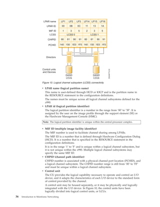
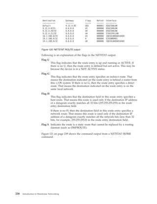
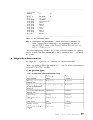
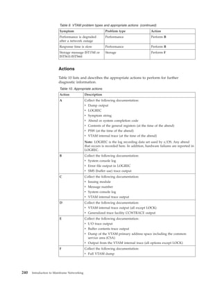
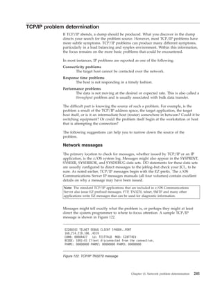
Learn about Networking on z/OS. This part of the z/OS basic skills information center is intended to provide information systems personnel with the background knowledge and skills necessary to begin using the basic communications facilities of a mainframe based system. It provides a broad understanding of networking principles and the hardware and software components necessary to allow the mainframe to participate in a high volume data communications network. For more information on IBM System z, visit http://ibm.co/PNo9Cb.
Visit the official Scribd Channel of IBM India Smarter Computing at http://bit.ly/VwO86R to get access to more documents.
This presentation discusses the principles of IP Routing as they apply to z/OS, the z/OS implementation of static routing through the TCP/IP profile, and dynamic routing with OMPROUTE.
TN3270 Access to Mainframe SNA ApplicationszOSCommserver
This presentation presents the basics of the TN3270 protocol, and discusses how to configure the TN3270 server provided with z/OS Communications Server.
I Didn't Know You Could Do That with zOS.pdfMarna Walle
1. The document discusses several new and updated features in recent z/OS releases: controlling GDGE maximum limits, using z/OS UNIX commands on MVS data sets, sending redacted dumps from z/OSMF Incident Log using Data Privacy for Diagnostics, installing individual products using z/OSMF portable software instances, viewing SNA application activity via the Function Registry, managing resource shortages with JES2's Emergency Subsystem, and a planned z/OS UUID capability.
2. The topics provide insights into system usage and improvements for problem diagnosis, software management, and urgent system tasks.
3. Users can benefit from these features to better understand their systems, install software easily, and respond to
TCP/IP Stack Configuration with Configuration Assistant for IBM z/OS CSzOSCommserver
An overview of using the IBM Configuration Assistant for z/OS Communications Server, a z/OSMF plug-in, to configure the Communications Server TCP/IP stack. Includes updates on new functions for importing existing configuration and generating OBEY files for dynamic configuration modification, which have shipped or are shipping in new function PTFs since the General Availability of V2R2.
Communications Server provides TCP/IP and SNA connectivity and services on z/OS. It combines the prior VTAM and TCP/IP products and provides common networking functions. Applications can access networks using SNA APIs, sockets APIs, or standard TCP/IP applications. Communications Server supports both SNA and TCP/IP protocols and their integration.
This slide contains all the basic concepts of ISPF. It's giving the simple and easy step to get the knowledge of Interactive system productivity facility. If u like it then give me feedback on email anilbharti85@gmail.com Thanks v much.
A K Bharti
z/OS V2R2 Communications Server OverviewzOSCommserver
This presentation provides an overview of features in the upcoming z/OS V2R2 Communications Server. Features to be discussed include:
- Improved scalability with 64-bit support for the TCP/IP stack
- Shared Memory Communications over RDMA (SMC-R) adapter virtualization
- Security improvements such as AT-TLS and FTP support for TLS session reuse
- The ability to configure the TCP/IP stack via the IBM Configuration Assistant for z/OSMF
- Support for CICS transaction tracking
- TCP/IP autonomics enhancements
… and many more features!
z16 zOS Support - March 2023 - SHARE in Atlanta.pdfMarna Walle
The document provides information about installing and configuring z/OS for the IBM z16 server. Key points include:
- z/OS V2.3 or higher is required for base support of the z16, while higher releases provide more capabilities. PTFs are categorized for required, exploitation, and recommended functions.
- SMP/E's REPORT MISSINGFIX command can identify missing z16 PTFs using fix categories rather than manually checking the PSP bucket.
- General upgrade best practices include having the latest z/OS service installed before the hardware, keeping changes limited in scope, and reviewing restrictions.
- The z/OSMF upgrade workflow provides an interactive guide to upgrading to
The document discusses implementing a Parallel Sysplex which couples multiple z/OS systems together using hardware and software services. Key steps include defining coupling facility structures, configuring XCF signalling paths using CTCs or a coupling facility, formatting and configuring sysplex couple data sets, and defining CFRM policies to manage coupling facility resources.
DB2 10 & 11 for z/OS System Performance Monitoring and OptimisationJohn Campbell
This is a "One day Seminar -ODS " . The objectives of this ODS are to focus on key areas
• System address space CPU, EDM pools, data set activity, logging, lock/latch contention, DBM1
virtual and real storage, buffer pools and GBP,…
• Identify the key performance indicators to be monitored
• Provide rules-of-thumb to be applied
• Typically expressed in a range, e.g. < X-Y
• If <x,>Y, need further investigation and tuning - RED
• Boundary condition if in between - AMBER
• Investigate with more detailed tracing and analysis when time available
• Provide tuning advice for common problems
This document provides an introduction to using Job Control Language (JCL) and the System Display and Search Facility (SDSF) on IBM mainframe systems. It explains the basic components of JCL, including the JOB, EXEC, and DD statements. It also describes how to create JCL procedures, override procedure statements, and use utilities and system libraries. The document concludes by explaining how SDSF allows users to monitor jobs, view outputs, and issue commands to the operating system.
This document discusses mainframe clustering techniques including logical partitioning (LPAR), basic shared storage, channel-to-channel connections (CTC), and parallel sysplex. A parallel sysplex uses a coupling facility to connect multiple mainframes, providing data sharing and workload distribution. Geographically dispersed parallel sysplex (GDPS) extends this across data centers, with technologies like PPRC for synchronous data mirroring. GDPS includes a controlling system to automate failure recovery and switching between primary and secondary sites. Mainframe clustering maximizes availability, scalability and disaster recovery capabilities.
Upgrade to IBM z/OS V2.5 technical actionsMarna Walle
Yes, "upgrade" is the new name for these traditional "migration" sessions! This is part one of a two-part session that will be of interest to System Programmers and their managers who are upgrading to z/OS V2.5 from either z/OS V2.3 or V2.4. It is strongly recommended that you review sessions for a complete upgrade picture.
The general availability date for z/OS V2.5 was September 30, 2021.
Upgrade to IBM z/OS V2.4 technical actionsMarna Walle
Yes, "upgrade" is the new name for these traditional "migration" sessions! This is part one of a two-part session that will be of interest to System Programmers and their managers who are upgrading to z/OS 2.4 from either z/OS 2.2 or 2.3. It is strongly recommended that you review sessions for a complete upgrade picture.
The general availability date for z/OS V2.4 was September 30, 2019.
This presentation provides an overview of some of the concepts and functions associated with z/OS Communications Server's exploitation of the System z sysplex capability. This includes topics such as dynamic VIPA, sysplex distributor, and sysplex autonomics.
The document provides an overview of the Interactive System Productivity Facility (ISPF) and the Time Sharing Option (TSO) mainframe operating system. ISPF is a development toolset for z/OS that facilitates programming and end-user work by providing labeled screens and services to create dialog applications. TSO is IBM's mainframe time-sharing system, and ISPF can be seen as an extension to TSO that provides additional interactive processing capabilities. Upon completing the course, users will understand how to navigate ISPF, work with data sets, submit and monitor background jobs, and more.
DB2 for z/OS Real Storage Monitoring, Control and PlanningJohn Campbell
Just added another hot DB2 topic around DB2 for z/OS Real Storage Monitoring, Control and Planning - Check it out and make sure your system runs safely
Ramon Fried covers the following topics:
* What DMA is.
* DMA Buffer Allocations and Management.
* Cache Coherency.
* PCI and DMA.
* dmaengine Framework.
Ramon is an Embedded Linux team leader in TandemG, leading various cutting edge projects in the Linux kernel.
He has years of experience in embedded systems, operating systems and Linux kernel.
z/OS Small Enhancements - Episode 2016AMarna Walle
This presentation covers small enhancements from older z/OS releases. You might have missed little functions that are helpful, but you never knew existed! The content of each of these z/OS Small Enhancements changes every half year (Episode A and Episode B each year).
This document discusses SR-IOV (Single Root I/O Virtualization), which allows a PCIe device to appear as multiple separate devices. It describes how SR-IOV works by introducing physical functions and virtual functions. It then outlines the steps to enable SR-IOV on a Xen hypervisor, including configuring the network device, enabling virtual functions, binding VFs to the pciback driver, and assigning VFs to guest VMs. Reference links are also provided for additional information on SR-IOV and its implementation in Xen.
Linux Kernel vs DPDK: HTTP Performance ShowdownScyllaDB
In this session I will use a simple HTTP benchmark to compare the performance of the Linux kernel networking stack with userspace networking powered by DPDK (kernel-bypass).
It is said that kernel-bypass technologies avoid the kernel because it is "slow", but in reality, a lot of the performance advantages that they bring just come from enforcing certain constraints.
As it turns out, many of these constraints can be enforced without bypassing the kernel. If the system is tuned just right, one can achieve performance that approaches kernel-bypass speeds, while still benefiting from the kernel's battle-tested compatibility, and rich ecosystem of tools.
Maintec Technologies provides affordable access to latest Mainframe infrastructure for development, training, additional short term capacity increases and outsourcing needs. Leverage our Mainframe infrastructure, without investing the time, expense and manpower it would take to build your own!.
The Android booting process involves 5 stages:
1. The bootloader loads the kernel from flash memory into RAM.
2. The kernel initializes the system and loads drivers. It then launches the init process.
3. Init mounts filesystems and runs scripts to set up services. It also loads properties and launches the Zygote process.
4. Zygote preloads classes and resources. It forks to create new processes like the System Server using copy-on-write.
5. The System Server starts core system services. When complete, Android has finished booting and is ready for use.
z/OS Communications Server Technical UpdatezOSCommserver
In this session, the speakers will provide a look at new and coming features in z/OS 3.1 Communications Server. Features to be covered include:
- Networking support for z/OS containers
- Network security enhancements
- z/OS UNIX syslogd support for secure logging over TCP
- Communications Server exploitation of the IBM Function Registry for z/OS
... and more!
Introduction to IBM Shared Memory Communications Version 2 (SMCv2) and SMC-Dv2zOSCommserver
This document discusses SMC Version 2 (SMCv2) which introduces enhancements that allow SMC connections across multiple IP subnets by leveraging Routable RoCE (RoCEv2). Key points include:
- RoCEv2 allows SMC traffic to be encapsulated in UDP/IP packets, making it IP routable and no longer restricted to a single IP subnet.
- SMC-D Version 2 (SMC-Dv2) over Internal Shared Memory Version 2 (ISMv2) will be delivered for z/OS 2.4 on IBM z15 systems, allowing SMC connections across LPARs on different IP subnets.
- Future support for SMC-R
The document discusses ioremap and mmap functions in Linux for mapping physical addresses into the virtual address space. Ioremap is used when physical addresses are larger than the virtual address space size. It maps physical addresses to virtual addresses that can be accessed by the CPU. Mmap allows a process to map pages of a file into virtual memory. It is useful for reducing memory copies and improving performance of file read/write operations. The document outlines the functions, flags, and flows of ioremap, mmap, and implementing a custom mmap file operation for direct physical memory mapping.
This document provides information about networking and communication management in AIX Version 7.1. It covers topics such as mail management, TCP/IP, Basic Networking Utilities (BNU), serial communications, and the Network File System (NFS). The document is intended for both system administrators and users to help them perform tasks related to networking and communications.
The document provides information about the FPBA-01 PROFIBUS DP adapter module, including its mechanical installation, electrical installation, configuration, start-up procedures for various ABB drive products, and communication protocols. It contains sections on safety instructions, an overview of the PROFIBUS network and module components, installation steps, configuration parameters for the module and drives, examples of setting up speed and position control using different communication profiles, and details on the PROFIBUS DP protocol.
This document provides information about maintaining fiber optic links used in IBM System z processors. It discusses fiber optic cable elements, connectors, jumper cables, trunk cables, distribution panels, couplers, adapters, and test equipment. The document outlines typical link configurations and common failures. It provides procedures for problem determination, installation best practices, documentation guidelines, specifications, and worksheets for link loss calculations.
Ibm flex system and pure flex system network implementation with cisco systemsEdgar Jara
This document provides an overview and technical details about implementing a network connecting IBM PureFlex and Flex System servers to Cisco switches. It covers networking concepts from layers 1 through 3, including cabling, switches, routing protocols, and redundancy protocols. Specific IBM and Cisco networking components are discussed, such as Ethernet adapters, switches, and routing protocols like OSPF. The goal is to help users understand and troubleshoot networks combining IBM and Cisco systems.
This document provides a programming guide for the Modicon M241 logic controller. It describes the controller's hardware components and memory organization. It also explains how to configure tasks, libraries, data types, I/O modules, communication ports and other parameters. The guide consists of 16 chapters that cover the controller's features and how to connect it to a PC for programming.
This project is concerned with the
design of SoC for detecting and correcting the error which may occur in the memory unit due to
radiation in LEO (Lower Earth Orbit) and due to stuck-at faults in memory unit in space station.
The error free data is feed to the predestined processor using the serial communication protocol
(UART) and perform its function specified in the data input which is sent from the ground station.
This document provides instructions for setting up and configuring the network connection and functions of an imageRUNNER device. It includes information on optional equipment requirements, system requirements for various network functions, and step-by-step instructions for configuring settings like TCP/IP settings, E-mail/I-Fax settings, and setting up computers and servers on the network. The document is divided into chapters that cover settings common to all network protocols, using TCP/IP networks, and examples of connecting different types of computer systems to the network.
The document provides tutorials and documentation on advanced stateful features in TRex, an open source traffic generation and emulation tool. It describes how TRex can generate stateful traffic at scale, emulate layers 3-7 protocols, and provide capabilities like GTP tunneling. The tutorials cover topics like configuring stateful profiles, running simulations, automation with Python, and clustering multiple TRex clients to generate high volumes of stateful traffic.
Book - Automating with SIMATIC_ Controllers, Software, Programming, Data Comm...ItaecioJunior2
This document provides an overview of automating with SIMATIC controllers, software, programming, data communication, operator control and process monitoring. It describes the SIMATIC automation system components, including various controller hardware models from micro to modular sizes. It also covers the engineering tool STEP 7 for configuring and programming SIMATIC, the programming languages available, and concepts for creating user programs.
This document provides an overview and instructions for installing and configuring the Integrated Dell Remote Access Controller 6 (iDRAC6). It includes information on supported platforms and operating systems, installing iDRAC6 hardware and software, configuring network and user settings using the web interface, updating firmware, and advanced configurations for features like serial over LAN and multiple iDRAC controllers. The document contains information to help users get started with basic iDRAC6 setup and management as well as customize advanced functionality.
This document provides an overview and instructions for using IBM's DFSORT utility on the z/OS operating system. It discusses DFSORT's functions for sorting, merging, and copying records; describes how to invoke DFSORT using JCL; and details the various program control statements that can be used to control DFSORT's processing. The document also covers using user exit routines with DFSORT to customize its behavior.
This document provides a feature guide for Junos OS Layer 2 Wholesale for Subscriber Services. It includes an overview of broadband subscriber management basics and hardware, as well as the Junos software features that enable layer 2 wholesale services. The document describes how to configure a layer 2 wholesale network with separate routing instances and VLAN interfaces to isolate traffic for different service retailers. It also covers RADIUS configuration and VLAN tagging for layer 2 wholesale subscriber services.
Emulex - Management Mind Meld (A. Ordoubadian)Ali Ordoubadian
Converged networking combines existing local area networks (LANs) and storage area networks (SANs) into a single high-performance 10 gigabit Ethernet framework. This results in an overlap of responsibilities for network and storage administrators. The document provides an overview of key storage and networking concepts to help administrators understand changes from converged networking and how it will impact their roles, covering topics such as SANs, performance, availability, security and management.
Cisco E1200 Introduction and Configuration Adnan Khan
This document is a user guide for Linksys E-Series routers that provides setup and configuration instructions. It includes sections on basic setup instructions, connecting devices to the network, wireless security settings, port forwarding, maintenance, and specifications for various Linksys router models.
This thesis examines considerations for deploying software-defined networks (SDN) in telecommunication networks. It discusses strategies for migrating networks to allow both SDN and legacy devices to interoperate during an incremental deployment. The thesis formulates an automated process for bootstrapping newly deployed forwarding devices onto the network in an emulated environment. It also reviews solutions for programming forwarding devices, performing topology discovery, and providing secure remote management of devices located in untrusted environments.
This document provides a user manual for configuring and using the 1757-ABRIO Process Remote I/O Communication Interface Module. It describes how to configure the module using AbRioCfg software, map I/O data to tags, and access the tags from a ProcessLogix or RSLogix 5000 controller. It also provides instructions for monitoring the module operation and lists the supported 1771 remote I/O modules that can communicate over the remote I/O network.
This document is an instruction set reference manual for MicroLogix 1100 programmable controllers. It provides important safety information for solid state equipment and outlines differences compared to electromechanical devices. The manual contains revisions to firmware and features. It also includes a table of contents that lists chapters covering topics like I/O configuration, controller memory, function files, programming instructions, high-speed counter and outputs, timer and counter instructions, and compare instructions.
This IBM Redpaper provides a brief overview of OpenStack and a basic familiarity of its usage with the IBM XIV Storage System Gen3. The illustration scenario that is presented uses the OpenStack Folsom release implementation IaaS with Ubuntu Linux servers and the IBM Storage Driver for OpenStack. For more information on IBM Storage Systems, visit http://ibm.co/LIg7gk.
Visit http://bit.ly/KWh5Dx to 'Follow' the official Twitter handle of IBM India Smarter Computing.
Learn how all flash needs end to end Storage efficiency. For more information on IBM FlashSystem, visit http://ibm.co/10KodHl.
Visit http://bit.ly/KWh5Dx to 'Follow' the official Twitter handle of IBM India Smarter Computing.
Learn about vSphere Storage API for Array Integration on the IBM Storwize family. IBM Storwize V7000 Unified combines the block storage capabilities of Storwize V7000 with file storage capabilities into a single system for greater ease of management and efficiency. For more information on IBM Storage Systems, visit http://ibm.co/LIg7gk.
Visit http://bit.ly/KWh5Dx to 'Follow' the official Twitter handle of IBM India Smarter Computing.
Learn about IBM FlashSystem 840 and its complete product specification in this Redbook. FlashSystem 840 provides scalable performance for the most demanding enterprise class applications. IBM FlashSystem 840 accelerates response times with IBM MicroLatency to enable faster decision making. For more information on IBM FlashSystem, visit http://ibm.co/10KodHl.
Visit http://on.fb.me/LT4gdu to 'Like' the official Facebook page of IBM India Smarter Computing.
Learn about the IBM System x3250 M5,.The x3250 M5 offers the following energy-efficiency features to save energy, reduce operational costs, increase energy availability, and contribute to a green environment, energy-efficient planar components help lower operational costs. For more information on System x, visit http://ibm.co/Q7m3iQ.
http://www.scribd.com/doc/210746104/IBM-System-x3250-M5
This Redbook talks about the product specification of IBM NeXtScale nx360 M4. The NeXtScale nx360 M4 server provides a dense, flexible solution with a low total cost of ownership (TCO). The half-wide, dual-socket NeXtScale nx360 M4 server is designed for data centers that require high performance but are constrained by floor space. For more information on System x, visit http://ibm.co/Q7m3iQ.
http://www.scribd.com/doc/210745680/IBM-NeXtScale-nx360-M4
The IBM System x3650 M4 HD is a (1) 2-socket 2U rack-optimized server that supports up to 32 internal drives and features an innovative design for optimal performance, uptime, and dense storage. It offers (2) excellent reliability, availability, and serviceability for improved business environments. The server is (3) designed for easy deployment, integration, service, and management.
Here are the product specification for IBM System x3300 M4. This product can be managed remotely.The x3300 M4 server contains IBM IMM2, which provides advanced service-processor control, monitoring, and an alerting function. The IMM2 lights LEDs to help you diagnose the problem, records the error in the event log, and alerts you to the problem. For more information on System x, visit http://ibm.co/Q7m3iQ.
Visit http://on.fb.me/LT4gdu to 'Like' the official Facebook page of IBM India Smarter Computing.
Learn about IBM System x iDataPlex dx360 M4. IBM System x iDataPlex is an innovative data center solution that maximizes performance and optimizes energy and space efficiency. The iDataPlex solution provides customers with outstanding energy and cooling efficiency, multi-rack level manageability, complete flexibility in configuration, and minimal deployment effort. For more information on System x, visit http://ibm.co/Q7m3iQ.
http://www.scribd.com/doc/210744055/IBM-System-x-iDataPlex-dx360-M4
The IBM System x3500 M4 server provides powerful and scalable performance for business applications in an energy efficient tower or rack design. It features the latest Intel Xeon E5-2600 v2 or E5-2600 processors with up to 24 cores, 768GB RAM, 32 hard drives, and 8 PCIe slots. Comprehensive systems management tools and redundant components help ensure high availability, while its small footprint and 80 Plus Platinum power supplies reduce data center costs.
Learn about system specification for IBM System x3550 M4. The x3550 M4 offers numerous features to boost performance, improve scalability, and reduce costs. Improves productivity by offering superior system performance with up to 12-core processors, up to 30 MB of L3 cache, and up to two 8 GT/s QPI interconnect links. For more information on System x, visit http://ibm.co/Q7m3iQ.
Learn about IBM System x3650 M4. The x3650 M4 is an outstanding 2U two-socket business-critical server, offering improved performance and pay-as-you grow flexibility along with new features that improve server management capability. For more information on System x, visit http://ibm.co/Q7m3iQ.
http://www.scribd.com/doc/210741926/IBM-System-x3650-M4
Learn about the product specification of IBM System x3500 M3. System x3500 M3 has an energy-efficient design which works in conjunction with the IMM to govern fan rotation based on the readings that it delivers. This saves money under normal conditions because the fans do not have to spin at high speed. For more information on System x, visit http://ibm.co/Q7m3iQ.
http://www.scribd.com/doc/210741626/IBM-System-x3500-M3
Learn about IBM System x3400 M3. The x3400 M3 offers numerous features to boost performance and reduce costs, x3400 M3 has the ability to grow with your application requirements with these features. Powerful systems management features simplify local and remote management of the x3400 M3. For more information on System x, visit http://ibm.co/Q7m3iQ.
Visit http://on.fb.me/LT4gdu to 'Like' the official Facebook page of IBM India Smarter Computing.
Learn about IBM System 3250 M3 which is a single-socket server that offers new levels of performance and flexibility
to help you respond quickly to changing business demands. Cost-effective and compact, it is well suited to small to mid-sized businesses, as well as large enterprises. For more information on System x, visit http://ibm.co/Q7m3iQ.
http://www.scribd.com/doc/210740347/IBM-System-x3250-M3
Learn about IBM System x3200 M3 and its specifications. The System x3200 M3 features easy installation and management with a rich set of options for hard disk drives and memory. The efficient design helps to save energy and provide a better work environment with less heat and noise. For more information on System x, visit http://ibm.co/Q7m3iQ.
http://www.scribd.com/doc/210739508/IBM-System-x3200-M3
Learn about the configuration of IBM PowerVC. IBM PowerVC is built on OpenStack that controls large pools of server, storage, and networking resources throughout a data center. IBM Power Virtualization Center provides security services that support a secure environment. Installation requires just 20 minutes to get a virtual machine up and running. For more information on Power Systems, visit http://ibm.co/Lx6hfc.
Visit http://on.fb.me/LT4gdu to 'Like' the official Facebook page of IBM India Smarter Computing.
Learn about Ibm POWER7 Virtualization Performance. PowerVM Lx86 is a cross-platform virtualization solution that enables the running of a wide range of x86 Linux applications on Power Systems platforms within a Linux on Power partition without modifications or recompilation of the workloads. For more information on Power Systems, visit http://ibm.co/Lx6hfc.
http://www.scribd.com/doc/210734237/A-Comparison-of-PowerVM-and-Vmware-Virtualization-Performance
This reference architecture document describes deploying the VMware vCloud Enterprise Suite on the IBM PureFlex System hardware platform. Key points:
- The vCloud Suite software provides components for managing and delivering cloud services, while the IBM PureFlex System provides an integrated hardware platform in a single chassis.
- The reference architecture focuses on installing the vCloud Suite management components as virtual machines on an ESXi host to manage consumer resources.
- The IBM PureFlex System provides servers, networking, and storage in a single chassis that can then be easily scaled out. This standardized deployment accelerates provisioning of cloud infrastructure.
- Deployment considerations cover systems management using IBM Flex System Manager, server, networking, storage configurations
Learn how x6: The sixth generation of EXA Technology is fast, agile and Resilient for Emerging Workloads from Alex Yost. Vice President, IBM PureSystems and System x
IBM Systems and Technology Group. x6 drives cloud and big data for enterprises by achieving insight faster thereby outperforming competitors. For more information on System x, visit http://ibm.co/Q7m3iQ.
http://www.scribd.com/doc/210715795/X6-The-sixth-generation-of-EXA-Technology
HCL Notes und Domino Lizenzkostenreduzierung in der Welt von DLAUpanagenda
Webinar Recording: https://www.panagenda.com/webinars/hcl-notes-und-domino-lizenzkostenreduzierung-in-der-welt-von-dlau/
DLAU und die Lizenzen nach dem CCB- und CCX-Modell sind für viele in der HCL-Community seit letztem Jahr ein heißes Thema. Als Notes- oder Domino-Kunde haben Sie vielleicht mit unerwartet hohen Benutzerzahlen und Lizenzgebühren zu kämpfen. Sie fragen sich vielleicht, wie diese neue Art der Lizenzierung funktioniert und welchen Nutzen sie Ihnen bringt. Vor allem wollen Sie sicherlich Ihr Budget einhalten und Kosten sparen, wo immer möglich. Das verstehen wir und wir möchten Ihnen dabei helfen!
Wir erklären Ihnen, wie Sie häufige Konfigurationsprobleme lösen können, die dazu führen können, dass mehr Benutzer gezählt werden als nötig, und wie Sie überflüssige oder ungenutzte Konten identifizieren und entfernen können, um Geld zu sparen. Es gibt auch einige Ansätze, die zu unnötigen Ausgaben führen können, z. B. wenn ein Personendokument anstelle eines Mail-Ins für geteilte Mailboxen verwendet wird. Wir zeigen Ihnen solche Fälle und deren Lösungen. Und natürlich erklären wir Ihnen das neue Lizenzmodell.
Nehmen Sie an diesem Webinar teil, bei dem HCL-Ambassador Marc Thomas und Gastredner Franz Walder Ihnen diese neue Welt näherbringen. Es vermittelt Ihnen die Tools und das Know-how, um den Überblick zu bewahren. Sie werden in der Lage sein, Ihre Kosten durch eine optimierte Domino-Konfiguration zu reduzieren und auch in Zukunft gering zu halten.
Diese Themen werden behandelt
- Reduzierung der Lizenzkosten durch Auffinden und Beheben von Fehlkonfigurationen und überflüssigen Konten
- Wie funktionieren CCB- und CCX-Lizenzen wirklich?
- Verstehen des DLAU-Tools und wie man es am besten nutzt
- Tipps für häufige Problembereiche, wie z. B. Team-Postfächer, Funktions-/Testbenutzer usw.
- Praxisbeispiele und Best Practices zum sofortigen Umsetzen
Freshworks Rethinks NoSQL for Rapid Scaling & Cost-EfficiencyScyllaDB
Freshworks creates AI-boosted business software that helps employees work more efficiently and effectively. Managing data across multiple RDBMS and NoSQL databases was already a challenge at their current scale. To prepare for 10X growth, they knew it was time to rethink their database strategy. Learn how they architected a solution that would simplify scaling while keeping costs under control.
In the realm of cybersecurity, offensive security practices act as a critical shield. By simulating real-world attacks in a controlled environment, these techniques expose vulnerabilities before malicious actors can exploit them. This proactive approach allows manufacturers to identify and fix weaknesses, significantly enhancing system security.
This presentation delves into the development of a system designed to mimic Galileo's Open Service signal using software-defined radio (SDR) technology. We'll begin with a foundational overview of both Global Navigation Satellite Systems (GNSS) and the intricacies of digital signal processing.
The presentation culminates in a live demonstration. We'll showcase the manipulation of Galileo's Open Service pilot signal, simulating an attack on various software and hardware systems. This practical demonstration serves to highlight the potential consequences of unaddressed vulnerabilities, emphasizing the importance of offensive security practices in safeguarding critical infrastructure.
Driving Business Innovation: Latest Generative AI Advancements & Success StorySafe Software
Are you ready to revolutionize how you handle data? Join us for a webinar where we’ll bring you up to speed with the latest advancements in Generative AI technology and discover how leveraging FME with tools from giants like Google Gemini, Amazon, and Microsoft OpenAI can supercharge your workflow efficiency.
During the hour, we’ll take you through:
Guest Speaker Segment with Hannah Barrington: Dive into the world of dynamic real estate marketing with Hannah, the Marketing Manager at Workspace Group. Hear firsthand how their team generates engaging descriptions for thousands of office units by integrating diverse data sources—from PDF floorplans to web pages—using FME transformers, like OpenAIVisionConnector and AnthropicVisionConnector. This use case will show you how GenAI can streamline content creation for marketing across the board.
Ollama Use Case: Learn how Scenario Specialist Dmitri Bagh has utilized Ollama within FME to input data, create custom models, and enhance security protocols. This segment will include demos to illustrate the full capabilities of FME in AI-driven processes.
Custom AI Models: Discover how to leverage FME to build personalized AI models using your data. Whether it’s populating a model with local data for added security or integrating public AI tools, find out how FME facilitates a versatile and secure approach to AI.
We’ll wrap up with a live Q&A session where you can engage with our experts on your specific use cases, and learn more about optimizing your data workflows with AI.
This webinar is ideal for professionals seeking to harness the power of AI within their data management systems while ensuring high levels of customization and security. Whether you're a novice or an expert, gain actionable insights and strategies to elevate your data processes. Join us to see how FME and AI can revolutionize how you work with data!
Fueling AI with Great Data with Airbyte WebinarZilliz
This talk will focus on how to collect data from a variety of sources, leveraging this data for RAG and other GenAI use cases, and finally charting your course to productionalization.
Conversational agents, or chatbots, are increasingly used to access all sorts of services using natural language. While open-domain chatbots - like ChatGPT - can converse on any topic, task-oriented chatbots - the focus of this paper - are designed for specific tasks, like booking a flight, obtaining customer support, or setting an appointment. Like any other software, task-oriented chatbots need to be properly tested, usually by defining and executing test scenarios (i.e., sequences of user-chatbot interactions). However, there is currently a lack of methods to quantify the completeness and strength of such test scenarios, which can lead to low-quality tests, and hence to buggy chatbots.
To fill this gap, we propose adapting mutation testing (MuT) for task-oriented chatbots. To this end, we introduce a set of mutation operators that emulate faults in chatbot designs, an architecture that enables MuT on chatbots built using heterogeneous technologies, and a practical realisation as an Eclipse plugin. Moreover, we evaluate the applicability, effectiveness and efficiency of our approach on open-source chatbots, with promising results.
For the full video of this presentation, please visit: https://www.edge-ai-vision.com/2024/06/how-axelera-ai-uses-digital-compute-in-memory-to-deliver-fast-and-energy-efficient-computer-vision-a-presentation-from-axelera-ai/
Bram Verhoef, Head of Machine Learning at Axelera AI, presents the “How Axelera AI Uses Digital Compute-in-memory to Deliver Fast and Energy-efficient Computer Vision” tutorial at the May 2024 Embedded Vision Summit.
As artificial intelligence inference transitions from cloud environments to edge locations, computer vision applications achieve heightened responsiveness, reliability and privacy. This migration, however, introduces the challenge of operating within the stringent confines of resource constraints typical at the edge, including small form factors, low energy budgets and diminished memory and computational capacities. Axelera AI addresses these challenges through an innovative approach of performing digital computations within memory itself. This technique facilitates the realization of high-performance, energy-efficient and cost-effective computer vision capabilities at the thin and thick edge, extending the frontier of what is achievable with current technologies.
In this presentation, Verhoef unveils his company’s pioneering chip technology and demonstrates its capacity to deliver exceptional frames-per-second performance across a range of standard computer vision networks typical of applications in security, surveillance and the industrial sector. This shows that advanced computer vision can be accessible and efficient, even at the very edge of our technological ecosystem.
"Frontline Battles with DDoS: Best practices and Lessons Learned", Igor IvaniukFwdays
At this talk we will discuss DDoS protection tools and best practices, discuss network architectures and what AWS has to offer. Also, we will look into one of the largest DDoS attacks on Ukrainian infrastructure that happened in February 2022. We'll see, what techniques helped to keep the web resources available for Ukrainians and how AWS improved DDoS protection for all customers based on Ukraine experience
Programming Foundation Models with DSPy - Meetup SlidesZilliz
Prompting language models is hard, while programming language models is easy. In this talk, I will discuss the state-of-the-art framework DSPy for programming foundation models with its powerful optimizers and runtime constraint system.
AppSec PNW: Android and iOS Application Security with MobSFAjin Abraham
Mobile Security Framework - MobSF is a free and open source automated mobile application security testing environment designed to help security engineers, researchers, developers, and penetration testers to identify security vulnerabilities, malicious behaviours and privacy concerns in mobile applications using static and dynamic analysis. It supports all the popular mobile application binaries and source code formats built for Android and iOS devices. In addition to automated security assessment, it also offers an interactive testing environment to build and execute scenario based test/fuzz cases against the application.
This talk covers:
Using MobSF for static analysis of mobile applications.
Interactive dynamic security assessment of Android and iOS applications.
Solving Mobile app CTF challenges.
Reverse engineering and runtime analysis of Mobile malware.
How to shift left and integrate MobSF/mobsfscan SAST and DAST in your build pipeline.
Monitoring and Managing Anomaly Detection on OpenShift.pdfTosin Akinosho
Monitoring and Managing Anomaly Detection on OpenShift
Overview
Dive into the world of anomaly detection on edge devices with our comprehensive hands-on tutorial. This SlideShare presentation will guide you through the entire process, from data collection and model training to edge deployment and real-time monitoring. Perfect for those looking to implement robust anomaly detection systems on resource-constrained IoT/edge devices.
Key Topics Covered
1. Introduction to Anomaly Detection
- Understand the fundamentals of anomaly detection and its importance in identifying unusual behavior or failures in systems.
2. Understanding Edge (IoT)
- Learn about edge computing and IoT, and how they enable real-time data processing and decision-making at the source.
3. What is ArgoCD?
- Discover ArgoCD, a declarative, GitOps continuous delivery tool for Kubernetes, and its role in deploying applications on edge devices.
4. Deployment Using ArgoCD for Edge Devices
- Step-by-step guide on deploying anomaly detection models on edge devices using ArgoCD.
5. Introduction to Apache Kafka and S3
- Explore Apache Kafka for real-time data streaming and Amazon S3 for scalable storage solutions.
6. Viewing Kafka Messages in the Data Lake
- Learn how to view and analyze Kafka messages stored in a data lake for better insights.
7. What is Prometheus?
- Get to know Prometheus, an open-source monitoring and alerting toolkit, and its application in monitoring edge devices.
8. Monitoring Application Metrics with Prometheus
- Detailed instructions on setting up Prometheus to monitor the performance and health of your anomaly detection system.
9. What is Camel K?
- Introduction to Camel K, a lightweight integration framework built on Apache Camel, designed for Kubernetes.
10. Configuring Camel K Integrations for Data Pipelines
- Learn how to configure Camel K for seamless data pipeline integrations in your anomaly detection workflow.
11. What is a Jupyter Notebook?
- Overview of Jupyter Notebooks, an open-source web application for creating and sharing documents with live code, equations, visualizations, and narrative text.
12. Jupyter Notebooks with Code Examples
- Hands-on examples and code snippets in Jupyter Notebooks to help you implement and test anomaly detection models.
What is an RPA CoE? Session 1 – CoE VisionDianaGray10
In the first session, we will review the organization's vision and how this has an impact on the COE Structure.
Topics covered:
• The role of a steering committee
• How do the organization’s priorities determine CoE Structure?
Speaker:
Chris Bolin, Senior Intelligent Automation Architect Anika Systems
14. In this information, we'll try not to be so tedious or evasive. Our definition of
"network" encompasses all the usual ideas:
v A group of interconnected computers capable of exchanging information
v A collection of computers and associated devices connected by communications
facilities (hardware and software) that share information
v The entity that allows users, applications, and computers in a corporation to
exchange data and files for the purpose of transacting business
And, our primary focus will be on how network technology relates to mainframe
computers, the workhorses of corporate IT.
To be effective, corporate communications rely on secure links between thousands
of end users, applications, and computers of various sizes, including mainframes.
Wherever speed and security are essential, mainframes are used as the most critical
servers in the network infrastructure.
If you have never pondered the incredible inter-connectedness of the modern
world, its computers, and its end users, consider your own experience: you use a
complex network when you:
v Withdraw money from a bank account through an automated teller machine
(ATM)
v Submit a payment at the supermarket with a debit or credit card
v Purchase a music download over the Internet
Computer networks touch nearly every aspect of everyday life. And, when a large
organization needs transaction processing, the odds are that the network is
connected to a mainframe.
What is a mainframe? It's a computer that supports dozens of applications and
input/output devices to serve tens of thousands of users simultaneously.
What separates the mainframe from other computers is not just its processing capabilities.
A mainframe has redundant features and system health awareness capabilities that enable
it to deliver 99.999% availability.
Throughout this information, the general term "mainframe" refers to large computers like
those in the IBM System z9 and eServer zSeries processor families.
Networks and online systems
Today's online transaction processing increasingly requires support for transactions
that span a network and may include more than one company.
Networks are categorized as internets, intranets and extranets:
v Internet is a collection of individually managed networks, connected by
intermediate networking devices, that function as a single large network.
Internetworking refers to the industry, products, and procedures that help to
create and administer internets.
v Intranet is a privately maintained computer network that can be accessed only
by authorized persons and is limited to one institution.
v Extranet is an extension of an institution's intranet, used to connect business
partners. In today's IT environment, the World Wide Web is the enabler for
communication between the institution, business partners, and people it deals
with, often by providing limited access to its intranet.
4 Introduction to Mainframe Networking
15. Before the advent of the Internet, employees in a corporation perceived the
network as the terminals that served the company's business transactions. This
workload was rather predictable both in transaction rate and mix of transactions,
and much of the work could be done after hours through batch processing on the
mainframe.
The paradigm used today is online transaction processing (OLTP). OLTP is a class
of program that facilitates and manages transaction-oriented applications, typically
for data entry, order entry and retrieval transactions in a number of industries,
including banking, airlines, mail order, supermarkets, and manufacturers. Probably
the most widely installed OLTP product, excluding the web servers that front-end
most OLTP, is the IBM Customer Information Control System, or CICS
(pronounced "kicks").
New OLTP software uses client/server processing and brokering software that
allows transactions to run on different computer platforms in a network.
Today's networks and transactional systems must be able to support an
unpredictable number of concurrent users and transaction types. Most transaction
programs need to respond in short time periods--fractions of a second in some
cases.
For example, inside a bank branch office or through the Internet, customers are
using online services when checking an account balance or transferring fund
balances.
In fact, an online transaction system has many of the characteristics of an operating
system:
v Managing and dispatching tasks
v Controlling user access authority to system resources
v Managing the use of real memory
v Managing and controlling simultaneous access to data files
v Providing device independence
Most of the traffic in a network involves transaction processing where one side
initiates the transaction and the other side processes, authorizes, and approves or
declines the transaction.
Examples of activities that result in network traffic include:
v Ordering and receiving parts to assemble automobiles
v Cash withdrawal from an automated teller machine (ATM)
v Purchasing merchandise at a retail point-of-sale (POS)
v Paying bills over the web using a home banking application
v Receiving loan approval to buy a home
v Such e-business as flight and car rental reservations
In fact, even receiving a traffic citation can generate network traffic. How else can
the patrol officer check for outstanding warrants?
Chapter 1. Mainframes and networks 5
16. Why are networks important?
In today's competitive market, responsiveness to customer or supplier demand is
often a decisive factor in the success of an organization. The network is considered
one of the most critical resources in an organization, both in the private and public
sectors.
Networks are created to provide a means to satisfy an objective or need. These
objectives and needs are frequently critical, therefore the network itself is critical.
Consider the metaphor of a transportation network (roads, highways, rails, and so
on). If any of these conduits were to become suddenly unavailable, our ability to
distribute food, clothes and products would be seriously compromised. The
residents of a town or country who need the food, clothes and products are the
"end users" of this particular type of network.
Similarly, a computer network is created to provide a means of transmitting data,
sometimes essential data, from one computer to another. The accuracy and speed
of daily business transactions for large organizations are vital to their success.
Unscheduled disruption resulting in the failure to process these daily business
transactions are costly and potentially disastrous.
The widespread use of networks extends the reach of organizations. These remote
interactions with customers, suppliers and business partners have significantly
benefited countless businesses. It has correspondingly positively impacted the
overall productivity of many countries. Such productivity gains, however, are only
as good as the network.
Examples of mainframe-based networks
Mainframes are used by large organizations as their central transaction processing
system. Transaction processing in this context requires high availability, security,
performance, and responsiveness.
For example, consumers expect to be able to use their credit card 24 hours a day,
365 days a year. They expect those transactions to be safe and they don't expect to
be left standing at the checkout waiting for it to all happen. The mainframe is
specifically designed to be the "best of breed" for performing massive concurrent
transaction processing in the range of hundreds of transaction per second.
In the examples that follow, we look at typical cases of networks as they are
commonly used in high volume business transactions. Each of these examples
shows an industry that relies on messages being sent electronically over a
communication network. In most cases, a mainframe is used to send the message,
one or more mainframes may be needed to route it to the appropriate place, and a
third mainframe is used to receive it.
Although simplified to some extent, these examples provide some insight into the
extent and complexity of electronic communication networks:
v ATM cash withdrawal
v Credit purchase at a retail store
In practice, the number of transactions, the interfaces among the business partners,
and the number of data elements is several orders of magnitude more complex.
ATM cash withdrawal
6 Introduction to Mainframe Networking
17. The simple act of withdrawing cash from an automated teller machine (ATM) is
much more complicated than it appears. You begin by inserting your identification
card and entering a personal identification number (PIN). Your identity is verified
online when a computer in the network compares the information you entered to a
database of customers belonging to that financial institution. Internal electronic
messages are created to access the specific checking or savings account where the
money is held. Then, the account balance is verified and approved. Finally, a
message is sent back to the ATM to disperse the funds or refuse the transaction.
The withdrawal transaction triggers secondary transactions to update the
appropriate checking or savings accounts; this is usually done in real-time. By the
time the money is dispensed from the machine, the account balance will reflect the
withdrawal. It becomes more complex if you make an out-of-territory withdrawal.
For example, you use Bank 1's ATM to withdraw money from your account at
Bank 2. The peer bank's database must be accessed and the account status verified.
All of this occurs as the customer waits at the machine. The network and
mainframe computers involved must be very fast to keep the response time
"reasonable" from the customer's point of view.
The successful completion of the transaction depends on, among other things, both
banks using compatible network technology to exchange information.
Credit purchase at a retail store
When you use a credit card to purchase goods from a retailer, then a network, and
most likely a mainframe computer, is involved. When your credit card is
electronically scanned, the identification is initially handled by the company (Bank)
that provides the point of sale credit card reader. From there, the transaction is sent
through the network to the credit card company's mainframe. When your account
is validated and the transaction is approved, the credit card company issues a
debit message to the issuing bank. Concurrently, a credit message to the merchant
is issued.
The advantage of sending the transaction immediately is to detect whether you are
exceeding your credit limit, and to prevent such violations. Furthermore, if the
card is stolen, or if you have exceeded the credit limits, the merchant must be
notified in time to void the purchase. Often, an intermediate host is used to handle
and approve or disapprove the transaction. All of this can only be effective when a
robust, responsive communication network is in place among the merchant, credit
card company, and the issuing bank.
The transactions that were described take advantage of the following functionality
that the mainframe can provide to an OLTP system:
v Availability - Customers do not expect an ATM to be unavailable. Ever.
v Security - The PIN number entered is encrypted at the ATM and decrypted at
the host that executed the ATM transaction.
v Responsiveness - How long is a customer willing to wait until the transaction is
completed?
Technology choices abound in network technology
When two or more partners do not use identical network components, there must
be some process to enable them to coexist and to interpret (translate) each others'
messages.
Chapter 1. Mainframes and networks 7
18. It is unlikely that each and every business supplier uses the same network
components. Many may use IBM's Systems Network Architecture (SNA) protocols
while most will use the TCP/IP protocols. An even smaller number may use
proprietary protocols (protocols not standard in the industry).
In this information, the technology options available to design and implement a
network to handle business transactions will be explored and applied to the above
examples of business transactions.
Some of these products exist primarily to allow different protocols to function
together. In particular, SNA is rapidly adapting to the IP-centric networks favored
by today's organizations.
Who supports the network?
Network communications has both a software and a hardware aspect, and a
separation of software and hardware administrative duties is common in large
enterprises. The network administrator, a skilled software data communication
expert, however, needs to understand both aspects.
The network administrator must bring a thorough understanding of the operating
system's communications interfaces to any project that involves working with the
company's network. While network hardware technicians have specific skills and
tools for supporting the physical network, their expertise often does not extend to
the operating system's communications interfaces. When a nationwide retail chain
opens a new store, the network administrators and network hardware technicians
must coordinate their efforts to open the new store.
Most of this information focusses on z/OS network concepts, implementations,
and hardware. You might also find it useful to have a working knowledge of other
operating systems available for mainframes.
One reason for this is that a given mainframe computer might run multiple
operating systems. For example, the use of z/OS, z/VM, and Linux®
on the same
mainframe is common.
The responsibilities of a z/OS network administrator may include:
v Defining, maintaining, and modifying an existing mainframe network
v Providing technical guidance to application development and business unit
projects
v Determining, isolating, and correcting problems
v Tuning performance
v Making planning recommendations for capacity
v Developing operational procedures
v Training network operators
v Maintaining an awareness of emerging network technologies
v Recommending and implementing new network technologies
This information is intended to assist in preparing you to fulfill these
responsibilities as a member of the z/OS networking team in a large enterprise.
8 Introduction to Mainframe Networking
19. What are the basic elements of a network?
Basic elements of a computer network include hardware, software, and protocols.
The interrelationship of these basic elements constitutes the infrastructure of the
network.
A network infrastructure is the topology in which the nodes of a local area
network (LAN) or a wide area network (WAN) are connected to each other. These
connections involve equipment like routers, switches, bridges and hubs using
cables (copper, fiber, and so on) or wireless technologies (Wi-Fi).
If we think of a network as roads, highways, rails, and other means of transport,
the network protocols are the “traffic rules.” The network protocols define how
two devices in the network communicate. The specification of the network
protocols starts with the electrical specifications of how a networking device is
connected to the infrastructure. For example, line voltage levels, carrier signals and
the designation of which line might be used for what types of signals must all be
specified. Building up from there, network protocols include such specifications as
the methods that can be used to control congestion in the network and how
application programs will communicate and exchange data.
A popular method of documenting network protocols is to use a layered network
architecture model. Network architecture models separate specific functions into
layers, which collectively form a network stack. While a protocol consists of rules
that define characteristics for transporting data between network nodes, the
layered model separates the end-to-end communication into specific functions
performed within each layer.
Ideally, the layers are isolated from each other: each layer does not need to know
how the layer below it functions. All a layer needs to know is how to interact with
the layers adjacent to it. You can learn more about network layers in the topic on
network layers and protocols.
Today, TCP/IP is by far the most dominant suite of networking protocols. Prior to
TCP/IP, SNA was arguably the dominant protocol suite. There is some irony here,
because TCP/IP is the older of the two protocols. Many networks in larger
organizations are using both of these protocol suites. As with most networking
protocols, both SNA and TCP/IP are layered protocol stacks.
Overview of mainframe network capabilities
IBM's current mainframe technology provides significantly large servers with a
distinctive strength of handling a high volume of transactions and input/output
operations in parallel. The mainframe is capable of serving a large number of
network nodes geographically dispersed across the world while simultaneously
handling a high volume of input and output operations to disk storage, printers,
and other attached computers.
Mainframe architecture includes a variety of network capabilities. Some of these
capabilities include:
v IP communication among large numbers of Linux and z/OS operating systems
running as z/VM (Virtual Machine) guest machines
Chapter 1. Mainframes and networks 9
20. Note: What is a z/VM guest machine? z/VM is another mainframe operating system that,
on its own, does nothing more than reproduce the instruction set of a mainframe machine.
It provides a guest operating system with a self-contained environment that appears to the
guest as though it were a real physical machine. z/VM requires very low overhead to
produce guest machines and can consequently support very large numbers of them (tens of
thousands).
v IP communication among independent operating systems running in logical
partitions (LPARs) on the same machine
v IP communications among a tightly coupled cluster of mainframe LPARs (called
a Parallel Sysplex)
v Communications via the TCP/IP suite of protocols, applications, and equipment
(for example, the Internet, intranets, and extranets)
v System Network Architecture (SNA) suite of protocols and equipment, including
subarea and Advanced Peer-to-Peer Networking with high performance routing
(APPN/HPR)
v Integration of SNA into IP networks using Enterprise Extender (EE) technology
If you are unfamiliar with some of these terms, this is to be expected. Subsequent
sections will discuss these protocols and much more.
Figure 1 on page 11 illustrates a typical but simplified mainframe-based network.
The following information refers to this figure.
The mainframe is usually connected to the outside world using an integrated LAN
adapter called the Open Systems Adapter-Express (OSA-Express). The
OSA-Express is the equivalent of the network interface card used in Windows and
UNIX systems. It supports various operational modes and protocols. Most
commonly, the OSA-Express card will use the Ethernet protocol, running over
copper wire or fiber optic cabling. The latest OSA-Express card, called
OSA-Express2, supports Ethernet at a speed of 10 Gb/s.
Because the I/O subsystem of the mainframe is different from Intel or UNIX
systems, the OSA card implements advanced technologies required for networking.
The OSA-Express card is connected to a redundant backbone switch/router (either
in a server farm or dedicated to the mainframe) that implements the connection to
the outside world (as shown in Figure 1 on page 11).
Note: A redundant backbone switch or router is used to connect critical business servers to
the primary (or most important) network for a given organization. The switch or router
provides redundancy by providing more than one physical path to the backbone network.
The switch or router also is aware of the network through a routing protocol, which
ensures that changes to the network are quickly and seamlessly accommodated.
The backbone network itself is an organization's high-traffic density network.
10 Introduction to Mainframe Networking
21. A backup site takes over the data processing for planned and unplanned outages
of the production site. The backup site is self-contained and can provide data
processing services for a long time. Duplicating the production site can be very
costly. The level and the type of services the backup site will provide is determined
by the cost of a backup compared to the cost of a failure. The larger the
organization, the higher the cost of failure and hence the greater value placed upon
a fully functional backup site.
The backup and the production site are connected using high speed connections,
normally using fiber optics. In addition to networking related data, the connections
are used to mirror data stored on disks from the production site at the backup site.
Mirroring may be done in real-time.
Offices used for the computer personnel, administration, and back office services
are usually located in the vicinity of the production computer site. These locations
may be in the same building, the same campus, or a few blocks away. These sites
also would be connected using high speed connections.
Remote sites, such as branch offices and remote offices, are connected to the
backbone network. The backbone network might use carrier-supplied
communication lines. The speed, the protocol, and the topology are designed and
implemented by the networking department and the network users.
Note: A carrier-supplied network is a network that is provided (maintained, supported
and operated) on behalf of another organization. It is a form of outsourcing: an
organization simply needs the network, so it enlists another organization to supply the
network.
z/OS Communications Server
The z/OS operating system includes a software component called z/OS
Communications Server. z/OS Communications Server implements the SNA and
TCP/IP protocols.
Figure 1. Typical mainframe network
Chapter 1. Mainframes and networks 11
22. SNA applications and transaction servers (like CICS) can use SNA or TCP/IP to
send and receive data. Industry standard internet applications can use TCP/IP to
send and receive data. For example, a z/OS server may run FTP, telnet, web
servers (HTTP), and mail programs (Simple Mail Transfer protocol, or SMTP).
z/OS Communications Server provides a set of communications protocols that
support connectivity functions for both local and wide-area networks, including
the Internet. z/OS Communications Server also provides performance
enhancements that can benefit a variety of well-known TCP/IP applications. These
performance enhancements, which may be software-based or hardware-based, are
discussed in their appropriate contexts.
As shown in Figure 2, z/OS Communications Server includes three major
components, which are:
v The TCP/IP protocol stack.
v The SNA protocol stack contained in Virtual Telecommunications Access Method
(VTAM).
v The Communications Storage Manager (CSM), which provides a shared I/O
buffer area for both TCP/IP and VTAM data flow. The CSM function allows
authorized host applications to share data without having to physically move
the data.
Similar to TCP/IP functions, SNA functions are implemented on a number of
platforms besides z/OS, for example, AIX, AS/400, Microsoft Windows, and Linux.
As a result, z/OS application programmers can exploit technological advancements
in communications (information access, electronic commerce, and collaboration)
across distinctly different operating systems.
SNA and TCP/IP on z/OS
In the past, a mainframe backbone network used SNA. With the prevalence of
TCP/IP and the introduction of SNA/IP integration technology and additional
tools, current mainframe networks are migrating to IP-based networks.
Figure 2. z/OS Communications Server
12 Introduction to Mainframe Networking
23. SNA was developed by IBM for the business community. SNA provided industry
with a technology that permitted unparalleled business opportunities. What
TCP/IP and the Internet were to the public in the 1990s, SNA was to large
enterprises in the 1980s. TCP/IP was widely embraced when the Internet came of
age because it permitted access to remote data and processing for a relatively small
cost. TCP/IP and the Internet resulted in a proliferation of small computers and
communications equipment for chat, e-mail, conducting business, and
downloading and uploading data.
Large SNA enterprises have recognized the increased business potential of
expanding the reach of SNA-hosted data and applications to this proliferation of
small computers and communications equipment in customers' homes and small
offices.
Note: So, why isn't the Internet running SNA protocols? What happened? The answer is
simple: complexity. SNA is a deterministic architecture. It uses a hierarchical method of
definitions and leaves very little to chance. Bandwidth, connections, and users all need to
be predefined completely, or at least to some degree. Contrast this to IP, in which nothing
is predetermined and a large degree of unpredictability exists within bandwidth,
connectivity, and usage.
Security in a network
Today more than ever, businesses depend on the critical data that flows over
networks. A large amount of sensitive and confidential data is stored and retrieved
from z/OS systems, so the data that moves through z/OS-attached networks must
be secured, have high integrity, and be available at all times. The mainframe
environment includes both hardware and software tools that meet these goals.
New mainframe hardware and software are ideal for network transactions because
they are designed to allow huge numbers of users and applications to access
rapidly and simultaneously the same data without interfering with each other. In
networks that support thousands of end users, the mainframe concepts of data
integrity, security and reliability are extended to include the network.
The designer of a large network must balance the need for data and transaction
security with the requirement to provide rapid response time and reliability and
availability of the network.
Some of the aspects of security that need to be taken into account are discussed
briefly below. This topic is discussed in more detail in the topic on network
security.
Data protection in a mainframe network
Data protection not only includes privacy, but also integrity. For example, a
financial transaction should be kept confidential no matter where it exists on a
network. But, just as importantly, there must be controls in place to ensure that the
data has not been altered.
A side issue of data protection is non-repudiation: there must be a mechanism in
place to ensure that a sender cannot deny having sent a packet. Conversely,
non-repudiation requires a mechanism such that a receiver cannot deny having
received a packet (a packet is a string of data characters). Again, it is paramount
Chapter 1. Mainframes and networks 13
24. for a financial institution to be able to confirm that a transaction has genuinely
been sent by who we believe sent it, and that it has been received by who we
expect to receive it.
The networking protocols such as TCP have built-in services which guarantee that
data sent from an application arrives at its destination in the same sequence as it
was transmitted and is error-free. By error-free, we mean that the same bit
sequence that was transmitted is delivered to the destination node. The lower two
layers in the networking architecture have the responsibility for the bit sequence
and the transport layer has the responsibility for the correct sequence.
To implement these network design goals, z/OS and affiliated products provide
these services:
v z/OS system and resource security is provided by both the IBM®
Security Server
and the z/OS Communications Server components. IBM Security Server includes
Resource Access Control Facility (RACF®
) for authentication, authorization, and
restriction.
v The z/OS Communications Server components (VTAM®
and TCP/IP) each
include parameters to encrypt network traffic. For example, TCP/IP includes
firewall filtering, Virtual Private Network (VPN), and Transport Layer Security
(TLS) capabilities as part of the protocol stack itself.
v Each of the major IBM subsystems used for deploying business applications,
such as Customer Information Control System (CICS®
), DB2®
for z/OS,
Information Management System (IMS™
), WebSphere®
Application Server, HTTP
Server, Message Queuing Series (MQSeries®
), and so forth, in conjunction with
RACF and other mainframe components, have security mechanisms available
that provide additional levels of security.
Each of the available tools for securing resources and data can be used
independently or together to accomplish security objectives.
Availability of a mainframe network
Availability, which is the degree to which a system is ready when needed to
process data, is key in providing around the clock services. The network--and
particularly a network attached to a mainframe--is considered critical, and
availability is mandatory for the continuity of business processes. Designers of
large networks enhance availability by introducing redundant communication
lines, routers, and switches, and implementing server clusters.
Maximizing redundancy has a high price tag and the network designer, together
with management, must decide on the risks and impact of an outage. This will
determine the availability level that suits the application and the organization. The
level of reliability and redundancy introduced in mainframes is in the range of
99.999% (the five 9's), which still leaves unplanned outage of about 5.3 minutes a
year. To achieve even higher availability, IBM introduced a clustering technology
called Parallel Sysplex.
14 Introduction to Mainframe Networking
26. Each layer has certain capabilities (in the form of protocols) that it is required to
uphold. For example, the IP layer does not include reliability of delivery, while the
TCP layer does not concern itself with routing details.
Note: Isolation of concerns (layering) of protocols is not as foreign as it first appears.
For example, when you write a check, you conform to various requirements of the check
writing protocol: you must include the amount, the payee, the date and a signature on
each check. When it comes to delivery of that check, you put it in an envelope and follow
the postal mail protocol to ensure you have a destination address, zip code, return address
and, of course, correct postage.
The postal service doesn't care what protocol (the check writing protocol, in this case) is
being encapsulated within the envelope. The content (payload) of a letter is not the concern
of the mail protocol.
Physical media, layer 1
The physical network (also called the physical layer) begins at the network interface
card (NIC). The NIC is effectively a method of connecting the internal data bus of
a computer to the external media (cables) of the network.
In the case of z/OS there is essentially only one NIC: the Open Systems Adapter
(OSA) card. The OSA card is discussed in detail in the topic on hardware
connectivity. There are other ways of attaching a network to a z/OS host, but they
are seldom used. These other interfaces (parallel channel, ESCON, and Coupling
Facility attachments) are discussed in the topic on hardware connectivity.
Network interface card (NIC)
Although the OSA card is the only NIC for z/OS, this is a bit of an
understatement. The OSA card variants support Ethernet in all of its current
implementations. This means that it physically can connect to either a fiber optic
cable or a copper (twisted pair) media. When connected to the latter, the
ubiquitous RJ-45 is the connection type used.
Data link
Applications
SSL APIs
Sockets API
TCP/UDP
IP/ICMP
Data link
Applications
SSL APIs
Sockets API
TCP/UDP
IP/ICMP
Physical layer, layer 1
Application layer
Transport layer, layer 4
Network layer, layer 3
Data link, layer 2
SSL/TLS
IPSec
ARP/MAC
SG246772-17
Figure 3. TCP/IP-based layered network
16 Introduction to Mainframe Networking
27. Note: RJ-45 (8 wire positions) is the older sibling of RJ-11 (6 wire positions). RJ stands for
Register Jack and the 11 standard is the North American (and elsewhere) standard for
phone equipment--presumably everyone has seen an RJ-11 connection.
RJ-45 is the worldwide standard for copper media-based Ethernet cabling. So whether
connecting a simple personal computer to a twisted pair local area network (LAN) or a
enterprise scale mainframe, RJ-45 is used.
What exactly is twisted pair? Exactly what it says: wires running from an RJ-45
adapter are twisted as pairs and housed as a unit within a larger cable casing. This
cable is referred to as UTP Cat 5, which stands for Unshielded Twisted Pair,
Category 5.
The UTP Cat 5 standard tops out at 100 Mbps (megabits per second). To get faster
speeds, the OSA cards switch to higher quality cabling, such as 100Base-TX. And
rather than staying with copper media, higher speed networks can use fiber optic
cables: 1 Gbps (gigabits per second) and 10 Gbps speeds are supported at the time
of writing.
OSA card fiber optic connections can be accomplished using one of two interface
types: the SC or LC. In addition, each of these interface types can be attached to
one of several cable types.
Thus, in order to explain how that RJ-45 adapter attached to a UTP CAT 5 cable is
going to be used, we must begin talking about layers. The layer that is concerned
with how data signalling and movement is effected over the physical layer is
called the data link layer.
Data link layer, layer 2
In the TCP/IP-based layered network, layer 2 is the data link layer. This layer is
also called simply the link layer. The actual protocols encompassed in the link layer
are numerous, and the implementation details can be found in various documents
throughout the Internet and in trade texts. For the purpose of this discussion, we'll
limit the scope to aspects of the link layer that a network administrator would
need to know. The foremost data link layer protocol is the Ethernet protocol.
Ethernet
Like the check being placed into the envelope, the Ethernet protocol encapsulates
data passed to it from higher layers. It also does the reverse: it decapsulates data
that is presented to it from the physical layer. Thus, it stuffs envelopes when data
is moving down through the layers, and it opens envelopes and passes the
contents upward at the receiving end. The Ethernet envelope is called a frame.
Ethernet technology is everywhere. It is believed that more than 90% of network
installations use Ethernet. The remaining network connections are a combination of
Token Ring, Fiber Distributed Data Interface (FDDI), Asynchronous Transfer Mode
(ATM), and other protocols. Ethernet gained acceptance because of its simplicity of
installation and management.
The Ethernet standard was defined in 1985 by the Institute of Electrical and
Electronic Engineers (IEEE) in a specification known as IEEE 802.3. The standard
specifies the physical medium, carrier sense multiple access with collision detection
(CSMA/CD) access method, and frame format.
Chapter 2. Network layers and protocols review 17
28. In the CSMA/CD access method, each station contends for access to the shared
medium. If two stations try sending the packets at the same time, a collision will
result. The CSMA/CD access method is designed to restore the network to normal
activity after a collision occurs, and collisions are normal in an Ethernet shared
network.
The original 10 Mbps shared Ethernet network was based on coaxial cable physical
medium, and later the standard was extended to shielded and unshielded twisted
pair, and fiber optic cable media. The most common physical media is unshielded
twisted pair (UTP), because it is inexpensive, easy to install, and allows star
topology.
Note: Star topology is so named because it allows all hosts in a network to be logically
(and, in effect, physically) connected at a central point. The central point of connectivity
means that the loss of any individual host on the network will not affect the remaining
connected hosts.
Compare this to chain topology, where the loss of a host in the chain would cause a
disruption in connectivity.
The 10 Mbps twisted pair standard is referred to as 10Base-T.
Fast Ethernet is an extension of the popular 10Base-T Ethernet standard,
supporting both 10 Mbps and 100 Mbps media speed. Fast Ethernet retains the
data format and protocols of 10 Mbps Ethernet, so no changes are required in
higher level protocols and applications.
Fast Ethernet standards provide for auto-negotiation of media speed, allowing
vendors to provide dual-speed Ethernet interfaces that can be installed and run at
either 10 or 100 Mbps. With dual speed products, users who are planning future
100 Mbps implementations can purchase a 10/100 Mbps product today and use the
10 Mbps speed in their existing networks, and then later upgrade to 100 Mbps
when and where it is needed.
Gigabit Ethernet
Gigabit Ethernet is an extension to 10 Mbps and Fast Ethernet. It provides seamless
interoperability with the existing 10 Mb and Fast Ethernet (10/100 Mbps) and is
compatible with existing networking protocols, networking operating systems,
network applications, and networking management tools. It uses a combination of
proven protocol technologies adopted by the original IEEE 802.3 Ethernet
specification and Fiber channel specification.
Gigabit Ethernet retains the standard 10/100Base-T frame size and format and the
same CSMA/CD scheme. However, it can use fiber channel's physical layer as the
underlying transport mechanism. The full duplex implementation of Gigabit
Ethernet as in Fast Ethernet does not require the CSMA/CD scheme, but retains
support for the Ethernet frame format.
The initial Gigabit Ethernet offering supported one fiber physical interface. Two
common fiber types in use today are single mode fiber, for longer distances up to 60
kilometers, and multimode fiber for shorter distances in the range of 300 to 500
meters. They are covered by the 1000Base-LX and the 1000Base-SX specification,
respectively.
18 Introduction to Mainframe Networking
29. A standard has been defined by the IEEE 802.3ab task force for Gigabit Ethernet
over copper physical medium.
10 Gigabit Ethernet
The evolution of Ethernet speeds continues. An OSA-Express2 card is also capable
of supporting the 802.3 suite of standards (802.3ae) in the form of 10 Gbps. As with
1-Gigabit Ethernet, there is a copper medium option (802.3ak).
Media access control (MAC) addressing
Ethernet designates the frame format and the speed of the data travelling over the
physical network. However, there is still a need for controlling how individual
hosts (workstations) attached to the physical network locate each other. The answer
is the media access control (MAC) address. Every host connected to the network
has a unique MAC address associated with its NIC. This MAC address, via the
NIC, uniquely identifies the host.
MAC addresses are generally built into the NIC itself, but TCP/IP on z/OS does
allow MAC addresses of OSA cards to be manually altered.
Note: The address assigned to a NIC might also be referred to as a "universally
administered address", because all NICs sold worldwide (within a protocol group, such as
Ethernet) must be uniquely addressed. If the address of a NIC has been manually
overridden, it is considered to be a "locally administered address."
Network layer, layer 3
The most significant protocol at layer 3 (also called the network layer) is the Internet
Protocol, or IP. IP is the standard for routing packets across interconnected
networks--hence, the name internet. It is an encapsulating protocol similar to the
way Ethernet is an encapsulating protocol. If we view the original check as a unit
of data needed to be sent, we now have two envelopes required to do the
transmission--the check first goes into an IP envelope, and then the entire IP
envelope (known as a packet) is placed into an Ethernet frame.
The format of an IP packet is documented in RFC 791. The most significant aspect
of the IP protocol is the addressing: every IP packet includes the IP source address
(where the packet is coming from) and the IP destination address (where the
packet is heading to).
Reminder: What is RFC? The Internet Engineering Task Force (IETF) is an international
community that keeps the world of the Internet Protocol running smoothly. The IETF
governs standards for IP applications, IP-related protocols and related areas.
The standards are defined using documents called Request for Comments or RFCs. The
IETF is here to stay and the RFCs they write are your friends. Get to know them at the
IETF web site.
Figure 4 on page 20 shows the layout of an IP version 4 header.
Chapter 2. Network layers and protocols review 19
30. The fields that are of most interest in the example are the source and destination
address fields. But the IP header also includes the Type of Service, which allows
some control over the way this packet is treated as it is moved around the internet.
The length of the packet must be included in this header, since IP packets can
contain a variable amount of data.
Up to this point, we haven't dealt with anything other than a single network.
Technically, two hosts could communicate with each other just fine using only
MAC addresses and the Ethernet protocol. However, this never happens. Instead,
the actual locating and delivery of data is facilitated by IP at layer 3 (see the topic
on TCP/IP-based layered network) by using layer 2. The first step for
accomplishing this is the address resolution protocol, or ARP.
Related link
IETF web site
Address Resolution Protocol (ARP)
The Address Resolution Protocol is a layer 2 protocol used to map MAC addresses
to IP addresses. All hosts on a network are located by their IP address, but NICs
do not have IP addresses, they have MAC addresses. ARP is the protocol used to
associate the IP address to a MAC address.
When a host wants to send a packet to another host, say IP address 10.5.5.1, on its
local area network (LAN), it first sends out (broadcasts) an ARP packet. The ARP
packet contains a simple question: What is the MAC address corresponding to IP
address 10.5.5.1? The host that has been configured to use the IP address responds
with an ARP packet containing its MAC address.
Network types
Ethernet is a broadcast network type. Hence, Ethernet has the ability to do ARP
broadcasts to find out what hosts are on the network. Other network types exist,
such as point-to-point.
A broadcast network has other capabilities. For example, a host can send a packet
to all other hosts within the LAN segment (known as a network broadcast), or the
host can target a subset of all other hosts on the LAN (known as a network
multicast).
0 1 2 3
0 1 2 3 4 5 6 7 8 9 0 1 2 3 4 5 6 7 8 9 0 1 2 3 4 5 6 7 8 9 0 1
+-+-+-+-+-+-+-+-+-+-+-+-+-+-+-+-+-+-+-+-+-+-+-+-+-+-+-+-+-+-+-+-+
|Version| IHL |Type of Service| Total Length |
+-+-+-+-+-+-+-+-+-+-+-+-+-+-+-+-+-+-+-+-+-+-+-+-+-+-+-+-+-+-+-+-+
| Identification |Flags| Fragment Offset |
+-+-+-+-+-+-+-+-+-+-+-+-+-+-+-+-+-+-+-+-+-+-+-+-+-+-+-+-+-+-+-+-+
| Time to Live | Protocol | Header Checksum |
+-+-+-+-+-+-+-+-+-+-+-+-+-+-+-+-+-+-+-+-+-+-+-+-+-+-+-+-+-+-+-+-+
| Source Address |
+-+-+-+-+-+-+-+-+-+-+-+-+-+-+-+-+-+-+-+-+-+-+-+-+-+-+-+-+-+-+-+-+
| Destination Address |
+-+-+-+-+-+-+-+-+-+-+-+-+-+-+-+-+-+-+-+-+-+-+-+-+-+-+-+-+-+-+-+-+
| Options | Padding |
+-+-+-+-+-+-+-+-+-+-+-+-+-+-+-+-+-+-+-+-+-+-+-+-+-+-+-+-+-+-+-+-+
Figure 4. IP header
20 Introduction to Mainframe Networking
31. A point-to-point network network, as the name suggests, consists of only two hosts,
one at each end of the network. Broadcasting is not possible or required because
there is only one other host within the network.
The z/OS host supports point-to-point interfaces in various contexts. In addition, a
point-to-multipoint type network is also possible, particularly in a sysplex (which
is discussed in the topic on TCP/IP in a sysplex). A point-to-multipoint network
could be considered a hybrid: there are many hosts directly attached within the
scope of a single network ID. However, there are no broadcast capabilities.
Local area network (LAN)
The term local area network is usually defined by its size: it is small and generally
contained within a single room, a single building, or perhaps a small cluster of
buildings. But perhaps a more accurate definition of the term LAN would be to
refer to it as a physical segment within the scope of an ARP broadcast. For clarity,
the term LAN segment will be used this way in the following information.
This not a cumbersome definition, however. There are tens of millions of
computers attached to the network. How could an ARP broadcast possibly span all
those computers every time it needs to send a packet to a particular IP address?
The answer is that ARP broadcasts do not leave the physical LAN segments to
which they are attached (you can read about the exceptions to this in the following
note box).
Historically, a LAN segment is connected using an Ethernet hub. The hub is a layer
1 device only and thus it will repeat (transmit) any ARP packets to all hosts
connected to the hub. Any network devices at the higher layers will not forward
an ARP request.
Note: There are intelligent hubs (called network switches) that operate at layer 2. They may
be configured as either ARP repeaters or they can cache ARP data relating to each LAN
segment connected to the switch.
There are also devices called bridges (or repeaters) that operate at layer 1 and can seamlessly
extend LAN segments.
Wide area network (WAN)
To summarize, at layer 3 an IP address is used to locate every host on the network.
But hosts are located at layer 2 by a MAC address, not an IP address.
Consequently, layer 3 uses ARP broadcasts to solicit a mapping of IP addresses to
MAC addresses.
However, we have distinctly stated that the scope of an ARP address is within a
LAN segment itself--unless, of course, a network switch (layer 2) or bridge (layer
1) is available to extend the scope of the segment.
For the sake of discussion, the term wide area network (WAN) will be used to
denote a group of two or more local area networks connected at layer 3. A WAN
would include the link (usually a high speed link) that is used for the
interconnection of local area networks.
Other definitions of area networks exist that do not have a bearing on this
information.
Chapter 2. Network layers and protocols review 21
32. Virtual LAN
Although a LAN segment represents a physically contiguous network with ARP
broadcast capabilities, it might also be desirable to divide such a LAN into one or
more logical LANs. Such a LAN is called a virtual LAN (VLAN). A VLAN is
implemented as an extension to the 802.3 protocol and is defined as 802.1Q.
When using 802.1Q protocol, frames leaving a host are tagged with a VLAN ID.
The VLAN ID causes the packet to be recognized only by other hosts that have
adapters activated to recognize that same VLAN ID. The result is that more than
one VLAN can exist completely independent of each other on single physical
segment. The advantage to this is that congestion on a LAN segment can be
reduced and security can be improved by isolation of the traffic.
In addition, the VLAN ID can span multiple switches in a corporation. Thus, a
VLAN ID can differentiate traffic across a network.
Network routing
The purpose of this example is to continue the discussion of how layer 3 functions
in an IP network.
Figure 5 introduces several new terms, but it also provides you with a graphical
representation of some of the topics discussed earlier. This drawing is not intended
to be representative of good network design.
Figure 5 contains two LAN segments. The upper LAN segment, in yellow,
represents a simple network comprised of several workstations. The yellow area
represents the scope of an ARP broadcast; the three workstations and one of the
NICs on the router are all considered to be on a single LAN segment.
The green shading on the lower half of the drawing represents a separate LAN
segment. This LAN has been extended using a network switch (or a bridge) to
allow separate LAN segments to function as one large, contiguous segment. In
order for the router to be part of the LAN segment, it will be using a second NIC.
Figure 5. Routed network
22 Introduction to Mainframe Networking
33. So how does computer W (at the top of the drawing) send an IP packet to the
z/OS host on a different LAN segment at the lower corner of the drawing? The
answer is that it must use an IP route to get there.
IP routes
The IP route is the direction sign of internets, and hence of the Internet itself. An
IP route consists of simply a mapping of a destination IP address or network to a
next hop and interface. The routes are collected into a routing table. Each time an IP
packet needs to be sent from a host, the routing table is consulted for information
about where next to send the packet. To illustrate this, Figure 7 has been updated
to contain a few IP addresses, resulting in Figure 6.
Starting with a simple example, host W's routing table in Figure 6 would look
similar to what's shown in Figure 7.
In Figure 7, the first line tells us that to reach hosts on the 10.1.1.0 network
(masking with 24 bits), there is no need to use a router because the hosts for that
network are directly attached to the same network as this host.
The second line says that to reach any other host, send the packet to the router at
10.1.1.1. This is referred to as a default route, and the assumption here is that once
the packet reaches 10.1.1.1, that host will know which hop is next. (Remember, the
IP layer is not reliable; it does not ensure delivery of a packet.)
Figure 6. Routed network with IP addresses
Destination Gateway Interface
----------- ------- --------
10.1.1.0/24 Direct 10.1.1.4
Default 10.1.1.1 10.1.1.4
Figure 7. Sample workstation routing table
Chapter 2. Network layers and protocols review 23
34. Network masks: How did we arrive at 10.1.1.0/24 denoting a network? The 24 refers to the
number of bits in the network ID portion, which corresponds to the first three octets.
However, to illustrate network masking properly, a more subtle example should be used.
How about a network ID such as 201.2.10.192, with a 26-bit mask value? An octet of 255 is
easy to figure out: 255 is all binary 1's, so the logical AND retains all network or
subnetwork bits (we can call this the network ID, and ignore the arbitrary term
"subnetwork"). But what about that last octet, where we are using a mask of 192?
First, we should confirm what our network ID really is:
Mask: 255.255.255.192 → 11111111.11111111.11111111.11000000
Address: 201.002.010.192 → 11001001.00000010.00001010.11000000
Network ID: 201.002.010.192 → 11001001.00000010.00001010.11000000
Now we've confirmed that the network ID in our last octet is 11000000. This means our
first IP address (the beginning of our range) is 11000001, or 193 in the last octet. Our last
host address (the end of our range) is 11111110, or 254 in the last octet. We cannot have a
host address of all 1's, since this is reserved for broadcast, so 11111111 or 255 is excluded.
The eligible IP address range is from 201.2.10.193 to 201.2.10.254.
Returning to Figure 6 on page 23, note some of the changes. The yellow and green
areas are no longer labelled as ARP broadcast areas. Instead, they are referred to as
IP networks. The yellow area has been given a network ID of 10.1.1.0 and the
green area 10.1.2.0. Both networks have a mask value of 24 bits, or 255.255.255.0.
Workstation W has an IP address of 10.1.1.4, which is within the yellow area's
network ID. The z/OS host is within network ID 10.1.2.0 with IP address 10.1.2.5.
But how can we simply change an ARP broadcast area (that is, a LAN segment)
into an IP network? The answer is in how the transition from layer 3 (IP layer)
addressing to layer 2 (MAC in the link layer) addressing is performed.
Remember the 10.1.1.0/24 route from workstation W's routing table? This was
referred to as a direct route. It is a route that informs the IP layer that IP addresses
for this network ID are to be found directly attached to the LAN segment. It is
here that a transition occurs; when the routing table indicates a packet should be
sent to the directly-attached network, this is an indication that an ARP broadcast
should be sent out to determine the MAC address of the destination host.
The result is that a given network ID must not span more than one ARP area.
Once a host is reached that has a route indicating the destination is directly
attached, an ARP broadcast will been sent out to request the MAC address of the
destination host.
ARP responses are cached locally so that an ARP request does not need to flow
every time a packet is sent to a destination host.
Routing tables and protocols
There are two different methods for populating a routing table with routes: using
static routing, or dynamic routing.
Static routing
Static route is the term applied to any route in a routing table that has been
manually coded (entered). For example, when the routing requirements
between networks are very simple, routing tables can easily be coded
directly into the host to provide all connectivity requirements.
24 Introduction to Mainframe Networking
35. Static routing has limitations when networks become larger. The number of
routes can become difficult to manage. Also, networks can change: routers
can become unavailable, causing certain routes to be unusable. At the same
time, new routes can become available and these must manually be added
to the routing table before they can be utilized. To overcome such
limitations, dynamic routing can be used.
Dynamic routing
Dynamic routing involves the usage of routing protocols to communicate
information about the status of routes and interfaces. z/OS supports two
types of dynamic routing protocols: Routing Information Protocol (RIP)
and Open Shortest Path First (OSPF).
Routing Information Protocol (RIP)
RIP protocol comes in two versions, RIPv1 and RIPv2. Both protocols require a
server (called a daemon) running on the host. This daemon communicates with
other hosts running an RIP daemon on the network. Information about the routing
tables of each daemon host is exchanged periodically. Routing tables are built
based upon information about the network supplied from other routers.
The advantage here is that if a network changes, for whatever reason, the exchange
of information among routers allows this change to be communicated. The
drawback of RIP is that the routing tables become large very quickly. A large
network can require huge routing tables. And, RIP can be slow in recognizing
changes in the network. The recognition of changes in a network by a dynamic
routing protocol is referred to as convergence.
RIPv1 is seldom used today. RIPv2 has all the functions of RIPv1 plus some
improvements. RIPv2 provides a mechanism for authentication of other routers. It
provides the ability to multicast, which can reduce network traffic when compared
to network broadcasting. RIPv2 also supports variable length network masks.
Most z/OS networks are moving away from using RIPv2 and are instead utilizing
OSPF as the dynamic routing protocol.
RIPv2 is defined in RFC 2453.
Open Shortest Path First (OSPF)
OSPF effectively accomplishes the same thing as RIP does: it populates the routing
table of a host with routes. It essentially has all the capabilities of RIPv2. However,
OSPF is more scalable and configurable than RIP.
In addition, OSPF supports the organization of networks into areas. These areas can
be used to limit the amount of information that is required to be moved around an
entire internet, yet there is no compromise of connectivity.
From a network route management perspective, OSPF differs significantly from
RIP. OSPF exchanges information on the state of links (interfaces) instead of
routing information. Link state changes are immediately reported (using a Link
State Advertisement). Consequently, network convergence is fast and consistent. In
addition, hosts participating in OSPF routing are assigned specific roles (for
example, a designated router or an area border router).
Chapter 2. Network layers and protocols review 25
36. The protocol itself is a state-oriented protocol. Interfaces and neighboring routers
are always classified as being in a particular state. Events on the network will
cause these states to change in a pre-determined way, providing predictability and
control to the OSPF routers on the network.
The routing daemon on z/OS (called OMPROUTE) is capable of handling both
OSPF and RIP interfaces concurrently.
OSPF is one of the most widely implemented routing protocols. It is defined in
RFC 2328.
Internet Control Message Protocol (ICMP) and other layer 3
protocols
ICMP is actually a user of the IP protocol--in other words, ICMP messages must be
encapsulated within IP packets. However, ICMP is implemented as part of the IP
layer. So ICMP processing can be viewed as occurring parallel to, or as part of, IP
processing. Therefore, in the topic on TCP/IP-based layered network, ICMP is
shown as a layer 3 protocol.
ICMP is probably most well known as the message protocol used for the ping
command. A ping command sends an ICMP echo request to the target host. The
target host responds with an echo reply. The ping command is losing some of its
usefulness in today's more security-conscious networks: many routers disable
responses to echo requests.
ICMP's primary use on a network is to deliver information about simple problems
with the delivery of packets. For example, ICMP can inform hosts about:
v Maximum transmission unit limitations. When a packet that is too large for a
network to handle arrives at a router, the router will break it into smaller
packets (fragments).
If the packet has a flag (an IP flag, in fact) stipulating the packet cannot be
fragmented, then the router will discard the packet and send an ICMP
fragmentation needed packet back to the original sender.
v Packet expiry. The time exceeded after a packet has traversed too many hops.
v Destination unreachable. For example, when an ARP broadcast fails to elicit a
matching IP address.
v Routing problems. When a host believes a better route exists.
Note that this is not a desirable feature of ICMP and should be disabled under
almost all circumstances. Routing protocols do a better job of determining the
best route.
ICMP is defined in RFC 792.
Other layer 3 protocols
There are numerous other protocols present at the network layer. All of them are
related to routing or addressing of data in some fashion or another, and usually
they are more specialized with respect to their function or purpose.
26 Introduction to Mainframe Networking
37. Transport layer, layer 4
Unlike layer 3, there are really only two protocols of note found in layer 4:
Transmission Control Protocol (TCP) and User Datagram Protocol (UDP).
Returning to our postal mail protocol analogy, layer 3 is preoccupied with ensuring
that the address on the envelope could be located and that the envelope could
ultimately be delivered. Layer 4 shifts the focus to the process of the actual
delivery of the envelope.
Transmission Control Protocol (TCP)
TCP is the “registered mail” protocol of internets.
The standard way of ensuring the delivery of postal mail is to register the mail
with the mail carrier. When the mail is received at the other end, an
acknowledgement in the form of a signature is required. This signature is the
sender's assurance that the mail has been received successfully at the remote end.
Acknowledged data
When a host requires assurance that the remote end has actually received the data
it sends. But instead of requesting a signature at the remote end (computers have
messy handwriting anyway), TCP requires an acknowledgement be returned. To
get into details on how this is done, we'll begin by having a look at Figure 8.
At offset 32 into the TCP header is the sequence number. The sequence number is a
counter used to keep track of every byte sent outward by a host. If a TCP packet
contains 1400 bytes of data, then the sequence number will be increased by 1400
after the packet is transmitted.
At offset 64 is the acknowledgement number. This number is a counter to keep track
of every byte that has been received. If 1000 bytes are received by a host, it
increases the acknowledgement number by 1000 when it sends out a packet in
response.
0 1 2 3
0 1 2 3 4 5 6 7 8 9 0 1 2 3 4 5 6 7 8 9 0 1 2 3 4 5 6 7 8 9 0 1
+-+-+-+-+-+-+-+-+-+-+-+-+-+-+-+-+-+-+-+-+-+-+-+-+-+-+-+-+-+-+-+-+
| Source Port | Destination Port |
+-+-+-+-+-+-+-+-+-+-+-+-+-+-+-+-+-+-+-+-+-+-+-+-+-+-+-+-+-+-+-+-+
| Sequence Number |
+-+-+-+-+-+-+-+-+-+-+-+-+-+-+-+-+-+-+-+-+-+-+-+-+-+-+-+-+-+-+-+-+
| Acknowledgment Number |
+-+-+-+-+-+-+-+-+-+-+-+-+-+-+-+-+-+-+-+-+-+-+-+-+-+-+-+-+-+-+-+-+
| Data | |U|A|P|R|S|F| |
| Offset| Reserved |R|C|S|S|Y|I| Window |
| | |G|K|H|T|N|N| |
+-+-+-+-+-+-+-+-+-+-+-+-+-+-+-+-+-+-+-+-+-+-+-+-+-+-+-+-+-+-+-+-+
| Checksum | Urgent Pointer |
+-+-+-+-+-+-+-+-+-+-+-+-+-+-+-+-+-+-+-+-+-+-+-+-+-+-+-+-+-+-+-+-+
| Options | Padding |
+-+-+-+-+-+-+-+-+-+-+-+-+-+-+-+-+-+-+-+-+-+-+-+-+-+-+-+-+-+-+-+-+
| data |
+-+-+-+-+-+-+-+-+-+-+-+-+-+-+-+-+-+-+-+-+-+-+-+-+-+-+-+-+-+-+-+-+
Figure 8. TCP header
Chapter 2. Network layers and protocols review 27
38. As mentioned, receiving data from a remote host causes the acknowledgement
number at the local host to be increased by the number of bytes received. When
the local host sends out its next packet, it will send this updated acknowledgement
number, and it will also turn on the ACK flag (offset 107) to indicate to the other
end that it is acknowledging the receipt of data. This is the nearest thing to a
signature that TCP can do. The result is that TCP is capable of ensuring reliable
delivery of data.
Note: The local host's sequence number usually matches the remote host's
acknowledgement number, and the local host's acknowledgement number usually matches
the remote host's sequence number.
Because a transmitted packet might not reach its destination, for whatever reason, and a
transmitted packet might take some time to cross the network to its destination, the
difference between a sender's sequence number and the remote host's acknowledgement
number represents any outstanding, unacknowledged data.
Ports
The other fields of significant note in the TCP header are the source port number
and the destination port number. A TCP-capable host, and particularly z/OS, is
capable of running more than one TCP application.
For example, a web server and a FTP server might both be running on the same
host, using the same IP address. After a packet has been delivered (via the NIC,
and up to the IP layer), how does the host know which application should receive
the packet? The answer is by using the port number.
Port numbers are TCP's method of knowing which application should receive a
packet. Returning to our postal mail envelope, we did not mention that the
address placed onto that envelope included an apartment number. Sure, the IP
address gets us to the correct host, but the port number tells us which application
on the host is the final recipient.
In order to facilitate communication, many applications are assigned specific ports.
Such ports are called well-known ports. For example, a web server normally listens
on port 80. An FTP server normally listens on port 21.
Connection-oriented and state-aware
TCP is always referred to as a connection-oriented protocol. What this entails is that
prior to any communication occurring between two endpoints, a connection must
be established. During the communications (which can last for seconds or for days)
the state of the connection is continually tracked. And, when the connection is no
longer needed, the connection must be ended.
Because TCP forms the backbone of so much activity over an internet, a summary
of the possible states for a TCP connection is appropriate:
LISTEN
An application (such as a web server) is awaiting an inbound connection
request (from a browser, for example).
SYN-SENT
A connection request has been sent but no acknowledgement has been received
from the remote host.
28 Introduction to Mainframe Networking
39. SYN-RECEIVED
A connection request has been received and a connection request and
acknowledgement have been sent in response. Awaiting an acknowledgement
of the connection request sent out as a response to the original connection
request.
ESTABLISHED
All connection requests and acknowledgements have been sent and received.
Data can move freely over the connection.
FIN_WAIT_1
An end connection request has been sent, but no acknowledgement has been
received.
FIN_WAIT_2
An end connection request has been acknowledged by the remote host, but no
corresponding end connection has been received from the remote host.
CLOSING
An end connection request has been sent out and an end connection response
has been received and acknowledged. However, the remote end has not yet
acknowledged the original end connection request.
CLOSE_WAIT
An end connection request was received and acknowledged but no
corresponding end connection has been sent out yet.
TIME_WAIT
Waiting a reasonable amount of time to ensure that the final acknowledgement
of a received end connection has been received at the remote end.
LAST_ACK
Awaiting a final acknowledgment after sending an end of connection in
response to having received an end of connection request.
User Datagram Protocol (UDP)
When postal mail is not registered, there is a small chance that the letter we send
might never be seen again. The letter is addressed and sent and no more effort is
spent on it. It is a matter of the mail carrier doing its job correctly. It is the same
case with UDP.
A UDP header containing an IP address and a port number is wrapped around
whatever data needs to be sent, and the packet is handed over to the IP layer. As
long as the lower layers do their jobs correctly, the remote end should receive the
datagram as expected. There are no acknowledgement counters and no connection
states.
Sockets
The term socket in a TCP or UDP context fully describes the endpoint of a
connection. The socket is consequently a combination of an IP address, a port
number, and the protocol being used.
Network applications
Sitting above layer 4 are the applications. Applications can use either TCP or UDP
to communicate. Because of its inherent reliability, TCP tends to be used more
often.
Chapter 2. Network layers and protocols review 29
40. Examples of applications running on z/OS using TCP include sendmail, web
servers, FTP and telnet. Applications using UDP on z/OS are Traceroute,
Enterprise Extender, and name servers (Domain Name System).
Tip: Enterprise Extender is really SNA encapsulated in a UDP datagram. At first, it
appears odd that UDP and not TCP would be chosen to carry traffic as important as SNA
traffic. However, the flow control and reliability capabilities of TCP are already built into
SNA, so TCP is not required.
Network security
Security is never far from the mind of any administrator of a network. Although
security is covered extensively in a z/OS context in the section on network
security, it is useful to clarify some security terminology here.
Firewalls and gateways
Firewalls are so common that a definition is hardly needed; however, in a large
organization the term should be formally defined.
A firewall is an implementation (or extension) of an organization's security policies.
Any large organization has (or should have) a formal document explaining the
classification of company data, as well as the classification of company networks.
A firewall controls and limits access between networks of different security
classifications, and sometimes even within a network that is already protected by a
firewall. Firewalls can filter based upon port numbers and IP addresses (or
networks).
Firewalls also often function as endpoints for secure communications across a
non-secure network. Data travelling from the secure network outward will be
secured as it crosses the non-secure network (a requirement of the organization's
security policy, no doubt). Data travelling into this firewall would likewise be
secured.
Generally, a firewall acting in this fashion is running an IPsec protocol (RFC 2401
through RFC 2409) in the form of a virtual private network (VPN). We discuss this
topic in more detail in the section on network security.
A firewall that acts as a VPN endpoint and allows data to continue on through the
secure network to destination hosts is often called a security gateway. The term
gateway is traditionally used to describe a host that connects networks using
different protocols.
Security protocols
The IPSec protocol is implemented at the network layer. An alternative form of
security for data on the network is the Secure Sockets Layer (SSL). SSL is
implemented at the transport layer. The new standard for SSL is called Transport
Layer Security, and is also discussed further in the section on network security.
Intrusion detection
A host such as z/OS includes intrusion detection services (IDS) that allow the host
to detect and react to malicious activities coming from the network. Some IDS is
30 Introduction to Mainframe Networking
41. built into TCP/IP on z/OS itself, while other aspects of IDS are configurable. IDS
can be an integral part of host availability.
Systems Network Architecture (SNA)
“Classic” SNA, based on subarea nodes, is the original networking architecture
used by mainframe computers. However, with the popularity and growth of
TCP/IP, SNA is changing from being a true network architecture to being what
could be termed an “application and application access architecture.” In other
words, there are many applications that still need to communicate in SNA, but the
required SNA protocols are carried over the network by IP.
“New” SNA is SNA/APPN (Advanced Peer-to-Peer Networking). This addition to
SNA is based on APPN Peer nodes, and is somewhat more dynamic and less
deterministic than SNA/Subarea, and usually requires considerably less definition.
It is possible to have SNA/APPN traffic travel over an Ethernet LAN network
(and even between LANs) using the IEEE 802.2 frame format. The 802.2 frame is
referred to as logical link control (LLC).
Similar to an 802.3 frame, the 802.2 frame contains something called a service access
point, or SAP. The SAP is used to identify the SNA resource at the receiving host.
SNA is discussed in detail in the section on SNA and SNA/IP implementation on
the mainframe.
Chapter 2. Network layers and protocols review 31
44. A simplified example of how the channel subsystem functionally resides within a
central processor complex is shown in Figure 9. In this diagram, the large box
represents an entire mainframe processor (CPC).
The asynchronous I/O is handled within the channel subsystem by a channel
program. Each LPAR ultimately communicates using a subchannel. In addition, the
channel subsystem can be used to communicate between LPARs.
Each CPC has a channel subsystem. Its role is to control communication of internal
and external channels to control units and devices.
The channels permit transfer of data between main storage and I/O devices or
other servers under the control of a channel program. Some of the other
components in Figure 9 are described as follows:
Logical Partition
Within the central processor complex (CPC) are logical partitions that
divide the CPC into independent machines that can run any mainframe
architecture system control program (for example, z/OS, Linux, or z/VM).
Partitions have access to CPC memory and subchannels.
Channel Subsystem (CSS)
- channel programs-
Logical Partitions (LPARs)
Subchannels
Channels
Central Processor Complex (CPC)
Router
Disk (DASD)
Other
mainframe
(CPC)
CCW
channel
CCW
channel
Coupling
channel OSA
card
SG246772-31
Network
(QDIO)
Figure 9. I/O and the mainframe
34 Introduction to Mainframe Networking
45. Subchannel
The subchannel represents an I/O device. This is the mechanism by which
an I/O request is passed (identified) to the channel subsystem itself.
Channel
The channel, represented by a channel path ID or CHPID, represents the
actual communication path. A CHPID is the handle by which
communication between the CPC and an external device is facilitated.
A CHPID must be unique, since it denotes a unique path of
communication for the CPC. The maximum number of allowable CHPIDs
within a channel subsystem is 256. Channels can be shared between
LPARs.
Historically, a CHPID had a correspondence with a real physical channel
connected to the CPC. However, for performance and enhanced
capabilities, a CHPID now maps to a physical CHPID (PCHID) using a
simple mapping table and a CHPID mapping tool, or CMT.
Control units
One of the main tasks of the channel subsystem is to communicate with storage
devices such as tape and direct access storage devices (DASD). This is facilitated
by a control unit (which is not shown in Figure 9 on page 34). Although this is a
significant aspect of the channel subsystem, this will not be discussed within this
information since it is not a network device.
Logical channel subsystem (LCSS)
To facilitate the usage of more CHPIDs, the mainframe architecture supports a
logical channel subsystem, or LCSS. The LCSS is functionally identical to the
channel subsystem, but up to four LCSSs can be defined within a central processor
complex. CHPIDs are unique within the LCSS only; consequently, the 256 CHPID
limitation can be overcome.
The mainframe channel subsystem and network links
A CHPID no longer directly corresponds to a hardware channel, and CHPID
numbers may be arbitrarily assigned. A hardware channel is now identified by a
physical channel identifier, or PCHID.
A z990 with multiple logical channel subsystems is shown in Figure 10 on page 36,
which gives us an opportunity to go a little deeper into how the I/O subsystem
functions.
Two logical channel subsystems are defined (LCSS0 & LCSS1). Each LCSS has three
logical partitions with their associated MIF identifiers. An explanation of MIF and
the other features within Figure 10 on page 36 follows.
Chapter 3. Hardware connectivity on the mainframe 35
46. v LPAR name (logical partition name)
This name is user-defined through HCD or IOCP and is the partition name in
the RESOURCE statement in the configuration definitions.
The names must be unique across all logical channel subsystems defined for the
z990.
v LPAR id (logical partition identifier)
The logical partition identifier is a number in the range from ‘00’ to ‘3F’. It is
assigned by the user on the image profile through the support element (SE) or
the Hardware Management Console (HMC).
Note: The logical partition identifier is unique within the central processor complex.
v MIF ID (multiple image facility identifier)
The MIF number is used to facilitate channel sharing among LPARs.
The MIF ID is a number that is defined through Hardware Configuration Dialog
(HCD). It is a number that is specified in the RESOURCE statement in the
configuration definitions.
It is in the range ‘1’ to ‘F’ and is unique within a logical channel subsystem, but
it is not unique within the z990. Multiple logical channel subsystems may
specify the same MIF ID.
v CHPID (channel path identifier)
CHPID number is associated with a physical channel port location (PCHID), and
a logical channel subsystem. The CHPID number range is still from ‘00’ to ‘FF’
and must be unique within a logical channel subsystem.
v Control unit
The CU provides the logical capability necessary to operate and control an I/O
device, and it adapts the characteristics of each I/O device to the standard form
of control provided by the channel.
A control unit may be housed separately, or it may be physically and logically
integrated with the I/O device. In Figure 10, the control units have been
logically divided into logical control units, or LCUs.
Figure 10. Logical channel subsystem (LCSS) connectivity
36 Introduction to Mainframe Networking
47. v I/O device
I/O devices are used to provide external storage (for example, disk storage
called DASD or direct access storage devices), to communicate between data
processing systems, and to communicate between a data processing system and
the external world.
v Director
A director is an I/O interface providing multiple connectivity capabilities
between the channels on the mainframe and the control units of the devices.
Hardware channels
There are effectively three ways that network traffic can travel between an external
network and a z/OS host: through a channel-command word channel, a coupling
channel, or a QDIO channel.
These topics describe the different channels on a mainframe and how they attach
to the network. How the mainframe connects to the network depends on the
channel type used.
Channel command word (CCW) channels
CCW-based channels include parallel, ESCON, and FICON channels. A CCW can
also be used to talk to an OSA card (this is discussed further in the topic on Open
Systems Adaptor, OSA).
The CCW is the original I/O operation used for communications with the channel
subsystem. The CCW contains a channel command, such as read, write, or control,
along with the data address of the data area involved. The data is passed to the
channel subsystem. The channel subsystem communicates status of the I/O back to
the issuing application. When a channel communicates with an application in an
asynchronous fashion, it is referred to as a channel interrupt.
Parallel channel
The parallel channel is one of the oldest interfaces to a mainframe. It was
introduced to the mainframe in the 1960s. There might be some still in use today,
but newer mainframes no longer support parallel channels.
The parallel channel (also called an S/370 I/O interface) uses two cables called bus
and tag. Of course, it is copper media only. A bus cable carries information (one
byte in each direction), and a tag cable indicates the meaning of the information on
the bus cable. Devices are daisy-chained off of each other to form a string of
devices.
The parallel I/O interface is the communication channel path between a physical
channel on a mainframe and an I/O control unit (CU). The interface was designed
for past mainframes and works compatibly with older and current mainframe
architectures.
Note: Some new mainframe models, such as the z/890, z/990, and z/9-109 do not support
parallel channels.
The maximum data rate of a parallel channel is 4.5 MBps (megabytes per second).
Chapter 3. Hardware connectivity on the mainframe 37