Download to read offline

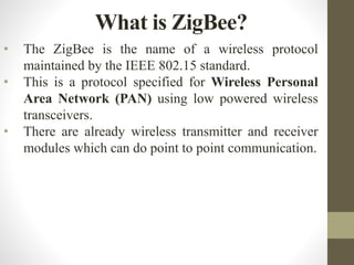

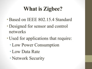
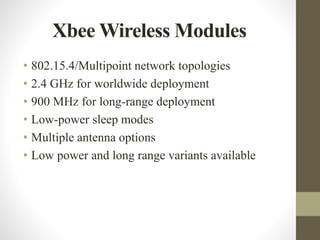
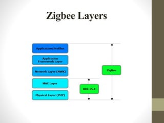
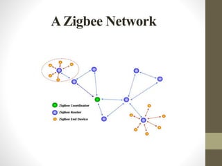
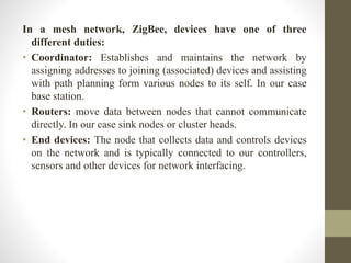
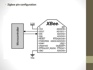
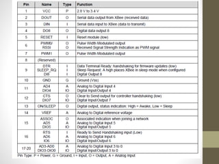


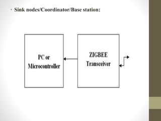
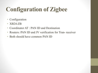
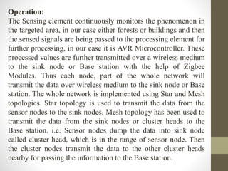
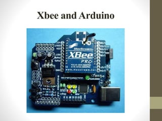
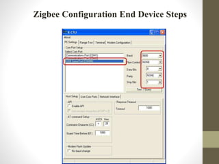
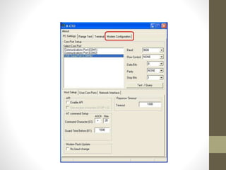
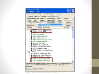
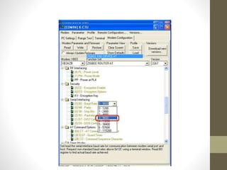
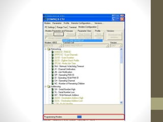
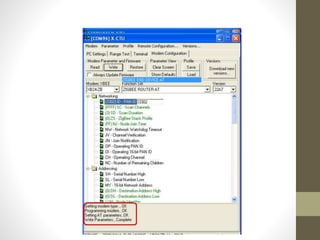
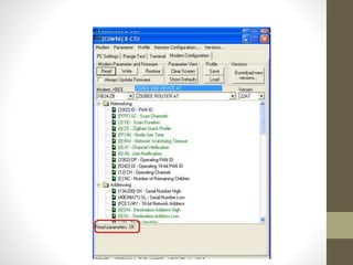
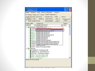
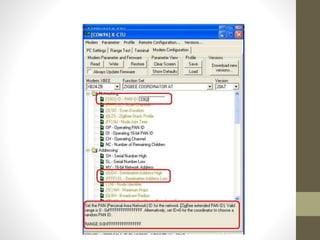
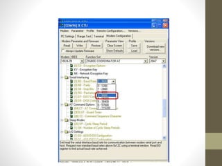


The document outlines the Zigbee wireless protocol and XBee modules, detailing their roles in establishing and maintaining wireless personal area networks (PAN). It explains the functionalities of Zigbee devices, including coordinators, routers, and end devices, and their configuration for various applications. Additionally, it describes the pin configurations and operation methods for the XBee modules used alongside microcontrollers like Arduino for tasks such as temperature monitoring and home automation.


![Zigbee technology [autosaved]](https://cdn.slidesharecdn.com/ss_thumbnails/zigbeetechnologyautosaved-140716030459-phpapp02-thumbnail.jpg?width=640&height=640&fit=bounds)


