WIRELESS COMMUNICATION , MOBILE COMPUTING Group Assignment
1.
UNITY UNIVERSITY
DEPARTMENT OFCOMPUTER SCIENCE
WIRELESS COMMUNICATION AND MOBILE
COMPUTING
GROUP ASSIGNMENT
Name ID
• Bezawit Abere………….UU86933R
• Eyakem Assefa ………..UU91443R
• Elias abebaw …………..UU89048R
• Estifanos Kidane……….UU87366R
• Fanuel Samuel…………UU87299R
2.
WIRELESS MODULATION TECHNIQUES
1.1.CONCEPTS OF MODULATION
1.2. WIRELESS MODULATION TECHNIQUES
1.3. AIR INTERFACE
1.4. PATH LOSS MODELS
1.5. MULTIPLE ACCESS TECHNIQUES
1.6. ORTHOGONAL FREQUENCY DIVISION MULTIPLEXING
1.7. ULTRA WIDE BAND RADIO TECHNIQUES
1.8. DIVERSITY TECHNIQUES
1.9. GSM HARDWARE
3.
1.1. CONCEPTS OFMODULATION
• Modulation converts the message signal frequency to one that is suitable for
transmission.
• It is formally defined as the process by which some characteristic of a carrier
wave is varied in accordance with an information-bearing signal.
• The information-bearing signal is referred to as the modulating signal.
• The output of the modulation process is called the modulated signal.
• Modulation is used to send information-bearing signals over long distances.
• The device that performs the modulation process in the transmitter is called a
modulator.
4.
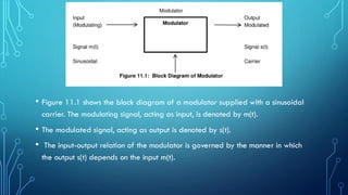
• Figure 11.1shows the block diagram of a modulator supplied with a sinusoidal
carrier. The modulating signal, acting as input, is denoted by m(t).
• The modulated signal, acting as output is denoted by s(t).
• The input-output relation of the modulator is governed by the manner in which
the output s(t) depends on the input m(t).
5.
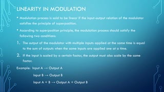
LINEARITY IN MODULATION
•Modulation process is said to be linear if the input-output relation of the modulator
satisfies the principle of superposition.
• According to superposition principle, the modulation process should satisfy the
following two conditions:
1. The output of the modulator with multiple inputs applied at the same time is equal
to the sum of outputs when the same inputs are applied one at a time.
2. If the input is scaled by a certain factor, the output must also scale by the same
factor.
Example: Input A → Output A
Input B → Output B
Input A + B → Output A + Output B
6.
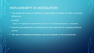
NON-LINEARITY IN MODULATION
•The modulation process is nonlinear if superposition principles are fully or partially
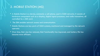
dishonored.
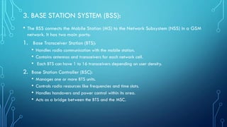
Example:
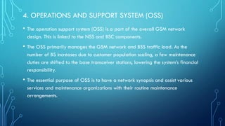
Input A + B might give an output that is not just A + B – it could be distorted or unexpected.
• Linearity and nonlinearity in modulation are very important for designing efficient
systems.
• The type of modulation techniques used also depends on this characteristic.
7.
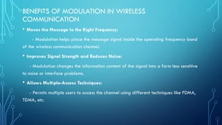
BENEFITS OF MODULATIONIN WIRELESS
COMMUNICATION
• Moves the Message to the Right Frequency:
- Modulation helps place the message signal inside the operating frequency band
of the wireless communication channel.
• Improves Signal Strength and Reduces Noise:
- Modulation changes the information content of the signal into a form less sensitive
to noise or interface problems.
• Allows Multiple-Access Techniques:
- Permits multiple users to access the channel using different techniques like FDMA,
TDMA, etc.
8.
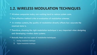
1.2. WIRELESS MODULATIONTECHNIQUES
• Wireless companies today are working hard to reduce system costs.
• One effective method is the re-evaluation of modulation schemes.
• In wireless systems, the quality of modulation directly affects how accurate the
received data is.
• Therefore, choosing the right modulation technique is very important when designing
and developing wireless data systems.
• Basically there are two types of modulation techniques:
1. Analog modulation technique
2. Digital modulation technique
9.
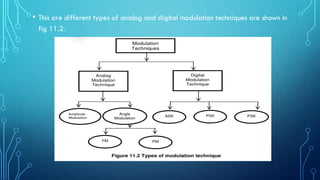
• This aredifferent types of analog and digital modulation techniques are shown in
fig 11.2.
10.
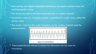
• Both analogand digital modulation techniques are used to convert data into
electromagnetic waves.
• This conversion allows the data to be sent over a wireless channel.
• Modulation works by changing specific properties of a radio wave, called the
carrier wave.
• The carrier wave has the same frequency as the wireless channel used for
communication.
• These properties are altered to embed the information into the wave for
transmission.
11.
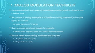
1. ANALOG MODULATIONTECHNIQUE
• Analog modulation is the process of transmitting an analog signal by placing it onto
a carrier wave.
• The purpose of analog modulation is to transfer an analog baseband (or low-pass)
signal, for example:
An audio signal, or A TV signal,
• Over an analog band-pass channel, for example:
A limited radio frequency band, or A cable TV network channel.
• We can further divide analog modulation into two parts:
1.1 Amplitude Modulation (AM)
1.2 Angle Modulation (AM)
12.
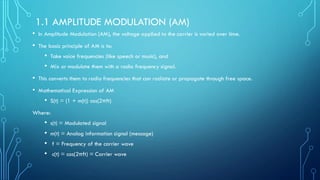
1.1 AMPLITUDE MODULATION(AM)
• In Amplitude Modulation (AM), the voltage applied to the carrier is varied over time.
• The basic principle of AM is to:
• Take voice frequencies (like speech or music), and
• Mix or modulate them with a radio frequency signal.
• This converts them to radio frequencies that can radiate or propagate through free space.
• Mathematical Expression of AM
• S(t) = (1 + m(t)) cos(2πft)
Where:
• s(t) = Modulated signal
• m(t) = Analog information signal (message)
• f = Frequency of the carrier wave
• c(t) = cos(2πft) = Carrier wave
13.
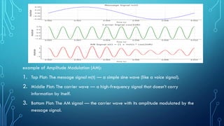
example of AmplitudeModulation (AM):
1. Top Plot: The message signal m(t) — a simple sine wave (like a voice signal).
2. Middle Plot: The carrier wave — a high-frequency signal that doesn’t carry
information by itself.
3. Bottom Plot: The AM signal — the carrier wave with its amplitude modulated by the
message signal.
14.
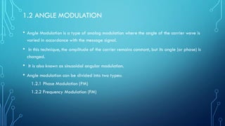
1.2 ANGLE MODULATION
•Angle Modulation is a type of analog modulation where the angle of the carrier wave is
varied in accordance with the message signal.
• In this technique, the amplitude of the carrier remains constant, but its angle (or phase) is
changed.
• It is also known as sinusoidal angular modulation.
• Angle modulation can be divided into two types:
1.2.1 Phase Modulation (PM)
1.2.2 Frequency Modulation (FM)
15.
1.2.1 PHASE MODULATION(PM)
• Phase Modulation (PM) is a form of angle modulation.
• It is a type of electronic modulation in which the phase of a carrier wave is varied to
transmit information.
• PM represents the information as variations in the instantaneous phase of the carrier
wave.
• PM is not very widely used, because:
• It requires more complex receiving hardware, and
• There can be ambiguity problems when trying to determine the exact phase
changes.
16.
1.2.2 FREQUENCY MODULATION
•Frequency Modulation (FM) is a form of angle modulation. In FM, the frequency of the
carrier waveform is varied in small but meaningful amounts.
• The change in frequency at any moment depends on another signal that changes over
time.
• The principal application of FM is in radio broadcasting.
• FM offers increased noise immunity, meaning it is less affected by interference.
• FM has less distortion compared to AM transmissions. And FM requires a much greater
bandwidth than AM.
17.
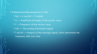
• Mathematical Representationof FM:
• S(t) = A (cos2πf + ∫1m(t)dt)
• A → Amplitude (strength) of the carrier wave.
• f → Frequency of the carrier wave.
• m(t) → The analog information signal.
• ∫ m(t) dt → Integral of the message signal, which determines the
frequency shift over time.
18.
2. DIGITAL MODULATIONTECHNIQUE
• Digital modulation is the process of converting an information-bearing discrete-time symbol
sequence into a continuous-time waveform.
• The purpose of digital modulation is to transfer a digital bit stream over an analog bandpass
channel (e.g., public telephone networks or radio frequency bands).
• If the modulating signal can only change its amplitude between a finite number of values and
changes occur only at discrete moments in time, it is called a digital signal.
• When this happens, the modulation is referred to as digital modulation.
• This are Types of Digital Modulation:
2.1 Amplitude-Shift Keying (ASK)
2.2 Frequency-Shift Keying (FSK)
2.3 Phase-Shift Keying (PSK)
19.
2.1 AMPLITUDE-SHIFT KEYING(ASK)
• ASK (Amplitude-Shift Keying) is a method of modulation. In ASK, we change the
amplitude (height) of the carrier wave based on the data. Everything else stays the same,
including the frequency of the wave.
• If we want to send bit 1, we use a carrier wave with a certain amplitude.
• If we want to send bit 0, we change the amplitude but keep the frequency unchanged.
• OOK (On-Off Keying) is a special version of ASK.
• In OOK, one amplitude is zero (meaning no signal is sent).
• When sending bit 0, we turn off the carrier wave (no signal = OFF).
• When sending bit 1, we turn on the carrier wave (signal present = ON).
• This creates an ON/OFF switching effect in the signal.
20.
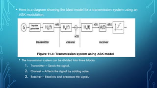
• Here isa diagram showing the ideal model for a transmission system using an
ASK modulation.
• The transmission system can be divided into three blocks:
1. Transmitter – Sends the signal.
2. Channel – Affects the signal by adding noise.
3. Receiver – Receives and processes the signal.
21.
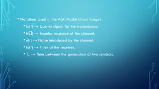
• Notations Usedin the ASK Model (From Image):
• hₜ(f) → Carrier signal for the transmission.
• h꜀
(f) → Impulse response of the channel.
• n(t) → Noise introduced by the channel.
• hᵣ(f) → Filter at the receiver.
• Tₛ → Time between the generation of two symbols.
22.
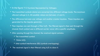
• In thefigure 11.4 Symbols Represented by Voltages:
• The transmitted symbols (data) are converted into different voltage levels. The maximum
allowed voltage is A. All possible values are between -A and A.
• The difference between one voltage and another creates impulses. These impulses are
generated by the impulse generator.
• Then impulses are sent through a filter hₜ(f). The filtered signal is then sent through the
channel. Each symbol uses a different carrier wave with a specific amplitude.
• After passing through the channel, the received signal contains:
• The transmitted symbol.
• Noise (n(t)).
• Inter-symbol interference (ISI) (symbols overlapping).
• The received signal is then filtered using hᵣ(f) to clean it.
23.
2.2 FREQUENCY-SHIFT KEYING(FSK)
• Frequency-shift keying (FSK) is a frequency modulation scheme. It transmits digital
information through discrete frequency changes of a carrier wave.
• The simplest FSK is binary FSK (BFSK). BFSK uses a couple of discrete frequencies to
transmit binary (0s and 1s) information.
• In this scheme, the “1” is called the mark frequency.
• The “0” is called the space frequency.
24.
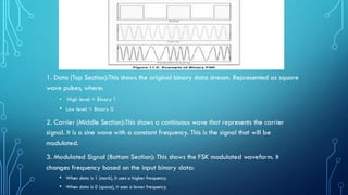
1. Data (TopSection):This shows the original binary data stream. Represented as square
wave pulses, where:
• High level = Binary 1
• Low level = Binary 0
2. Carrier (Middle Section):This shows a continuous wave that represents the carrier
signal. It is a sine wave with a constant frequency. This is the signal that will be
modulated.
3. Modulated Signal (Bottom Section): This shows the FSK modulated waveform. It
changes frequency based on the input binary data:
• When data is 1 (mark), it uses a higher frequency.
• When data is 0 (space), it uses a lower frequency.
25.
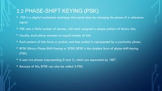
2.3 PHASE-SHIFT KEYING(PSK)
• PSK is a digital modulation technique that sends data by changing the phase of a reference
signal.
• PSK uses a finite number of phases, with each assigned a unique pattern of binary bits.
• Usually, each phase encodes an equal number of bits.
• Each pattern of bits forms a symbol, and that symbol is represented by a particular phase.
• BPSK (Binary Phase-Shift Keying or 2PSK) BPSK is the simplest form of phase-shift keying
(PSK).
• It uses two phases (representing 0 and 1), which are separated by 180°.
• Because of this, BPSK can also be called 2-PSK.
26.
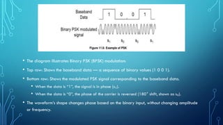
• The diagramillustrates Binary PSK (BPSK) modulation:
• Top row: Shows the baseband data — a sequence of binary values (1 0 0 1).
• Bottom row: Shows the modulated PSK signal corresponding to the baseband data.
• When the data is “1”, the signal is in phase (s₁).
• When the data is “0”, the phase of the carrier is reversed (180° shift, shown as s₀).
• The waveform’s shape changes phase based on the binary input, without changing amplitude
or frequency.
27.
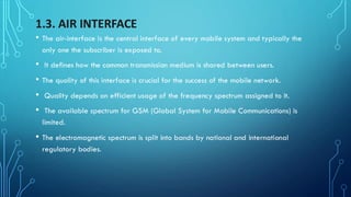
1.3. AIR INTERFACE
•The air-interface is the central interface of every mobile system and typically the
only one the subscriber is exposed to.
• It defines how the common transmission medium is shared between users.
• The quality of this interface is crucial for the success of the mobile network.
• Quality depends on efficient usage of the frequency spectrum assigned to it.
• The available spectrum for GSM (Global System for Mobile Communications) is
limited.
• The electromagnetic spectrum is split into bands by national and international
regulatory bodies.
28.
• For GSM,the 900 MHz and 1800 MHz bands are internationally recognized.
• These bands help achieve large economies of scale, reduce handset prices,
and allow GSM to flourish.
• A key requirement is that the MS (Mobile Station) and the network must
transmit and receive using the same reference clock.
• In a PLMN (Public Land Mobile Network), the MS connects to the fixed part of
the GSM system via a wireless channel.
• This wireless communication follows regulations and standards, forming the Air
Interface, also called the Um interface.
29.
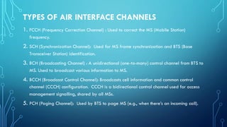
TYPES OF AIRINTERFACE CHANNELS
1. FCCH (Frequency Correction Channel) : Used to correct the MS (Mobile Station)
frequency.
2. SCH (Synchronization Channel): Used for MS frame synchronization and BTS (Base
Transceiver Station) identification.
3. BCH (Broadcasting Channel) : A unidirectional (one-to-many) control channel from BTS to
MS. Used to broadcast various information to MS.
4. BCCH (Broadcast Control Channel): Broadcasts cell information and common control
channel (CCCH) configuration. CCCH is a bidirectional control channel used for access
management signalling, shared by all MSs.
5. PCH (Paging Channel): Used by BTS to page MS (e.g., when there’s an incoming call).
30.
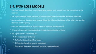
1.4. PATH LOSSMODELS
• Path loss models show how much signal gets weaker as it travels from the transmitter to the
receiver.
• The signal strength drops because of distance and other factors like terrain or obstacles.
• Some models are detailed and include things like hills and buildings, while others just use the
distance and frequency.
• Path loss means the loss of signal power as it moves through the air.
• It is very important when designing wireless communication systems.
• The signal can be weakened by:
• Free space (just distance)
• Reflection (bouncing off surfaces)
• Diffraction (bending around obstacles)
• Scattering (breaking into small parts by rough surfaces)
32.
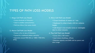
TYPES OF PATHLOSS MODELS
3. Micro Cell Path Loss Model
• Covers hundreds of meters to 1 km.
• Deployed in urban streets with low antenna
height.
• Cell shape is non-circular (cross or rectangle)
due to urban canyons.
4. Pico Cell Path Loss Model
• Covers 30 to 100 meters.
• Used indoors (buildings, offices).
• Enhances capacity and SINR with low power and
short range.
1. Mega Cell Path Loss Model
• Covers hundreds of kilometers.
• Used in satellite communications.
• Path loss follows free space model.
2. Macro Cell Path Loss Model
• Covers a few to tens of kilometers.
• Typical for traditional cellular networks.
• Operates around 900 MHz or 1800–1900 MHz
(PCS).
33.
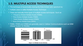
1.5. MULTIPLE ACCESSTECHNIQUES
• The technique of dynamically sharing the finite limited radio spectrum by
• multiple users is called Multiple Access Technique
• There are basically three types of multiple access techniques. Such as
• Frequency Division Multiple Access (FDMA)
• Time Division Multiple Access (TDMA)
• Code Division Multiple Access (CDMA)
• Space Division Multiple Access (SDMA)
• TDMA, FDMA and CDMA are generally used in Cellular Communications such as GSM
(Global System for Mobile).
34.
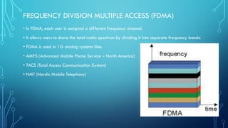
FREQUENCY DIVISION MULTIPLEACCESS (FDMA)
• In FDMA, each user is assigned a different frequency channel.
• It allows users to share the total radio spectrum by dividing it into separate frequency bands.
• FDMA is used in 1G analog systems like:
• AMPS (Advanced Mobile Phone Service – North America)
• TACS (Total Access Communication System)
• NMT (Nordic Mobile Telephony)
35.
FEATURES OF FDMA:
1.No precise time coordination is needed.
2. Suitable for narrowband analog systems.
3. Guard bands (spacing) are needed between channels — may cause wasted
bandwidth.
4. Continuous transmission requires duplexers, which can reduce battery life.
5. Needs high-performance filters in hardware.
6. Not affected by near-far problem, unlike CDMA.
36.
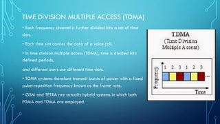
TIME DIVISION MULTIPLEACCESS (TDMA)
• Each frequency channel is further divided into a set of time
slots.
• Each time slot carries the data of a voice call.
• In time division multiple access (TDMA), time is divided into
defined periods,
and different users use different time slots.
• TDMA systems therefore transmit bursts of power with a fixed
pulse-repetition frequency known as the frame rate.
• GSM and TETRA are actually hybrid systems in which both
FDMA and TDMA are employed.
37.
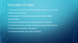
FEATURES OF TDMA
1.There can be only one carrier in the medium at any time, if a simple
TDMA scheme is followed.
2. Transmission is in bursts and hence is well suited for digital
communication.
3. Since the transmission is in bursts, Battery life is extended.
4. Transmission rate is very high compared to analog FDMA systems.
5. Precise synchronization is necessary.
6. Guard time between slots is also necessary.
38.
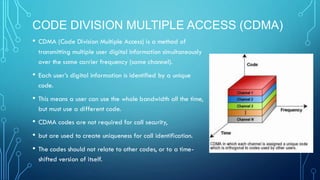
CODE DIVISION MULTIPLEACCESS (CDMA)
• CDMA (Code Division Multiple Access) is a method of
transmitting multiple user digital information simultaneously
over the same carrier frequency (same channel).
• Each user’s digital information is identified by a unique
code.
• This means a user can use the whole bandwidth all the time,
but must use a different code.
• CDMA codes are not required for call security,
• but are used to create uniqueness for call identification.
• The codes should not relate to other codes, or to a time-
shifted version of itself.
39.
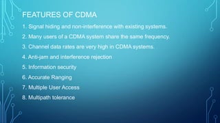
FEATURES OF CDMA
1.Signal hiding and non-interference with existing systems.
2. Many users of a CDMA system share the same frequency.
3. Channel data rates are very high in CDMA systems.
4. Anti-jam and interference rejection
5. Information security
6. Accurate Ranging
7. Multiple User Access
8. Multipath tolerance
40.
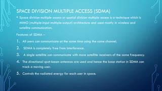
SPACE DIVISION MULTIPLEACCESS (SDMA)
• Space division multiple access or spatial division multiple access is a technique which is
MIMO (multiple-input multiple-output) architecture and used mostly in wireless and
satellite communication.
Features of SDMA –
1. All users can communicate at the same time using the same channel.
2. SDMA is completely free from interference.
3. A single satellite can communicate with more satellite receivers of the same frequency.
4. The directional spot-beam antennas are used and hence the base station in SDMA can
track a moving user.
5. Controls the radiated energy for each user in space.
41.
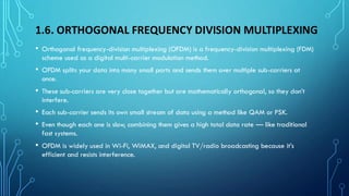
1.6. ORTHOGONAL FREQUENCYDIVISION MULTIPLEXING
• Orthogonal frequency-division multiplexing (OFDM) is a frequency-division multiplexing (FDM)
scheme used as a digital multi-carrier modulation method.
• OFDM splits your data into many small parts and sends them over multiple sub-carriers at
once.
• These sub-carriers are very close together but are mathematically orthogonal, so they don’t
interfere.
• Each sub-carrier sends its own small stream of data using a method like QAM or PSK.
• Even though each one is slow, combining them gives a high total data rate — like traditional
fast systems.
• OFDM is widely used in Wi-Fi, WiMAX, and digital TV/radio broadcasting because it’s
efficient and resists interference.
42.
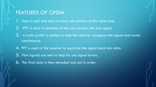
FEATURES OF OFDM
1.Data is split and sent on many sub-carriers at the same time.
2. IFFT is used to combine all the sub-carriers into one signal.
3. A cyclic prefix is added to help the receiver recognize the signal and avoid
interference.
4. FFT is used at the receiver to separate the signal back into data.
5. Pilot signals are sent to help fix any signal errors.
6. The final data is then decoded and put in order.
43.
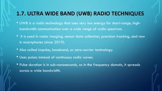
1.7. ULTRA WIDEBAND (UWB) RADIO TECHNIQUES
• UWB is a radio technology that uses very low energy for short-range, high-
bandwidth communication over a wide range of radio spectrum.
• It is used in radar imaging, sensor data collection, precision tracking, and now
in smartphones (since 2019).
• Also called impulse, baseband, or zero-carrier technology.
• Uses pulses instead of continuous radio waves.
• Pulse duration is in sub-nanoseconds, so in the frequency domain, it spreads
across a wide bandwidth.
44.
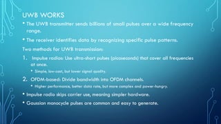
UWB WORKS
• TheUWB transmitter sends billions of small pulses over a wide frequency
range.
• The receiver identifies data by recognizing specific pulse patterns.
Two methods for UWB transmission:
1. Impulse radios: Use ultra-short pulses (picoseconds) that cover all frequencies
at once.
• Simple, low-cost, but lower signal quality.
2. OFDM-based: Divide bandwidth into OFDM channels.
• Higher performance, better data rate, but more complex and power-hungry.
• Impulse radio skips carrier use, meaning simpler hardware.
• Gaussian monocycle pulses are common and easy to generate.
45.
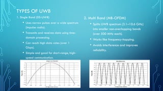
TYPES OF UWB
1.Single Band (DS-UWB)
• Uses narrow pulses over a wide spectrum
(impulse radio).
• Transmits and receives data using time-
domain processing.
• Can reach high data rates (over 1
Gbps).
• Simple and good for short-range, high-
speed communication.
2. Multi Band (MB-OFDM)
• Splits UWB spectrum (3.1–10.6 GHz)
into smaller non-overlapping bands
(over 500 MHz each).
• Works like frequency-hopping.
• Avoids interference and improves
reliability.
46.
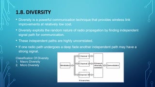
1.8. DIVERSITY
• Diversityis a powerful communication technique that provides wireless link
improvements at relatively low cost.
• Diversity exploits the random nature of radio propagation by finding independent
signal path for communication.
• These independent paths are highly uncorrelated.
• If one radio path undergoes a deep fade another independent path may have a
strong signal.
Classification Of Diversity
1. Macro Diversity
2. Micro Diversity
47.
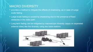
MACRO DIVERSITY
• providesa method to mitigate the effects of shadowing, as in case of Large
scale fading.
• Large scale fading is caused by shadowing due to the presence of fixed
obstacles in the radio path.
• Long term fading can be mitigated by macroscopic diversity (apply on separated
antenna sites) like the diversity using two base stations
48.
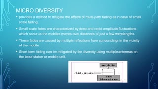
MICRO DIVERSITY
• providesa method to mitigate the effects of multi-path fading as in case of small
scale fading.
• Small scale fades are characterized by deep and rapid amplitude fluctuations
which occur as the mobiles moves over distances of just a few wavelengths.
• These fades are caused by multiple reflections from surroundings in the vicinity
of the mobile.
• Short term fading can be mitigated by the diversity using multiple antennas on
the base station or mobile unit.
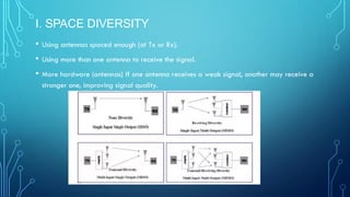
I. SPACE DIVERSITY
•Using antennas spaced enough (at Tx or Rx).
• Using more than one antenna to receive the signal.
• More hardware (antennas) If one antenna receives a weak signal, another may receive a
stronger one, improving signal quality.
51.
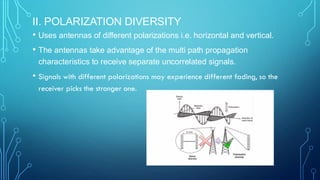
II. POLARIZATION DIVERSITY
•Uses antennas of different polarizations i.e. horizontal and vertical.
• The antennas take advantage of the multi path propagation
characteristics to receive separate uncorrelated signals.
• Signals with different polarizations may experience different fading, so the
receiver picks the stronger one.
52.
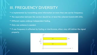
III. FREQUENCY DIVERSITY
•Is implemented by transmitting same information on more than one carrier frequency.
• The separation between the carriers should be at least the coherent bandwidth (Af)c.
• Different copies undergo independent fading.
• Only one antenna is needed.
• If one frequency is affected by fading or interference, others may still deliver the signal
properly.
53.
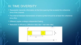
IV. TIME DIVERSITY
•Repeatedly transmits information at the time spacing that exceeds the coherence
time of the channel.
• The interval between transmission of same symbol should be at least the coherence
time (At)c.
• Different copies undergo independent fading.
• Reduction in efficiency (effective data rate < real data rate).
54.
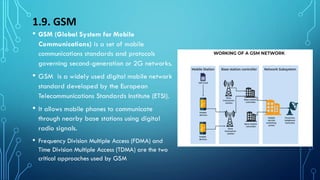
1.9. GSM
• GSM(Global System for Mobile
Communications) is a set of mobile
communications standards and protocols
governing second-generation or 2G networks.
• GSM is a widely used digital mobile network
standard developed by the European
Telecommunications Standards Institute (ETSI).
• It allows mobile phones to communicate
through nearby base stations using digital
radio signals.
• Frequency Division Multiple Access (FDMA) and
Time Division Multiple Access (TDMA) are the two
critical approaches used by GSM
55.
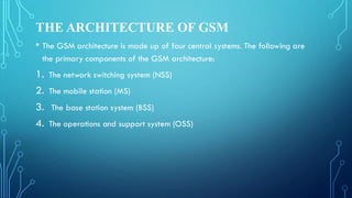
THE ARCHITECTURE OFGSM
• The GSM architecture is made up of four central systems. The following are
the primary components of the GSM architecture:
1. The network switching system (NSS)
2. The mobile station (MS)
3. The base station system (BSS)
4. The operations and support system (OSS)
56.
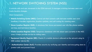
1. NETWORK SWITCHINGSYSTEM (NSS)
It controls calls and user movement in the GSM network. It manages switching between users and
tracks location changes.
Main Components:
• Mobile Switching Center (MSC): Central unit that connects calls between mobile users and
landlines. It handles registration, location updates, and call routing for roaming users.
• Home Location Register (HLR): A database that stores permanent user info like phone number,
services, and last known location.
• Visitor Location Register (VLR): Temporary database with info about users currently in the MSC
area. It helps provide service to visiting users.
• Equipment Identity Register (EIR): Checks if a mobile device is allowed on the network using its
IMEI number (device ID).
• Authentication Center (AuC): Provides security by verifying user identity and encrypting data to
protect calls and prevent fraud.
57.
2. MOBILE STATION(MS)
• A Mobile Station is a device, commonly a cell phone, used in GSM networks. It consists of
hardware components such as a display, digital signal processor, and radio transceiver, all
controlled by a SIM card.
• The SIM enables network access and communication.
• Mobile Stations are key parts of GSM systems, monitored and managed by the network
operator.
• Over time, their size has reduced, their functionality has improved, and battery life has
become more efficient.
58.
3. BASE STATIONSYSTEM (BSS):
• The BSS connects the Mobile Station (MS) to the Network Subsystem (NSS) in a GSM
network. It has two main parts:
1. Base Transceiver Station (BTS):
• Handles radio communication with the mobile station.
• Contains antennas and transceivers for each network cell.
• Each BTS can have 1 to 16 transceivers depending on user density.
2. Base Station Controller (BSC):
• Manages one or more BTS units.
• Controls radio resources like frequencies and time slots.
• Handles handovers and power control within its area.
• Acts as a bridge between the BTS and the MSC.
59.
4. OPERATIONS ANDSUPPORT SYSTEM (OSS)
• The operation support system (OSS) is a part of the overall GSM network
design. This is linked to the NSS and BSC components.
• The OSS primarily manages the GSM network and BSS traffic load. As the
number of BS increases due to customer population scaling, a few maintenance
duties are shifted to the base transceiver stations, lowering the system’s financial
responsibility.
• The essential purpose of OSS is to have a network synopsis and assist various
services and maintenance organizations with their routine maintenance
arrangements.
60.
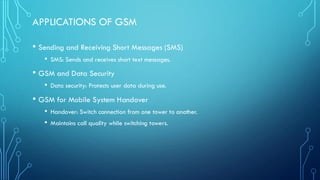
APPLICATIONS OF GSM
•Sending and Receiving Short Messages (SMS)
• SMS: Sends and receives short text messages.
• GSM and Data Security
• Data security: Protects user data during use.
• GSM for Mobile System Handover
• Handover: Switch connection from one tower to another.
• Maintains call quality while switching towers.


![谷歌留痕技术教程[ 𝙩𝙤𝙥 𝟮𝟯𝟯. 𝙘 𝙤𝙢 ]](https://cdn.slidesharecdn.com/ss_thumbnails/top233-260130173900-2eb784f9-thumbnail.jpg?width=640&height=640&fit=bounds)


