Downloaded 128 times

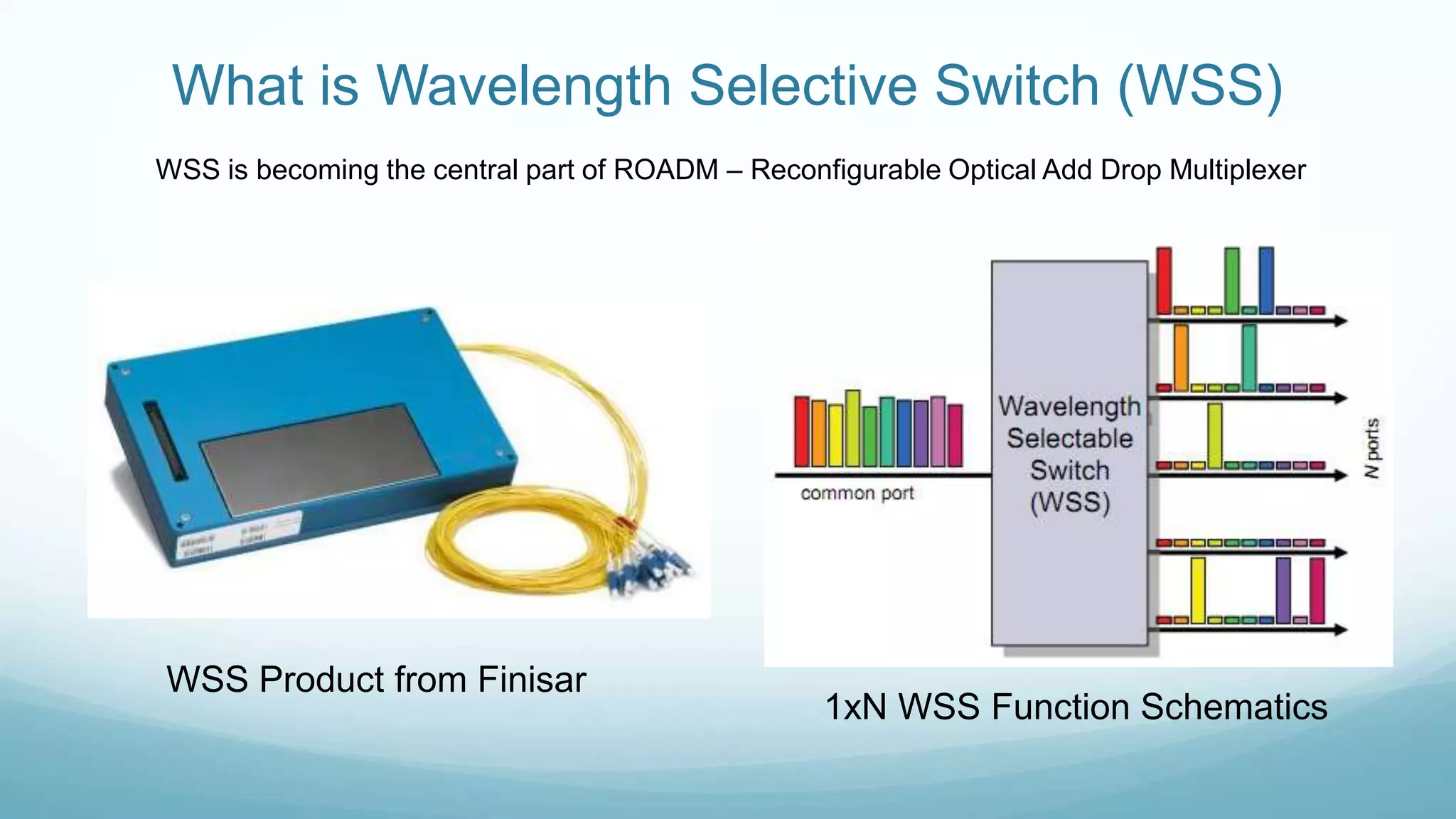
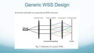
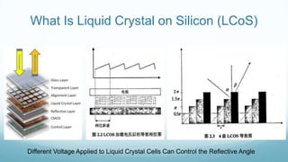
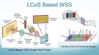


A wavelength selective switch (WSS) is a key component in reconfigurable optical add-drop multiplexers (ROADMs). The document discusses the design and function of a 1xN WSS from Finisar, detailing its operation using liquid crystal on silicon (LCOS) technology. It highlights the ability of LCOS-based WSS to control reflective angles through varying voltage on liquid crystal cells.