Downloaded 64 times


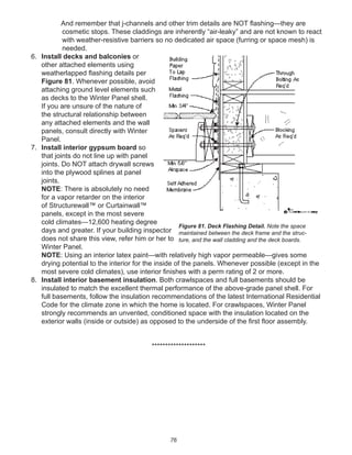
![88
example, the Home Ventilation Institute.3
b. Supply systems – systems that bring in outside air and so may slightly pressurize the
home. For example, see central fan integrated supply (CFIS) ventilation systems.4
NOTE: Slightly pressurizing a home is an acceptable practice in all but the coldest of
climates—9,000 heating degree days (HDD) or less (but also depending on interior
moisture regimes).
c. Exhaust systems – systems that rely exclusively on exhaust and so may slightly
depressurize the home.5
NOTE: Slightly de-pressurizing a home is an acceptable practice in all but hot humid
climates (ASHRAE-defined warm-humid climates).
3. Install a “climate center” control that includes a hygrometer or humidistat as well as a
thermostat. Or, supply the homeowner with a stand-alone hygrometer that provides feedback
on interior relative humidity conditions. Guidance should be given to homeowners to maintain
low to moderate wintertime humidity levels
4. Discourage homeowners from using ventless combustion appliances, such as
kerosene heaters. Independent of any combustion safety issues, these units dump significant
amounts of moisture into your home, whether you need/want it or not.
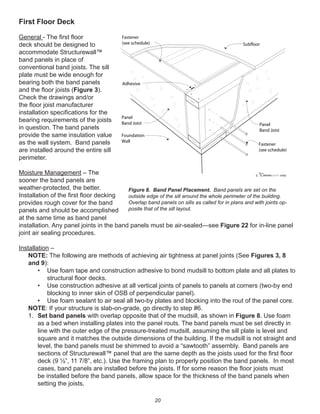
Managing “wet” rooms –
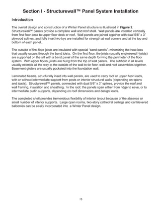
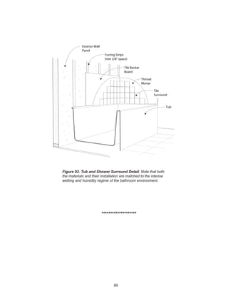
1. Install appropriate materials in tub and shower surrounds. See Figure 92. This includes
cementitious backerboard or non-paper faced gypsum board (NOT moisture-resistant
[MR] gypsum board) with a waterproof surface treatment and the tub or shower surround
weatherlapped with respect to the lip of the tub or shower basin.
2. Install a pan, with drain outlet, underneath all clothes washers particularly in locations
with living space below the clothes washer.
3. Install a single-throw shut-off on the clothes washer hot and cold supplies.
HVAC ducts in conditioned space –
For homes with central forced air systems, think of the air handler and ducts as the “lungs” for
the house. They need to be inside conditioned space—not in vented attics, vented crawlspaces,
garages. Keeping them inside conditioned space eliminates a whole host of indoor air quality and
building durability concerns.
3 http://www.hvi.org/.
4 http://www.fancycler.com/
5 For more information see the Home Ventilation Institute - http://www.hvi.org/.](https://image.slidesharecdn.com/wpcompleteguide-150807180150-lva1-app6892/85/Winter-Panel-Complete-Guide-88-320.jpg)


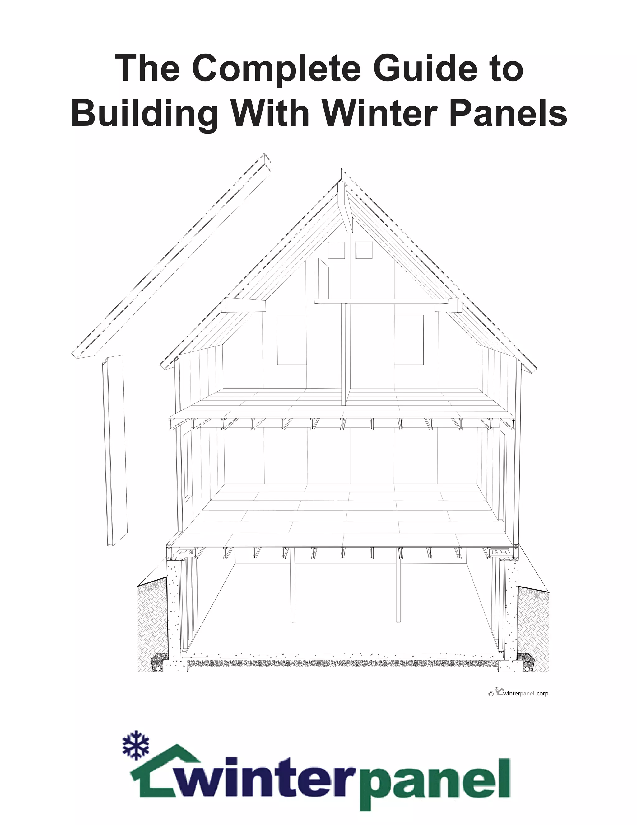
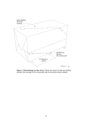
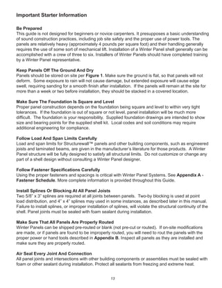
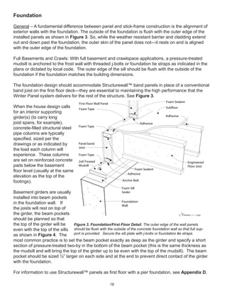
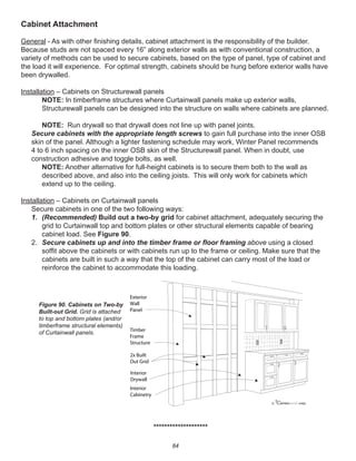
This document provides an overview and installation guide for Winter Panel structurewall panel systems. It discusses foundations, floor decks, wall panels, door and window openings, roof panels, and completing the building enclosure. The guide emphasizes proper moisture management techniques and provides numbered step-by-step installation sequences accompanied by detailed illustrations. It is intended for experienced builders and assumes a basic knowledge of construction practices.


