Color Coated Galvalume/Galvanized Sheet Manufacturers in Bangalore, Chennai, ...
Jack_Lambourne - Portfolio
1. CLIENT
PROJECT
JOB NUMBER
DATE
SCALE
DRAWN
CHECKED
STATUS FOR REVIEW
DRAWING
CHECKER
CAD FILE
CAD REF
BLOCK DRAWING NUMBER ZONE REVISION
NOTE
ALL DIMENSIONS TO BE CHECKED ON SITE
NO DIMENSIONS TO BE SCALED FROM THIS DRAWING
THIS DRAWING IS TO BE READ IN CONJUNCTION WITH
RELEVANT CONSULTANTS DRAWINGS
REV DATE DESCRIPTION CHKD DRN
COPYRIGHT (C)
Jack Lambourne
27/04/201521:09:21
27/04/2015 21:09:21
Final Presentation
05
Author
313
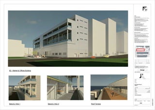
B2 - Market Place &
Offices
D.I.T
Design
N
NOTES
Exterior Wall Construction:
3mm Aluminium Rainscreen fixed via Steel Supports to Engineers
Specs
to 150mm PIR Insulation to NBS Spec. J21
with Breather Membrane fixed and taped to NBS Spec. M50
with Waterproofing Membrane taped and fixed to Warm Side of
Insulation
on 200mm Cast in situ Concrete Inner leaf shear wall
Ground Floor Construction:
25mm Solid Stone finish to NBS Spec. M40
on 30mm Stone Mortar to NBS Spec. Z21
on 75mm Screed to NBS Spec. Q23
on 200mm PIR Insulation to NBS Spec. J21
on 200mm Cast In situ Concrete Slab to NBS Spec. E10
Upper Floor Construction:
700 x 640mm Cast In situ Concrete Beam to NBS Spec. E05
supporting 225mm Hollowcore Slab to NBS Spec. E60
with 75mm Screed Cast on top to NBS Spec. Q23
with 195mm Raised Access Pedestals
with 20mm Raised Access Panel Finish to NBS Spec. M50
Balcony Floor Construction:
35mm Sandstone Ash Paving Slab (500 x 500mm) to NBS Spec.
Q10
on 30mm Layer of Stone Mortar to NBS Spec. Z21
on 75mm Screed Layed to a fall of 1:100 to NBS Spec. Q23
on 150mm PIR Insulation (0.023) to NBS Spec. J21
on 225mm Casr in Situ Concrete Balcony slab to NBS Spec. E10
Aco Drainage System in Balcony which Drains into Wall Cavity
Glazing System:
Double Glazed Thermally Broken Glazing System fixed with
Manufacturers Specs.
on Aluminium Cover Flashing to NBS Spec. H71
on Vapour Control Layer Taped and sealed at Glazing Frame
on 50mm PIR Insulation (0.023) to NBS Spec. J21
on 250 x 150mm Aerated Concrete Block to NBS Spec. E60
on Isokorb System preventing Cold Bridging
Balcony View 1 Balcony View 2 Roof Terrace
B2 - Market & Offices Building
2.
3.
4. Wall Construction
102.5mm Outer Leaf Brick Rainscreen with
100mm Cavity with Stainless Steel Cavity tray to aid with both structure
and drainage with
50mm PIR Rigid Insulation in cavity fixed to OSB with
Stainless steel wall ties every 600 c/c fixed to
12mm OSB with Breather membrane fixed to
100mm of Quilted Insulation (Rockwool) which has a
Vapour Control Layer keeping out moisture which is fixed behind
20mm Gypsum Plasterboard.
200
410
325
120
102
50
100
43
75
50
Roof Construction
400mm Concrete Slates on Roof fixed every 325mm C/C onto
50 x 35mm Timber Battens which are fixed onto
35mm OSB for addtional structural support with a
Breather membrane laid with appropriate tapes and seals to control roof
moisture installed with a timber tilting fillet fixed onto
50 x 50mm Timber Battens which are fixed onto a 200mm C16 Timber
Rafter.
50
100 x 50mm Timber Battens
fixed to underside of 200mm
C16Timber Rafter
150mm EPS Rigid Insulation installed below C16 Timber
rafter to maintain thermal continuity
Insulated Cavity Closer fixed above Brickwork and cavity insulation
200mm C16 Timber Rafter
100mm EPS Insulation installed inbetween
timber rafters with
additional 50mm EPS Insulation installed
above rafter
16mm SW Soffit Board fixed to
18mm SW Fascia Board which is then fixed to
a timber tilting fillet
100 x 50mm Timber Battens every 600 c/c
120mm PVC Gutter Piece fixed to
18mm SW Fascia Board with
aluminium flashing laid into Gutter with
Eaves ventilater fixed onto the top of the fascia piece
Allowing ventilation under the slates
Jack Lambourne
C12700655
Building Performance Assignment
Detail C
03
1 : 5
Detail C
Key Section
5. Wall Construction
Ventilated Facade System with 18mm Cedar Rotating
Panels fixed to
a continuous breather membrane/wind barrier to maintain air
tightness which is fixed to
12mm OSB on the outer leaf with
100mm EPS Rigid Insulation (0.023) with an additional
70mm EPS Rigid Insulation supported by 70 x 35mm Timber
Battens every 400 c/c fixed to
18mm OSB fixed to a vapour control layer which maintains
airtightness. This is fixed to a
25mm Service Cavity with 25 x 25mm Timber Battens with a
20mm Gypsum Plasterboard Finish
25
208
Roof Construction
400mm Concrete Slates on Roof fixed
every 325mm C/C onto
50 x 35mm Timber Battens which are fixed
onto
35mm OSB for addtional structural support
with a
Breather membrane laid with appropriate
tapes and seals to control roof moisture
installed on
200mm EPS Rigid Insulation supported by
200mm x 50mm Timber Engineered Joists
fixed onto
A Vapour Control membrane which
maintains air tightness stuck to two Layers
of 12.5mm Gypsum Plaster
Flat Roof Construction
Bitumen Roofing Felt torched on as a finish and lapped up 150mm over upstand piece on
Breather Membrane which is laid and sealed with appropriate agents on
150mm PIR Rigid insulation which combines with wall insulation to keep thermal envelope which is laid onto
A vapour control layered membrane wrapped around onto the wall onto
20mm OSB fixed onto
175 x 45mm C16 Timber battens on
20mm Gypsum Plasterboard
200mm x 22.5mm RSJ sized to engineers specs.
supporting load of ventilated facade and timber flat roof
fixed to 100 x 35mm Timber Batten all supported on a
200 x 200mm Steel Column to engineers specs.
1517520149
10569
206
The bottom connection of the ventilated facade allows airflow through facade
Jack Lambourne
C12700655
Building Performance Assignment
Detail E
051 : 5
Detail E
Key Section
6. 6 7
Interior Exterior
700 x 640mm Cast In situ Concrete
Beam to NBS Spec. E05
supporting 225mm Hollowcore Slab
to NBS Spec. E60
with 75mm Screed Cast on top to
NBS Spec. Q23
with 195mm Raised Access
Pedestals
with 20mm Raised Access Panel
Finish to NBS Spec. M50
35mm Sandstone Ash Paving Slab (500 x 500mm) to NBS
Spec. Q10
on 30mm Layer of Stone Mortar to NBS Spec. Z21
on 75mm Screed Layed to a fall of 1:100 to NBS Spec. Q23
on 150mm PIR Insulation (0.023) to NBS Spec. J21
on 225mm Casr in Situ Concrete Balcony slab to NBS Spec.
E10
Aco Drainage System in Balcony which Drains into Wall
Cavity
U-Value: 0.124 W/m2K
Double Glazed Thermally Broken Glazing System fixed with
Manufacturers Specs. (U-Value: 1.35 W/m2K)
on Aluminium Cover Flashing to NBS Spec. H71
on Vapour Control Layer Taped and sealed at Glazing Frame
on 50mm PIR Insulation (0.023) to NBS Spec. J21
on 250 x 150mm Aerated Concrete Block to NBS Spec. E60
on Isokorb System preventing Cold Bridging
Double Glazed Thermally Broken Glazing System fixed
with Manufacturers Specs.(U-Value: 1.35 W/m2K)
on Vapour Control Layer taped and wrapped to NBS
Spec. J40
on Two Thermal Blocks to NBS Spec. E60
on Cast concrete to NBS Spec. E10
with 100mm PIR Insulation (0.023) screwed through to
concrete, refer to engineers specs
with Breather membrane layer to NBS Spec. J40
with Rigid Cement Material
with Glass Spandrel Panel Finish to Manufacturers
Specs.
U-Value: 0.177 W/m2K
Double Glazed Thermally Broken Glazing
System fixed with Manufacturers Specs.(U-
Value: 1.35 W/m2K)
on Aluminium Cover Flashing to NBS Spec.
H71
on Vapour Control Layer Taped and sealed at
Glazing Frame
on 50mm PIR Insulation (0.023) to NBS Spec.
J21
on 250 x 150mm Aerated Concrete Block to
NBS Spec. E60
on Isokorb System preventing Cold Bridging
200mm Cast In situ Concrete Parapet
Piece to NBS E10
with Rubber Gasket Frame to NBS
M50
with 20mm Glass Parapet Finish to
Manufacturers Specs
fixed via engineers specs
35mm Precast Parapet Capping Piece to
NBS Spec. F31
with Specialised Gasket Piece fixed to the
top of the glass parapet.
Finished with Aluminium Flashing Piece
Fixed via Engineers Specs
700 x 640mm Cast In situ Concrete Beam to NBS
Spec. E05
supporting 225mm Hollowcore Slab to NBS Spec.
E60
with 75mm Screed Cast on top to NBS Spec. Q23
with 195mm Raised Access Pedestals
with 20mm Raised Access Panel Finish to NBS
Spec. M50
3mm Aluminium Rainscreen fixed via Steel Supports to
Engineers Specs
to 100mm PIR Insulation to NBS Spec. J21
with Breather Membrane fixed and taped to NBS Spec.
M50
with Waterproofing Membrane taped and fixed to Warm
Side of Insulation
U-Value: 0.19 W/m2K
Aluminium Sill Profile fixed back to Cast
in Situ Parapet Piece
with Special Mastic to Separate
Materials
3mm Aluminium Rainscreen fixed via
Steel Supports to Engineers Specs
to 150mm PIR Insulation to NBS Spec.
J21
with Breather Membrane fixed and
taped to NBS Spec. M50
with Waterproofing Membrane taped
and fixed to Warm Side of Insulation
U-Value: 0.129 W/m2K
200mm Cast In situ Concrete
Parapet Piece to NBS E10
with Rubber Gasket Frame to NBS
M50
with 20mm Glass Parapet Finish to
Manufacturers Specs
fixed via engineers specs
400 x 400mm Cast In situ Concrete
Column designed
to Engineers Specs
Aluminium Sill Profile fixed back
to Cast in Situ Parapet Piece
with Special Mastic to Separate
Materials
3mm Aluminium Rainscreen
fixed via Steel Supports to
Engineers Specs
to 150mm PIR Insulation to NBS
Spec. J21
with Breather Membrane fixed
and taped to NBS Spec. M50
with Waterproofing Membrane
taped and fixed to Warm Side of
Insulation
U-Value: 0.129 W/m2K
First FFL
9.365
Second FFL
13.325
Third FFL
17.285
39603960
274512152745
6513
3000
3
Double Glazed Thermally Broken
Glazing System fixed with
Manufacturers Specs.(U-Value: 1.35
W/m2K)
with Glass Spandrel Panel Finish to
Manufacturers Specs.
First FFL
9.365
Second FFL
13.325
Third FFL
17.285
1000
1000
1000
3
6
7
400 X 400mm Cast In
Situ Concrete Column
wrapped in Insulation
to NBS Spec. J21
to avoid Thermal
Bridge
35mm Sandstone Ash Paving Slab (500 x 500mm) to
NBS Spec. Q10
on 30mm Layer of Stone Mortar to NBS Spec. Z21
on 75mm Screed Layed to a fall of 1:100 to NBS
Spec. Q23
on 150mm PIR Insulation (0.023) to NBS Spec. J21
on 225mm Casr in Situ Concrete Balcony slab to
NBS Spec. E10
Aco Drainage System in Balcony which Drains into
Wall Cavity
U-Value: 0.124 W/m2K
200mm Cast In situ Concrete Parapet Piece to NBS E10
with Rubber Gasket Frame to NBS M50
with 20mm Glass Parapet Finish to Manufacturers Specs
fixed via engineers specs
35mm Precast Parapet Capping Piece to
NBS Spec. F31
with Specialised Gasket Piece fixed to the
top of the glass parapet.
Finished with Aluminium Flashing Piece
Fixed via Engineers Specs
Exterior
Interior
500
500
3000
50
956 151
400 X 400mm Cast In
Situ Concrete Column
wrapped in Insulation
to NBS Spec. J21
to avoid Thermal
Bridge
35mm Sandstone Ash Paving Slab (500 x 500mm) to
NBS Spec. Q10
on 30mm Layer of Stone Mortar to NBS Spec. Z21
on 75mm Screed Layed to a fall of 1:100 to NBS Spec.
Q23
on 150mm PIR Insulation (0.023) to NBS Spec. J21
on 225mm Casr in Situ Concrete Balcony slab to NBS
Spec. E10
Aco Drainage System in Balcony which Drains into Wall
Cavity
U-Value: 0.124 W/m2K
200mm Cast In situ
Concrete Parapet Piece to
NBS E10
with Rubber Gasket Frame
to NBS M50
with 20mm Glass Parapet
Finish to Manufacturers
Specs
fixed via engineers specs
35mm Precast Parapet Capping Piece to
NBS Spec. F31
with Specialised Gasket Piece fixed to the
top of the glass parapet.
Finished with Aluminium Flashing Piece
Fixed via Engineers Specs
Aluminium Sill Profile fixed back
to Cast in Situ Parapet Piece
with Special Mastic to Separate
Materials
3mm Aluminium Rainscreen
fixed via Steel Supports to
Engineers Specs
to 150mm PIR Insulation to NBS
Spec. J21
with Breather Membrane fixed
and taped to NBS Spec. M50
with Waterproofing Membrane
taped and fixed to Warm Side of
Insulation
U-Value: 0.129 W/m2K
Double Glazed Thermally Broken Glazing System fixed with
Manufacturers Specs.(U-Value: 1.35 W/m2K)
on Aluminium Cover Flashing to NBS Spec. H71
on Vapour Control Layer Taped and sealed at Glazing Frame
on 50mm PIR Insulation (0.023) to NBS Spec. J21
on 250 x 150mm Aerated Concrete Block to NBS Spec. E60
on Isokorb System preventing Cold Bridging
CLIENT
PROJECT
JOBNUMBER
DATE
SCALE
DRAWN
CHECKED
STATUSFORREVIEW
DRAWING
CHECKER
CADFILE
CADREF
BLOCKDRAWINGNUMBERZONEREVISION
NOTE
ALLDIMENSIONSTOBECHECKEDONSITE
NODIMENSIONSTOBESCALEDFROMTHISDRAWING
THISDRAWINGISTOBEREADINCONJUNCTIONWITH
RELEVANTCONSULTANTSDRAWINGS
REVDATEDESCRIPTIONCHKDDRN
COPYRIGHT(C)
JackLambourne
27/04/201523:35:37
27/04/201523:35:37
1:20
Section
CC/Elevation/Plan
05
JackLambourne
334
B2-MarketPlace&Offices
D.I.T
Design
1 : 20
Section CC
1 : 20
Part Elevation
1 : 20
02 First FFL Part Plan3D
Key Plan NTSKey Section NTS
N
7. 7
200mm Cast In situ Concrete Parapet Piece to NBS E10
with Rubber Gasket Frame to NBS M50
with 20mm Glass Parapet Finish to Manufacturers Specs
fixed via engineers specs
35mm Precast Parapet Capping Piece to NBS Spec. F31
with Specialised Gasket Piece fixed to the top of the glass
parapet.
Finished with Aluminium Flashing Piece Fixed via Engineers
Specs
Aluminium Sill Profile fixed back to Cast in Situ Parapet
Piece
with Special Mastic to Separate Materials
3mm Aluminium Rainscreen fixed via Steel Supports to
Engineers Specs
to 150mm PIR Insulation to NBS Spec. J21
with Breather Membrane fixed and taped to NBS Spec. M50
with Waterproofing Membrane taped and fixed to Warm
Side of Insulation
U-Value: 0.129 W/m2K
35mm Sandstone Ash Paving Slab (500 x 500mm) to NBS Spec.
Q10
on 30mm Layer of Stone Mortar to NBS Spec. Z21
on 75mm Screed Layed to a fall of 1:100 to NBS Spec. Q23
on 150mm PIR Insulation (0.023) to NBS Spec. J21
on 225mm Casr in Situ Concrete Balcony slab to NBS Spec.
E10
Aco Drainage System in Balcony which Drains into Wall Cavity
U-Value: 0.124 W/m2K
CLIENT
PROJECT
JOB NUMBER
DATE
SCALE
DRAWN
CHECKED
STATUS FOR REVIEW
DRAWING
CHECKER
CAD FILE
CAD REF
BLOCK DRAWING NUMBER ZONE REVISION
NOTE
ALL DIMENSIONS TO BE CHECKED ON SITE
NO DIMENSIONS TO BE SCALED FROM THIS DRAWING
THIS DRAWING IS TO BE READ IN CONJUNCTION WITH
RELEVANT CONSULTANTS DRAWINGS
REV DATE DESCRIPTION CHKD DRN
COPYRIGHT (C)
Jack Lambourne
27/04/201521:14:13
27/04/2015 21:14:13
1 : 5
Parapet
Detail
05
Jack Lambourne
336
B2 - Market Place &
Offices
D.I.T
Design
Parapet 3D
1 : 5
Parapet Detail
Parapet 3D Step 1 Parapet 3D Step 2
Parapet 3D Step 3 Parapet 3D Step 4
Parapet 3D Step 5 Parapet 3D Step 6
Parapet Key 3D
Step 1
700 x 640mm Cast In situ Concrete Beam cast along with 225mm Cast in Situ
Balcony slab via steel rebar
and thermal block placed on top of balcony slab.
Step 2
200mm Concrete
Parapet Piece cast
into balcony slab on
top of thermal block.
150mm PIR
Insulation installed
on top of balcony
slab and fixed.
Step 3
75mm Screed poured to a fall of 1 100 with 30mm
of stone mortar spread on top of screed. Lead
flashing is then torched on the interior side of the
parapet piece.
150mm PIR Insulation is then fixed onto balcony
slab and beam on the exterior.
Step 4
35mm Stone paving is then layed on top of
stone mortar which is 500 x 500mm. Aluminium
Steel supports are then fixed via self drilling
screws, see enginners specs.
Step 5
3mm Aluminium Rainscreen installed onto steel
supports 500mm wide with 20mm gap for ventilation.
Aluminium sill profile then installed via engineers
specs.
Step 6
35mm Precast concrete parapet
capping piece fixed onto top of glass
and parapet piece with mastic
inbetween. Aluminium flashing piece
screws onto capping piece.
Parapet glass piece then installed with
steel frame and mastic. 20mm Glass
fixed via bolts by engineers specs.
Key Section
Material
Description
Shape/Size
Density
Weight
Strength
UV
Performance
Fire Rating
Thermal
Conductivity
R - Value
Permeablilty
Acoustic
Performance
Water Absorption
PIR Insulation Stone Paving Stone Mortar Screed Balcony Slab Glazing Thermal Block Concrete Beam Lead Flashing PVC-u Pipe Vapour Barrier Aluminium Rainscreen Breather Membrane Aluminium Flashing Aluminium Supports Parapet Glazing
Thermal Layer
2400 x 1200mm
30-60 kg/m3
N/A
Poor
UV can damage material
Class 1
0.023 w/mk
5.71
High Vapour Resistance
Low Moisture Absorption
Good
Finish Material
500 x 500mm
2,400Kg/m³
N/A
Good
UV cannot damage
material
Poor
1.7 w/mk
0.08
Low Vapour Resistance
High Moisture Absorption
Poor
Used as substrate
30mm Thick
1,620Kg/m³
2.162 gram per (cubic cm)
Fair
UV cannot damage
material
Poor
1.73 w/mk
0.20
Low Vapour Resistance
High Moisture Absorption
Poor
Used as substrate
75mm Thick
2,000Kg/m³
20 kg per m2
Fair
UV cannot damage
material
Poor
1.2 w/mk
0.06
Low Vapour Resistance
High Moisture Absorption
Poor
Used as substrate
225mm Thick
2,400Kg/m³
N/A
Excellent
Durable against UV
Good
0.5 w/mk
0.33
100 GNs/kg.m
Medium Moisture
Absorption
Good
Used as support
700 x 640mm
2,400Kg/m³
N/A
Excellent
Durable against UV
Good
0.5 w/mk
0.33
100 GNs/kg.m
Medium Moisture
Absorption
Good
Used as Rainscreen
3mm Thick
2,400Kg/m³
2.5kg/m2
Good
UV cannot damage
material
Poor
1.9 w/mk
0.61
Low Vapour Resistance
High Moisture Absorption
Fair
Used as Parapet Flashing
3mm Thick
2,400Kg/m³
2.5kg/m2
Good
UV cannot damage
material
Poor
1.9 w/mk
0.61
Low Vapour Resistance
High Moisture Absorption
Fair
Used as Supports for
Rainscreen
3mm Thick
2,400Kg/m³
2.5kg/m2
Good
UV cannot damage
material
Poor
1.9 w/mk
0.61
Low Vapour Resistance
High Moisture Absorption
Fair
Used as light source
6mm Thick Double
Glazed
2,500 kg/m3
10kg per m2
Good
Durable against UV
Class 1
0.8 w/mK
2.38
100 GNs/kg.m
Low Moisture Absorption
Good
Used as finish
20mm Thick Glass
2,500 kg/m3
10kg per m2
Good
Durable against UV
Class 1
0.8 w/mK
2.38
100 GNs/kg.m
Low Moisture
Absorption
Good
Used as drainage Pipe
50mm Diameter
1.38 g/cm3
N/A
Good
N/A
Good
0.16 w/mK
1.05
Medium Vapour
Resistance
Low Moisture Absorption
Fair
0.001
Used as moisture
protection layer
0.52mm thick x 2m Long
Low Density
N/A
Fair
N/A
Poor
0.16 w/mK
1100 MNs/g
0.03 mlv
Poor
0.001
Used as thermal break
250mm x 150mm
500Kg/m³
N/A
Excellent
UV cannot damage
material
Good
0.16 w/mK
1100 MNs/g
Good
Medium Moisture
Absorption
Used as weather
protection
1.32mm thick x 1.2m
2,400Kg/m³
14.92kg per m2
Poor
Durable against UV
Good
35.3 w/mk
0.5097
Medium Moisture
Absorption
Poor
Medium Vapour
Resistance
0.47
Used as air layer
0.25mm thick x 2m Long
Low Density
1200g/m2
Fair
N/A
Euroclass A2
0.0278 w/mK
1100 MNs/g
0.05 mlv
Poor
8. 5600
U n i t 1
U n i t 2
U n i t 3
S i t e N o t i c e
B u s D e p o t
Proposed Playground
S i t e N o t i c e
External Stairs & Lift 1
- Fire Protected
External Stairs & Lift 2 - Fire Protected
Proposed Park Landscape
Proposed External Landscape for
pedestrian use
Ramp gradient 1 12 & Stairs
Ramp gradient 1 12 to carpark
Proposed Building (to be designed at a
later Stage
Proposed Building
(to be designed at a
later Stage
AOV
AOV AOV
AOV
Apartments
/Concrete
Core 1
Apartments/
Concrete
Core 2
AOV
Fall
Fall
Fall Fall
Flat Roof
Flat Roof
21415
20270
19750
184706617
4552
6734
9384
ENTRANCE
B r o a d s t o n e
L u a s
K i n g ' s I n n P a r k
E x i s t i n g S u r r o u n d i n g B u i l d i n g s
E x i s t i n g B u i l d i n g s
T h e R o y a l S o c i e t y o f
t h e K i n g ' s I n n
20315
ESB
10453
14810
CLIENT
PROJECT
JOB NUMBER
DATE
SCALE
DRAWN
CHECKED
STATUS FOR REVIEW
DRAWING
CHECKER
CAD FILE
CAD REF
BLOCK DRAWING NUMBER ZONE REVISION
NOTE
ALL DIMENSIONS TO BE CHECKED ON SITE
NO DIMENSIONS TO BE SCALED FROM THIS DRAWING
THIS DRAWING IS TO BE READ IN CONJUNCTION WITH
RELEVANT CONSULTANTS DRAWINGS
COPYRIGHT (C)
Group 4
Key Site Plan
18/11/201517:07:43
18/11/2015 17:07:43
1 : 1000
01 - Site Location Map
T5
Author
0000
Regulatory Processes
Dublin City Council
PLANNING
1 : 1000
Site Location Plan
North
W a t e r m a i n s
S i t e b o u n d a r y
North
O . S M A P N O . - 3 2 6 3 - 9 0 4
S u r f a c e W a t e r
F o u l W a t e r
E l e c t r i c i t y
︵
E S B
︶
9. Stair Core
Basement Carpark
Glass Balcony
Location of Concrete Core with one bedroom apartments
Glass Balcony
Retail/Cafe
Proposed Zinc Roof with 10 degree slope
3000260026002600
Proposed Building, to be designed further
Pedestrian Pathway
U n i t 2 U n i t 1
TESCO DEALZ
Proposed Commercial Building
Carpark EntranceFire Exit
1 12 Gradient Ramp
21406
U n i t 1U n i t 2
Private BalconiesAccess Balconies
25973002603
260018001100
19899
CLIENT
PROJECT
JOB NUMBER
DATE
SCALE
DRAWN
CHECKED
STATUS FOR REVIEW
DRAWING
CHECKER
CAD FILE
CAD REF
BLOCK DRAWING NUMBER ZONE REVISION
NOTE
ALL DIMENSIONS TO BE CHECKED ON SITE
NO DIMENSIONS TO BE SCALED FROM THIS DRAWING
THIS DRAWING IS TO BE READ IN CONJUNCTION WITH
RELEVANT CONSULTANTS DRAWINGS
COPYRIGHT (C)
Group 4
Key Site Plan
18/11/201517:15:03
18/11/2015 17:15:03
1 : 200
01 - North & West
Elevations
T5
Author
0018
Regulatory Processes
Dublin City Council
PLANNING
1 : 200
North Elevation - Planning
1 : 200
West Elevation - Planning
10. EXIT
BG
s
s
Indicates structure/construction providing minimum
60 minutes fire resistance to B.S 476 Part 8/20-22
(National) or I.S. EN 13501-2: 2003 (European)
Indicates structure/construction providing minimum 120
minutes fire resistance to B.S 476 Part 8/20-22
(National) or I.S. EN 13501-2: 2003 (European)
Indicates structure/construction providing minimum 30
minutes fire resistance to B.S 476 Part 8/20-22
(National) or I.S. EN 13501-2: 2003 (European)
Indicates doorset construction providing minimum 30
minutes fire resistance (integrity) with smoke seal with
reference to B.S 476 Part 8/20-22 (National) or I.S. EN
13501-2: 2003 (European)
Indicates doorset construction providing minimum 60
minutes fire resistance (integrity) with smoke seal
with reference to B.S 476 Part 8/20-22 (National) or
I.S. EN 13501-2: 2003 (European)
Access/ Egress Doors/ Storey Doors/ Final Exits
Smoke detector - Part of the common
fire detection and alarm system
Back lit Exit sign/ Luminaries (3 hours non-maintained)
Travel Distance
1400 x 900mm Wheelchair Refuge Space
Heat Detector - Part of the common fire
detection and alarm system
Break Glass Alarm Unit
Fire Extinguishers (Co2 and Foam)
LEGEND
Emergency lighting, fire detection and alarm
installations to be provided as indicated in
sections 1.8.7.2 and 1.8.11 of fsc application
report.
Locations of fire detection and alarm
components are provisional only. Final positions
of components shall comply with relevant
sections of I.S 3219: 2009
Fire Resistance of external walls:
Only those parts of the external walls indicated
on drawing as being of fire resisting
construction, in addition to those parts of the
external walls provding support to elements of
structure, e.g. compartment floors etc. and other
fire resisting elements, shall be constructed of 60
minute fire resisting construction
Floors on all escape routes shall have a non-
slippy surface
Contents of Individual Service Ducts
Service Duct 1:
Cold water supply (C.W.S), Hot water supply (H.W.S), Rainwater
Drainage (R.W.D), Foul Wste (F.W), Soil Vent Pipe (SVP)
Service Duct 2:
Electricity supply (ESB), Telecom supply (T.S), Ventilation (V),
Ventilation flue (V.F)
Service Duct 3:
Boiler flue (B.F), Heat supply(H.S)
Generally all pipe work penetrating compartment floors shall be fire
stopped/sealed to satisfy the requirements of item 3.4.2 & 3.4.5 of TGD B
(All uPVC pipes complying with B.S 4514: 1983 & B.S 5255 : 1989 with
max 160 diameter stack and penetrating compartment shall be fitted with
proprietary fire seals or alternatively cased in vertically 30 minute casing,
as noted in diagram 22 of TGD B.)
TD 20
TD 21
TD 22
TD 23
3.5M
4.4M
8.0M
8.7M
TD 24
9M
9M
9M
9M
18M
18M
18M
18M
9M 18M
Travel
Distance
Actual Type
One Way
Two Way
Starting Point
Duct
Duct
Duct
Duct
Duct
Duct
FD 60
FD 30
Duct
Duct
Stairs A
Stairs B
s
AOV
BG
BG
FD 60
sFD 60
sFD 60
sFD 60
sFD 60
sFD 60
sFD 60
sFD 60
sFD 60
sFD 60
sFD 60
sFD 30
Glazing system
with 60 minS FR
Glazing system
with 30 minS FR
sFD 30 sFD 30 sFD 30 sFD 30
sFD 30
sFD 30
sFD 30
sFD 30sFD 30
sFD 30
sFD 30
sFD 30
sFD 30
sFD 30
sFD 30
sFD 30
sFD 30
sFD 30
sFD 30
sFD 30
sFD 30
sFD 30
sFD 30
sFD 30
sFD 30
sFD 30
sFD 30
sFD 30
sFD 30
sFD 60
sFD 30 sFD 30 sFD 30 sFD 30 sFD 30
sFD 60
sFD 60
BG
BG
BG
EXIT
EXIT
EXIT
Note: Section 3 in BS5588 -1:2004
states that flats travel distance from head
of the stair to any point in any habitable
room does not exceed 9M.
Note : Each apartment features a
protected corridor which essentially
is a fire compartment within the
layout. It significantly helps with the
fire distances. None of the distances
exceed over nine metres.
AOV above Stairwell onto roof
AOV
Block 2
2
3
sFD 60
TD 20: M
TD 21: M
TD 22: M
TD 23: M
TD 24: M
TD 25: M
TD 26: M
TD 27: M
TD 28: M
TD 25
TD 26
TD 27
TD 28
2.9M
5.4M
8.7M
6.5M9M
9M
18M
18M
18M
18M
45M
45M
Travel
Distance
Actual Type
Note: In BS5588 -1:2004 states that
when smoke detecters are introduced
the travel distances are increased by
15%.
AOV
Block 2
sFD 60
One
Way
Two
Way
One
Way
Two
Way
One Way
One Way
One Way
One Way
One Way
One Way
One Way
Exterior Stair Core 1
Ramp to Below Proposed Pedestrian Landscape
External Lift 1
Proposed Residential Green Space
Proposed Residential Pathway
Constitution Hill
Proposed Residential Green Space
Proposed New Entrance to site
Proposed Residential Pathway
Constitution Hill
10.1M +
Smoke A.
20270
32 m²
STAIRWELL A
sFD 60
20290
32 m²
PRIVATE GARDEN
21 m²
LIVING ROOM 12 m²
BED ROOM
8 m²
KITCHEN
11 m²
BED ROOM
6 m²
BATHROOM
9 m²
HALL
21 m²
LIVING ROOM
8 m²
KITCHEN
12 m²
BED ROOM
7 m²
BATHROOM
11 m²
BED ROOM
9 m²
HALL
49 m²
PRIVATE GARDEN
33 m²
PRIVATE GARDEN
21 m²
LIVING ROOM
12 m²
BED ROOM
8 m²
KITCHEN
11 m²
BED ROOM
6 m²
BATHROOM
9 m²
HALL
33 m²
PRIVATE GARDEN
21 m²
LIVING ROOM
12 m²
BED ROOM
8 m²
KITCHEN
11 m²
BED ROOM
6 m²
BATHROOM
9 m²
HALL
32 m²
PRIVATE GARDEN
21 m²
LIVING ROOM
8 m²
KITCHEN
11 m²
BED ROOM
6 m²
BATHROOM
12 m²
BED ROOM
9 m²
HALL 34 m²
Reception
15 m²
Store
26 m²
Laundrette
53 m²
FIRE LOBBY
19 m²
LIFT LOBBY
8 m²
LOBBY
24 m²
STAIRWELL B
9 m²
HALL
10 m²
HALL
18 m²
BED ROOM
18 m²
LIVING ROOM
8 m²
KITCHEN
8 m²
BATHROOM
25 m²
Private Balcony
Entrance
2
2
1
1
AOV Note : There is an A.O.V in
each Stair core on every floor
level. This allows in the event
of a fire, all levels to be kept
clear of smoke and the suction
is continuous throught the
Building.
CLIENT
PROJECT
JOB NUMBER
DATE
SCALE
DRAWN
CHECKED
STATUS FOR REVIEW
DRAWING
CHECKER
CAD FILE
CAD REF
BLOCK DRAWING NUMBER ZONE REVISION
NOTE
ALL DIMENSIONS TO BE CHECKED ON SITE
NO DIMENSIONS TO BE SCALED FROM THIS DRAWING
THIS DRAWING IS TO BE READ IN CONJUNCTION WITH
RELEVANT CONSULTANTS DRAWINGS
COPYRIGHT (C)
Group 4
Key Site Plan
18/11/201517:23:08
18/11/2015 17:23:08
1 : 200
02 - First Floor FFL -
Unit 1
T5
Author
007
Regulatory Processes
Dublin City Council
PLANNING
1 : 200
01 - First FFL - Unit 1
North
11. 41 m²
Plant Room
19 m²
Lift Lobby
8 m²
Lobby
23 m²
Stairwell B
26 m²
Living Room/ Kitchen
8 m²
Bathroom
Duct
10 m²
Hall
AOV
Duct
Exterior Stair Core 2
External Lift 2
Proposed Residential Green Space
Proposed New Entrance to site
53 m²
Fire Lobby
33 m²
Laundrette
41 m²
Plant Room
26 m²
Living Room/Kitchen
18 m²
Bedroom
23 m²
Stairwell D
8 m²
Fire Lobby
19 m²
Lift Lobby
7 m²
Bathroom
Constitution Hill
300
300
300
300
300
300 300300300
300
All one bed flats are equipped to
facilitate all ambulant or disabled
persons. All other apartments
have the potential to become
wheelchair accessible
all enterances has level access
2960
2800 1870
1948
1200
4000
2800
1027
158 m²
Retail space
158 m²
Retail space
158 m²
Retail space
105 m²
Retail space
Indicates Existing structure/construction.
Indicates Proposed structure/construction.
LEGEND
Vehicle Entrance and Exit from site boundary
Approach A From public Road/Site boundary
Site Bondary
1800mm Wheelchair Turning Circle
Access control panel
Proposed Level
Emergency Call
Wheelchair Refuge
Circulation
Level Landing
Amulant Disabled WC
Ambulant Stairs
L E G E N D
CLIENT
PROJECT
JOB NUMBER
DATE
SCALE
DRAWN
CHECKED
STATUS FOR REVIEW
DRAWING
CHECKER
CAD FILE
CAD REF
BLOCK DRAWING NUMBER ZONE REVISION
NOTE
ALL DIMENSIONS TO BE CHECKED ON SITE
NO DIMENSIONS TO BE SCALED FROM THIS DRAWING
THIS DRAWING IS TO BE READ IN CONJUNCTION WITH
RELEVANT CONSULTANTS DRAWINGS
COPYRIGHT (C)
Group 4
Key Site Plan
19/11/201513:27:57
19/11/2015 13:27:57
1 : 200
Ground FFL Unit 2
T5
Author
00007a
Regulatory Processes
Dublin City Council
PLANNING
1 : 200
000- Ground FFL Unit 3
12. 7
6
5
4
3
2
1
15141312111098
22
21
20
19
18
17
16
29 28 27 26 25 24 23
19 m²
LIFT LOBBY
2 m²
LIFT
2 m²
LIFT
8 m²
LOBBY
24 m²
STAIRWELL B
10 m²
HALL
8 m²
BATHROOM
8 m²
KITCHEN
18 m²
LIVING ROOM
Exterior Stair Core 1
Ramp to
Below
Proposed Pedestrian Green Landscape
External
Lift 2
Proposed Residential Green Space
Proposed
New
Entrance to
site
Proposed Residential
Pathway
Constitution Hill
AOV
DuctB2
C2
E2
A2
1A 2A 3A 4A 5A 6A 7A 8A 9A 10A 11A
12A 13A
Block 3
Exterior
Stair
Core 2
External Ramp 1 12 Gradient
External Steps
19850
5678
11830
Entrance
32 m²
Private Garden
48 m²
Private Garden
32 m²
Private Garden
32 m²
Private Garden
31 m²
Private Garden
51 m²
Laundrette/Cafe
11 m²
W.C
39 m²
Living Room/Kitchen
19 m²
Bedroom
26 m²
Private Balcony
Proposed Pedestrian Paving
Block
2
Proposed Residential Green
Space
1583
3710
34 m²
Stairwell C
48 m²
Entrance Lobby
7 m²
Hall
6 m²
Hall
21 m²
Stairwell D
17 m²
Bike Store
Duct
1
2
4001 4000 4000 4000 4000 4000 4000 4000 4000 4000 4000
13257
2
003
12 m²
Bedroom
29 m²
Living Room/Kitchen
6 m²
WC
10 m²
Bedroom
8 m²
Hall
11 m²
Bedroom
6 m²
W.C
8 m²
Hall
10 m²
Bedroom
29 m²
Living Room/Kitchen
6 m²
W.C
10 m²
Bedroom
8 m²
Hall
11 m²
Bedroom
29 m²
Living Room/Kitchen
8 m²
Hall
6 m²
W.C
10 m²
Bedroom
11 m²
Bedroom
6 m²
W.C
8 m²
Hall
10 m²
Bedroom
Duct
Duct
Duct
Duct
Duct
18 m²
Lift Lobby
35 m²
Stair Lobby
Duct
D2
21 m²
Lift Lobby
3 m²
Lobby
29 m²
Living Room/Kitchen
29 m²
Living Room/Kitchen
11 m²
Bedroom
2740150046394963
1500
1035
1500
7901 11850
3864
1207
31002770
3006
3864
2223
1440
3498
3775
425 1200 2492 910 630 1770 423
910
910
3380
910
Duct
2774 800 1300 2988
Duct
Duct
Duct
Duct
9153
4976
6645
2513
4822
425 1200 2617 910 505 1770 787 1010 2627 425 1200 2492 910 630 1770 433 416 1200 2492 910 630 1770 424
425 1200 2492 910 630 1770 433 475 1810 3379 7397 260
5648
4144
69018103438
7141
4428
3731
3579
6093
7769001094900510
3051
430 1010 705 1010
1010
1190
1625
4303
7076
5563
2988
1010
10102575
910
910
3485
5940
1433
683 1220 1035 630 427 1810 890 1810 450 630 538
48112205391220565
788 1770 1023
10831220384736296093803177012611770918
1500
1207
31002770
3006
2223
3498
3743
5039
910
3505
1450
3743
1207
31002770
3743
2223
3498
3800
910
3505
1500
3750
1207
31002770
3750
2223
3498
3775
5039
910
3505
1500
3775
1207
31052765
3775
2223
3503
3775
5114
910
3505
3788 3743
20320
19570
18620
7125
8164
F2
1890
FW.1 FW.2 FW.3 FW.4 FW.5 FW.6
SW.1 SW.2 SW.3 SW.4 SW.5
Fall Fall Fall Fall Fall
Fall
Fall
Fall
Fall
Fall
Schedule of Rooms
Two Bedroom Apartment x 5
One Bedroom Apartment x 1
Laundrette/Cafe x 1
Bike Store x 1
0 1
0 1
0 1
0 1
0 2
0 2
0 2
0 3
0 3
0 30 3
0 3
0 4
0 4
0 4
0 6
0 6
0 6 0 9
0 9
0 9
1 1
1 1
1 1 1 2
1 2
1 2
1 2
1 3
1 3
1 7
1 7
1 7
0 4
0 4
Two Bedroom Apartments
Existing Stair Core
Roof Gardens
Private Balcony
Laundrette/Cafe
North
CLIENT
PROJECT
JOB NUMBER
DATE
SCALE
DRAWN BY
CHECKED
STATUS FOR REVIEW
DRAWING
CHECKER
CAD FILE BLOCK DRAWING NUMBER ZONE REVISION
NOTE
ALL DIMENSIONS TO BE CHECKED ON SITE
NO DIMENSIONS TO BE SCALED FROM THIS DRAWING
THIS DRAWING IS TO BE READ IN CONJUNCTION WITH
RELEVANT CONSULTANTS DRAWINGS
COPYRIGHT (C)
Group 4
Key Site Plan
10/12/201514:07:12
10/12/2015 14:07:12
1 : 100
First Floor
T6
Author
005
General Arrangements
Dublin City Council
DESIGN
1 : 100
01 - First FFL Unit 2
First Floor 3D View
W a t e r m a i n s
S i t e b o u n d a r y
S u r f a c e W a t e r
F o u l W a t e r
E l e c t r i c i t y
︵
E S B
︶
0 2 - I n t e r n a l l o a d b e a r i n g W a l l s .
A r e r o u g h l y 2 0 0 m m t h i c k b l o c k w a l l
w i t h d o u b l e l a y e r e d 1 2 . 5 m m
p l a s t e r b o a r d f i n i s h e d e i t h e r s i d e .
0 3 - I n t e r n a l n o n - l o a d b e a r i n g W a l l s .
A r e 1 0 0 m m t h i c k t i m b e r s t u d p a r t i t i o n
w a l l s w i t h a p l a s t e r b o a r d f i n i s h .
0 4 - I n t e r n a l S a i r C o r e .
T h e i n t e r n a l s t a i r c o r e s a r e
3 0 0 m m t h i c k w i t h a p o l i s h e d
c o c r e t e f i n i s h .
0 6 - C u t a i n G l a z i n g .
T r i p l e g l a z e d e x t e r n a l p a n e l s .
0 9 - O n e S t o r e y S t e e l C o l u m n s .
C o l u m n s a r e s i z e d t o e n g i n e e r s s p e c i f i c a t i o n s .
T h e y a r e r o u g h l y 1 5 0 x 1 5 0 m m . R e f e r t o N B S
s p e c : G 1 0 .
1 1 - T e r r a c e / B a l c o n y F l o o r F i n i s h .
I s 1 5 m m n o n - p e r m a m b l e t i m b e r p a n e l s .
1 2 - A p p a r t m e n t F l o o r F i n i s h .
1 5 0 m m c o n c r e t e f l o o r w i t h 5 0 m m
s c r e e d a n d a p o l i s h e d c o o n c r e t e
f i n i s h .
1 3 - E x t e r n a l p a v i n g .
C o n c r e t e p a v i n g s l a b s w i t h a p e r m a b l e
p a v i n g f i n i s h .
0 1 - E x t e r n a l W a l l s .
A r e 2 0 0 m m t h i c k r e i n f o r c e d i n -
s i t u c o n c r e t e , e x t e r n a l i n s u l a t e d
w i t h 3 0 0 m m e x t r a t e r m w i t h a
1 0 m m r e n d e r f i n i s h a n d h a s a
i n t e r n a l f i n i s h o f 1 2 . 5 m m
p l a s t e r b o a r d .
1 7 - S t a i r C o r e F l o o r F i n i s h .
1 5 0 m m c o n c r e t e f l o o r w i t h 5 0 m m p o l i s h e d c o n c r e t e
s c r e e d a n d a n o n s l i p f i n i s h .
13. B2 C2A2
Wind flower planting sedum
on 100mm soil layer
on root barrier/drainage membraine to
NBS Spec. Q37
50mm slab paving
on 50mm sand cement
to NBS Spec. Q25
Powder coated aluminum
Brise soleil with 1 metre overhang
above to NBS Spec. L10
Structural steel column supporting balcony above
to NBS Spec. G10
Drainage channel drain
inbeded in concrete to NBS
Spec. R10
Curtain walling to NBS Spec. H11 fixed strictly
in accordance with manufacturer’s
specifications.
200mm polished concrete floor
slab 35N20 concrete
A142 mesh reinforment
with 100mm suspended
ceiling to NBS Spec. K10
Concrete box beam to engineers
spec with 3mm plaster skim on
12.5mm plasterboard toNBS
spec. K10
Zinc standing seam parapet capping
laid to a 3 degree fall on 18mm WBP plyboard
to NBS Spec. H74
Curtain walling to NBS Spec. H11
fixed strictly in accordance with
manufacturer’s specifications.
New 200mm polished concrete
floor slab 35N20 concrete A142
mesh reinforcement with 50mm
cover laid on 300mm XPS
insulation with radon
barrier at joints it is taped and
lapped.
foundation to engineers spec.
Aspalt to NBS Spec. j21
ON 3 LAYERS OF 100mm
foamglass flat roof insulation
Joints lapping boards stagered
on vapour/airtight membraine
on 150mm concrete slab to NBS
Spec. E60 with 100mm suspended
ceiling to NBS Spec. K45
with space for MVHR supply air ductwork
and MVHR return extract ductwork
Drainage channel drain
inbeded in concrete to NBS
Spec. R10
150mm concrete slab on
60mm sand blinding on
4 layers 150mm hardcore
Parex EWI/ silicate render system or
simimlar. Silicate 2 coat render finish
on reinforcement mesh on base coat
all in accordence with suppliers detail
spec.
Parapet build up
300mm EPS insulation boards with rendered
finish to NBS Spec M21 adhesive fixed to paster
parge coat substrate with 150mm pre-cast
concrete upstand to NBS Spec. E60 with
100mm EXP insulation yo NBS Spec. M21 with
rendered finish.
Air tight barrier at joints is tapped
and lapped to NBS Spec. P10
2671
303550150100
1993019200
E2
00 - Ground FFL
16400
01 - First FFL
19750
200mm Polished Concrete floor slab
35N20 Concrete A142 mesh
Reinforcement with 50mm cover laid
on 300mm XPS insulation with
Radon barrier at joints it is taped and
lapped.
10mm Plasterboard internal finsh on
200mm concrete slab on two layers of
150mm XPS insulation overlapped at
joints with 10mm plaster external finish
100x100mm Stone paving ground level
finish on 75mm Sand blinding on Three
layers of 150mm Hardcore
200mm Polished Concrete floor slab 35N20
Concrete A142 mesh Reinforcement with
50mm cover laid with 100mm Suspended
Ceiling
100mm Suspended ceiling to NBS Spec.
K45 with space for MVHR suppy air
ductwork and MVHR return extract ductwork
with 15mm 600x600mm Ceiling tile finish
Aluminium Clad door frame to NBS
spec L20 with Aluminium threshold
on 10mm steel angle fixed back to
200mm structural Concrete
Structural steel column to NBS
Spec G10
B2 C2
05 - Fifth FFL
31800
81512621712
3789
1287
222
564
100mm suspended Ceiling to NBS spec
K45 with space for MBHR Supply air
ductwork and MHVR return extract
ductwork with 15mm 600x600mm
Ceiling finish
200mm polished concrete floor slab 35N20
concrete A142 mesh reinforcment with
50mm cover with on 50mm acustic
insulation on 12.5mm OSB to NBS spec
K21 on a water membrain layer to be taped
and sealed at joints with air tight tape with
an over lap of 100mm to NBS spec J40 on
100mm Suspended ceiling
Two Layers of 12.5mm Plasterboard
Internal finish on 50x50mm Vertically fixed
battons on 200m Reinforced Concrete wall
on Two layers of 150mm XPS insulation
overlapped at joints with 10mm Plaster
external finish
40mm Non-Permeable Timber boarding to NBS
Spec H21 on Structural steel Universal I beams
fixed back to structural Steel columns Both to NBS
spec G10 & Sized to Engineers Spec Fixed Back
to structure
Steel Framed balcony fixed back to structure with
steel angles to NBS spec G12 and sized to
Engineers Spec with 10mm thermal break
Glass Balustrade fixed back to steel framed
balcony to engineers Spec
Non Permeable Timber Boarding sloped
towards Drain
Powder coated aluminum
Brise soleil with 1 metre overhang
above to NBS Spec. L10
Roof Build up from External to Internal:
Rheinzink angled standing seem covering sloped to an an angle on 1:3
to NBS spec : H74. On 20mm structural OSB to NBS spec : k21. On
50x50mm Horizontal battons at 600mm spacings to NBS spec H21. On
a water membrain layer to be taped and sealed at joints with air tight
tape with an over lap of 100mm to NBS spec J40 . On 20mm structural
OSB to NBS spec : k21. On 100mm XPS insulation overlapped at joints.
On 12.5mm OSB to NBS spec : k21 On Structural BCI 90 Engineered
C24 I beams at 400mm centers, to enginers specification with 300mm
rockwool insulation is placed in between the beams. On a inteligent
membrain layer to be taped and sealed at joints with air tight tape with
an over lap of 100mm to NBS spec J40. On 12.5mm OSB to NBS spec :
k21. On 100mm suspended Ceiling to NBS spec K45 with space for
MBHR Supply air ductwork and MHVR return extract ductwork with
15mm 600x600mm Ceiling finish
Wall Build up from External to Internal:
15mm timber cladding to NBS spec K20. On 50X50mm vertical timber
battons to NBS spec H21. On a water membrain layer to be taped and
sealed at joints with air tight tape with an over lap of 100mm to NBS
spec J40. On 12.5mm OSB to NBS spec : k21. On 100mm XPS
insulation overlapped at joints. On 12.5mm OSB to NBS spec : k21.
On 200mm stimber stud wall filled with rockwool insulation is placed in
between the studs. On a inteligent membrain layer to be taped and
sealed at joints with air tight tape with an over lap of 100mm to NBS
spec J40. On 12.5mm OSB to NBS spec : k21. On 50X50mm vertical
timber battons to NBS spec H21. On Two Layers of 12.5mm
Plasterboard.
Insect mesh.
E2
05 - Fifth FFL
31800
F2
Drainage channel drain
inbeded in concrete to NBS
Spec. R10
40mm Non-Permeable Timber boarding
to NBS Spec H21 on Structural steel
Universal I beams fixed back to structural
Steel columns Both to NBS spec G10 &
Sized to Engineers Spec 100mm structural
concrete screed to NBS soec m10Fixed
Back to structure
Steel Framed balcony fixed back to
structure with steel angles to NBS
spec G12 and sized to Engineers
Spec with 10mm thermal
break
Structural steel column supporting
balcony above to NBS Spec. G10
Roof Build up from External to Internal:
Rheinzink angled standing seem covering
sloped to an an angle on 1:3 to NBS spec
: H74. On 20mm structural OSB to NBS spec
: k21. On 50x50mm Horizontal battons at
600mm spacings to NBS spec H21. On a
water membrain layer to be taped and sealed
at joints with air tight tape with an over lap
of 100mm to NBS spec J40 . On 20mm
structural OSB to NBS spec : k21. On 100mm
XPS insulation overlapped at joints. On
12.5mm OSB to NBS spec : k21 On Structural
BCI 90 Engineered C24 I beams at 400mm
centers, to enginers specification with 300mm
rockwool insulation is placed in between the beams.
On a inteligent membrain layer to be taped and
sealed at joints with air tight tape with an over
lap of 100mm to NBS spec J40. On 12.5mm
OSB to NBS spec : k21. On 100mm suspended
Ceiling to NBS spec K45 with space for MBHR
Supply air ductwork and MHVR return extract
ductwork with 15mm 600x600mm Ceiling finish
Insect mesh.
311
3789
20801709
3796
1156
B2 C2
04 - Fourth FFL
28450
100mm suspended Ceiling to NBS spec
K45 with space for MBHR Supply air
ductwork and MHVR return extract
ductwork with 15mm 600x600mm
Ceiling finish
200mm polished concrete floor slab 35N20
concrete A142 mesh reinforcment with
50mm cover with 100mm Suspended
ceiling
Two Layers of 12.5mm Plasterboard Internal
finish on 50x50mm Vertically fixed battons on
200m Reinforced Concrete wall on Two layers
of 150mm XPS insulation overlapped at joints
with 10mm Plaster external finish
40mm Non-Permeable Timber boarding to NBS
Spec H21 on Structural steel Universal I beams fixed
back to structural Steel columns Both to NBS spec
G10 & Sized to Engineers Spec Fixed Back to
structure
Steel Framed balcony fixed back to structure
with steel angles to NBS spec G12 and sized to
Engineers Spec with 10mm thermal break
Glass Balustrade fixed back to steel framed
balcony to engineers Spec
Non Permeable Timber Boarding sloped
towards Drain
North
CLIENT
PROJECT
JOB NUMBER
DATE
SCALE
DRAWN BY
CHECKED
STATUS FOR REVIEW
CHECKER
COPYRIGHT (C)
Group 4
Key Site Plan
NOTES
10/12/201514:14:57
10/12/2015 14:14:57
As indicated
1 20 Section
T6
Group 4
004
General Arrangements
Dublin City Council
DESIGN
1 : 20
Ground Floor Detail
1 : 20
Ground Floor Basement Junction
1 : 20
Fifth Floor Roof Detail
1 : 20
Fifth Floor Balcony and Roof Detail
1 : 20
Intermediate Balcony Connection Detail
1 : 200
Key section
1 : 500
Key plan
D e t a i l A D e t a i l B
D e t a i l C
D e t a i l D
D e t a i l E
D e t a i l C - I n t e r m e d i a t e b a l c o n y c o n n e c t i o n d e t a i l .
S c a l e 1 : 2 0
D e t a i l D - F i f t h F l o o r a n d r o o f d e t a i l .
S c a l e 1 : 2 0
D e t a i l C - F i f t h f l o o r b a l c o n y a n d r o o f
d e t a i l .
S c a l e 1 : 2 0
Insulated Aluminium frame.
14. 8
6
5
4
1 2 3
4
102
8
6
5
4
1 2 3
4
102
7
102
1 Ground FFL
0
0 Top Found
-900
1 - First FFL - Power
2722
8 6 5 4
2 - Attic Level - Power
5382
1 - False Ceiling
2442
7
102
2 - Attic Level - Power
5382
150x150
CLIENT
PROJECT
JOB NUMBER
DATE
SCALE
DRAWN
CHECKED
STATUS FOR REVIEW
DRAWING
CHECKER
CAD FILE
CAD REF
BLOCK DRAWING NUMBER ZONE REVISION
NOTE
ALL DIMENSIONS TO BE CHECKED ON SITE
NO DIMENSIONS TO BE SCALED FROM THIS DRAWING
THIS DRAWING IS TO BE READ IN CONJUNCTION WITH
RELEVANT CONSULTANTS DRAWINGS
REV DATE DESCRIPTION CHKD DRN
COPYRIGHT (C)
Jack Lambourne
22/04/201516:31:03
22/04/2015 16:31:03
As indicated
Mechanical
11
Jack Lambourne
102
MEP Project
Owner
Design
N
1 : 100
0 - Ground FFL - Mechanical
1
1 : 100
1 - First FFL - Mechanical
2
Mechanical 3D
3
1 : 50
Section - Mechanical
4
3D View 1 - Mechanical
5
3D View 2 - Mech
6
1 : 10
Air Coil Unit Detail
7
3D View of Mech
8
You created this PDF from an application that is not licensed to print to novaPDF printer (http://www.novapdf.com)
15. A - FFL - Ground
0.115
179
302
38
43
90
41
24
25
25
9085
76
51
Vertical
Stainless Steel
Baluster 50mm
Diameter
Cast In situ Concrete Stairs
25mm Solid
Stone Tread
Cast into
20mm Mortar
bed
25mm Solid
Stone Riser
Slip Resistant Nosing
Fixed into stone through
concrete. Acts as visual
aids for visually impaired
persons
100mm Max
Spacing between
SS verticals in
accordance with
TGD Part M and K
Bottom Rail
Two 10mm Bolts
used to secure
Balustrading into
stairs
Stainless Steel
Grips that
secure metal
sheeting, bolted
through
Metal Sheeting
25mm Solid Stone Flooring
Cast in situ Concrete Beam supporting stairs
20
30.83°
5
A - FFL03 - Second Floor
13.383
A - GFFL - Ground Floor
0.390
A - FFL02 - First FFL
9.430
1
340
2
340
302228432828
1611163515891453
179
302
400800
1059
559
1078
1791160
FD60
Note
According to Part
M, if headroom is
under 2.1m, it is to
be guarded with
additional railings for
safety
All flight to flight heights are
under 1.8m in accordance
with TGD Part M
All handrails are extended by
at least 300mm at the end of
each flight in accordance with
tgd Part M
Imtermediate Landing
Imtermediate Landing
Imtermediate Landing
100mm Non Structural Wall acting
as ballustrades for for top floor
5mm Carpet Finish
Stainless Steel
Nosing
Concrete Landing with
6mm Carpet Tile Finish
Change of Material at
each top and bottom of
stair for visually impaired
Transition to 9mm Rubber Flooring on top landing
FD60
FD60
All Guarding on SS Steel
Ballustrading and Wall
Ballustrading is 1100mm High
abd all handrail heights are
900mm
Concrete
Landing with
25mm Solid
Stone
5mm Carpet Finish
Stainless Steel Ballustrading
1100mm Vertical Ballusters in between 550mm SS sheets
with are fixed by
Stainless steel grips. Four Grips to a sheet. The vertical
ballustrades are fixed via bolts at the side of the
stair. The handrail is also stainless steel (900mm high)
Stainless Steel Handrail 900mm High Max (TGD Part K)
300
300
300
300
300
300
300
300
5
A
320
1
320
1
A1
307
3
307
3
8500
900
1400
1010
1010
1545 2400
300
15001500500
3500
300
500
200
FD60
FD60
Wheelchair Refuge
External Wall Build
200mm Cast in Situ Concrete Core Wall
Corduroy Hazard Warning Surface at
Top and bottom of every flight for
visually inpaired
300mm Treads
continuing above
40mm Diameter
Stainless Steel
Handrail 50mm away
from wall face
Landing in
accordance with
TGD Part M
300
Extension of handrail
(TGD Part M)
123456789
1716151413121110 18
CLIENT
PROJECT
JOB NUMBER
DATE
SCALE
DRAWN
CHECKED
STATUS FOR REVIEW
DRAWING
CHECKER
CAD FILE
CAD REF
BLOCK DRAWING NUMBER ZONE REVISION
NOTE
ALL DIMENSIONS TO BE CHECKED ON SITE
NO DIMENSIONS TO BE SCALED FROM THIS DRAWING
THIS DRAWING IS TO BE READ IN CONJUNCTION WITH
RELEVANT CONSULTANTS DRAWINGS
REV DATE DESCRIPTION CHKD DRN
COPYRIGHT (C)
Jack Lambourne
28/04/201500:18:14
28/04/2015 00:18:14
As indicated
Stairs - Ground
Floor Details
05
Author
307
B2 - Market Place &
Offices
D.I.T
Design
N
1 : 5
First Step - Detail
Stairs - Ground Floor 3D
1 : 50
Stairs - Section AA
First Step - 3D
Stairs - 3D Balustrade Detail
Stairs - 3D Balustrade Detail 2
Stairs - 3D ConnectionStairs - 3D Railing Grip
1 : 50
Stairs - Ground Floor Plan
NOTE
All measurements and designs on all drawings are in
accordance with TGD Parts B (Fire Safety),
M (Access and Disabilities) and K (Stairs).
All floors and landings differ in finishes from Ground floor up to
Top floor.
Ground Floor
Floor: 25mm Solid Stone - R Rating = 0.049
Riser Material: 25mm Solid Stone
Tread Material: 25mm Solid Stone
First Floor
Floor (Landing): 6mm Carpet Tile - R Rating = 0.4
Riser Material: 25mm Solid Stone
Tread Material: 25mm Solid Stone
Top Floor
Floor (Landing): 5mm Carpet - R Rating = 0.7
Riser Material: 5mm Carpet
Tread Material: 5mm Carpet
Top Floor Finish: 9mm Rubber Flooring - R Rating = 1.1
Balustrade System Used
Wall Side: Stainless Steel Handrail bolted into 200mm Concrete
Core (900mm High)
Interior Side: Stainless steel vertical ballustrades with stainless
steel sheeting fixed by steel grips and bolted to outer stair
through concrete. (1100mm high)
The top floor switches to a non structural 75mm In situ concrete
wall with 12.5mm Plaster either side
Riser Size: 179mm (Min:150mm Max:180mm)
Tread Size: 300mm (Min:300mm Max:450mm)
-This stairs is designed for ambulant disabled persons to use
1 : 1000
Ground Floor Key Plan
Vertical Ballisters
attached via bolts
into stair
Stainless Steel Nosing
Metal Sheeting Fixed in between
Vertical Balustrading
Stainless Steel guarding and handrail 1100mm and 900mm
High Respectively
Diameter of 40mm in accordance with Part M
Stainless Steel Vertical Ballustrade
Bolts are 10mm in
diamter
Car in situConcrete Staies with 25mm Solid Stone riser and tread.
Stainless steel nosing installed to aid visually impaired persons
1010mm FD60 FInal
Exit Door from Core
25mm Solid Stone Finish
Intermediate Landing
200mm Cast In situ Concrete Floor slab
with 25mm Solid stone finish
Balustrading Information
Stainless steel vertical
ballustrades with stainless steel
sheeting fixed by steel grips
and bolted to outer stair through
concrete. (1100mm high)
Slip resistant nosing installed on
all steps for visually impaired
persons
and to avoid falling down the stairs
Build up of External Wall
Corduroy Hazardous Sign for visually Impaired perosns
Placed 400mm from top trad of the stairs
Must be the same width as the stairs and at least 800mm
deep
40mm Diameter Stainless
Stteel Handrail, 900mm
High in accordance with
TGD Part M
300mm Extension of
Handrail in accordance with
both TGD Parts K and M
Required for every hamdrail
200mm Cast in situ Concrete core wall
Riser : 25mm Solid Stone
,179mm High (Max 180mm)
Tread: 25mm Solid Stone,
300mm Long (Min 300mm)
Each stairway 1500mm Wide and
landing at least 1500mm wide in
accordance
with Parts B, M and K
A spacing no more than
100mm between vertical
balustrades in accordance
with Part K
16. 1
B
DUCT
DUCT
W.C No.2 W.C No.3 W.C No.4 W.C No.5
W.C No.1
W.H.B No.1 W.H.B No.2 W.H.B No.3
2188
820
980610620
ø 1800
880 900 900 850
1513
730
Wheelchair Accessible Toilet
Napkin
Dispenser
Low Energy Handryer
Soap Dispenser
Napkin Dispenser Female WC
3432
6802
H
C
C
R.T.A
R.T.A
C C C
C
R.T.A
R.T.A
Electricity PanelC
H
100mm SVP Stack
15mm Hot Water
feed copper pipe
15mm Cold Water feed
PVC pipe
32mm Sanitary Drainage
PVC Pipe
Handryers powered by Panel
100mm SVP Stack
15mm Cold Water feed
PVC pipe
100mm Sanitary Drainage
PVC Pipe100mm Sanitary Pipe underneath Floor
Hot Water Generated from
Cylinder Located in Plant room
on roof
Cold Water Feed taken from
CWSC in the plant room on
the roof
Disabled Toilet Layout in
accordance with TGD Part M
Cold Water Feed taken from
CWSC in the plant room on
the roof
100mm SVP Stack
(in accordance with TGD Part H)
15mm Cold Water feed
PVC pipe (in
accordance with TGD
Part H)
Hot Water Generated from
Cylinder Located in Plant room
on roof
100mm SVP Stack
(in accordance with TGD Part H)
15mm Cold Water feed PVC
pipe (in accordance with
TGD Part H)
Cold Water Feed taken from
CWSC in the plant room on
the roof
Disabled Toilet Layout in
accordance with TGD Part M
1200mm 230V Downlight
Smoke Detector
Mechanical Ventilation System
1
Bathroom FFL
9.169
Towel Dispenser
Mirror
WC No.1
WC No.2 WC No.3 WC No.4 WC No.5
850
427
1022
1067
1805
1200 1200 1200 1200 1200
500
W.H.B No.3W.H.B No.2W.H.B No.1
C H
100mm SVP Stack
(in accordance with TGD Part H)
15mm Hot Water
feed copper pipe
(in accordance
with TGD Part H)
15mm Cold Water feed PVC
pipe (in accordance with
TGD Part H)
Hot Water Generated from
Cylinder Located in Plant room
on roof
C HC H
100mm SVP Stack (in
accordance with TGD
Part H)
32mm Sanitary Drainage
PVC Pipe
1200mm 230V Downlight
Smoke Detector
Mechanical Ventilation System with 150 x 150mm Duct
and 300 x 300mm Diffusers
B
Bathroom FFL
9.169
850
1063
2022
406
765
500
600 6003432
3000
Duct Duct
Paper Towel
Dispenser
Vertical Grab Rail
100mm SVP Stack
(in accordance with TGD Part H)
15mm Cold Water feed PVC
pipe (in accordance with
TGD Part H)
Hot Water Generated from
Cylinder Located in Plant room
on roof
100mm SVP Stack
(in accordance with TGD Part H)
15mm Cold Water feed PVC
pipe (in accordance with
TGD Part H)
15mm Cold Water feed PVC
pipe (in accordance with
TGD Part H)
Cold Water Feed taken from
CWSC in the plant room on
the roof
Mirror
Disabled Toilet Layout in
accordance with TGD Part M
100mm Sanitary Pipe that runs at a fall into Soil Vent Pipe (SVP)
Mechanical Ventilation System with 150 x 150mm Duct
and 300 x 300mm Diffusers
1
B
Electricity Panel
Handryers powered by Panel
1200mm 230V Downlight
Smoke Detector
1200mm 230V Downlights powered by
electricity panel located within duct
Mechanical Ventilation System with
150 x 150mm Duct
and 300 x 300mm Diffusers
150
300 x 300mm Diffuser
Flex Duct
150 x 150mm Duct
B
Bathroom FFL
9.169
600 3432 600
427
2147
1955
Low Energy Hand Dryer
1200 1200
Duct Duct
15mm Cold Water feed PVC
pipe (in accordance with
TGD Part H)
Electricity Circuit Panel for
Hand Dryers
One Way Light Switch
100mm Sanitary Pipe that runs at a fall into Soil Vent Pipe (SVP)
Bathroom Door
100mm PVC Branch Pipe (in accordance with TGD Part H)
1200mm 230V Downlight
Mechanical Ventilation System with 150 x 150mm Duct
and 300 x 300mm Diffusers
1
Bathroom FFL
9.169
1200 1200 1200 1200 1200
1954
1960
427
530
787
WC No.5 WC No.4 WC No.3 WC No.2 WC No.1
Wheelchair Accessible Toilet
Vertical Grab Bar
500
15mm Cold Water feed PVC
pipe (in accordance with
TGD Part H)
100mm SVP Stack
(in accordance with TGD Part H)
15mm Cold Water feed PVC
pipe (in accordance with
TGD Part H)
Cold Water Feed taken from
CWSC in the plant room on
the roof
Disabled Toilet Layout in
accordance with TGD Part M
100mm Sanitary Pipe that runs at a fall into Soil Vent Pipe (SVP)
1200mm 230V Downlight
Smoke Detector
Mechanical Ventilation System with 150 x 150mm Duct
and 300 x 300mm Diffusers
NOTES
Foul Waste Water Drainage (TGD Part H)
- Must prevent foul air from the drainage system entering the building
- Must be ventilated
- Must be accessible for clearing blockages
- Must be protected from accidental damage
Foul Wastewater Drainage - Pipework Overground:
Wash Hand Basin (W.H.B) trap size = 32mm, seal size = 75mm
Water Closet Pan (W.C) trap size = 100mm, seal size = 50mm
Wash Hand Basin (W.H.B) branch pipe size = 100mm, gradient of 9mm min to max 90mm
Water Closet Pan (W.C) branch pipe size = 50mm, gradient of 18mm min to max 45mm
Discharge Stacks size = 100mm min diameter, 7.2 litres/sec
Material = PVC-u
Airtightness : pipes, fittings and joints should be capable of withstanding air or smoke test for
3 minutes.
Surface Water Drainage (TGD Part H)
Drainage area of flat roof = Plan area of relevant portion = 1358 m2
Gutters should be laid with any fall towards the nearest outlet
Table 17 in TGD Part H refers to outlet sizes, for this project:
Gutter size = 150mm min
Outlet size = 89mm min, 100mm chosen
Flow Capacity = 2.16 litres/sec
Rainwater Pipes (RWP):
- Should be discharged into a drain or gully
- Size of RWP should be at least the size of the outlet from the gutter
- Drains should be at least 75mm Diameter
- 75mm and 100mm Rainwater Drains should be laid not less than 1:100
- There must be a pressure relief valve and a service valve on each cold and hot water
piping system
Hot Water Generated from
Cylinder Located in Plant
room on roof
100mm SVP Stack
(in accordance with TGD Part H)
15mm Cold Water feed PVC
pipe (in accordance with
TGD Part H)
Cold Water Feed taken from CWSC in
the plant room on the roof
100mm Sanitary Pipe that runs at a fall into Soil Vent Pipe (SVP)
32mm Sanitary Drainage
PVC Pipe
Napkin Dispenser
Mirror
Napkin Dispenser
15mm Cold Water feed PVC pipe
(in accordance with TGD Part H)
Cold Water Feed taken from
CWSC in the plant room on
the roof
Toilet Layout in accordance
with TGD Part M
100mm Sanitary Pipe that runs at a fall into Soil Vent Pipe (SVP)
Toilet Roll Holder
CLIENT
PROJECT
JOB NUMBER
DATE
SCALE
DRAWN
CHECKED
STATUS FOR REVIEW
DRAWING
CHECKER
CAD FILE
CAD REF
BLOCK DRAWING NUMBER ZONE REVISION
NOTE
ALL DIMENSIONS TO BE CHECKED ON SITE
NO DIMENSIONS TO BE SCALED FROM THIS DRAWING
THIS DRAWING IS TO BE READ IN CONJUNCTION WITH
RELEVANT CONSULTANTS DRAWINGS
REV DATE DESCRIPTION CHKD DRN
COPYRIGHT (C)
Jack Lambourne
23/04/201520:43:02
23/04/2015 20:43:02
As indicated
Toilet Layout
05
Jack Lambourne
309
B2 - Market Place &
Offices
D.I.T
Design
N
1 : 50
Bathroom Floor Plan
Bathroom 3D
1 : 50
Bathroom Section 1
1 : 50
Bathroom Section 2
1 : 50
Bathroom Ceiling Plan
1 : 50
Bathroom Section 3
1 : 50
Bathroom Section 4
1 : 1000
Bathroom Key Plan
Bathroom View 1
Bathroom View 2
1 : 50
MEP Legend
Legend
Bathroom 3D - Sinks
Bathroom 3D - WC's
15mm Hot Water Feed (Copper Pipe)
15mm Cold Water Feed (PVC Pipe)
Foul Waste Pipes (PVC Pipes)
Electrical Feed
Smoke Detector
Mechanical Vent System
Rise to AboveR.T.A
17. UP
UP
60 Minutes Fire Protection
30 Minutes Fire Protection
90 Minutes Fire Protection
0.15 w/m2k
0.8 w/m2k
1 2 3 4
A
B
C
15803
19828
4
FD60
5
FD60
6
FD60
2
FD60
9
FD60
8
FD60
11
FD60
12
FD60
3
FD60
1 2 3 4
A
B
C
15803
19828
Internal Timber Framed
Door with Glazing Panel
External Double Timber
Framed Door with Glazing
Panel
Triple Glazed Window Unit
with timber frame
810 1600
2110
2110
2810
500
Project Name
Name
Student Number
Date 03/12/2014 12:00:39
Schedules and Parameters
C12700655
Jack Lambourne
Legend
1 : 100
2 Ground FFL Fire Protection
1
1 : 100
2 Ground FFL U-Values
2
1 Panel Exploded Ground Floor Fire Protection
3
1 Panel Exploded Ground Floor U-Values
4
Door Schedule
Door
No.
Fire
Rating Level
Door
Width Finish
2 FD60 2 Ground FFL 810 Oak
3 FD60 2 Ground FFL 810 Oak
4 FD60 2 Ground FFL 810 Oak
5 FD60 2 Ground FFL 810 Oak
6 FD60 2 Ground FFL 810 Oak
8 FD60 2 Ground FFL 1600 Oak
9 FD60 2 Ground FFL 1600 Oak
11 FD60 2 Ground FFL 1600 Oak
12 FD60 2 Ground FFL 1600 Oak
13 FD30 3 First FFL 1600 Oak
14 FD30 3 First FFL 1600 Oak
15 FD30 3 First FFL 1600 Oak
16 FD30 3 First FFL 1600 Oak
17 FD60 3 First FFL 810 Oak
18 FD60 3 First FFL 810 Oak
19 FD60 3 First FFL 810 Oak
20 FD30 4 Second FFL 1600 Oak
21 FD30 4 Second FFL 1600 Oak
22 FD30 4 Second FFL 1600 Oak
23 FD30 4 Second FFL 1600 Oak
24 FD30 4 Second FFL 1600 Oak
25 FD60 4 Second FFL 810 Oak
26 FD60 4 Second FFL 810 Oak
27 FD60 4 Second FFL 810 Oak
28 FD30 4 Second FFL 810 Oak
29 FD30 5 Third FFL 1600 Oak
30 FD30 5 Third FFL 1600 Oak
31 FD30 5 Third FFL 1600 Oak
32 FD60 5 Third FFL 810 Oak
33 FD60 5 Third FFL 810 Oak
34 FD60 5 Third FFL 810 Oak
Total Number of Doors: 31
Room Schedule
Number Name Level Area
1 Balcony 2 Ground FFL 9 m²
2 Apartment 2 Ground FFL 128 m²
3 Maisonette 2 Ground FFL 49 m²
4 Balcony 2 Ground FFL 8 m²
5 Hallway 2 Ground FFL 16 m²
6 Storage 2 Ground FFL 11 m²
7 Bicycle
Parking
2 Ground FFL 42 m²
8 Maisonette 3 First FFL 58 m²
9 Apartment 3 First FFL 102 m²
10 Balcony 3 First FFL 7 m²
11 Balcony 3 First FFL 9 m²
12 Apartment 3 First FFL 71 m²
13 Hallway 3 First FFL 16 m²
16 Balcony 4 Second FFL 7 m²
17 Balcony 4 Second FFL 8 m²
18 Balcony 4 Second FFL 6 m²
19 Maisonette 4 Second FFL 51 m²
20 Apartment 4 Second FFL 71 m²
21 Hallway 4 Second FFL 15 m²
25 Apartment 4 Second FFL 101 m²
26 Hallway 5 Third FFL 16 m²
27 Maisonette 5 Third FFL 51 m²
28 Apartment 5 Third FFL 128 m²
29 Balcony 5 Third FFL 9 m²
30 Balcony 5 Third FFL 7 m²
31 Apartment 5 Third FFL 46 m²
Total Number of Rooms: 26
1 : 50
Door/Window Legend
Door Tag Shared Parameter File
U-Values Shared Parameter File
Door Tag
18. Constitution Hill – Middle Floor Maisonette
Bedroom
Living Space
Bedroom
Existing Stairs
Living Room
First Floor Plan
Balcony
19. Proposed Energy Analysis – Typical Two bed Apartment
Summary
• Proposed BER of 127 kwh/m2 – B3 Rating
• Huge Improvement on the heat loss
through the walls
• Windows upgraded to triple glazing
• Huge reduction on heat loss during the
winter months
• DEAP Software was used for this analysis
• Heat pump and CHP Unit for electricity
BER Rating – B3
Walls: 0.12 W/m2K
Floor: 0.11 W/m2K
Roof: 0.09 W/m2K
127
Living Room
Bedroom
Bathroom
Balcony
Access Deck
Kitchen
20. 22 m²
Storage
2586 m²
Basement Carpark
32 m²
Private Garden
48 m²
Private Garden
32 m²
Private Garden
32 m²
Private Garden
31 m²
Private Garden
51 m²
Laundrette/Cafe
26 m²
Private Balcony
48 m²
Entrance Lobby
17 m²
Bike Store
12 m²
Private Balcony
53 m²
Access Deck
9 m²
Private Balcony
12 m²
Private Balcony
9 m²
Private Balcony
9 m²
Private Balcony
24 m²
Private Balcony
20 m²
Private Balcony
Ground Floor Plan 1:400
First Floor Plan 1:400
Typial Upper Floor Plan 1:400
55 m²
Access Balcony
Not Enclosed
Private Balcony Not Enclosed
Private Balcony
Not Enclosed
Private Balcony
Not Enclosed
Private Balcony
Not Enclosed
Private Balcony
24 m²
Private Balcony
20 m²
Private Balcony
Fifth Floor Plan 1:400
Roof Plan 1:400
Roof mounted solar PV panels
660mm Rheinzink angled standing seem roof.
Overhead shading canopy
480mm timber cladding external wall.
Parex EWI/ silicate render system or simimlar. Silicate 2 coat
render finish on reinforcement mesh on base coat
Powder coated aluminum
Brise soleil with 1 metre overhang
Glass balcony panels with stainless steel balcony railing
40mm Non-Permeable Timber boarding on
Structural steel Universal I beams fixed back
to structural Steel columns
Support columns to external access deck
Granite paving and streets cape improvements
Infill for services
Triple glazed, aluclad timber patio doors/ windows
8151262
1287
Wall Build up from External to Internal:
15mm timber cladding. On 50X50mm vertical timber
battons. On a water membrain layer to be taped and
sealed at joints with air tight tape with an over lap of
100mm. On 12.5mm OSB. On 100mm XPS insulation
overlapped at joints. On 12.5mm OSB. On 200mm
stimber stud wall filled with rockwool insulation is placed
in between the studs. On a inteligent membrain layer to
be taped and sealed at joints with air tight tape with an
over lap of 100mm. On 12.5mm OSB. On 50X50mm
vertical timber battons to. On Two Layers of 12.5mm
Plasterboard.
Roof Build up from External to Internal:
Rheinzink angled standing seem covering
sloped to an an angle on 1:3. On 20mm structural
OSB. On 50x50mm Horizontal battons at
600mm spacings. On a water membrain layer to
be taped and sealed at joints with air tight tape
with an over lap of 100mm. On 20mm structural OSB.
On 100mm XPS insulation overlapped at joints. On
12.5mm OSB On Structural BCI 90 Engineered C24
I beams at 400mm centers, to enginers specification
with 300mm rockwool insulation is placed in between
the beams. On a inteligent membrain layer to be taped and
sealed at joints with air tight tape with an over lap of
100mm. On 12.5mm OSB. On 100mm suspended
Ceiling with space for MBHR Supply air ductwork
and MHVR return extract ductwork with 15mm 600x600mm
Ceiling finish
100mm suspended Ceiling to NBS spec K45 with space
for MBHR Supply air ductwork and MHVR return extract
ductwork with 15mm 600x600mm Ceiling finish
200mm polished concrete floor slab 35N20 concrete
A142 mesh reinforcment with 50mm cover with
100mm Suspended ceiling
Two Layers of 12.5mm Plasterboard Internal finish
on 50x50mm Vertically fixed battons on 200m
Reinforced Concrete wall on Two layers of
150mm XPS insulation overlapped at joints with
10mm Plaster external finish
40mm Non-Permeable Timber boarding to NBS Spec
H21 on Structural steel Universal I beams fixed back
to structural Steel columns Both to NBS spec G10 &
Sized to Engineers Spec Fixed Back to structure
Steel Framed balcony fixed back to structure with steel
angles to NBS spec G12 and sized to Engineers Spec
with 10mm thermal break
Structural steel column supporting balcony above
Drainage channel drain inbeded in concrete
Curtain walling to NBS Spec. H11 fixed strictly in
accordance with manufacturer’s specifications.
200mm polished concrete floor slab 35N20 concrete
A142 mesh reinforment with 100mm suspended ceiling
New 200mm polished concrete floor slab 35N20
concrete A142mesh reinforcement with 50mm cover laid
on 300mm XPS insulation with radon barrier at joints it is
taped and lapped.
foundation to engineers spec.
50mm slab pavingon 50mm sand cement
Aspalt ON 3 LAYERS OF 100mm foamglass flat roof
insulation Joints lapping boards stagered on
vapour/airtight membraine on 150mm concrete slab with
100mm suspended ceiling with space for MVHR supply air
ductwork
and MVHR return extract ductwork
Wind flower planting sedum
on 100mm soil layer
on root barrier/drainage membraine to
Concrete box beam to
engineers spec with 3mm
plaster skim on 12.5mm
plasterboard
Zinc standing seam parapet capping laid to a 3
degree fall on 18mm WBP plyboard
Drainage channel drain
inbeded in concrete
Parex EWI/ silicate render system or simimlar.
Silicate 2 coat render finish on reinforcement mesh
on base coat all in accordence with suppliers detail
spec.
Parapet build up
300mm EPS insulation boards with rendered finish
adhesive fixed to paster parge coat substrate with
150mm pre-cast concrete upstand to with 100mm
EXP insulation with
rendered finish.
Air tight barrier at
joints is tapped
and lapped
32 m²
Private Garden
48 m²
Private Garden
32 m²
Private Garden
32 m²
Private Garden
31 m²
Private Garden
51 m²
Laundrette/Cafe
26 m²
Private Balcony
48 m²
Entrance Lobby
17 m²
Bike Store
Throughout the design process of the Constitution hill retro fit, there were many
influencing factors to be taken into consideration. One of which being the new Luas
line that is to be put in place in late 2017. We took into consideration very carefully
that there will be huge increase to the amount of people coming through the site on
a daily basis, from this we have designed a retail space on ground level which can
be accessed by the main road. We also changed the layout of the apartments by
allowing the balconies to face the communal garden allowing privacy for the occu-
pants and the access decks to face the main road instead of the original layout.
The existing building is not com-
plaint with space standards in
any room within the apartments.
From this we came up with a
suitable design to allow each
apartment to be not only com-
pliant with Dublin city council
space standards but also com-
pliant with the current Technical
guidance documents.
Architect:
Daniel Coyle
Group:
Jack Lambourne
Jamie Fitzgerald
Patrick Dunne
Aoife Ryan
Craig Quinn
Kitchen
Living Space
Private Balcony
Bathroom
Hall
PASSIVHAUS
STANDARDS
Optimised Fabric
U-Values:
0.12 W/m2k
Windows & Doors:
0.85 2/m2k
Air Tightness:
1 ac/hr @ 50 Pa
MHVR: 75% Efficient
Balconies provide
summer shading
PASSIVE HOUSE ENERGY RETROFITS
The retrofit strategy proposes Design and Certification
of retrofitting to Passivhaus EnerPhit standards. This will
involve optimised super low energy fabric insualtion levels,
near elimination of thermal bridges, air tightness to minimise
heat loss, maximim use of solar gains, a high level of indoor
air quality and an efficent mechanical ventilation system
with heat recovery.
EXISTING BUILDINGS - ENERGY ANALYSIS
The energy performance was examined using DEAP soft-
ware, U Value calculation software and linear thermal bridge
modelling. The DEAP analysis clearly indicated a major
improvement of energy standards as every result was an
G BER rating. The biggest loss was through the buildings
fabric. The openings and walls were the main cause of heat
loss.
LOW ENERGY RETROFIT PROJECT
The project proposes a sustainable design strategy for the
energy retrofitting, refurshment and renewal of an existing
Dublin City Council multi storey “flat top” residential apart-
ment blocks located in the heart of Dublin City’s Centre.
A number of issues were addressed including sustainable
urban living and energy conservation.
Ground Floor of Existing building with heat loss
Typical Proposed One Bed Apartment
Typical Proposed Two Bed Apartment
Mechanical Heat Recovery MEP Model
Existing Buildng - Aerial view from South-East Additions - Infill between blocks, roof-top units with ground floor extended shop fronts to street. Proposed - New external panel walls & external balconies/ access decks
First Floor Plan
Site Elevation
1
2
Cross Section
3D Section
Exploded Floor Plans
1:20 Details
Proposed Floor Plans
Roof
Material Thickness Thermal Conductivity Resistance
Internal Surface 0.12
Zinc 0.003 116 3E‐05
Structural OSB 0.022 0.13 0.169
Structural OSB 0.022 0.13 0.169
XPS Insulation 0.1 0.0341 2.933
OSB 0.02 0.13 0.154
Rockwool Insulation 0.3 0.044 6.818
OSB 0.02 0.13 0.154
External Surface 0.06
U‐value 0.09
Roof/ Balcony floor
Material Thickness Thermal Conductivity Resistance
Internal Surface 0.12
Structural Screed 0.07 0.12 0.583
Sand Binding 0.05 0.25 0.200
Rockwool Insulation 0.3 0.044 6.818
Concrete Slab 0.1 1.6 0.063
External Surface 0.06
U‐value 0.13
Wall
Material Thickness Thermal Conductivity Resistance
Internal Surface 0.12
Structural OSB 0.002 0.13 0.015
XPS Insulation 0.1 0.0341 2.933
OSB 0.02 0.13 0.154
Rockwool Insulation 0.2 0.038 5.263
OSB 0.02 0.13 0.154
Plasterboard 0.00125 0.17 0.007
Plasterboard 0.00125 0.17 0.007
External Surface 0.06
U‐value 0.12
Floor
Material Thickness Thermal Conductivity Resistance
Internal Surface 0.12
Concrete Floor 0.2 1.6 0.125
XPS Insulation 0.3 0.0341 8.798
Concrete Slab 0.2 1.6 0.125
External Surface 0.06
U‐value 0.11
Per Block
Existing
1 Bed 10
2 Bed 16
3 Bed 3
4 Bed 1
Total 30
Overall 90
Per Block
Appartments Size Required
1 Bed 13 84 sq m 55 sq m
2 Bed 20 93 sq m 80 sq m
3 Bed 0 N/A N/A
4 Bed 4 126 sq m 100 sq m
Total 37
Overall 111