Download to read offline


![31-08-2010 Private and Confidential 22
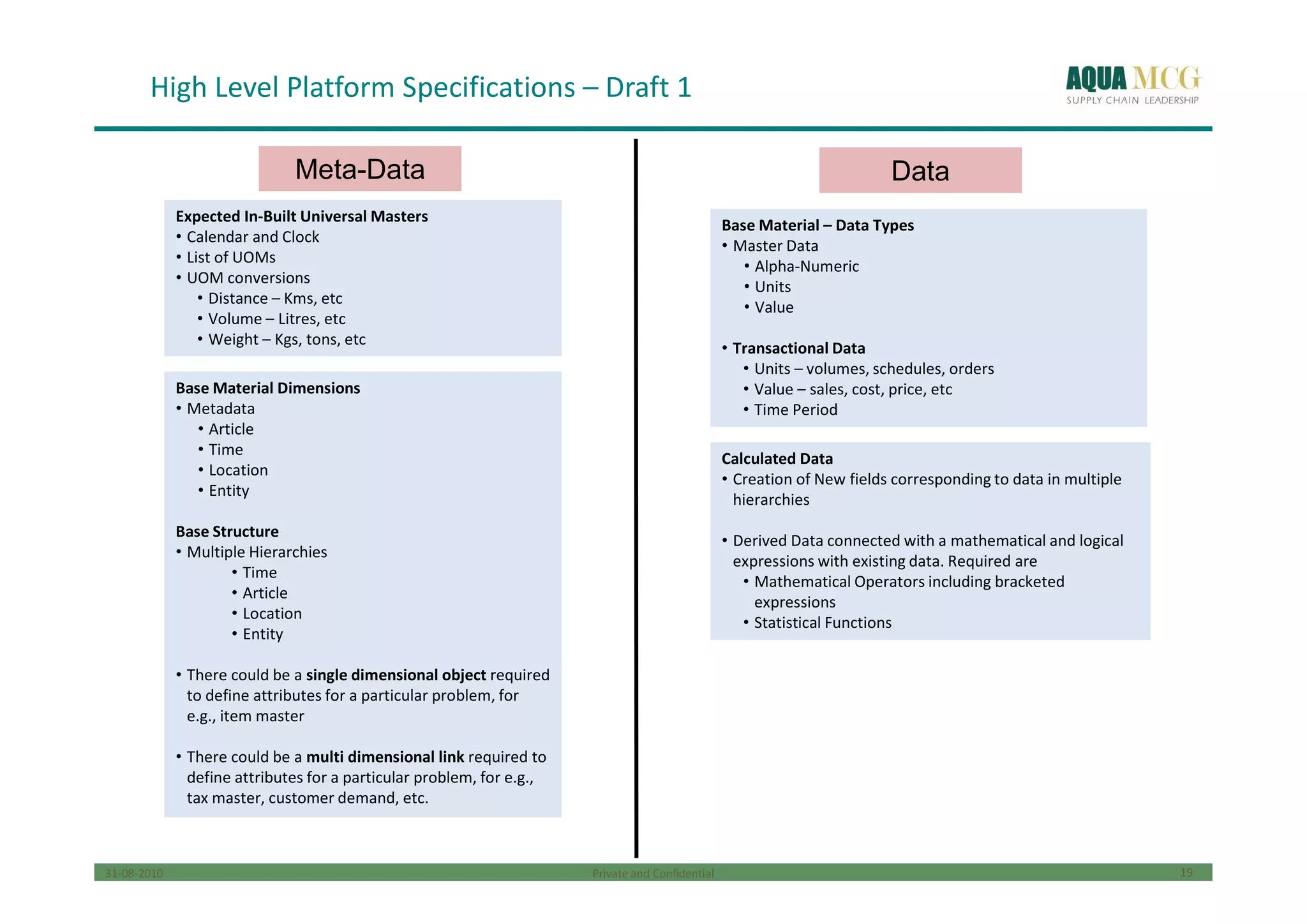
Platform – Derived Data
Functionality to create New Data and Define it using a mathematical or logical relationship with existing data.Functionality to create New Data and Define it using a mathematical or logical relationship with existing data.
Use Case 1
Formula within time
periods
Use Case 1
Formula within time
periods
Use Case 2
Formulae across
time periods
Use Case 2
Formulae across
time periods
Functionality Required:
• Pallet to choose data type and field and to choose mathematical / logical operators to build a formula linking the data
• Data should show the relative time period in brackets only in case the formula is across time periods
• Data should show the entire list of fields upon clicking on the data type
• UOM of the data should appear upon taking the pointer above the data field
• Saving of Several Versions of the Same Data based on Planning Cycle Month should be possible for some data
• Data Formula applicability for Past, Current or Future Time Periods or a combination of 2 or more
Data Types
Equation Constructs
Sales
Stock
Forecasts
Purchase
Orders
Transfer
Orders
Receipts
Requisitions
LHS Data
Field
Use Case 3
Formulae across
planning cycles
Use Case 3
Formulae across
planning cycles
Sales Value
Sales Volume Unit Price
% Sales
Increase Sales (0)( ) /
% Absolute
Forecast
Error
Forecast [-1]
Sales
Volume (0)
ABS ( )/
Sales (-1) Sales (0)
Use Case 4
Recursive Formulae
across time periods
Use Case 4
Recursive Formulae
across time periods
Sales
Volume (0)
Opening
Stock (1) Opening
Stock (0)
Forecast
(0)
Schedules
(0)](https://image.slidesharecdn.com/vembrief-200212180837/75/Virtual-Enterprise-Model-35-2048.jpg)


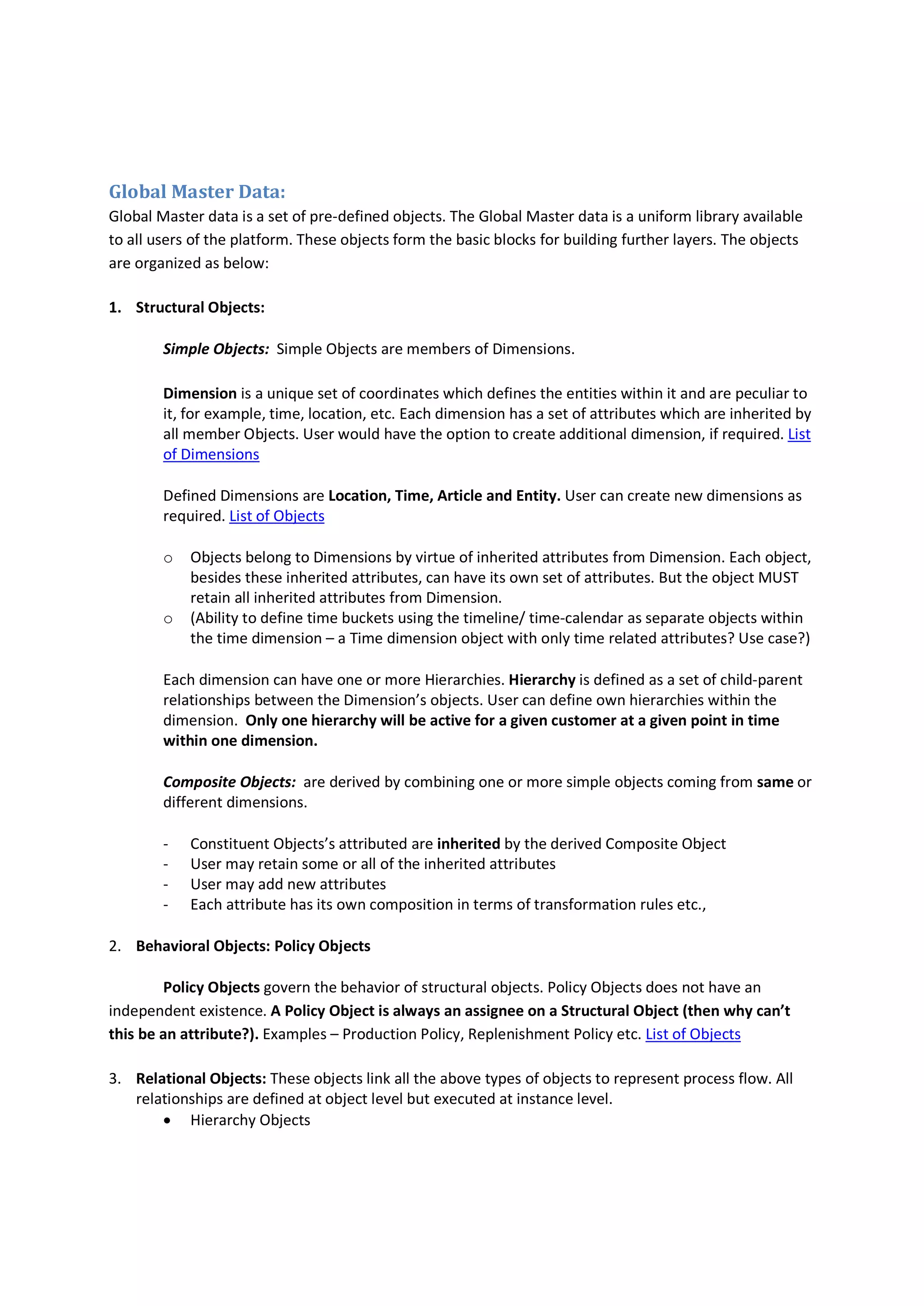
The document outlines the structure and functionality of global master data (GMD) and its components, including structural, behavioral, and relational objects tailored for platform users. It details how users can create virtual enterprise models (VEM) and input models, including steps for defining objects, attributes, hierarchies, and constraints, culminating in problem and solution models for optimization purposes. The document emphasizes the reusability of templates and the organization of data for effective problem-solving and reporting across various platform elements.