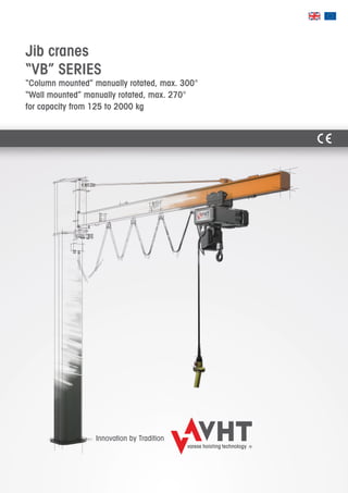
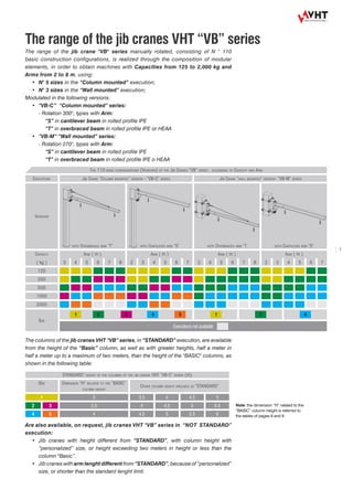
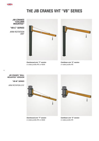
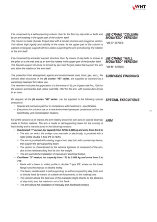
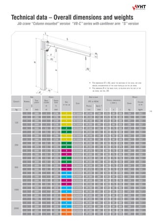
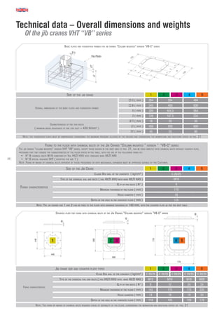
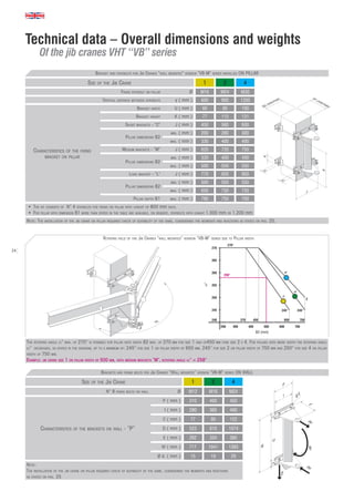
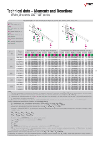
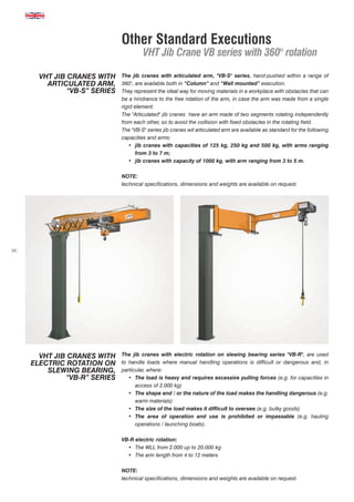
This document provides information on VHT's "VB" series of manually rotated jib cranes. The cranes come in "Column mounted" and "Wall mounted" versions, with maximum arm rotations of 300° and 270° respectively. They have capacities ranging from 125 to 2000 kg. The document discusses the cranes' modular design, safety features, intended uses, and technical specifications.
HES Cranes offers a broad variety of custom crane products, including Bridge, Workstation, Jib, Gantry, Indoor, Davit and Overhead Cranes. Call the experts today.
O’Brien Installations Limited (O’Brien) is a manufacturer of overhead cranes, jib cranes, workstation cranes, gantry cranes and a supplier of commercial doors and loading dock equipment, serving the industry for over 50 years, with sales, service and manufacturing facilities in Burlington, Ontario and Memramcook, New Brunswick and a sales and service office in Quebec, Quebec.
O‘Brien services include manufacturing, installation and service of under-running cranes, top-running cranes, gantry cranes, monorails, workstation bridge cranes, electric wire rope hoists, electric chain hoists, crane runway systems and conductor bar systems. We offer professional engineering services capable of designing material handling equipment to suit customer-specific requirements. We also offer 24-hour service and scheduled inspections to all makes and models of overhead cranes, hoists, industrial doors and dock equipment. We stock the largest inventory of spare parts in Ontario offering parts for all major brands of overhead cranes, hoists, commercial doors and dock equipment.
This document describes the design of a wall-mounted H-type jib crane with a maximum capacity of 1850 kg and a span of 7.25 meters. Key components include an H-beam structure, pivot assembly, manual trolley, motorized slewing, and a 68 kW hoist motor. Welding and structural analyses were conducted to ensure structural integrity under loading. Cost analyses were performed for the main components. The designed crane meets the client's specifications for lifting heavy loads in a manufacturing environment.
Workstation cranes can be manufactured to customer specifications for lifting loads up to 4000 lbs. They are available as free standing or ceiling mounted models with bridge spans up to 30 feet. The document provides information on the features and components of MET-TRACK brand workstation cranes, which are designed for ease of movement and reduced operator fatigue. Various configuration and mounting options are described.
1) The document discusses different types of cranes and their identification and load capacity requirements.
2) Crane operators must know how to use lifting charts and cranes require regular maintenance and inspections according to safety schedules.
3) Cranes have a number of safety devices incorporated in their design including overtravel switches, protections for bare conductors, clearly marked controls, and load indicators.
This document provides an overview of cranes and crane safety features. It defines what a crane is and describes the basic principle of how they lift loads. It then covers the different types of cranes including mobile, stationary, mechanical, hydraulic, lattice boom, and telescopic boom cranes. The document discusses crane components, configurations, basic operations like hoisting and slewing. It also outlines important safety features found on cranes like A2B systems, boom hoist limits, overload limits, and load moment indicators. Controlled load lowering is described as well.
Technoweigh India is an ISO 9001:2008 certified company, established in 1992, is an innovative state of art weighbridge manufacturers, supplier and Exporters of the wide range of Weighbridges, mobile weighbridges, portable weighbridges and electronic weighbridge. We at Technoweigh India always believe in 100% customer satisfaction and with the span of time, we are constantly upgrading our quality and style of manufacturing weighbridges. We have almost 20+ years of experience in this industry and we are proud to say that all our customers are 100% satisfied with the products we always work on technology-driven products and our line of weighbridge accessories like Load Cell, Jumbo Display and Junction box are originally manufactured by us. All our products whether it’s Mobile Weighbridge, Electronic Weighbridge or Portable Weighbridge are long-lasting and fulfil all the industrial and commercial requirements.
This document provides a project report comparing techniques and methods for constructing elevated metro rail corridors in Delhi, India. It discusses various structural forms, construction methodologies, environmental impacts, and costs. The report finds that segmental construction using precast concrete segments is preferable to cast-in-situ construction as it allows for very fast progress, minimal traffic disruptions, and flexibility. Single segment girders for dual tracks have advantages over separate girders in terms of construction simplicity and aesthetics. Erection of viaducts is done using specialized launching gantries. Environmental impacts of construction like noise and vibration must be mitigated.
The document discusses electric overhead cranes. It describes how cranes are used to move materials in industrial settings and can be powered electrically. There are different types of electric overhead cranes including single girder, double girder, gantry, and monorail cranes. The document provides details on crane components, specifications to consider when selecting a crane, classifications of cranes by service level, and methods for powering electric cranes.
This document provides information about launching girders for bridge construction. It discusses the necessary preparations before launching including completing abutments and piers. It describes the launching equipment used such as the steel launching girder, winches, and trolleys. The document outlines the process for shifting the launching girder and launching precast concrete girders segment by segment onto the bridge. It compares different launching techniques and discusses advantages such as allowing construction at any height and simultaneous work on substructure and superstructure.
Meeka Machinery Pvt. Ltd is a the best in the field of designing, manufacturing and supplying of Electric Wire Rope Hoist & Electrical Hoist for material handling.
Shri Om Sai Engineering is a material handling equipment company established in 1995 that manufactures and services goods lifts, trolleys, shutters, conveyors, cranes, stackers and other material handling equipment. Their annual turnover is 100 lakhs rupees and growing. Their clients include large companies like Siemens and Wockhardt. The company aims to be the most preferred supplier in their field through customer satisfaction, quality products, and long-lasting customer relationships. They offer various material handling equipment like cranes, stackers, lifts, wheels and more with specifications provided. Their objective is to improve efficiency, reliability and simplify processes for customers.
This document summarizes the precast segmental construction method for bridges. It was first used in Western Europe in the 1950s and involves casting concrete segments off-site, transporting them to the construction location, and erecting them using various methods like balanced cantilever, progressive placement, span-by-span, or incremental launching. Machinery like launchers, girders, cranes, and hydraulic jacks are used for erection. Additional steps include external prestressing and grouting. Precast segmental construction allows for longer spans, faster construction times, increased quality control, and is most suitable for long bridges.
Segmental bridge construction involves building bridges out of precast concrete segments. This allows for longer spans than traditional methods by reducing the need for intermediate piers. There are several techniques for segmental bridge construction including cast-in-place using form travelers, incremental launching where segments are cast and then pushed out over supports, and precast segment erection using launching girders. Segmental construction enables building bridges more quickly and over existing infrastructure with minimal traffic disruptions.
Track rollers with cylindrical or crowned outer ring – LR Series are cam rollers that can be used in heavy load tracks or as idler wheels. They feature internal structures like deep groove ball bearings or double row angular contact ball bearings and thick-walled outer rings to accommodate higher loads. They are precision-made from bearing steel and grease-lubricated to provide long service life under various conditions. Various seal options are available to prevent dust intrusion.
The document discusses the balanced cantilever method of bridge construction. It begins by explaining that this method is used for bridges with spans between 50-250m, and involves attaching precast or cast-in-place segments in an alternating manner from each end of cantilevers supported by piers. This method is well-suited for irregular spans, congested sites, and environmentally sensitive areas. It also discusses advantages like determinacy and reduced cracking risks. The document then goes into detail about construction sequences, member proportioning, superstructure types, and analysis of a specific balanced cantilever bridge in Kochi, India.
The document discusses crane jibs offered by Contatore Engineering for material handling. Crane jibs come in one, two, or three part models and can be customized. They have working load limits from 1-3 tonnes capacity depending on the machine. Crane jibs are securely constructed according to standards and come with a 3 tonne swivel safety hook. Diagrams show the designs of one, two, and three part crane jib models with their dimensions and load limits.
The document provides specifications for two surface mounted 4-post lift models, the Q4P12E and extended length Q4P12X, both with a lifting capacity of 12,000 lbs. Key features include solid piece column construction for rigidity, 14 locking positions, oversized pulleys for long life, adjustable runways accommodating various tread widths, and optional accessories like rolling jacks and an alignment kit. Dimensions listed include overall lengths of 20' 4 1/2" for the Q4P12E and 22' 8" for the Q4P12X.
Case study bridge construction upto pier and road constructionSatish Kambaliya
The document provides details about the construction of a flyover bridge along the SP Ring Road in Ahmedabad, India. Some key details include:
- The project involves constructing a 1,415 meter long flyover bridge with 30 piers and 32 pile caps.
- Pile construction is a major aspect of the project, with 408 piles of 1,200 mm diameter being constructed using a hydraulic rig by boring and concreting.
- Other construction activities discussed include pile cap construction, pier construction, road construction and the use of various equipment.
- The flyover is expected to improve connectivity and prevent traffic congestion along the busy SP Ring Road in Ahmedabad.
The balanced cantilever method is used to construct bridges with spans between 50-250m. It involves erecting segments on each side of the pier in a balanced sequence to minimize load imbalance and bending in the piers. This method is advantageous for long spans, marine environments, and where access under the deck is difficult. The cantilever lengths are typically 0.20-0.30 of the main span. Segment construction proceeds until the midspan point is reached, where the balanced pair is closed. The key advantages are single-sided support during construction and uniform construction. However, it is also very expensive and complicated to construct.
This document discusses different types of overhead cranes called EOT cranes. It describes single girder EOT cranes that can lift up to 20 tons and have a span of up to 40 meters, and double girder EOT cranes that can lift up to 200 tons and have a span of up to 65 meters. The main difference between single and double girder cranes is the hook height, which is typically 18-36 inches higher for double girder cranes. Some common causes of crane failure are also listed, including electrocution, crushing during assembly/disassembly, failure of the boom or cable, crane tip over, and falls.
Introduction to Heavy Construction MachineryFazal-E- Jalal
The document discusses heavy construction machinery, providing an introduction to various types of machines used in construction projects including excavators, loaders, dump trucks, pavers, cranes, and others. It covers the historical development and improvements of these machines, from early steam-powered dredges to modern diesel-powered equipment with advanced technologies. The document also discusses topics like planning equipment usage, safety, and outlines the course which will provide further information on different types of heavy construction machinery.
This document provides an overview of lathe operations, including:
1. It describes the various types of lathes such as engine lathes, turret lathes, and special purpose lathes like jeweler's lathes.
2. It explains the essential features of lathes like the bed, ways, headstock, and tailstock.
3. It discusses lathe safety and proper maintenance of lathe parts to ensure accurate machining.
The document discusses lifting arrangements on cargo ships, including:
1) Cranes have largely replaced shipyard-built derricks due to being less labor intensive, faster, and taking up less deck space, though they require more maintenance.
2) Shipowners specify lifting devices and shipbuilders design derrick rigs. Masts support derricks and are constructed of welded tubular steel sections.
3) Forces on derrick components like the boom and span depend on factors like boom length and angle topped. Initial tests subject derricks to loads exceeding their safe working load.
Breakout Session: Design, Fabrication and Testing of Cantilever Beams and Triangle Plates
Cantilever beams and triangle plates are valuable specialty rigging tools, but the engineering fundamentals behind their design and use are simpler than they may appear. This presentation will provide examples of commonly used rigging applications and will identify resources for design, fabrication, load testing and lift planning.
Speaker: Chad Fox, PE, Project Manager, ruby+associates
This document provides information on various pillar-mounted, wall-mounted, and slewing jib cranes from Demag Cranes & Components. It discusses Demag's history and system philosophy in developing cranes. It then provides details on several crane models, including their specifications, options, and applications. The cranes can improve workplace efficiency and ergonomics by automating material handling tasks.
This document discusses overhead cranes and jib cranes. It describes Cranoist engineers as specialists in manufacturing and supplying industrial cranes, crane parts, and mechanical handling equipment. They provide new and refurbished overhead cranes, gantry cranes, and jib cranes as well as crane servicing and repairs. The cranes are designed for accuracy and productivity with features like magnetic or hydraulic brakes, master control switches, and drum controllers to improve effectiveness and safety.
This document provides information on various lifting and material handling products from CarlStahl Craftsman, including electric chain hoists, wire rope hoists, overhead cranes, jib cranes, monorail cranes, and lifting fixtures. The company offers a wide range of hoists and cranes with different load capacities, models, features and options to suit various industrial applications. It also provides related accessories, infrastructure, erection and commissioning services to deliver complete lifting solutions.
This document provides a disclaimer and legal notice for Vishay Precision Group. It states that all product specifications and data are subject to change without notice, and that VPG disclaims any liability for errors in product information or specifications. It also clarifies that no warranties are provided by this document and that VPG provides no warranty beyond what is specified in the terms of purchase. Customers use VPG products at their own risk for life-critical applications unless authorized in writing by VPG.
This document summarizes the design and behavior of jib cranes. It discusses the background and history of jib cranes, describes the main types of jib cranes including free standing, wall mounted, wall bracket, and mast style cranes. It also outlines the typical applications of jib cranes in industrial settings. Finally, it reviews the relevant Canadian design code specifications for loads, capacities, and structural design of jib cranes.
The document provides an introduction and overview of jib cranes manufactured by Gorbel. It discusses the different types of jib cranes Gorbel offers, including I-beam, enclosed track, and articulating jib cranes. It also covers important considerations for selecting a jib crane, such as the type of structural support available, powered operation requirements, and cost. Key specifications and performance characteristics for different crane types are also outlined.
AViTEQ - Compact feeder drive is used everywhere fine-grained bulk materials and not too unwieldy mass parts must be delivered, conveyed, dosed, added or assigned from storage tanks. AViTEQ has led the way in producing these devices and drives in Germany on a highest level standard.
The document discusses several attachments for forklifts used in handling glass, including carriage mounted jibs, spreader beams, telescopic jibs, hydraulic glass handlers, glass clamps, and glass stabilizers. The attachments are designed to safely lift, shift, and transport glass. Specifications such as weight, dimensions, capacity, and material finish are provided for each attachment type and model.
This document provides a legal disclaimer notice for Vishay Precision Group. It states that all product specifications and data are subject to change without notice. It disclaims any liability for errors in product information and specifies that the product specifications do not modify the standard terms of purchase. It also disclaims implied warranties and liability for damages arising from application or use of products not expressly designed for life-saving applications. The notice specifies that product names and markings may be trademarks of their respective owners.
Ambica Engineering Company is leading Crane Company in Ahmedabad, Gujarat, India. It's offered cranes are EOT Crane, Single & Double Girder EOT Crane, Goliath Gantry Crane, Electric wire rope Hoist and other material handling equipments with excellent quality and largely available in global market.
O’Brien’s offers one of the largest selections of jib cranes available in North America. We have the solution for your jib crane applications from our wide range of standard models or from our robust jib models designed for those very long and tall jib cranes with exceptionally high lifting capacities.
SCS Heavy Lifts & Transports provides heavy lifting and transport services using equipment like hydraulic lifting gantries, jacks, skids, and strand jacks. It handles a wide range of projects in industries such as civil, power generation, shipyards, oil and gas, ports, offshore, nuclear, and production plants. Services include transport, lifting, skidding, jacking, assembly, and weighing of heavy objects.
The document discusses ASME B30.5, the safety standard for mobile and locomotive cranes. It provides definitions for key terms, the scope of equipment covered, and requirements for load ratings, construction, and characteristics. The standard requires load rating charts showing the full range of rated capacities based on factors like boom length, outrigger position, and radius. The charts must be clearly displayed and include warnings or limitations. Requirements are provided for load ratings determined by stability or structural competence, and diagrams must be supplied by the manufacturer.
This document discusses tower cranes used in construction. It begins by introducing tower cranes and their main components, including the mast, slewing unit, operating cabin, jib, hook, and counterweights. It then describes the functions of tower cranes in lifting building materials. The document goes on to provide more detail on specific types of tower cranes like luffing jib and self-erecting cranes. It concludes by covering regulations, safety considerations, and factors to consider when selecting a tower crane for a project.
Design, Simulation & Optimization of Gravity Spiral Roller Conveyer with Auto...IRJET Journal
The document describes the design, simulation and optimization of a vertical gravity spiral roller conveyor system with an automatic collision avoidance system for transporting boxes between 5 floors of a building. Key aspects include:
1. Designing the helical angle, roller assembly, frame and other parts using CAD software and analyzing them through finite element analysis for strength and modal properties.
2. Optimizing the design for weight reduction and cost effectiveness while maintaining required strength and durability.
3. Developing an automatic collision avoidance system using ultrasonic sensors and an Arduino board to prevent collisions between boxes entering and exiting each floor.
ottobre 2016 - articolo Saipem bollettino SPEAndrea Intieri
This document provides an overview of flexible pipe and umbilical laying systems used in the offshore oil and gas industry. It describes the main components of flexible laying systems, including storage systems like reel hub drives and carousels, product handling systems, and horizontal and vertical laying systems. It highlights some of the capabilities of state-of-the-art flexible laying vessel Normand Maximus, including its 550 tonne vertical laying system and under deck storage basket.
Lecture 6 s.s.iii Design of Steel Structures - Faculty of Civil Engineering IaşiUrsachi Răzvan
The document discusses the design of runway girders that support overhead cranes. It describes various types of runway girder configurations including single plate girders, built-up box sections, and lattice girders. It also outlines the loads that act on these girders including the self-weight of the girder and rails, as well as vertical and horizontal forces from the moving crane. Design is checked against limit states including bending capacity, buckling, fatigue limits, and serviceability deflections. Equations are provided to calculate stresses in different parts of the girder from these loads.
Started to create milestones, we SEEMA CONVEYOR BELTS & SYSTEMS PVT. LTD. marked our presence in the year 1995 and operates in the manufacturing/servicing of Ultrasonically welded cleated Belts since 16 years. Our quality services/products have always won us many appreciations from our clients. Our spontaneous performance and confident approach in offering the excellent range of Ultrasonically welded cleated Belts that has made us to deepen our roots in the market. We SEEMA CONVEYOR BELTS & SYSTEMS PVT. LTD. breathe with the aim to satisfy our clients with our smart products/services. We are a unit of highly experienced professionals who all contribute best of their potentials to offer high efficiency.
Null Bangalore | Pentesters Approach to AWS IAMDivyanshu
#Abstract:
- Learn more about the real-world methods for auditing AWS IAM (Identity and Access Management) as a pentester. So let us proceed with a brief discussion of IAM as well as some typical misconfigurations and their potential exploits in order to reinforce the understanding of IAM security best practices.
- Gain actionable insights into AWS IAM policies and roles, using hands on approach.
#Prerequisites:
- Basic understanding of AWS services and architecture
- Familiarity with cloud security concepts
- Experience using the AWS Management Console or AWS CLI.
- For hands on lab create account on [killercoda.com](https://killercoda.com/cloudsecurity-scenario/)
# Scenario Covered:
- Basics of IAM in AWS
- Implementing IAM Policies with Least Privilege to Manage S3 Bucket
- Objective: Create an S3 bucket with least privilege IAM policy and validate access.
- Steps:
- Create S3 bucket.
- Attach least privilege policy to IAM user.
- Validate access.
- Exploiting IAM PassRole Misconfiguration
-Allows a user to pass a specific IAM role to an AWS service (ec2), typically used for service access delegation. Then exploit PassRole Misconfiguration granting unauthorized access to sensitive resources.
- Objective: Demonstrate how a PassRole misconfiguration can grant unauthorized access.
- Steps:
- Allow user to pass IAM role to EC2.
- Exploit misconfiguration for unauthorized access.
- Access sensitive resources.
- Exploiting IAM AssumeRole Misconfiguration with Overly Permissive Role
- An overly permissive IAM role configuration can lead to privilege escalation by creating a role with administrative privileges and allow a user to assume this role.
- Objective: Show how overly permissive IAM roles can lead to privilege escalation.
- Steps:
- Create role with administrative privileges.
- Allow user to assume the role.
- Perform administrative actions.
- Differentiation between PassRole vs AssumeRole
Try at [killercoda.com](https://killercoda.com/cloudsecurity-scenario/)
Redefining brain tumor segmentation: a cutting-edge convolutional neural netw...IJECEIAES
Medical image analysis has witnessed significant advancements with deep learning techniques. In the domain of brain tumor segmentation, the ability to
precisely delineate tumor boundaries from magnetic resonance imaging (MRI)
scans holds profound implications for diagnosis. This study presents an ensemble convolutional neural network (CNN) with transfer learning, integrating
the state-of-the-art Deeplabv3+ architecture with the ResNet18 backbone. The
model is rigorously trained and evaluated, exhibiting remarkable performance
metrics, including an impressive global accuracy of 99.286%, a high-class accuracy of 82.191%, a mean intersection over union (IoU) of 79.900%, a weighted
IoU of 98.620%, and a Boundary F1 (BF) score of 83.303%. Notably, a detailed comparative analysis with existing methods showcases the superiority of
our proposed model. These findings underscore the model’s competence in precise brain tumor localization, underscoring its potential to revolutionize medical
image analysis and enhance healthcare outcomes. This research paves the way
for future exploration and optimization of advanced CNN models in medical
imaging, emphasizing addressing false positives and resource efficiency.
Software Engineering and Project Management - Introduction, Modeling Concepts...Prakhyath Rai
Introduction, Modeling Concepts and Class Modeling: What is Object orientation? What is OO development? OO Themes; Evidence for usefulness of OO development; OO modeling history. Modeling
as Design technique: Modeling, abstraction, The Three models. Class Modeling: Object and Class Concept, Link and associations concepts, Generalization and Inheritance, A sample class model, Navigation of class models, and UML diagrams
Building the Analysis Models: Requirement Analysis, Analysis Model Approaches, Data modeling Concepts, Object Oriented Analysis, Scenario-Based Modeling, Flow-Oriented Modeling, class Based Modeling, Creating a Behavioral Model.
Generative AI Use cases applications solutions and implementation.pdfmahaffeycheryld
Generative AI solutions encompass a range of capabilities from content creation to complex problem-solving across industries. Implementing generative AI involves identifying specific business needs, developing tailored AI models using techniques like GANs and VAEs, and integrating these models into existing workflows. Data quality and continuous model refinement are crucial for effective implementation. Businesses must also consider ethical implications and ensure transparency in AI decision-making. Generative AI's implementation aims to enhance efficiency, creativity, and innovation by leveraging autonomous generation and sophisticated learning algorithms to meet diverse business challenges.
https://www.leewayhertz.com/generative-ai-use-cases-and-applications/
Build the Next Generation of Apps with the Einstein 1 Platform.
Rejoignez Philippe Ozil pour une session de workshops qui vous guidera à travers les détails de la plateforme Einstein 1, l'importance des données pour la création d'applications d'intelligence artificielle et les différents outils et technologies que Salesforce propose pour vous apporter tous les bénéfices de l'IA.
Prediction of Electrical Energy Efficiency Using Information on Consumer's Ac...PriyankaKilaniya
Energy efficiency has been important since the latter part of the last century. The main object of this survey is to determine the energy efficiency knowledge among consumers. Two separate districts in Bangladesh are selected to conduct the survey on households and showrooms about the energy and seller also. The survey uses the data to find some regression equations from which it is easy to predict energy efficiency knowledge. The data is analyzed and calculated based on five important criteria. The initial target was to find some factors that help predict a person's energy efficiency knowledge. From the survey, it is found that the energy efficiency awareness among the people of our country is very low. Relationships between household energy use behaviors are estimated using a unique dataset of about 40 households and 20 showrooms in Bangladesh's Chapainawabganj and Bagerhat districts. Knowledge of energy consumption and energy efficiency technology options is found to be associated with household use of energy conservation practices. Household characteristics also influence household energy use behavior. Younger household cohorts are more likely to adopt energy-efficient technologies and energy conservation practices and place primary importance on energy saving for environmental reasons. Education also influences attitudes toward energy conservation in Bangladesh. Low-education households indicate they primarily save electricity for the environment while high-education households indicate they are motivated by environmental concerns.
Gas agency management system project report.pdfKamal Acharya
The project entitled "Gas Agency" is done to make the manual process easier by making it a computerized system for billing and maintaining stock. The Gas Agencies get the order request through phone calls or by personal from their customers and deliver the gas cylinders to their address based on their demand and previous delivery date. This process is made computerized and the customer's name, address and stock details are stored in a database. Based on this the billing for a customer is made simple and easier, since a customer order for gas can be accepted only after completing a certain period from the previous delivery. This can be calculated and billed easily through this. There are two types of delivery like domestic purpose use delivery and commercial purpose use delivery. The bill rate and capacity differs for both. This can be easily maintained and charged accordingly.
Introduction- e - waste – definition - sources of e-waste– hazardous substances in e-waste - effects of e-waste on environment and human health- need for e-waste management– e-waste handling rules - waste minimization techniques for managing e-waste – recycling of e-waste - disposal treatment methods of e- waste – mechanism of extraction of precious metal from leaching solution-global Scenario of E-waste – E-waste in India- case studies.
Embedded machine learning-based road conditions and driving behavior monitoringIJECEIAES
Car accident rates have increased in recent years, resulting in losses in human lives, properties, and other financial costs. An embedded machine learning-based system is developed to address this critical issue. The system can monitor road conditions, detect driving patterns, and identify aggressive driving behaviors. The system is based on neural networks trained on a comprehensive dataset of driving events, driving styles, and road conditions. The system effectively detects potential risks and helps mitigate the frequency and impact of accidents. The primary goal is to ensure the safety of drivers and vehicles. Collecting data involved gathering information on three key road events: normal street and normal drive, speed bumps, circular yellow speed bumps, and three aggressive driving actions: sudden start, sudden stop, and sudden entry. The gathered data is processed and analyzed using a machine learning system designed for limited power and memory devices. The developed system resulted in 91.9% accuracy, 93.6% precision, and 92% recall. The achieved inference time on an Arduino Nano 33 BLE Sense with a 32-bit CPU running at 64 MHz is 34 ms and requires 2.6 kB peak RAM and 139.9 kB program flash memory, making it suitable for resource-constrained embedded systems.
1. Jib cranes
“VB” SERIES
“Column mounted” manually rotated, max. 300°
“Wall mounted” manually rotated, max. 270°
for capacity from 125 to 2000 kg
Innovation by Tradition
2.
3. 3
VHT Varese Hoisting Technology S.r.l., thanks to the long experience of its engineers
of technical design and production in lifting equipment, is able to offer in the world’s
market the most modern technical-technological compendium of hoisting equipment in
the global market, reliable and economical.
The jib cranes “VB” series, for capacity from 125 to 2.000 kg, are designed and
manufactured using cutting-edge design techniques, 3D CAD system integrated with
finite element calculations. The electric jib cranes “VB” series overcome rigorous
life and reliability testing in our modern “Experience Department”, in order to assure
compliance to the standard rules and project data, within the highest quality standards.
The VHT Varese Hoisting Technology S.r.l. produces, in a highly serialized way, jib
cranes "VB" series, with the benefit of industrialized production processes controlled by
a quality system conducted according to UNI EN ISO 9001:2000
The jib cranes VHT “VB” series, manually rotated, available in “Column mounted” and
“Wall mounted” execution, are designed to handle goods into a plant or in an outdoor
square or to serve workstations.
The jib cranes are characterized by three functions:
• lift vertically a load by means of a unit that generally consists of a chain hoist and
specific lifting accessories;
• move the load by means of a trolley, electric or manual, that runs on the arm of the
jib crane;
• rotate the load around the rotating axe of the arm by means of the pushing force of
the load itself, serving the underlying circular area, bounded by the rotating radius
of the arm.
The jib cranes in “Column mounted” execution are generally provided for fixing to the
ground; the self-supporting column can be fixed to the ground by means of stay bolts,
on suitable foundation plinth or, after having checked the suitability, with chemical bolts
with suitable counter plate.
The jib cranes in “Wall mounted” execution are generally provided to be placed to
a vertical surface of an existing structure (eg.: walls, pillars, machine bodies, etc..), by
means of a system of brackets and tie rods or with fixing screws.
A RIGOROUS PROCESS
CONTROL
THE JIB CRANES VHT
“VB”SERIES
MANUALLY ROTATED,
COLUMN MOUNTED
AND WALL MOUNTED
EXECUTION
“Innovation by tradition”
4. 4
The jib cranes “VB” series, manually rotated, “Column mounted and “Wall mounted”
execution, designed and produced by VHT for capacity from 125 to 2000 kg, as well as
being characterized by a modern design, guaranteed high security and reliability, thanks
to evolutionary project conducted on the basis of a strict "Analysis FMECA" (Failure
Mode, Effects, and Criticality Analysis)”.
The innovative design, which allows the maximum arm rotation (300° for all the column-
mounted versions and 270° for the wall-mounted versions), gives to the jib cranes
VHT “VB” series an extraordinary modernity as evidenced by an advanced technical
peculiarities consisting of the following devices and requirements PROVIDED AS
STANDARD:
Arm rotating limit device (patent VHT pending).
The system has been designed in order to limit the arm rotation to avoid possible
interferences and/or collisions against fixed structures of the operating area.
This device, easily adjustable for the complete rotating arm range, is therefore a required
safety component, in accordance with the existing European legislation, for the design
and construction of machinery (Directive Machine 2006/42/CE - Annex I – Essential
safety requirement 4.1.2.6. – Control of movements) .
Since the device is supplied as standard, its installation doesn’t require a “ declaration of
suitability” from the Customer/Installer.
Jib cranes “VB” series
Safety, reliability and…competitive advantages
SAFETY AND RELIABILITY
OF THE JIB CRANES vht
3 YEARS WARRANTY FROM
DELIVERY DATE
5. 5
Device for adjusting the flatness of arms overbraced version.
The system allows to set the best value of counterslop of the arm according with the
deflection caused by the arm lenght itself and from the height of any column.
Reduction of the pushing forces and noise in the traverse movements.
The low friction between the wheels and the sliding surfaces they are located in,
gives the maximum smoothness and quietness in the push trolleys movement.
In fact the high quality and resistance beams used for the arms are selected with
tight tolerances and subjected to sandblasting cycles and are therefore marked by
sliding surfaces with low roughness.
Furthermore, to have high smoothness and quietness, the push trolleys, up to 1.000
kg capacity, are provided with wheels in polyamide resin rotating on self-lubricated
ball bearings and are provided with guide rollers, in order to avoid any shaving
friction.
Optimization of time and costs of regular inspections of the trolleys.
As the wheels of the trolleys run on the flange of the beam of the arm, they are easily
inspected without disassembly.
6. 6
Modular design with modular elements.
The system allows to:
• Have simple and compactable elements, disassembled, easy to be packaged,
characterized by regular and elementary shapes (such as parallelepipeds) and,
therefore, easily and economically handled and delivered.
• Semplify and secure the installation steps of the single elements composing
the over-braced arm, in different executions of column-mounted or wall-mounted
jib cranes.
• Reconfigure and redeploy the jib crane, also after the purchase, following any
user’s requirement , thanks to a modular design and the use of profiled beams for
the arms construction.
For instance it’s always possible(in any time and directly on site) to:
- Replace the push trolley with an electric one;
- Electrify the rotation of the arm with the aid of a dedicated “kit”.
7. 7
The range of the jib crane "VB" series manually rotated, consisting of N ° 110
basic construction configurations, is realized through the composition of modular
elements, in order to obtain machines with Capacities from 125 to 2,000 kg and
Arms from 2 to 8 m, using:
• N° 5 sizes in the “Column mounted” execution;
• N° 3 sizes in the “Wall mounted” execution;
Modulated in the following versions:
• “VB-C” “Column mounted” series:
- Rotation 300°, types with Arm:
“S” in cantilever beam in rolled profile IPE
“T” in overbraced beam in rolled profile IPE or HEAA
• “VB-M” “Wall mounted” series:
- Rotation 270°, types with Arm:
“S” in cantilever beam in rolled profile IPE
“T” in overbraced beam in rolled profile IPE o HEAA
The columns of the jib cranes VHT “VB” series, in “STANDARD” execution, are available
from the height of the “Basic” column, as well as with greater heights, half a meter in
half a meter up to a maximum of two meters, than the height of the "BASIC" columns, as
shown in the following table:
Are also available, on request, jib cranes VHT “VB” series in “NOT STANDARD”
execution:
• Jib cranes with height different from “STANDARD”, with column height with
“personalized” size, or height exceeding two meters in height or less than the
column "Basic”.
• Jib cranes with arm lenght different from “STANDARD”, because of “personalized”
size, or shorter than the standard lenght limit.
The range of the jib cranes VHT “VB” series
The 110 basic configurations (Versions) of the Jib Cranes “VB” series , according to Capacity and Arm
Executions Jib Crane “Column mounted” version - “VB-C” series Jib Crane “wall mounted” version- “VB-M” series
Versions
with Overbraced arm “T” with Cantilever arm “S” with Overbraced arm “T with Cantilever arm “S”
Capacity Arm ( m ) Arm ( m ) Arm ( m ) Arm ( m )
( kg ) 3 4 5 6 7 8 2 3 4 5 6 7 3 4 5 6 7 8 2 3 4 5 6 7
125
250
500
1000
2000
Size
Executions not available
Note: the dimension “H” related to the
“BASIC” column height is referred to
the tables of pages 8 and 9
STANDARD” height of the columns of the jib cranes VHT “VB-C” series (m)
SIze Dimension “H” relative to the “BASIC”
column height
Other column height available as “STANDARD”
1 3 3.5 4 4.5 5
2 3 3.5 4 4.5 5 5.5
4 5 4 4.5 5 5.5 6
8. 8
The jib cranes VHT “VB” series are designed and classified in consideration of standard
EN 13001-1, in order to operate according to the parameters relating to the service
group A5 of ISO 4301-1.
In order to choose the right jib crane for the required service it’s important to consider
the following factors:
1. The capacity of the jib crane: is determined by the maximum load to lift
2. The loading rate (Q): is the stress level due to percentage of use of the capacity
(average of the loads to be lifted)
3. The functional parameters: are the operating conditions characterizing the use
of the jib crane or:
a. Functional dimensions: the height of the arm (determining the lifting height of
the hoist) and its cantilever (outreach) must be selected in order to ensure the
functional coverage of the space to be served, in consideration of neighboring
space;
b. Type of load: if it’s delicate or less, determines for its positioning the choice of
the speed of movement (lifting and translation) more suitable. In some cases it
is necessary to use a two-speed hoist with slow speed positioning.
c. Area of use: the jib crane is characterized by its conception, by intrinsic high
elasticity that is even more evident when it is used to handle loads close to the
maximum capacity and/or with mainly location in the top of the arm.
d. Ambient condition of use: the jib cranes are designed for indoor use and /
or covered area, protected from the weather and in absence of wind. In case
of outdoor use measures must be taken in relation to the surface treatment
(sandblasting - painting) as well as a parking brake arm and a suitable protection
cover for the trolley hoist.
e. Frequency and mode of use: determine the correct choice of the type
of translation and rotation, which can be manual or electrical in relation
to the characteristics of the load to be handled and the frequency of use.
If the use is very heavy (frequent and/or repeated switching) with loads close
to the maximum capacity, the resulting tiring of the operator due to manual
handling must be evaluated, in consideration of the recommendations referred
to the following table
Classification, criteria of choice and limit use
Capacity Arm ( m )
Recommendations of use
(kg) 2 3 4 5 6 7 8
125 field of optimal use for movements of translation and / or rotation
of loads normally next to the maximum load and / or with frequent
switching
250
500
field of Use allowed for movements of translation and / or rota-
tion of loads occasionally next to the maximum load with sporadic
switching
1000
2000
9. 9
f. the maximum number of working cycles CA, calculated with the following
formula:
The type of jib crane VHT "VB" series is selectable in the table “FEATURES AND
SPECIFICATIONS", based on the capacity of the crane as well as other factors, determined
or calculated, that characterize its intended use (Loading rate and ISO Service Group)
Esempio:
• Execution of the jib crane “Column mounted” Jib crane - “VB-C” series
• Column height A ( m ) = 3,5 m
• Jib crane version with Overbraced arm “T”
• Arm length and medium run ( Xlin
) Arm ( m ) = 5 m, with medium run of the
load on the arm Xlin
= 2 m
• Average angular rotation ( Xang
) Xang
= 80°
• Maximum load to be lifted: 500 kg Capacity of the jib crane “VB” series =500 kg
• Average of the loads to to be lift: 300 kg Loading rate = Q3
• Up/down lifting operations per hour N° cycles per hour C/h = 20
• Use on a working shift Ti (hours) = 8
• Working days per year: 250 D/year = 250
Calculation of the number of operating cycles ( CA
) executable in 10 years:
CA
= C/h x Ti x G/anno x 10 = 20 x 8 x 250 x 10 = 400.000 cycles
(corresponding to class U5 of standard EN 13001-1)
On the basis of the determined and calculated factors, the service group is: Q3 - U5 - Dlin
2
- Dang3
, 2 according to the standard EN 13001-1, corresponding to ISO M5 .
Therefore, as shown in the tables “TECHNICAL DATA” of pag. 10 e 11, the jib crane
suitable for the use will be: BC335T05.
Operating cycles in the Service Group ISO A5 in relation to the Loading rate ( Q )
Loading rate ( Q ) according to standard EN 13001-1
Operating cycles of the jib crane ( n° ) in the service group A5 according ISO 4301-1
Q % of the max. load (use % of the capacity)
Q0
> 25% ≤ 32% > 2.000.000 ≤ 4.000.000
Q1
> 32% ≤ 40% > 1.000.000 ≤ 2.000.000
Q2
> 40% ≤ 50% > 500.000 ≤ 1.000.000
Q3
> 50% ≤ 63% > 250.000 ≤ 500.000
Q4
> 63% ≤ 80% > 125.000 ≤ 250.000
Q5
>80% ≤ 100% > 63.000 ≤ 125.000
CA= C/h x Ti x G/year x A
where: C/h = Operating cycles ( N° cycles per hour )
It’s the number of complete up/down operations per hour
Ti = Hoist running time ( hours )
It’s the hoist running time in the whole day
G/anno = Giorni per anno (N°)
È il numero di giornate lavorative annue di utilizzo della macchina
A = Years of service ( N° years )
It’s the number of years, not less than 10, for which the life of the machine is calculated
10. 10
Overbraced arm “T” version
in rolled profile IPE or HEAA
Overbraced arm “T” version
in rolled profile IPE or HEAA
Cantilever arm “S” version
in rolled profile IPE
Cantilever arm “S” version
in rolled profile IPE
THE JIB CRANES VHT “VB” SERIES
JIB CRANES
“COLUMN
MOUNTED”
“VB-C” SERIES
Arm rotation
300°
JIB CRANES “WALL
MOUNTED” VERSION
“VB-M” SERIES
Arm rotation 270°
11. 11
It is composed by a self-supporting column, fixed to the floor by stay bolts or bolts and
by an arm rotating in the upper part of the column itself.
The column is made of press forged steel with a tubular structure and polygonal section.
This allows high rigidity and stability of the crane. In the upper part of the column is
welded a triangular support with two plates supporting the arm and allowing the rotation
of the arm itself.
It is composed by a bracket support structure, fixed by means of stay bolts or screws to
the pillar or to the wall and by an arm that rotates in the upper part of the bracket itself.
The bracket support structure is formed by two steel forged plates that support the arm
and allow the rotation of the arm itself.
The protection from atmospheric agents and environmental ones (dust, gas, ecc.), the
welded steel structures of the Jib cranes “VB” series, are supplied as standard by a
varnishing treatment for indoor use.
The treatment includes the application of a thickness of 60 μm of grey coat RAL 7005 for
the column and bracket and yellow coat RAL 1007 for the arm, with consecutive drying
in an oven.
On request, all the jib cranes “VB” series can be supplied in the following special
executions:
• Special anti-corrosive paint or in compliance with Customer’s specificatios.
• Executions for outdoor use or in sea environment (example: protection roof for the
hoist/trolley, anti-condensation heaters).
For all the versions of jib cranes, the arm rotating around its own axis on special bearings
made in friction material. The arm is made in self-supporting beam for the running of
hoist/trolley and is manufactured in the following versions:
• Overbraced “T” version, for capacity from 125 to 2.000 kg and arms from 3 to 8 m
• The arm, on which the trolleys runs manually or electrically, is provided with a
roller profile double T, type IPE or HEAA.
• The arm is provided with rotating support and stay bolt, with counterslop device,
that support the self-supporting beam.
• The version is characterized by the extreme lightness of movement of the arm,
due to low inertia resulting from its own low weight .
• The arm permits the installation of manual and electrical trolleys.
• Cantilever “S” version, for capacity from 125 to 2.000 kg and arms from 2 to
7 m
• Made with a beam in rolled profile in double T type IPE, where on the lower
flange runs the manual or electric trolley.
• The beam, cantilevered, is self-supporting, so without supporting stay bolts, and
is directly fixed, by means of suitable reinforcements, to the rotating tube.
• This version allows the best use of the available height (thanks to the absence
of stay bolts) and the maximum run of the hook.
• The arm allows the installation of manually and electrically trolleys
JIB CRANE “COLUMN
MOUNTED” VERSION
“VB-C” SERIES
JIB CRANE “WALL
MOUNTED” VERSION
“VB-M” SERIES
arm
Surfaces finishing
Special executions
12. 12
The arms of the Jib cranes “VB” series are provided, in all versions, with a braking
system, or a friction brake, in plastic material, that allows the regulation of the rotating
force of the arm and ensures the stability.
It is designed to power the hoist and/or the electric trolley, runs along the arm of the
jib crane. It uses a connection box for the connection between the line and the power
festoon, fixed in the top of the column of the of the jib “VB-C” series or near the bracket
in the wall mounted version “VB-M” series.
The Jib cranes “Column mounted ”VB-C” series can be supplied, on request, with
padlocked main switch with fuses.
The distribution of energy is done by means of festoons cable, flame retardant, that runs
on the arm by means of slides, sliding on rope fixed under the beam, in the “T” and “S”
version.
• •
• Foundation frame with log bolts
• The foundation frame is used for the Jib cranes “Column mounted” version “VB-
C” series and is supplied, on request, for the column fixing on the floor (foundation
plinth).
• Bracket and stay bolts group
• The bracket and stay bolts group is used for the fixing to a pillar
of the Jib cranes “Wall mounted” version “VB-M” series and is
supplied as standard considering the dimensions of the pillar itself.
Complete with angular plates, forced against the pillar sides, guarantees the
better adhesion of the stay bolts to the pillar
• Chemical bolts for the fixing of the jib crane “column mounted” version
• After the established suitability of the relative surfaces, the fixing to the floor of the
Jib cranes “Column mounted” version “VB-C” series can be done also with the
use of chemical bolts and, when necessary, by suitable counter plates.
Braking device
of the arm
Electric power supply
Fixing system
13. 13
Regulatory
compliance
Reference frame
Reference frame:
Service class
Protection and insulation
of the electric parts
Environmental conditions
of use in standard execution
Noise - Vibrations
All the manual jib cranes “VB” series are designed and produced by VHT in compliance
with the Essential Requirements of Safety in Attachment I of the Community Directive
2006/42/CE and , in relation to the Annex II of the Directive itself, can be sold in the
following manners:
• Complete with lifting unit (hoist), able to work alone, therefore equipped with EC
Declaration of Conformity of Annex IIA and CE Marking in Annex III of the Directive;
• Incomplete since they are expected to be completed (ex.: with a hoist) by the Customer.
In this case the jib crane is without CE marking and is supplied with Declaration of
Incorporation in Annex IIB of the Community Directive 2006/42/CE.
In addition, any contingent electrical supply of the jib cranes “VB” series, are
compliant with Low Voltage Directive 2006/95/CE and EMC Directive 2004/108/CE.
In the design and assembling of the jib cranes “VB” series were taken into consideration
the following technical standards and regulations:
EN ISO 12100:2010 “Essentials principles for design concepts”
EN ISO 13849-1:2008 “Parts of control systems related to safety”
EN 13135-2:2010 “Lifting equipment - Part 2 – Not electro technical equipment”
EN 13001-1:2009 “Lifting equipment – General criteria for design - Part 1 – general
principles and requirements”
EN 13001-2:2011 “Lifting equipment – General criteria for design - Part 2 – Loads actions”
EN 13001-3-1:2012 “Lifting equipment – General criteria for design - Part 3-1 – Stress limit”
EN 60204-32:2008 “Safety of the electrical equipment of lifting machines”
EN 60529:1997 “IP Enclosures”
ISO 4301-1:1988 “Classification of lifting equipment”
FEM 1.001/98 “Calculation of the lifting equipment”
FEM 9.755/93 “Periods of safe work”
FEM 9.941/95 “Controls symbols”
• The structural elements and mechanisms of the jib cranes “VB” series are
dimensioned in compliance with ISO 4301-1 service group A5 standards.
• Cables: CEI 20/22 II – Maximum power insulation 450/750 V
• Connection box: minimum protection IP65 – Maximum power insulation 1.500 V
• Protection and insulation different from standar : available on request.
• Use temperature: minimum - 10° C; maximum + 40°C
• Maximum relative humidity: 90%
• The jib crane must be installed indoor, in a ventilated environment, free from
corrosive vapors (acid vapors, saline clouds, etc.).
• Special executions, for different environmental conditions or for outdoor use, are
available on request.
• During the arm rotation with the maximum load, under the most adverse operating,
the noise caused by the jib cranes “VB” series is practically zero, as well as the
modest vibrations generated are not dangerous for the health of the workers.
14. 14
Preparation of place of installation – Installation and set up
To allow the installation of Jib cranes “VB” series in the place where they will be used,
the Customer have to carry out the following operations in advance:
• Check adequacy and suitability of the support and fixing structures and surfaces as
plinths, pillars, wall, floor, bodies machine etc. , obtaining the relevant declaration
signed by an expert and qualified engineer (definition and expertise of the engineer
in accordance with the standard ISO 9927-1), and check there are not evident
lacks on the support structures and fixings;
• Check the suitability of the maneuvering areas (rotation) available for the jib cranes,
especially if they operate in areas where there are other cranes and operating
machines;
• Check the suitability and the correct functioning of the electrical power supply:
• Correspondence between the voltage of the power line and the voltage of the
motors;
• Presence and suitability of the power main switch;
• Adequacy of cable section of the electric power line and suitability
of the ground system.
• Set up the weights for the dynamic test (nominal load x 1,1) and static test (nominal
load x 1,25);
• Set up the equipment for the slinging and lifting of the load tests.
Customer and installer’s tasks
Of Jib cranes VHT “VB” series
15. 15
Installation
The installation of the jib cranes “VB” series, if not correctly carried out, can cause serious
risks for the safety of the workers, nearby in the assembly stage and/or use. That’s way
this procedure must be assigned to specialized installers, with a good knowledge and
experience in the field of lifting equipment, considering:
• Environmental characteristics of the place of work (ex.: viability of the floor, etc.);
• Height of the work level and load level;
• The dimensions and the weight of the parts to be installed, as well as the
available spaces for the handling of the parts to be installed.
Before starting with the assembling of the parts and with the installation of the jib crane,
the installer has to be sure that the characteristics of the crane are suitable with the use
which is intended for, and in particular:
• The capacity of the crane is ≥ compared to the load to lift.
• The characteristics of the fixing structures (plinth, floor, pillar, wall, etc.) have
been “Declared suitable” by the Customer or by an “Expert engineer”, engaged
by the Customer .
• The characteristics of the lifting unit (trolley/hoist), if not part of the supply, are
compatible with those of the jib crane in relation to:
• capacity of the hoist ≤ than capacity of the jib crane;
• weight of the trolley/hoist ≤ than maximum ones intended;
• lifting and transverse speed ≤ than the maximum ones allowed;
• headroom of the figure of trolley/hoist ≤ than those allowed;
• reaction on the trolley wheels than to the maximum ones intended;
• the flange width of the beam must correspond to the provided one for the
wheels of the trolley.
• The installer must follow the instructions content in the user guide of the jib crane
and relative hoist.
Set up-Ready to use
Following the installation activities of the Jib cranes “VB” series it is the precise duty
of the installer to:
• Lead the activities of the set-up service as described in the User Guide, ensuring
that all the safety devices are properly installed and corresponding to the intended
use and provide, if necessary, to their adjustment.
• In particular, the installer must be sure about the right installation and functionality
of the limit switch of:
• Transverse: end stop of the trolley, must be fixed in order to avoid interference
and/or collision of the lifting unit (trolley and hoist) with the structures of the jib
crane itself;
• Lifting: limit switch of the hoists must be adjusted in order to avoid the hook
contact with the floor;
• Rotation: arm rotating limit device of the jib cranes must be adjusted in order to
avoid interference and/or collisions between the arm in rotation and structures
on its way.
• Prepare the report “Testing and correct installation” of the jib crane, deliberating
the suitability for use
• Take care of the complete editing of the responsibility of part as intended in the
Check Register
18. 18
Technical data – Overall dimensions and weights
Jib cranes “Column mounted” version “VB-C” series with overbraced arm “T” version
Capacity
Arm Height
Size
of the jib
Code
Arm in beam
Overall dimensions
( mm )
Weight
Nominal
True
lenght
Basic
column
Under
beam
IPE or HEAA
Crane
Column
by m
S H h Profile Quote T
kg m mm m mm type mm l n f kg kg/m
125
3 2980 3 2456 1 BC130T03 IPE 140 140 275 404 490 170 29,2
4 3980 3 2456 1 BC130T04 IPE 140 140 275 140 550 185 29,2
5 4980 3 2456 1 BC130T05 IPE 140 140 275 404 610 198 29,2
6 6000 3.5 2662 2 BC235T06 HEAA 140 128 390 710 787 355 36,2
7 7000 3.5 2662 2 BC235T07 HEAA 140 128 390 710 857 376 36,2
8 8000 3.5 2662 2 BC235T08 HEAA 140 128 390 710 917 395 36,2
250
3 3000 3 2456 1 BC130T03 IPE 140 140 275 404 490 170 29,2
4 4000 3.5 2662 2 BC235T04 IPE 140 140 390 698 677 292 36,2
5 5000 3.5 2662 2 BC235T05 IPE 140 140 390 698 737 309 36,2
6 6000 3.5 2662 3 BC335T06 HEAA 140 128 390 710 787 393 50,6
7 7000 3.5 2662 3 BC335T07 HEAA 140 128 390 710 847 414 50,6
8 8000 3.5 2662 3 BC335T08 HEAA 140 128 390 710 907 433 50,6
500
3 3000 3.5 2662 2 BC235T03 IPE 140 140 390 698 617 276 36,2
4 4000 3.5 2662 3 BC335T04 IPE 140 140 390 698 677 329 50,6
5 5000 3.5 2662 3 BC335T05 IPE 160 160 390 678 737 360 50,6
6 6000 4 2870 4 BC440T06 HEAA 160 148 520 982 927 595 55,7
7 7000 4 2870 4 BC440T07 HEAA 160 148 520 982 987 625 55,7
8 8000 4 2870 4 BC440T08 HEAA 200 186 520 944 1047 743 55,7
1000
3 3000 3.5 2662 3 BC335T03 IPE 140 140 390 698 617 313 50,6
4 4000 4 2870 4 BC440T04 IPE 180 180 520 950 807 515 55,7
5 5000 4 2870 4 BC440T05 IPE 180 180 520 950 867 539 55,7
6 6000 4 2870 5 BC540T06 HEAA 200 186 520 944 927 735 83,2
7 7000 4 2870 5 BC540T07 HEAA 200 186 520 944 987 776 83,2
8 8000 4 2870 5 BC540T08 HEAA 200 186 520 944 1047 818 83,2
2000
3 3000 4 2870 4 BC440T03 IPE 180 180 520 950 747 491 55,7
4 4000 4 2870 5 BC540T04 IPE 180 180 520 950 807 590 83,2
5 5000 4 2870 5 BC540T05 IPE 240 240 520 890 867 674 83,2
• For dimensions A1 e A2, about the matching of the hook, see com-
mercial documentation of the hoist installed on the jib crane
• For dimension B of the basic plate, in relation with the size of the
jib crane, see pag. 20
L
S
A2
T
N
A1
F
h
H
B
B
19. 19
Technical data – Overall dimensions and weights
Jib crane “Column mounted” version “VB-C” series with cantilever arm “S” version
Capacity
Arm Height
Size
of the jib
Code
Arm in beam
Overall dimensions
( mm )
Weight
Nominal
True
lenght
Basic
column
Under
beam
IPE or HEAA
Crane
Column
by m
S H h Profile Quote T
kg m mm m mm type mm l n f kg kg/m
125
2 2000 3 2796 1 BC130S02 IPE 140 140 275 64 500 154 29,2
3 2960 3 2796 1 BC130S03 IPE 140 140 275 64 500 165 29,2
4 3960 3 2756 1 BC130S04 IPE 180 180 275 64 560 201 29,2
5 5000 3 2736 1 BC130S05 IPE 200 200 275 64 620 236 29,2
6 5935 3.5 3185 2 BC235S06 IPE 240 240 390 75 935 418 36,2
7 6935 3.5 3185 2 BC235S07 IPE 240 240 390 75 995 449 36,2
250
2 2000 3 2796 1 BC130S02 IPE 140 140 275 64 500 154 29,2
3 2960 3 2756 1 BC130S03 IPE 180 180 275 64 500 184 29,2
4 4000 3.5 3225 2 BC235S04 IPE 200 200 390 75 815 324 36,2
5 4975 3.5 3185 2 BC235S05 IPE 240 240 390 75 875 388 36,2
6 6000 3.5 3155 3 BC335S06 IPE 270 270 390 75 935 488 50,6
7 7000 3.5 3125 3 BC335S07 IPE 300 300 390 75 995 567 50,6
500
2 2000 3.5 3225 2 BC235S02 IPE 200 200 390 75 755 279 36,2
3 3000 3.5 3225 2 BC235S03 IPE 200 200 390 75 755 301 36,2
4 4000 3.5 3185 3 BC335S04 IPE 240 240 390 75 815 394 50,6
5 5000 3.5 3155 3 BC335S05 IPE 270 270 390 75 875 452 50,6
6 6000 4 3586 4 BC440S06 IPE 330 330 520 84 1085 728 55,7
7 7000 4 3556 4 BC440S07 IPE 360 360 520 84 1145 833 55,7
1000
2 2000 3.5 3225 3 BC335S02 IPE 200 200 390 75 755 316 50,6
3 2935 3.5 3185 3 BC335S03 IPE 140 240 390 75 755 363 50,6
4 4000 4 3616 4 BC440S04 IPE 180 300 520 84 965 602 55,7
5 5000 4 3586 4 BC440S05 IPE 180 330 520 84 1025 679 55,7
6 6000 4 3516 5 BC540S06 IPE 400 400 520 84 1085 906 83,2
7 7000 4 3466 5 BC540S07 IPE 450 450 520 84 1145 1052 83,2
2000
2 2000 4 3616 4 BC440S02 IPE 300 300 520 84 905 518 55,7
3 3000 4 3616 4 BC440S03 IPE 300 300 520 84 905 560 55,7
4 4000 4 3556 5 BC540S04 IPE 360 360 520 84 965 737 83,2
5 5000 4 3466 5 BC540S05 IPE 450 450 520 84 1025 896 83,2
• For dimensions A1 e A2, about the matching of the hook, see com-
mercial documentation of the hoist installed on the jib crane
• For dimension B of the basic plate, in relation with the size of the
jib crane, see pag. 20
L
S
A2
T
N
A1
F
h
H
B
B
20. 20
Technical data – Overall dimensions and weights
Of the jib cranes VHT “VB” series
Basic plates and foundation frames for jib cranes “Column mounted” version “VB-C” series
Size of the jib crane 1 2 3 4 5
Overall dimensions of the basic plates and foundation frames
o C ( mm ) 264 354 494
o B ( mm ) 345 450 630
X ( mm ) 305 404.5 564
Z ( mm ) 126 167.5 234
Characteristics of the stay bolts
( minimum break resistance of one stay bolt = 430 N/mm2
)
Ø T ( mm ) 16 20 30
LT ( mm ) 450 550 600
ST ( mm ) 45 55 80
Note: the foundation plinth must be dimensioned considering the maximum pressure allowed by the ground and considering the momentums and reactions stated on pag. 21
Counter plate for fixing with chemical bolts of the Jib Cranes ”Column mounted” version “VB-C” series
Jib crane size and counter plate types 1 2 3 4 5
Fixing characteristics
Class Rck min. of the concrete ( kg/cm² ) C 20/25 C 20/25 C 20/25 C 20/25 C 20/25
Type of the chemical vial and bolts ( vial HILTI HVU with bars HILTI HAS ) M12 M16 M16 M20
Q.ty of the bolts ( N° ) 8 12 24 24
Minimum thickness of the floor ( mm ) 140 170 170 220
Holes diameter ( mm ) 14 18 18 24
Depth of the hole in the concrete floor ( mm ) 110 125 125 170
Note: The fixing by means of chemical bolts requires check of suitability of the floor, considering the momentum and reactions stated on pag. 21
Fixing to the floor with chemical bolts of the Jib Cranes “Column mounted “ version ” “VB-C” series
The jib cranes “column mounted” version VHT “VB” series, except those shown in the grey area to pag. 21, can be fixed directly with chemical bolts without counter plate,
providing that they ensure the characteristics of the floor stated in the table, with the use of the following fixing kit:
• N° 8 chemical bolts M16 composed by Vial HILTI HVU with threaded bars HILTI HAS
• N° 8 special washers VHT ( excepted the size 1 )
Note: Fixing by means of chemical bolts different by those prescribed or with mechanical expansion must be approved suitable by the Customer.
Size of the Jib Crane 1 2 3 4 5
Fixing characteristics
Classe Rck min. of the concrete ( kg/cm² ) C 20/25
Type of the chemical vial and bolts ( vial HILTI HVU with bars HILTI HAS ) M16
Q.ty of the bolts ( N° ) 8
Minimum thickness of the floor ( mm ) 170
Holes diameter ( mm ) 18
Depth of the hole in the concrete floor ( mm ) 125
Note: The jib cranes size 1 and 2 can be fixed to the floor with minimum thickness of 140 mm, with the counter plate as per the next table
Filo Plinto
Ø T
LT
ST
¨
C
¨
B
Z
=
=
X
Z
X
=
=
Filo Plinto
Ø T
LT
ST
¨
C
¨
B
Z
=
=
X
Z
X
=
=
20
45
60
1 2 3
440
440
560
560
770
770
4 5
20
45
60
1 2 3
440
440
560
560
770
770
4 5
20
45
60
1 2 3
440
440
560
560
770
770
4 5
21. 21
Tilting moments ( Mr ) and Static reactions ( Rv) of the Jib Cranes “Column mounted” versions “VB-C” series
Legenda:
Mr= Tilting moment due to
load Q
Mr= Tilting moment due to crane
weight G
Rv= Vertical reaction due to
load Q
Rv= Vertical reaction due to
crane weight G
Capacity
( kg )
Moments
and
Reactions
Reactions due to load ( Q ) and crane weight ( G ) with arm Reactions due to load ( Q ) and crane weight ( G ) with arm
3 ( m ) 4 ( m ) 5 ( m ) 6 ( m ) 7 ( m ) 8 ( m ) 2 ( m ) 3 ( m ) 4 ( m ) 5 ( m ) 6 ( m ) 7 ( m )
Q G Q G Q G Q G Q G Q G Q G Q G Q G Q G Q G Q G
125
Mr( kNm ) 6 1,5 7,9 2,2 9,8 3,1 12 8,4 14 9,9 16 12 4,1 0,8 6 1,4 7,9 2,6 9,8 4,1 12 9,9 14 13
Rv( kN ) 1,9 1,7 1,9 1,9 1,9 2,0 1,9 3,6 1,9 3,8 1,9 4,0 1,9 1,6 1,9 1,7 1,9 2,0 1,9 2,7 1,9 4,2 1,9 4,5
250
Mr( kNm ) 9,9 1,5 14 4,4 17 5,3 20 7,3 21 9,2 26 12 6,8 0,8 9,9 1,7 14 4,7 17 6,1 20 11 23 16
Rv( kN ) 3,2 1,7 3,2 2,9 3,2 3,1 3,2 4,0 3,2 4,2 3,2 4,4 3,2 1,6 3,2 1,9 3,2 3,3 3,2 3,9 3,2 4,9 3,2 5,7
500
Mr( kNm ) 19 2,8 24 3,6 30 5,3 36 14 42 16 47 24 13 2,1 19 2,3 24 5,2 30 7,4 36 18 42 25
Rv( kN ) 5,7 2,8 5,7 3,3 5,7 3,6 5,7 6,0 5,7 6,3 5,7 7,5 5,7 2,8 5,7 3,1 5,7 4,0 5,7 4,6 5,7 7,3 5,7 8,4
1000
Mr( kNm ) 35 2,6 47 8,1 58 9,5 69 15 80 18 90 22 24 1,9 35 3,2 47 9,6 58 11 69 21 80 29
Rv( kN ) 11 3,2 11 5,2 11 5,4 11 7,4 11 7,8 11 8,2 11 3,2 12 3,7 11 6,1 11 6,8 11 9,1 11 11
2000
Mr( kNm ) 71 5,4 92 6,5 113 11 = = = = = = 49 4,5 70 6,8 91 10 112 17 = = = =
Rv( kN ) 21 4,9 21 5,9 21 6,8 = = = = = = 21 5,2 21 5,6 21 7,4 21 9,0 = = = =
Jib crane for which in case of fixing to the floor with chemical bolts, is mandatory the use of counter plates as referred on pag. 20
Note:
• The values given are based to static reactions (calculated for column with basic height H, as referred on pag.12 and 13) and must be multiplied with the proper dynamic
coefficients Φ and compounds according the load combinations stated in the standards used for the calculation (example EN 13001-2).
• The reactions are divided into the parts due to load Q and crane weight G to allow the designer of the fixing structures of the jib crane, a right evaluation applying to each
of them the relative partial safety coefficient γp.
• The check of the fixing structures of the jib cranes must be carried out by expert engineers which give the suitability and will officially take on the responsibility.
Example: composition of the reactions as described in the Standard EN 13001-2.
It is considered a jib crane with overbraced arm of capacity 500 kg, arm 5 m and column height 5,5 m.
From the table we obtain the following static reactions due to crane weight: Mr(G)
= 5,3 kNm, Rv(G)
= 3,6 kN.
From the table we obtain the following static reactions due to load: Mr(Q)
= 30 kNm, Rv(Q)
= 5,7 kN.
According to Standard EN 13001-2 the composition of the reactions by multiplying each part for its relative dynamic coefficient and its partial safety coefficient to obtain
the design values:
MrEd
= Φ1
γp(G)
Mr(G)
+ Φ2
γp(Q)
Mr(Q)
RvEd
= Φ1
γp(G)
Rv(G)
+ Φ2
γp(Q)
Rv(Q)
As defined in Standard EN 13001-2 can take on the following factors:
γp(G)
= 1,16 (masses with unfavorable distribution type MDC1)
γp(Q)
= 1,34
Φ1
= 1,1
Φ2
= 1,33 (value for the overload clutch calibration of the electric chain hoists VHT “VK” series).
NB: for the value of the coefficient φ2 is recommended ascribed, prudently in favor of safety, to the overload clutch calibration stated by the Manufacturer of the installed
hoist. Without data, the Standard EN 14492-2 indicates the maximum overload clutch calibration of 1,6.
From the composition of the reactions there are to the base of the column: MrEd
= 60,2 kNm e RvEd
= 14,7 kN
As indicated by the Standard EN 13001-2 the obtained values should be compared with their resistance values MrRd
and RvRd
obtained from characteristics value of resistance of
the material through a reduced coefficient of resistance γm
= 1,1.
Technical data – Moments and Reactions
Of the jib cranes VHT “VB” series
Q
G
Rv
Rv
Mr
Mr
Q
G
Mr
Mr
Rv
Rv
22. 22
Technical data – Overall dimensions and weights
Jib cranes “Wall mounted” version “VB-C” series with overbraced arm “T” version
Capacity
Arm
Size Code
Arm in beam
IPE or HEAA Overall dimensions
( mm )
Weight
Nominal True lenght
S Profile Quote T
kg m mm tipo mm l n f m kg
125
3 2980 1 BM1MET03 IPE 140 140 265 437 490 677 89
4 3980 1 BM1MET04 IPE 140 140 265 437 550 677 104
5 4980 1 BM1MET05 IPE 140 140 265 437 610 677 117
6 6000 2 BM2MET06 HEAA 140 128 337 758 787 1015 218
7 7000 2 BM2MET07 HEAA 140 128 337 758 857 1015 239
8 8000 2 BM2MET08 HEAA 140 128 337 758 917 1015 258
250
3 3000 1 BM1MET03 IPE 140 140 265 437 490 677 89
4 4000 2 BM2MET04 IPE 140 140 337 746 677 1015 155
5 5000 2 BM2MET05 IPE 140 140 337 746 737 1015 172
6 6000 2 BM2MET06 HEAA 140 128 337 758 787 1015 256
7 7000 2 BM2MET07 HEAA 140 128 337 758 847 1015 277
8 8000 2 BM2MET08 HEAA 140 128 337 758 907 1015 296
500
3 3000 2 BM2MET03 IPE 140 140 337 746 617 1015 139
4 4000 2 BM2MET04 IPE 140 140 337 746 677 1015 155
5 5000 2 BM2MET05 IPE 160 160 337 726 737 1015 186
6 6000 4 BM4MET06 HEAA 160 148 390 1038 927 1331 314
7 7000 4 BM4MET07 HEAA 160 148 390 1038 987 1331 344
8 8000 4 BM4MET08 HEAA 200 186 390 1000 1047 1331 462
1000
3 3000 2 BM2MET03 IPE 140 140 337 746 617 1015 139
4 4000 4 BM4MET04 IPE 180 180 390 1006 807 1331 234
5 5000 4 BM4MET05 IPE 180 180 390 1006 867 1331 258
6 6000 4 BM4MET06 HEAA 200 186 390 1000 927 1331 379
7 7000 4 BM4MET07 HEAA 200 186 390 1000 987 1331 420
8 8000 4 BM4MET08 HEAA 200 186 390 1000 1047 1331 462
2000
3 3000 4 BM4MET03 IPE 180 180 390 1006 747 1331 210
4 4000 4 BM4MET04 IPE 180 180 390 1006 807 1331 234
5 5000 4 BM4MET05 IPE 240 240 390 946 867 1331 318
L
S
A2
T
N
A1
F
B1 (min/max)
B
2
(
m
i
n
/
m
a
x
)
M
• For dimensions A1 e A2, about the matching of the hook, see commercial documentation of the hoist installed on the jib crane
• For dimensions B1 e B2, relative to the minimum and maximum dimensions of the pillar, see pag. 24
23. 23
Capacity
Arm
Size Code
Arm in beam
IPE or HEAA Overall dimensions
( mm )
Weight
Nominal True lenght
S Profile Quote T
kg m mm tipo mm l n f m kg
125
2 2000 1 BM1MES02 IPE 140 140 265 97 500 677 72
3 2960 1 BM1MES03 IPE 140 140 265 97 500 677 83
4 3960 1 BM1MES04 IPE 180 180 265 97 560 677 119
5 5000 1 BM1MES05 IPE 200 200 265 97 620 677 154
6 5935 2 BM2MES06 IPE 240 240 337 123 935 1015 281
7 6935 2 BM2MES07 IPE 240 240 337 123 995 1015 312
250
2 2000 1 BM1MES02 IPE 140 140 265 97 500 677 72
3 2960 1 BM1MES03 IPE 180 180 265 97 500 677 102
4 4000 2 BM2MES04 IPE 200 200 337 123 815 1015 187
5 4975 2 BM2MES05 IPE 240 240 337 123 875 1015 251
6 6000 2 BM2MES06 IPE 270 270 337 123 935 1015 314
7 7000 2 BM2MES07 IPE 300 300 337 123 995 1015 393
500
2 2000 2 BM2MES02 IPE 200 200 337 123 755 1015 142
3 3000 2 BM2MES03 IPE 200 200 337 123 755 1015 164
4 4000 2 BM2MES04 IPE 240 240 337 123 815 1015 220
5 5000 2 BM2MES05 IPE 270 270 337 123 875 1015 278
6 6000 4 BM4MES06 IPE 330 330 390 139 1085 1331 447
7 7000 4 BM4MES06 IPE 360 360 390 139 1145 1331 552
1000
2 2000 2 BM2MES02 IPE 200 200 337 123 755 1015 142
3 2935 2 BM2MES03 IPE 240 240 337 123 755 1015 189
4 4000 4 BM4MES04 IPE 300 300 390 139 965 1331 321
5 5000 4 BM4MES05 IPE 330 330 390 139 1025 1331 398
6 6000 4 BM4MES06 IPE 400 400 390 139 1085 1331 550
7 7000 4 BM4MES07 IPE 450 450 390 139 1145 1331 696
2000
2 2000 4 BM4MES02 IPE 300 300 390 139 905 1331 237
3 3000 4 BM4MES03 IPE 300 300 390 139 905 1331 279
4 4000 4 BM4MES04 IPE 360 360 390 139 965 1331 381
5 5000 4 BM4MES05 IPE 450 450 390 139 1025 1331 540
Technical data – Overall dimensions and weights
Jib cranes “Wall mounted” version “VB-C” series with cantilever “S” version
L
S
A2
T
N
A1
F
M
B1 (min/max)
B
2
(
m
i
n
/
m
a
x
)
• For dimensions A1 e A2, due to matching of the hook, see commercial documentation of the hoist installed on the jib crane
• For dimensions B1 e B2, relative to the minimum and maximum dimensions of the pillar, see pag. 24
24. 24
Technical data – Overall dimensions and weights
Of the jib cranes VHT “VB” series
Bracket and staybolts for Jib Cranes “wall mounted” version “VB-M” series installed ON PILLAR
Size of the Jib Crane 1 2 4
Fixing staybolt on pillar Ø M16 M24 M30
Vertical distance between staybolts y ( mm ) 600 900 1200
Characteristics of the fixing
bracket on pillar
Bracket width U ( mm ) 60 80 100
Bracket height K ( mm ) 77 115 131
Short brackets - “C” J ( mm ) 450 560 600
Pillar dimensions B2
min. ( mm ) 200 280 300
max. ( mm ) 330 400 400
Medium brackets - “M” J ( mm ) 620 720 750
Pillar dimensions B2
min. ( mm ) 330 400 400
max. ( mm ) 500 550 550
Long bracket - “L” J ( mm ) 770 920 950
Pillar dimensions B2
min. ( mm ) 500 550 550
max. ( mm ) 650 750 750
Pillar depth B1 max. ( mm ) 780 750 700
• The kit consists of N° 4 staybolts for fixing on pillar with lenght of 800 mm each.
• For pillar with dimension B1 more than stated in the table are available, on request, staybolts with lenght 1.000 mm or 1.200 mm
Note: The installation of the jib crane on pillar requires check of suitability of the same, considering the moments and reactions as stated on pag. 25.
Rotating field of the Jib Cranes “wall mounted” version “VB-M” series due to Pillar width
The rotating angle α° max. of 270° is possible for pillar with width B2 max. of 370 mm for size 1 and of450 mm fore size 2 e 4. For pillars with more width the rotating angle
α° decreases, as stated in the diagram, up to a minimum of: 245° for size 1 on pillar width of 650 mm, 245° for size 2 on pillar width of 750 mm and 250° for size 4 on pillar
width of 750 mm.
Example: jib crane size 1 on pillar width of 500 mm, with medium brackets “M”, rotating angle α° = 258°
Brackets and fixing bolts for Jib Cranes “Wall mounted” version “VB-M” series ON WALL
Size of the Jib Crane 1 2 4
N° 8 fixing bolts on wall Ø M12 M16 M24
Characteristics of the brackets on wall - “P”
P ( mm ) 310 400 450
I ( mm ) 280 365 400
C ( mm ) 77 90 122
D ( mm ) 523 810 1074
E ( mm ) 262 334 385
W ( mm ) 717 1041 1383
Ø d. ( mm ) 15 19 29
Note:
The installation of the jib crane on pillar requires check of suitability of the same, considering the moments and reactions
as stated on pag. 25
B2 (min/max)
B
1
(
m
i
n
/
m
a
x
)
U
U
K
K
J
α
P
I Ø
d
W
D
C
C
Rv
R
o
R
o
E
Mr
α°
B2 (mm)
270°
258°
270
265
260
255
250
245
240
300
370 450 650 750
400 500 600 700
200
245° 245°
250°
1
2
4
Massimo
angolo
di
riflessione
braccio
(α°)
Larghezza pilastro B2 (mm)
270°
258°
270
265
260
255
250
245
240
300
370 450 650 750
400 500 600 700
200
245° 245°
250°
G
r
a
n
d
e
z
z
a
1
G
r
a
n
d
e
z
z
a
2
G
r
a
n
d
e
z
z
a
4
25. 25
Tilting moments ( Mr ) and Static reactions ( Rv and Ro) of the Jib Cranes “Wall mounted” versions “VB-C” series
Legenda:
Mr= Tilting moment due to
load Q
Mr= Tilting moment due to crane
weight G
Rv= Vertical reaction due to
load Q
Rv= Vertical reaction due to
crane weight G
Ro= Horizontal reaction due to
load Q
Ro= Horizontal reaction due to
crane weight G
Capacity
( kg )
Moments
and
Reactions
Reactions due to load ( Q ) and crane weight ( G ) with arm Reactions due to load ( Q ) and crane weight ( G ) with arm
3 ( m ) 4 ( m ) 5 ( m ) 6 ( m ) 7 ( m ) 8 ( m ) 2 ( m ) 3 ( m ) 4 ( m ) 5 ( m ) 6 ( m ) 7 ( m )
Q G Q G Q G Q G Q G Q G Q G Q G Q G Q G Q G Q G
125
Mr( kNm ) 6 1,5 7,9 2,2 9,8 3,1 12 8,2 14 9,6 16 12 4,1 0,8 6 1,4 7,9 2,6 9,8 4,1 12 9,7 14 13
Rv( kN ) 1,9 0,9 1,9 1,1 1,9 1,2 1,9 2,2 1,9 2,4 1,9 2,6 1,9 0,8 1,9 0,9 1,9 1,2 1,9 1,6 1,9 2,9 1,9 3,2
Ro ( kN ) 8,8 2,1 12 3,3 15 4,5 12 8,1 14 9,4 16 12 6 1,2 8,8 2 12 3,8 15 6,1 12 9,6 14 13
250
Mr( kNm ) 9,9 1,5 14 4,3 17 5,2 20 7,2 23 9,1 26 12 6,7 0,8 9,9 1,7 14 4,6 17 6 20 11 23 15
Rv( kN ) 3,2 0,9 3,2 1,6 3,2 1,8 3,2 2,6 3,2 2,8 3,2 3,0 3,2 0,8 3,2 1,1 3,2 1,9 3,2 2,6 3,2 3,2 3,2 4,0
Ro ( kN ) 15 2,1 14 4,2 17 5,1 20 7,1 23 9 26 11 9,9 1,2 15 2,5 14 4,5 17 5,9 20 11 23 15
500
Mr( kNm ) 19 2,7 24 3,5 30 5,2 36 14 41 16 47 23 13 2 19 2,3 24 5,1 30 7,3 36 18 41 24
Rv( kN ) 5,7 1,4 5,7 1,6 5,7 1,9 5,7 3,2 5,7 3,5 5,7 4,7 5,7 1,5 5,7 1,7 5,7 2,2 5,7 2,8 5,7 4,5 5,7 5,6
Ro ( kN ) 18 2,7 24 3,5 29 5,1 27 11 31 12 36 18 13 2 18 2,2 24 5 29 7,2 27 13 31 18
1000
Mr( kNm ) 35 2,5 46 7,6 57 9,1 68 14 78 18 89 22 24 1,9 35 3,1 46 9,1 57 10 68 20 78 28
Rv( kN ) 11 1,4 11 2,4 11 2,6 11 3,8 11 4,2 11 4,7 11 1,5 11 1,9 11 3,3 11 4,0 11 5,5 11 7,0
Ro ( kN ) 34 2,5 35 5,7 43 6,9 51 11 59 13 67 16 23 1,8 34 3 35 6,8 43 7,5 51 15 59 21
2000
Mr( kNm ) 68 5,1 89 6,1 110 9,9 = = = = = = 47 4,1 68 6,4 89 9,7 110 17 = = = =
Rv( kN ) 21 2,1 21 2,4 21 3,2 = = = = = = 21 2,4 21 2,8 21 3,9 21 5,4 = = = =
Ro ( kN ) 51 3,8 67 4,6 83 7,4 = = = = = = 35 3,1 51 4,8 67 7,3 83 13 = = = =
Note:
• The values given are based to static reactions (calculated for column with basic height H, as referred on pag.12 and 13) and must be multiplied with the proper dynamic
coefficients Φ and compounds according the load combinations stated in the standards used for the calculation (example EN 13001-2).
• The reactions are divided into the parts due to load Q and crane weight G to allow the designer of the fixing structures of the jib crane, a right evaluation applying to each
of them the relative partial safety coefficient γp.
• The check of the fixing structures of the jib cranes must be carried out by expert engineers which give the suitability and will officially take on the responsibility.
Example: composition of the reactions as described in the Standard EN 13001-2.
It is considered a jib crane with overbraced arm of capacity 500 kg, arm 5 m and column height 5,5 m.
From the table we obtain the following static reactions due to crane weight: Mr(G)
= 5,3 kNm, Rv(G)
= 3,6 kN.
From the table we obtain the following static reactions due to load: Mr(Q)
= 30 kNm, Rv(Q)
= 5,7 kN.
According to Standard EN 13001-2 the composition of the reactions by multiplying each part for its relative dynamic coefficient and its partial safety coefficient to obtain
the design values:
MrEd
= Φ1
γp(G)
Mr(G)
+ Φ2
γp(Q)
Mr(Q)
RvEd
= Φ1
γp(G)
Rv(G)
+ Φ2
γp(Q)
Rv(Q)
As defined in Standard EN 13001-2 can take on the following factors:
γp(G)
= 1,16 (masses with unfavorable distribution type MDC1)
γp(Q)
= 1,34
Φ1
= 1,1
Φ2
= 1,33 (value for the overload clutch calibration of the electric chain hoists VHT “VK” series).
NB: for the value of the coefficient φ2 is recommended ascribed, prudently in favor of safety, to the overload clutch calibration stated by the Manufacturer of the installed
hoist. Without data, the Standard EN 14492-2 indicates the maximum overload clutch calibration of 1,6.
From the composition of the reactions there are to the base of the column: MrEd
= 60,2 kNm e RvEd
= 14,7 kN
As indicated by the Standard EN 13001-2 the obtained values should be compared with their resistance values MrRd
and RvRd
obtained from characteristics value of resistance of
the material through a reduced coefficient of resistance γm
= 1,1.
Technical data – Moments and Reactions
Of the jib cranes VHT “VB” series
Q
G
Rv Rv
Ro
Ro
Ro
Ro
Mr Mr
Q
G
Rv Rv
Ro
Ro
Ro
Ro
Mr Mr
26. 26
The jib cranes with articulated arm, "VB-S" series, hand-pushed within a range of
360°, are available both in “Column” and “Wall mounted” execution.
They represent the ideal way for moving materials in a workplace with obstacles that can
be a hindrance to the free rotation of the arm, in case the arm was made from a single
rigid element.
The "Articulated" jib cranes have an arm made of two segments rotating independently
from each other, so to avoid the collision with fixed obstacles in the rotating field.
The "VB-S" series jib cranes wit articulated arm are available as standard for the following
capacities and arms:
• jib cranes with capacities of 125 kg, 250 kg and 500 kg, with arms ranging
from 3 to 7 m;
• jib cranes with capacity of 1000 kg, with arm ranging from 3 to 5 m.
NOTE:
technical specifications, dimensions and weights are available on request.
The jib cranes with electric rotation on slewing bearing series "VB-R", are used
to handle loads where manual handling operations is difficult or dangerous and, in
particular, where:
• The load is heavy and requires excessive pulling forces (e.g. for capacities in
access of 2.000 kg)
• The shape and / or the nature of the load makes the handling dangerous (e.g.
warm materials)
• The size of the load makes it difficult to oversee (e.g. bulky goods)
• The area of operation and use is prohibited or impassable (e.g. hauling
operations / launching boats).
VB-R electric rotation:
• The WLL from 2.000 up to 20.000 kg
• The arm length from 4 to 12 meters
NOTE:
technical specifications, dimensions and weights are available on request.
Other Standard Executions
VHT Jib Crane VB series with 360° rotation
VHT JIB CRANES WITH
ARTICULATED ARM,
“VB-S” SERIES
VHT JIB CRANES WITH
ELECTRIC ROTATION ON
SLEWING BEARING,
“VB-R” SERIES