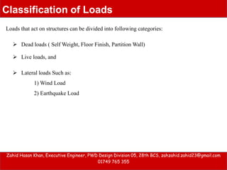
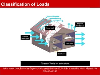
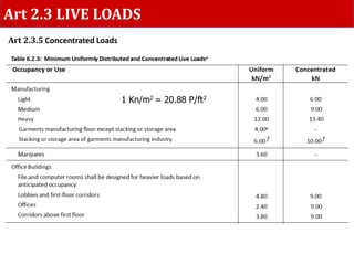
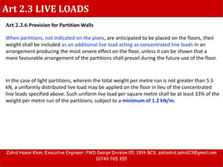
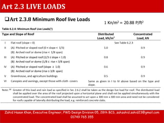
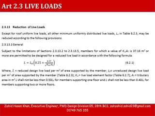
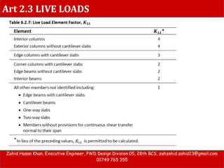
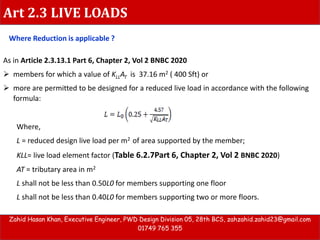
Vertical Load
Zahid Hasan Khan
Executive Engineer
PWD Design Division 05, 28th BCS
&
Deputy Project Manager, BSPP
zahid.zahid23@yahoo.com
01749 765 355
Loads that act on structures can be divided into following categories:
Zahid Hasan Khan, Executive Engineer, PWD Design Division 05, 28th BCS, zahzahid.zahid23@gmail.com
01749 765 355
Classification of Loads
 Lateral loads Such as:
1) Wind Load
2) Earthquake Load
 Dead loads ( Self Weight, Floor Finish, Partition Wall)
 Live loads, and
Zahid Hasan Khan, Executive Engineer, PWD Design Division 05, 28th BCS, zahzahid.zahid23@gmail.com
01749 765 355
Classification of Loads
 Dead loads are those that are constant in magnitude and fixed in location throughout the
lifetime of the structure.
 Usually the major part of the dead toad is the weight of the structure itself.
i. weight of the member itself,
ii. weight of all materials of construction incorporated into the building
iii. weight of permanent partitions,
iv. weight of fixed service equipment
v . net effect of pre stressing.
 For buildings finish floors, and plastered ceilings are usually included as dead loads, and an
allowance is made for suspended loads such as piping and lighting fixtures.
Zahid Hasan Khan, Executive Engineer, PWD Design Division 05, 28th BCS, zahzahid.zahid23@gmail.com
01749 765 355
Dead Load
Art 2.2 Dead Loads
Zahid Hasan Khan, Executive Engineer, PWD Design Division 05, 28th BCS, zahzahid.zahid23@gmail.com
01749 765 355
Weight of Materials ( Art 2.2.4 ) 1 Kn/m3 = 6.366 P/ft3
Zahid Hasan Khan, Executive Engineer, PWD Design Division 05, 28th BCS, zahzahid.zahid23@gmail.com
01749 765 355
DEAD LOADS
Slab Thickness 6” So, SW = 6/12 X γ con Ksf
Beam Size : 12” X18”
So, SW = (12X18) X γ con K/ft
144
Column Size : 12” X18”
Floor Height : 10’-0”
SW =(12X18)X γ con X10 Kip
144
 SW from Material Property
Zahid Hasan Khan, Executive Engineer, PWD Design Division 05, 28th BCS, zahzahid.zahid23@gmail.com
01749 765 355
Dead Load
Zahid Hasan Khan, Executive Engineer, PWD Design Division 05, 28th BCS, zahzahid.zahid23@gmail.com
01749 765 355
DEAD LOADS
 When partition walls are indicated on the plans, their weight shall be considered as
dead load acting as concentrated line loads in their actual positions on the floor.
 The loads due to anticipated partition walls, which are not indicated on the plans,
shall be treated as live loads and determined in accordance with Sec 2.3.6
 Art 2.2.5 Weight of Permanent Partitions
Weights of fixed service equipment and other permanent machinery, such as
 electrical feeders and other machinery,
 heating,
 ventilating and
 air-conditioning systems,
 lifts and escalators,
 plumbing stacks and risers etc.
 2.2.6 Weight of Fixed Service Equipment
Zahid Hasan Khan, Executive Engineer, PWD Design Division 05, 28th BCS, zahzahid.zahid23@gmail.com
01749 765 355
Dead Load
In evaluating the final dead loads on a structural member for design purposes,
allowances shall be made for additional loads resulting from the
(i) difference between the prescribed and the actual weights of the members
and construction materials;
(ii) inclusion of future installations;
(iii) changes in occupancy or use of buildings; and
(iv) inclusion of structural and non-structural members not covered in Sections
2.2.2 and 2.2.3.
2.2.7 Additional Loads
Zahid Hasan Khan, Executive Engineer, PWD Design Division 05, 28th BCS, zahzahid.zahid23@gmail.com
01749 765 355
Art 2.3 LIVE LOADS
Art 2.3.3 MINIMUM FLOOR LIVE LOADS
The minimum floor live loads shall be the greatest actual imposed loads resulting from
the intended use or occupancy of the floor, and shall not be less than the uniformly
distributed load patterns specified in Sec 2.3.4 or the concentrated loads specified in Sec
2.3.5 whichever produces the most critical effect. The live loads shall be assumed to act
vertically upon the area projected on a horizontal plane
Art 2.3.4 Uniformly Distributed Loads
The uniformly distributed live load shall not be less than the values listed in Table 6.2.3,
reduced as may be specified in Sec 2.3.13, applied uniformly over the entire area of the
floor, or any portion thereof to produce the most adverse effects in the member concerned
Art 2.3 LIVE LOADS
Zahid Hasan Khan, Executive Engineer, PWD Design Division 05, 28th BCS, zahzahid.zahid23@gmail.com
01749 765 355
1 Kn/m2 = 20.88 P/ft2
 Minimum Uniformly Distributed Load Art 2.3.4
Zahid Hasan Khan, Executive Engineer, PWD Design Division 05, 28th BCS, zahzahid.zahid23@gmail.com
01749 765 355
Example -1
 Architectural Plan
60 Psf
100 Psf
100 Psf
Zahid Hasan Khan, Executive Engineer, PWD Design Division 05, 28th BCS, zahzahid.zahid23@gmail.com
01749 765 355
Example -1
 Architectural Plan
100 Psf
40 Psf
40 Psf
40 Psf
100 Psf
40 Psf
Art 2.3 LIVE LOADS
1 Kn/m2 = 20.88 P/ft2
Art 2.3.5 Concentrated Loads
Art 2.3 LIVE LOADS
Art 2.3.6 Provision for Partition Walls
When partitions, not indicated on the plans, are anticipated to be placed on the floors, their
weight shall be included as an additional live load acting as concentrated line loads in an
arrangement producing the most severe effect on the floor, unless it can be shown that a
more favourable arrangement of the partitions shall prevail during the future use of the floor.
Zahid Hasan Khan, Executive Engineer, PWD Design Division 05, 28th BCS, zahzahid.zahid23@gmail.com
01749 765 355
In the case of light partitions, wherein the total weight per metre run is not greater than 5.5
kN, a uniformly distributed live load may be applied on the floor in lieu of the concentrated
line loads specified above. Such uniform live load per square metre shall be at least 33% of the
weight per metre run of the partitions, subject to a minimum of 1.2 kN/m2
Art 2.3 LIVE LOADS
1 Kn/m2 = 20.88 P/ft2
Zahid Hasan Khan, Executive Engineer, PWD Design Division 05, 28th BCS, zahzahid.zahid23@gmail.com
01749 765 355
Art 2.3.8 Minimum Roof live Loads
Art 2.3 LIVE LOADS
Zahid Hasan Khan, Executive Engineer, PWD Design Division 05, 28th BCS, zahzahid.zahid23@gmail.com
01749 765 355
Art 2.3 LIVE LOADS
Zahid Hasan Khan, Executive Engineer, PWD Design Division 05, 28th BCS, zahzahid.zahid23@gmail.com
01749 765 355
Art 2.3 LIVE LOADS
Zahid Hasan Khan, Executive Engineer, PWD Design Division 05, 28th BCS, zahzahid.zahid23@gmail.com
01749 765 355
Where Reduction is applicable ?
As in Article 2.3.13.1 Part 6, Chapter 2, Vol 2 BNBC 2020
 members for which a value of KLLAT is 37.16 m2 ( 400 Sft) or
 more are permitted to be designed for a reduced live load in accordance with the following
formula:
Where,
L = reduced design live load per m2 of area supported by the member;
KLL= live load element factor (Table 6.2.7Part 6, Chapter 2, Vol 2 BNBC 2020)
AT = tributary area in m2
L shall not be less than 0.50L0 for members supporting one floor
L shall not be less than 0.40L0 for members supporting two or more floors.
Art 2.3 LIVE LOADS
Zahid Hasan Khan, Executive Engineer, PWD Design Division 05, 28th BCS, zahzahid.zahid23@gmail.com
01749 765 355
Example Live Load
Art 2.3 LIVE LOADS
Zahid Hasan Khan, Executive Engineer, PWD Design Division 05, 28th BCS, zahzahid.zahid23@gmail.com
01749 765 355
 Example Live Load Reduction:
Building Information
 Building Location: Tangail
 No of Story: 8 stories
 Building Plinth Area: 2545 m2 (27387 ft2) ;
 Total Height of The Building: 29.25 m (96 ft)
 Use of The Building: Institutional
 Type of Structure: Moment Resisting Frame System without Shear wall.
Art 2.3 LIVE LOADS
Zahid Hasan Khan, Executive Engineer, PWD Design Division 05, 28th BCS, zahzahid.zahid23@gmail.com
01749 765 355
 Example Live Load Reduction:
Art 2.3 LIVE LOADS
Zahid Hasan Khan, Executive Engineer, PWD Design Division 05, 28th BCS, zahzahid.zahid23@gmail.com
01749 765 355
 Example Live Load Reduction:  Member Property: Slab = 5”, Beam =
10X18, GB = 10 X 18, Column = 12 X 18
 Dead & Live Loads:
SW = 62.5 Psf ,
Floor finish = 20 psf,
Brick Wall = 0.425 K/ft,
Live load = 40 psf,
Art 2.3 LIVE LOADS
Zahid Hasan Khan, Executive Engineer, PWD Design Division 05, 28th BCS, zahzahid.zahid23@gmail.com
01749 765 355
 Example Live Load Reduction:
Reduction of Live Loads
AT = 14’-0” X 14’-2” = 198.24 Sft = 18.42 m2 < 37.16 m2 .
So Reduction is need not be applied to 1st Floor.
The sum of tributary area at 2nd floor will be (18.42+18.42) = 36.84 m2 < 37.16 m2 .
So Reduction is need not be applied to 2nd Floor.
The sum of tributary area at 3rd floor will be (18.42+18.42+18.42) = 55.26 m2 > 37.16 m2 .
So Reduction will be applied to 3rd Floor.
Art 2.3 LIVE LOADS
Zahid Hasan Khan, Executive Engineer, PWD Design Division 05, 28th BCS, zahzahid.zahid23@gmail.com
01749 765 355
L = 31.41 Psf
= 78.24 % Lo Can be applied ( or 31.29 Psf)
So Reduction will be 21.76 %
At Ground Floor, 1st Floor Live Load is 40 Psf
At 2nd Floor 31.41 Psf
At 3rd & 4t Floor 31.41 PSf
At 5th Floor 24.57 Psf
Thank you very much

Verticle load analysis according to BNBC 2020

  • 1.
    Vertical Load Zahid HasanKhan Executive Engineer PWD Design Division 05, 28th BCS & Deputy Project Manager, BSPP zahid.zahid23@yahoo.com 01749 765 355
  • 2.
    Loads that acton structures can be divided into following categories: Zahid Hasan Khan, Executive Engineer, PWD Design Division 05, 28th BCS, zahzahid.zahid23@gmail.com 01749 765 355 Classification of Loads  Lateral loads Such as: 1) Wind Load 2) Earthquake Load  Dead loads ( Self Weight, Floor Finish, Partition Wall)  Live loads, and
  • 3.
    Zahid Hasan Khan,Executive Engineer, PWD Design Division 05, 28th BCS, zahzahid.zahid23@gmail.com 01749 765 355 Classification of Loads
  • 4.
     Dead loadsare those that are constant in magnitude and fixed in location throughout the lifetime of the structure.  Usually the major part of the dead toad is the weight of the structure itself. i. weight of the member itself, ii. weight of all materials of construction incorporated into the building iii. weight of permanent partitions, iv. weight of fixed service equipment v . net effect of pre stressing.  For buildings finish floors, and plastered ceilings are usually included as dead loads, and an allowance is made for suspended loads such as piping and lighting fixtures. Zahid Hasan Khan, Executive Engineer, PWD Design Division 05, 28th BCS, zahzahid.zahid23@gmail.com 01749 765 355 Dead Load Art 2.2 Dead Loads
  • 5.
    Zahid Hasan Khan,Executive Engineer, PWD Design Division 05, 28th BCS, zahzahid.zahid23@gmail.com 01749 765 355 Weight of Materials ( Art 2.2.4 ) 1 Kn/m3 = 6.366 P/ft3
  • 6.
    Zahid Hasan Khan,Executive Engineer, PWD Design Division 05, 28th BCS, zahzahid.zahid23@gmail.com 01749 765 355 DEAD LOADS Slab Thickness 6” So, SW = 6/12 X γ con Ksf Beam Size : 12” X18” So, SW = (12X18) X γ con K/ft 144 Column Size : 12” X18” Floor Height : 10’-0” SW =(12X18)X γ con X10 Kip 144  SW from Material Property
  • 7.
    Zahid Hasan Khan,Executive Engineer, PWD Design Division 05, 28th BCS, zahzahid.zahid23@gmail.com 01749 765 355 Dead Load
  • 8.
    Zahid Hasan Khan,Executive Engineer, PWD Design Division 05, 28th BCS, zahzahid.zahid23@gmail.com 01749 765 355 DEAD LOADS  When partition walls are indicated on the plans, their weight shall be considered as dead load acting as concentrated line loads in their actual positions on the floor.  The loads due to anticipated partition walls, which are not indicated on the plans, shall be treated as live loads and determined in accordance with Sec 2.3.6  Art 2.2.5 Weight of Permanent Partitions Weights of fixed service equipment and other permanent machinery, such as  electrical feeders and other machinery,  heating,  ventilating and  air-conditioning systems,  lifts and escalators,  plumbing stacks and risers etc.  2.2.6 Weight of Fixed Service Equipment
  • 9.
    Zahid Hasan Khan,Executive Engineer, PWD Design Division 05, 28th BCS, zahzahid.zahid23@gmail.com 01749 765 355 Dead Load In evaluating the final dead loads on a structural member for design purposes, allowances shall be made for additional loads resulting from the (i) difference between the prescribed and the actual weights of the members and construction materials; (ii) inclusion of future installations; (iii) changes in occupancy or use of buildings; and (iv) inclusion of structural and non-structural members not covered in Sections 2.2.2 and 2.2.3. 2.2.7 Additional Loads
  • 10.
    Zahid Hasan Khan,Executive Engineer, PWD Design Division 05, 28th BCS, zahzahid.zahid23@gmail.com 01749 765 355 Art 2.3 LIVE LOADS Art 2.3.3 MINIMUM FLOOR LIVE LOADS The minimum floor live loads shall be the greatest actual imposed loads resulting from the intended use or occupancy of the floor, and shall not be less than the uniformly distributed load patterns specified in Sec 2.3.4 or the concentrated loads specified in Sec 2.3.5 whichever produces the most critical effect. The live loads shall be assumed to act vertically upon the area projected on a horizontal plane Art 2.3.4 Uniformly Distributed Loads The uniformly distributed live load shall not be less than the values listed in Table 6.2.3, reduced as may be specified in Sec 2.3.13, applied uniformly over the entire area of the floor, or any portion thereof to produce the most adverse effects in the member concerned
  • 11.
    Art 2.3 LIVELOADS Zahid Hasan Khan, Executive Engineer, PWD Design Division 05, 28th BCS, zahzahid.zahid23@gmail.com 01749 765 355 1 Kn/m2 = 20.88 P/ft2  Minimum Uniformly Distributed Load Art 2.3.4
  • 12.
    Zahid Hasan Khan,Executive Engineer, PWD Design Division 05, 28th BCS, zahzahid.zahid23@gmail.com 01749 765 355 Example -1  Architectural Plan 60 Psf 100 Psf 100 Psf
  • 13.
    Zahid Hasan Khan,Executive Engineer, PWD Design Division 05, 28th BCS, zahzahid.zahid23@gmail.com 01749 765 355 Example -1  Architectural Plan 100 Psf 40 Psf 40 Psf 40 Psf 100 Psf 40 Psf
  • 14.
    Art 2.3 LIVELOADS 1 Kn/m2 = 20.88 P/ft2 Art 2.3.5 Concentrated Loads
  • 15.
    Art 2.3 LIVELOADS Art 2.3.6 Provision for Partition Walls When partitions, not indicated on the plans, are anticipated to be placed on the floors, their weight shall be included as an additional live load acting as concentrated line loads in an arrangement producing the most severe effect on the floor, unless it can be shown that a more favourable arrangement of the partitions shall prevail during the future use of the floor. Zahid Hasan Khan, Executive Engineer, PWD Design Division 05, 28th BCS, zahzahid.zahid23@gmail.com 01749 765 355 In the case of light partitions, wherein the total weight per metre run is not greater than 5.5 kN, a uniformly distributed live load may be applied on the floor in lieu of the concentrated line loads specified above. Such uniform live load per square metre shall be at least 33% of the weight per metre run of the partitions, subject to a minimum of 1.2 kN/m2
  • 16.
    Art 2.3 LIVELOADS 1 Kn/m2 = 20.88 P/ft2 Zahid Hasan Khan, Executive Engineer, PWD Design Division 05, 28th BCS, zahzahid.zahid23@gmail.com 01749 765 355 Art 2.3.8 Minimum Roof live Loads
  • 17.
    Art 2.3 LIVELOADS Zahid Hasan Khan, Executive Engineer, PWD Design Division 05, 28th BCS, zahzahid.zahid23@gmail.com 01749 765 355
  • 18.
    Art 2.3 LIVELOADS Zahid Hasan Khan, Executive Engineer, PWD Design Division 05, 28th BCS, zahzahid.zahid23@gmail.com 01749 765 355
  • 19.
    Art 2.3 LIVELOADS Zahid Hasan Khan, Executive Engineer, PWD Design Division 05, 28th BCS, zahzahid.zahid23@gmail.com 01749 765 355 Where Reduction is applicable ? As in Article 2.3.13.1 Part 6, Chapter 2, Vol 2 BNBC 2020  members for which a value of KLLAT is 37.16 m2 ( 400 Sft) or  more are permitted to be designed for a reduced live load in accordance with the following formula: Where, L = reduced design live load per m2 of area supported by the member; KLL= live load element factor (Table 6.2.7Part 6, Chapter 2, Vol 2 BNBC 2020) AT = tributary area in m2 L shall not be less than 0.50L0 for members supporting one floor L shall not be less than 0.40L0 for members supporting two or more floors.
  • 20.
    Art 2.3 LIVELOADS Zahid Hasan Khan, Executive Engineer, PWD Design Division 05, 28th BCS, zahzahid.zahid23@gmail.com 01749 765 355 Example Live Load
  • 21.
    Art 2.3 LIVELOADS Zahid Hasan Khan, Executive Engineer, PWD Design Division 05, 28th BCS, zahzahid.zahid23@gmail.com 01749 765 355  Example Live Load Reduction: Building Information  Building Location: Tangail  No of Story: 8 stories  Building Plinth Area: 2545 m2 (27387 ft2) ;  Total Height of The Building: 29.25 m (96 ft)  Use of The Building: Institutional  Type of Structure: Moment Resisting Frame System without Shear wall.
  • 22.
    Art 2.3 LIVELOADS Zahid Hasan Khan, Executive Engineer, PWD Design Division 05, 28th BCS, zahzahid.zahid23@gmail.com 01749 765 355  Example Live Load Reduction:
  • 23.
    Art 2.3 LIVELOADS Zahid Hasan Khan, Executive Engineer, PWD Design Division 05, 28th BCS, zahzahid.zahid23@gmail.com 01749 765 355  Example Live Load Reduction:  Member Property: Slab = 5”, Beam = 10X18, GB = 10 X 18, Column = 12 X 18  Dead & Live Loads: SW = 62.5 Psf , Floor finish = 20 psf, Brick Wall = 0.425 K/ft, Live load = 40 psf,
  • 24.
    Art 2.3 LIVELOADS Zahid Hasan Khan, Executive Engineer, PWD Design Division 05, 28th BCS, zahzahid.zahid23@gmail.com 01749 765 355  Example Live Load Reduction: Reduction of Live Loads AT = 14’-0” X 14’-2” = 198.24 Sft = 18.42 m2 < 37.16 m2 . So Reduction is need not be applied to 1st Floor. The sum of tributary area at 2nd floor will be (18.42+18.42) = 36.84 m2 < 37.16 m2 . So Reduction is need not be applied to 2nd Floor. The sum of tributary area at 3rd floor will be (18.42+18.42+18.42) = 55.26 m2 > 37.16 m2 . So Reduction will be applied to 3rd Floor.
  • 25.
    Art 2.3 LIVELOADS Zahid Hasan Khan, Executive Engineer, PWD Design Division 05, 28th BCS, zahzahid.zahid23@gmail.com 01749 765 355 L = 31.41 Psf = 78.24 % Lo Can be applied ( or 31.29 Psf) So Reduction will be 21.76 % At Ground Floor, 1st Floor Live Load is 40 Psf At 2nd Floor 31.41 Psf At 3rd & 4t Floor 31.41 PSf At 5th Floor 24.57 Psf
  • 26.