SlideShare a Scribd company logo
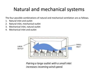
Natural and mechanical systems
The four possible combinations of natural and mechanical ventilation are as follows.
1. Natural inlet and outlet
2. Natural inlet, mechanical outlet
3. Mechanical inlet, natural outlet
4. Mechanical inlet and outlet
Figure 6
Figure 6 shows typical sources of heat and moisture, which are commonly
called cooling loads:
Figure 6 shows typical sources of heat and moisture, which are commonly
called cooling loads:
• Conduction heat gain from outdoors through the roof, exterior walls, and glass windows
or skylights.
• Solar radiation heat gain through glass windows or skylights. Conduction heat gain
through the ceiling, interior partition walls, and the floor.
• Internal heat and moisture generated by people, lights, appliances, and equipment in
the space.
• Heat gain from air infiltrating into the space from outdoors.
• In addition to those depicted on Figure 6, other common sources of heat and
moisture include:
• Heat gain from outdoor air deliberately brought into the building for ventilation
purposes.
• Heat generated by the fans and motors in the system.
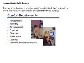
Introduction to HVAC Systems
The goal of the heating, ventilating, and air conditioning (HVAC) system is to
create and maintain a comfortable environment within a building.
A damper is a valve or plate that stops or regulates the flow of air inside
a duct, chimney, VAV box, air handler, or other air-handling equipment
Heating
Heating is performed by low- or high-pressure hot-water
finned pipe heater battery, electric resistance heater or
fuel-fired heat exchanger .
Cooling
Cooling is performed by pumping chilled water, brine or
refrigerant through a finned pipe battery. When the
coolant temperature is below the air dew-point,
condensation occurs, and the air will be dehumidified.
Mixing
Mixing of two airstreams occurs when the fresh-air intake
joins the recirculated room air. The quantity of each air
stream is regulated by multileaf dampers operated by
electric motors under the direction of an automatic control
system.
Humidification In winter, incoming fresh air
with a low moisture content can be humidified
by steam injection, banks of water sprays,
evaporation from a heated water tank, a
spinning disc atomizer or a soaked porous
plastic sponge.
A variable air volume (VAV) system has either
an air volume control damper or a centrifugal
fan in the terminal unit to control the quantity
of air flowing into the room in response to
signals from a room air temperature sensor.
The single-duct system (Fig. 5.10) is used for a
large room such as an atrium, a banking hall, a
swimming pool, or a lecture, entertainment or
operating theatre. It can be applied to groups
of rooms with a similar demand for air
conditioning, such as offices facing the same
side of the building.
period one
Dissecting HVAC Systems
• while these five loops can be used to describe virtually any HVAC system, not
every system uses all five loops.
• while another loop could be added for heating and humidifying the space in
some systems, this clinic focuses primarily on comfort cooling, not heating.
• The purpose is to understand the components of different types of HVAC systems.
• The premise of this method is that any HVAC system can be dissected into basic
subsystems.
• These subsystems will be referred to as “loops.”
• There are five primary loops that can describe virtually any type of HVAC system.
Airside Loop
• The first loop is the airside loop, and the first component of this loop is the conditioned
space.
• The first two comfort requirements mentioned were temperature and humidity.
• In order to maintain the
dry-bulb temperature in
the conditioned space,
heat (referred to as
sensible heat) must be
added or removed at the
same rate as it leaves or
enters the space.
• In order to maintain the
humidity level in the space,
moisture (sometimes
referred to as latent heat)
must be added or removed
at the same rate as it
leaves or enters the space.
supply air:
Most HVAC systems used today deliver conditioned (heated, cooled,
humidified, or dehumidified) air to the conditioned space to add or remove
sensible heat and moisture. This conditioned air is called supply air.
return air:
The air that carries the heat and moisture out of the space is called return air.
Imagine the conditioned supply air as a sponge. In the cooling mode, as it
enters a space, this “sponge” (supply air) absorbs sensible heat and moisture.
The amount of sensible heat and moisture absorbed depends on the
temperature and humidity, as well as the quantity, of the supply air. Assuming a
fixed quantity of air, if the supply air is colder, it can remove more sensible heat
from the space. If the supply air is drier, it can remove more moisture from the
space.
• supply fan: The next component of the airside loop is a supply fan that delivers the
supply air (SA) to the space.
• return fan: This same supply fan is often used to also draw the return air out of the
space. Alternatively, some systems use a second fan, called a return fan, to draw air
from the space and move it back to the equipment that contains the supply fan.
• Filter: The air must also be filtered. In a typical HVAC system, the mixed air passes
through a filter to remove many of the airborne contaminants.
Outdoor air (OA)
return air (RA)
exhaust air (EA)
mixed air (MA)
cooling coil: As mentioned earlier, during the cooling mode, the supply air must be cold
enough to absorb excess sensible heat from the space and dry enough to
absorb excess moisture (latent heat). A heat exchanger, commonly known as a
cooling coil, is often used to cool and dehumidify the supply air before it is
delivered to the space.
A typical cooling coil includes rows of tubes passing through sheets of formed
fins. A cold fluid, either water or liquid refrigerant, enters one header at the end
of the coil and then flows through the tubes, cooling both the tubes and the
fins.
Figure 8
Figure 9
Figure 9 shows an example of a cooling coil that has chilled water flowing
through it. As the warm, humid mixed air passes through the coil, it comes into
contact with the cold tubes and fins. Sensible heat is transferred from the air to
the fluid inside the tubes, causing the air to be cooled.
Additionally, if the outside surface temperature of the tubes and fins is below
the dew-point temperature of the entering air, moisture contained in the air will
condense on the tubes and fins. This condensed liquid then flows down the fin
surfaces into a drain pan located underneath the coil, and is piped away. The air
(supply air) leaving the coil is colder and drier than when it entered.
Many HVAC systems also use the airside loop for heating and humidification.
Often, a heating coil or humidifier is located near the cooling coil in the same
airside loop. Alternatively, a heating coil or humidifier may be part of a second,
separate airside loop. Assuming a fixed quantity of air, if the supply air is
warmer, it can add more sensible heat to the space. If the supply air is more
humid, it can add more moisture to the space. For simplicity, however, this
period focuses primarily on comfort cooling.
Figure 10
The airside loop responds to changing cooling loads in the
conditioned space by varying either
• the temperature or
• the quantity of air delivered to the space.
A constant-volume system provides a constant quantity of supply
air and varies the supply-air temperature in response to the
changing cooling load in the space.
A variable-air-volume (VAV) system varies the quantity of constant temperature
supply air in response to the changing cooling load in the space.
In this system, a VAV terminal unit is added to the airside loop.
Figure 11
A supply-air distribution system, typically constructed of sheet-metal ducts,
fittings, and diffusers, is used to direct the supply air from the central air
handler to one or more conditioned spaces. The example airside loop in
Figure 14 includes a central air handler and ductwork to deliver supply air to
multiple VAV terminal units.
From each VAV terminal unit, the supply air travels through a section of flexible
duct to remotely located diffusers. Diffusers are used to distribute the supply
air effectively to the conditioned space. Proper air diffusion is an important
comfort consideration, especially in VAV systems, to avoid dumping cold
supply air on the occupants of the space.
Figure 14
In Figure 15, air returns from the conditioned space to the central air handler
through an open ceiling plenum. The plenum is the space between the ceiling
and the roof, or floor, above.
Alternatively, a separate return-air duct system could be used to direct the
return air back to the air handler.
Figure 15
Chilled-Water Loop
HVAC
Chilled-Water Loop
In the airside loop, a cooling coil is used to cool and dehumidify the supply
air. As mentioned, the cold fluid flowing through the tubes of the coil may be
either water or liquid refrigerant. Systems that use water flowing through the
cooling coil also contain a chilled-water loop.
Heat energy flows from a higher-temperature substance to a lower-temperature
substance. Therefore, in order for heat to be transferred from the air, the fluid flowing
through the tubes of the cooling coil must be colder than the air passing over the tubes and
fins.
It has also been mentioned that the water flowing through the cooling coil must
be colder than the air passing through it. A heat exchanger is used to cool the
water that returns from the coil. This heat exchanger, called an evaporator, is
one component of the refrigeration (cooling) equipment.
Figure 18 shows a shell-and-tube evaporator that has cold liquid refrigerant
flowing through the tubes. Warm water enters at one end of the shell and fills
the space surrounding the tubes. Heat is transferred from the water to the refrigerant inside
the tubes, and chilled water leaves from the opposite end of
the shell.
Figure 18
The third component of the chilled-water loop is a pump that moves water
around the loop. This pump needs to have enough power to move the water
through the piping, the evaporator, the tubes of the coil, and any other
accessories installed in the chilled-water loop.
Similar to the airside loop, the chilled-water loop responds to changing cooling
loads by varying either the temperature or the quantity of water delivered to the
cooling coil. The most common method, however, is to vary the quantity of
water flowing through the cooling coil by using a control valve. As the cooling
load decreases, the modulating control valve reduces the rate of chilled-water
flow through the coil, decreasing its cooling capacity.
Figure 19
Notice that the control valve is located at the
outlet, or downstream, of the
cooling coil. This location ensures that the
tubes inside the coil are always full
of water. A valve located at the inlet, or
upstream, of the coil may modulate to
the point where the water just “trickles”
through the tubes, not filling the entire
tube diameter. The result is unpredictable heat
transfer and less-stable control.
Refrigeration Loop
HVAC
Refrigeration Loop
The third loop is the refrigeration loop. Recall that in the chilled-water loop, the
evaporator allows heat to transfer from the water to cold liquid refrigerant. As heat is
transferred from the water to the refrigerant, the liquid refrigerant boils. The resulting
refrigerant vapor is further warmed inside the evaporator before being drawn to the
compressor.
The compressor is used
to pump the low-
pressure refrigerant
vapor from the
evaporator and compress
it to a higher pressure.
This increase in pressure
also raises the
temperature of the
refrigerant vapor.
After being discharged from the compressor, the hot, high-pressure refrigerant
vapor enters a condenser. The condenser is a heat exchanger that transfers
heat from the hot refrigerant vapor to air, water, or some other fluid that is at a
colder temperature. As heat is removed from the refrigerant, it condenses and
returns to the liquid phase.
Figure 24
The condenser shown in Figure 24 is a water-cooled condenser that transfers
heat from the refrigerant to a separate condenser-water loop.
The three most common types of condensers are air-cooled, evaporative, and
water-cooled. A typical air-cooled condenser has the hot, high-pressure
refrigerant vapor flowing through the tubes of a finned-tube heat exchanger
and uses propeller-type fans to draw outdoor air over the outer surfaces of the
tubes and fins.
Figure 25
A variation of the air-cooled condenser is the evaporative condenser. Within
this device, the refrigerant flows through tubes and air is drawn or blown over
the tubes by a fan. The difference is that water is sprayed on the outer surfaces
of the tubes. As the air passes over the tubes, it causes a small portion of the
water to evaporate. This evaporation process improves the heat transfer from
the condensing refrigerant. The remaining water then falls into the sump to be
recirculated by a small pump and used again.
The most common type of water-cooled condenser is the shell-and-tube
design. With this design, water flows through the tubes while the hot
refrigerant vapor fills the space surrounding the tubes. As heat is transferred
from the refrigerant to the water, the refrigerant vapor condenses on the outer
surfaces of the tubes and the condensed liquid refrigerant falls to the bottom of
the shell.
The liquid refrigerant that leaves the condenser is still at a relatively high
temperature. The final step of the refrigeration cycle is for this hot liquid refrigerant to
pass through anexpansion device.
This device creates a large pressure drop that reduces the
pressure, and correspondingly the temperature, of the refrigerant, where it is
again cold enough to absorb heat inside the evaporator. There are several types
of expansion devices, but the one shown in this example is a thermostatic
expansion valve (TXV).
Figure 26
In this arrangement, the chilled-water loop does not exist. Heat is transferred
from the airside loop directly to the refrigeration loop.
Figure 29
Heat-Rejection Loop
HVAC
Heat-Rejection Loop
The fourth loop is the heat-rejection loop. In the refrigeration loop, the
condenser transfers heat from the hot refrigerant to air, water, or some other
fluid. water enters the condenser , absorbs heat from the hot
refrigerant, and leaves.
The water flowing through the condenser must be colder than the hot
refrigerant vapor. A heat exchanger is required to cool the water that returns
from the condenser, back to the desired temperature, before it is pumped back to the
condenser. When a water-cooled condenser is used, this heat exchanger is typically either a
cooling tower or a fluid cooler (also known as a dry cooler).
Figure 31
In a cooling tower, the warm water returning from the condenser is sprayed
over the fill inside the tower while a propeller fan draws outdoor air upward
through the fill. One common type of fill consists of several thin, closely spaced
layers of plastic or wood. The water spreads over the surface of the fill to
increase the contact with the passing air. The movement of air through the fill
allows heat to transfer from the water to the air. This causes some of the water
to evaporate, a process that cools the remaining water. The remaining cooled
water then falls to the tower sump and is returned to the condenser.
Figure 32
The third component of the heat-rejection loop moves the condensing media
(water in this example) around the loop. In the case of a water cooled
condenser, a pump is needed to move the water through the tubes of
the condenser, the piping, the cooling tower, and any other accessories
installed in the heat-rejection loop.
The heat-rejection capacity of this loop can be varied in response to changing
heat-rejection requirements. In the case of a water-cooled condenser, this is
commonly accomplished by varying the temperature of water delivered to the
condenser. Varying the temperature of the entering condenser water may be
accomplished by using variable-speed fans in the cooling tower or by cycling
the fans on and off.
Figure 33
One method of varying the quantity of water flowing through the water-cooled
condenser is to use a modulating control valve. As the heat-rejection
requirement decreases, the modulating control valve directs less water through
the condenser.
A second example (Figure 35) of the heat-rejection loop is a packaged, air cooled
chiller. It combines all the components of the refrigeration and heat rejection
loops.
When CFCs are released into the atmosphere as a result of leakage from refrigeration
systems, the production of expanded foam, venting to the atmosphere during maintenance
of refrigeration compressors, the use of aerosols, chemical cleaning or the destruction of
refrigerators, they find their way to the upper atmosphere, where they are broken down by
the action of ultraviolet solar radiation and chlorine is released. This degradation will
continue for many years. Atmospheric ozone is destroyed by the chlorine, and it is reported
that the resulting increase in the levels of ultraviolet radiation reaching the earth’s surface
will cause ecological damage as well as an increase in skin cancer.
VENTILATION.pptx

More Related Content

Similar to VENTILATION.pptx

Fundamentals of hvac controls
Fundamentals of hvac controlsFundamentals of hvac controls
Fundamentals of hvac controls
Serenity Dawn
 
HVAC
HVACHVAC
Air Conditioner Work Process
Air Conditioner Work ProcessAir Conditioner Work Process
Air Conditioner Work Process
Sanjay Jetley
 
Air Conditioning and Security Installations
Air Conditioning and Security InstallationsAir Conditioning and Security Installations
Air Conditioning and Security Installations
Kalokwera Samuel
 
HVAC
HVACHVAC
HVAC FOR ENERGY EFFICIENT BUILDING
HVAC FOR ENERGY EFFICIENT BUILDINGHVAC FOR ENERGY EFFICIENT BUILDING
HVAC FOR ENERGY EFFICIENT BUILDING
Harsha Singh
 
hvac systems basic components
hvac systems basic componentshvac systems basic components
hvac systems basic components
WEGIGASIM1
 
hvac-systems-components 2023.ppt
hvac-systems-components 2023.ppthvac-systems-components 2023.ppt
hvac-systems-components 2023.ppt
ssuserc4ad1a1
 
Hvac systems-components
Hvac systems-componentsHvac systems-components
Hvac systems-components
Amit Kumar
 
hvac-systems-components.ppt
hvac-systems-components.ppthvac-systems-components.ppt
hvac-systems-components.ppt
SharanabasappaDegoan
 
HVAC
HVACHVAC
HVAC
sania2014
 
Engineering plant facilities 01 concepts formulas and uom
Engineering plant facilities 01 concepts  formulas and uomEngineering plant facilities 01 concepts  formulas and uom
Engineering plant facilities 01 concepts formulas and uom
Luis Cabrera
 
Air conditioning system
Air conditioning systemAir conditioning system
Air conditioning system
Devesh Tripathi
 
Refrigeration system
Refrigeration system Refrigeration system
Refrigeration system
Sagar Joshi
 
Air Conditioner Work Process
Air Conditioner Work ProcessAir Conditioner Work Process
Air Conditioner Work Process
Sanjay Jetley
 
Water Chilled Airconditioning
Water Chilled AirconditioningWater Chilled Airconditioning
Water Chilled Airconditioning
Aljon Altiche
 
Air handling sysytem
Air handling sysytemAir handling sysytem
Air handling sysytem
purnimatunuguntla
 
ventilation in building
ventilation in buildingventilation in building
ventilation in building
Chitra Rana
 
Hvac
HvacHvac
process design of water chilling plant
process design of water chilling plantprocess design of water chilling plant
process design of water chilling plant
Dinesh Sannepally
 

Similar to VENTILATION.pptx (20)

Fundamentals of hvac controls
Fundamentals of hvac controlsFundamentals of hvac controls
Fundamentals of hvac controls
 
HVAC
HVACHVAC
HVAC
 
Air Conditioner Work Process
Air Conditioner Work ProcessAir Conditioner Work Process
Air Conditioner Work Process
 
Air Conditioning and Security Installations
Air Conditioning and Security InstallationsAir Conditioning and Security Installations
Air Conditioning and Security Installations
 
HVAC
HVACHVAC
HVAC
 
HVAC FOR ENERGY EFFICIENT BUILDING
HVAC FOR ENERGY EFFICIENT BUILDINGHVAC FOR ENERGY EFFICIENT BUILDING
HVAC FOR ENERGY EFFICIENT BUILDING
 
hvac systems basic components
hvac systems basic componentshvac systems basic components
hvac systems basic components
 
hvac-systems-components 2023.ppt
hvac-systems-components 2023.ppthvac-systems-components 2023.ppt
hvac-systems-components 2023.ppt
 
Hvac systems-components
Hvac systems-componentsHvac systems-components
Hvac systems-components
 
hvac-systems-components.ppt
hvac-systems-components.ppthvac-systems-components.ppt
hvac-systems-components.ppt
 
HVAC
HVACHVAC
HVAC
 
Engineering plant facilities 01 concepts formulas and uom
Engineering plant facilities 01 concepts  formulas and uomEngineering plant facilities 01 concepts  formulas and uom
Engineering plant facilities 01 concepts formulas and uom
 
Air conditioning system
Air conditioning systemAir conditioning system
Air conditioning system
 
Refrigeration system
Refrigeration system Refrigeration system
Refrigeration system
 
Air Conditioner Work Process
Air Conditioner Work ProcessAir Conditioner Work Process
Air Conditioner Work Process
 
Water Chilled Airconditioning
Water Chilled AirconditioningWater Chilled Airconditioning
Water Chilled Airconditioning
 
Air handling sysytem
Air handling sysytemAir handling sysytem
Air handling sysytem
 
ventilation in building
ventilation in buildingventilation in building
ventilation in building
 
Hvac
HvacHvac
Hvac
 
process design of water chilling plant
process design of water chilling plantprocess design of water chilling plant
process design of water chilling plant
 

More from Kashif390970

insulation Material,QUIet bAtt 30°.pptx
insulation Material,QUIet bAtt 30°.pptxinsulation Material,QUIet bAtt 30°.pptx
insulation Material,QUIet bAtt 30°.pptx
Kashif390970
 
ottoMan empire.pdf
ottoMan empire.pdfottoMan empire.pdf
ottoMan empire.pdf
Kashif390970
 
ELEMENTS OF ARCHITECTURE.pptx
ELEMENTS OF ARCHITECTURE.pptxELEMENTS OF ARCHITECTURE.pptx
ELEMENTS OF ARCHITECTURE.pptx
Kashif390970
 
HOTEL Categories.pptx
HOTEL Categories.pptxHOTEL Categories.pptx
HOTEL Categories.pptx
Kashif390970
 
Architectural acoustics.pptx
Architectural acoustics.pptxArchitectural acoustics.pptx
Architectural acoustics.pptx
Kashif390970
 
Problems faced by building by moisture or precipitation.pptx
Problems faced by building by moisture or precipitation.pptxProblems faced by building by moisture or precipitation.pptx
Problems faced by building by moisture or precipitation.pptx
Kashif390970
 
HOTEL Categories.pptx
HOTEL Categories.pptxHOTEL Categories.pptx
HOTEL Categories.pptx
Kashif390970
 
CLIMATE RESPONSIVE Design Features.pptx
CLIMATE RESPONSIVE  Design Features.pptxCLIMATE RESPONSIVE  Design Features.pptx
CLIMATE RESPONSIVE Design Features.pptx
Kashif390970
 
ARTIST RESIDENCY.pptx
ARTIST RESIDENCY.pptxARTIST RESIDENCY.pptx
ARTIST RESIDENCY.pptx
Kashif390970
 
KENDEDA BUILDING.pptx
KENDEDA BUILDING.pptxKENDEDA BUILDING.pptx
KENDEDA BUILDING.pptx
Kashif390970
 
TIDAL PARK CHINNAI , INDIA.pptx
TIDAL PARK CHINNAI , INDIA.pptxTIDAL PARK CHINNAI , INDIA.pptx
TIDAL PARK CHINNAI , INDIA.pptx
Kashif390970
 
peerak case study.pptx
peerak case study.pptxpeerak case study.pptx
peerak case study.pptx
Kashif390970
 
smart building.pptx
smart building.pptxsmart building.pptx
smart building.pptx
Kashif390970
 
WATER HARVESTING PROCESS.pptx
WATER HARVESTING PROCESS.pptxWATER HARVESTING PROCESS.pptx
WATER HARVESTING PROCESS.pptx
Kashif390970
 
surface finishes MATERIAL.pptx
surface finishes MATERIAL.pptxsurface finishes MATERIAL.pptx
surface finishes MATERIAL.pptx
Kashif390970
 
FRAME STRUCTURE.pptx
FRAME STRUCTURE.pptxFRAME STRUCTURE.pptx
FRAME STRUCTURE.pptx
Kashif390970
 

More from Kashif390970 (16)

insulation Material,QUIet bAtt 30°.pptx
insulation Material,QUIet bAtt 30°.pptxinsulation Material,QUIet bAtt 30°.pptx
insulation Material,QUIet bAtt 30°.pptx
 
ottoMan empire.pdf
ottoMan empire.pdfottoMan empire.pdf
ottoMan empire.pdf
 
ELEMENTS OF ARCHITECTURE.pptx
ELEMENTS OF ARCHITECTURE.pptxELEMENTS OF ARCHITECTURE.pptx
ELEMENTS OF ARCHITECTURE.pptx
 
HOTEL Categories.pptx
HOTEL Categories.pptxHOTEL Categories.pptx
HOTEL Categories.pptx
 
Architectural acoustics.pptx
Architectural acoustics.pptxArchitectural acoustics.pptx
Architectural acoustics.pptx
 
Problems faced by building by moisture or precipitation.pptx
Problems faced by building by moisture or precipitation.pptxProblems faced by building by moisture or precipitation.pptx
Problems faced by building by moisture or precipitation.pptx
 
HOTEL Categories.pptx
HOTEL Categories.pptxHOTEL Categories.pptx
HOTEL Categories.pptx
 
CLIMATE RESPONSIVE Design Features.pptx
CLIMATE RESPONSIVE  Design Features.pptxCLIMATE RESPONSIVE  Design Features.pptx
CLIMATE RESPONSIVE Design Features.pptx
 
ARTIST RESIDENCY.pptx
ARTIST RESIDENCY.pptxARTIST RESIDENCY.pptx
ARTIST RESIDENCY.pptx
 
KENDEDA BUILDING.pptx
KENDEDA BUILDING.pptxKENDEDA BUILDING.pptx
KENDEDA BUILDING.pptx
 
TIDAL PARK CHINNAI , INDIA.pptx
TIDAL PARK CHINNAI , INDIA.pptxTIDAL PARK CHINNAI , INDIA.pptx
TIDAL PARK CHINNAI , INDIA.pptx
 
peerak case study.pptx
peerak case study.pptxpeerak case study.pptx
peerak case study.pptx
 
smart building.pptx
smart building.pptxsmart building.pptx
smart building.pptx
 
WATER HARVESTING PROCESS.pptx
WATER HARVESTING PROCESS.pptxWATER HARVESTING PROCESS.pptx
WATER HARVESTING PROCESS.pptx
 
surface finishes MATERIAL.pptx
surface finishes MATERIAL.pptxsurface finishes MATERIAL.pptx
surface finishes MATERIAL.pptx
 
FRAME STRUCTURE.pptx
FRAME STRUCTURE.pptxFRAME STRUCTURE.pptx
FRAME STRUCTURE.pptx
 

Recently uploaded

Impact of Fonts: in Web and Apps Design
Impact of Fonts:  in Web and Apps DesignImpact of Fonts:  in Web and Apps Design
Impact of Fonts: in Web and Apps Design
contactproperweb2014
 
一比一原版(Columbia毕业证)哥伦比亚大学毕业证如何办理
一比一原版(Columbia毕业证)哥伦比亚大学毕业证如何办理一比一原版(Columbia毕业证)哥伦比亚大学毕业证如何办理
一比一原版(Columbia毕业证)哥伦比亚大学毕业证如何办理
asuzyq
 
ARENA - Young adults in the workplace (Knight Moves).pdf
ARENA - Young adults in the workplace (Knight Moves).pdfARENA - Young adults in the workplace (Knight Moves).pdf
ARENA - Young adults in the workplace (Knight Moves).pdf
Knight Moves
 
EASY TUTORIAL OF HOW TO USE CAPCUT BY: FEBLESS HERNANE
EASY TUTORIAL OF HOW TO USE CAPCUT BY: FEBLESS HERNANEEASY TUTORIAL OF HOW TO USE CAPCUT BY: FEBLESS HERNANE
EASY TUTORIAL OF HOW TO USE CAPCUT BY: FEBLESS HERNANE
Febless Hernane
 
NHR Engineers Portfolio 2023 2024 NISHANT RATHI
NHR Engineers Portfolio 2023 2024 NISHANT RATHINHR Engineers Portfolio 2023 2024 NISHANT RATHI
NHR Engineers Portfolio 2023 2024 NISHANT RATHI
NishantRathi18
 
Top Interior Designers in Bangalore.pdf1
Top Interior Designers in Bangalore.pdf1Top Interior Designers in Bangalore.pdf1
Top Interior Designers in Bangalore.pdf1
Decomart Studio
 
UNIT V ACTIONS AND COMMANDS, FORMS AND CONTROLS.pptx
UNIT V ACTIONS AND COMMANDS, FORMS AND CONTROLS.pptxUNIT V ACTIONS AND COMMANDS, FORMS AND CONTROLS.pptx
UNIT V ACTIONS AND COMMANDS, FORMS AND CONTROLS.pptx
GOWSIKRAJA PALANISAMY
 
定制美国西雅图城市大学毕业证学历证书原版一模一样
定制美国西雅图城市大学毕业证学历证书原版一模一样定制美国西雅图城市大学毕业证学历证书原版一模一样
定制美国西雅图城市大学毕业证学历证书原版一模一样
qo1as76n
 
一比一原版(UW毕业证)西雅图华盛顿大学毕业证如何办理
一比一原版(UW毕业证)西雅图华盛顿大学毕业证如何办理一比一原版(UW毕业证)西雅图华盛顿大学毕业证如何办理
一比一原版(UW毕业证)西雅图华盛顿大学毕业证如何办理
kecekev
 
Graphic Design Tools and Software .pptx
Graphic Design Tools and Software   .pptxGraphic Design Tools and Software   .pptx
Graphic Design Tools and Software .pptx
Virtual Real Design
 
一比一原版(BU毕业证)波士顿大学毕业证如何办理
一比一原版(BU毕业证)波士顿大学毕业证如何办理一比一原版(BU毕业证)波士顿大学毕业证如何办理
一比一原版(BU毕业证)波士顿大学毕业证如何办理
peuce
 
Game Concept Presentation for Ukrainian Mythology Based Game With Designs
Game Concept Presentation for Ukrainian Mythology Based Game With DesignsGame Concept Presentation for Ukrainian Mythology Based Game With Designs
Game Concept Presentation for Ukrainian Mythology Based Game With Designs
184804
 
Heuristics Evaluation - How to Guide.pdf
Heuristics Evaluation - How to Guide.pdfHeuristics Evaluation - How to Guide.pdf
Heuristics Evaluation - How to Guide.pdf
Jaime Brown
 
UNIT IV-VISUAL STYLE AND MOBILE INTERFACES.pptx
UNIT IV-VISUAL STYLE AND MOBILE INTERFACES.pptxUNIT IV-VISUAL STYLE AND MOBILE INTERFACES.pptx
UNIT IV-VISUAL STYLE AND MOBILE INTERFACES.pptx
GOWSIKRAJA PALANISAMY
 
Timeless Principles of Good Design
Timeless Principles of Good DesignTimeless Principles of Good Design
Timeless Principles of Good Design
Carolina de Bartolo
 
Storytelling For The Web: Integrate Storytelling in your Design Process
Storytelling For The Web: Integrate Storytelling in your Design ProcessStorytelling For The Web: Integrate Storytelling in your Design Process
Storytelling For The Web: Integrate Storytelling in your Design Process
Chiara Aliotta
 
SECURING BUILDING PERMIT CITY OF CALOOCAN.pdf
SECURING BUILDING PERMIT CITY OF CALOOCAN.pdfSECURING BUILDING PERMIT CITY OF CALOOCAN.pdf
SECURING BUILDING PERMIT CITY OF CALOOCAN.pdf
eloprejohn333
 
Divertidamente SLIDE.pptxufururururuhrurid8dj
Divertidamente SLIDE.pptxufururururuhrurid8djDivertidamente SLIDE.pptxufururururuhrurid8dj
Divertidamente SLIDE.pptxufururururuhrurid8dj
lunaemel03
 
Mohannad Abdullah portfolio _ V2 _22-24
Mohannad Abdullah  portfolio _ V2 _22-24Mohannad Abdullah  portfolio _ V2 _22-24
Mohannad Abdullah portfolio _ V2 _22-24
M. A. Architect
 
PDF SubmissionDigital Marketing Institute in Noida
PDF SubmissionDigital Marketing Institute in NoidaPDF SubmissionDigital Marketing Institute in Noida
PDF SubmissionDigital Marketing Institute in Noida
PoojaSaini954651
 

Recently uploaded (20)

Impact of Fonts: in Web and Apps Design
Impact of Fonts:  in Web and Apps DesignImpact of Fonts:  in Web and Apps Design
Impact of Fonts: in Web and Apps Design
 
一比一原版(Columbia毕业证)哥伦比亚大学毕业证如何办理
一比一原版(Columbia毕业证)哥伦比亚大学毕业证如何办理一比一原版(Columbia毕业证)哥伦比亚大学毕业证如何办理
一比一原版(Columbia毕业证)哥伦比亚大学毕业证如何办理
 
ARENA - Young adults in the workplace (Knight Moves).pdf
ARENA - Young adults in the workplace (Knight Moves).pdfARENA - Young adults in the workplace (Knight Moves).pdf
ARENA - Young adults in the workplace (Knight Moves).pdf
 
EASY TUTORIAL OF HOW TO USE CAPCUT BY: FEBLESS HERNANE
EASY TUTORIAL OF HOW TO USE CAPCUT BY: FEBLESS HERNANEEASY TUTORIAL OF HOW TO USE CAPCUT BY: FEBLESS HERNANE
EASY TUTORIAL OF HOW TO USE CAPCUT BY: FEBLESS HERNANE
 
NHR Engineers Portfolio 2023 2024 NISHANT RATHI
NHR Engineers Portfolio 2023 2024 NISHANT RATHINHR Engineers Portfolio 2023 2024 NISHANT RATHI
NHR Engineers Portfolio 2023 2024 NISHANT RATHI
 
Top Interior Designers in Bangalore.pdf1
Top Interior Designers in Bangalore.pdf1Top Interior Designers in Bangalore.pdf1
Top Interior Designers in Bangalore.pdf1
 
UNIT V ACTIONS AND COMMANDS, FORMS AND CONTROLS.pptx
UNIT V ACTIONS AND COMMANDS, FORMS AND CONTROLS.pptxUNIT V ACTIONS AND COMMANDS, FORMS AND CONTROLS.pptx
UNIT V ACTIONS AND COMMANDS, FORMS AND CONTROLS.pptx
 
定制美国西雅图城市大学毕业证学历证书原版一模一样
定制美国西雅图城市大学毕业证学历证书原版一模一样定制美国西雅图城市大学毕业证学历证书原版一模一样
定制美国西雅图城市大学毕业证学历证书原版一模一样
 
一比一原版(UW毕业证)西雅图华盛顿大学毕业证如何办理
一比一原版(UW毕业证)西雅图华盛顿大学毕业证如何办理一比一原版(UW毕业证)西雅图华盛顿大学毕业证如何办理
一比一原版(UW毕业证)西雅图华盛顿大学毕业证如何办理
 
Graphic Design Tools and Software .pptx
Graphic Design Tools and Software   .pptxGraphic Design Tools and Software   .pptx
Graphic Design Tools and Software .pptx
 
一比一原版(BU毕业证)波士顿大学毕业证如何办理
一比一原版(BU毕业证)波士顿大学毕业证如何办理一比一原版(BU毕业证)波士顿大学毕业证如何办理
一比一原版(BU毕业证)波士顿大学毕业证如何办理
 
Game Concept Presentation for Ukrainian Mythology Based Game With Designs
Game Concept Presentation for Ukrainian Mythology Based Game With DesignsGame Concept Presentation for Ukrainian Mythology Based Game With Designs
Game Concept Presentation for Ukrainian Mythology Based Game With Designs
 
Heuristics Evaluation - How to Guide.pdf
Heuristics Evaluation - How to Guide.pdfHeuristics Evaluation - How to Guide.pdf
Heuristics Evaluation - How to Guide.pdf
 
UNIT IV-VISUAL STYLE AND MOBILE INTERFACES.pptx
UNIT IV-VISUAL STYLE AND MOBILE INTERFACES.pptxUNIT IV-VISUAL STYLE AND MOBILE INTERFACES.pptx
UNIT IV-VISUAL STYLE AND MOBILE INTERFACES.pptx
 
Timeless Principles of Good Design
Timeless Principles of Good DesignTimeless Principles of Good Design
Timeless Principles of Good Design
 
Storytelling For The Web: Integrate Storytelling in your Design Process
Storytelling For The Web: Integrate Storytelling in your Design ProcessStorytelling For The Web: Integrate Storytelling in your Design Process
Storytelling For The Web: Integrate Storytelling in your Design Process
 
SECURING BUILDING PERMIT CITY OF CALOOCAN.pdf
SECURING BUILDING PERMIT CITY OF CALOOCAN.pdfSECURING BUILDING PERMIT CITY OF CALOOCAN.pdf
SECURING BUILDING PERMIT CITY OF CALOOCAN.pdf
 
Divertidamente SLIDE.pptxufururururuhrurid8dj
Divertidamente SLIDE.pptxufururururuhrurid8djDivertidamente SLIDE.pptxufururururuhrurid8dj
Divertidamente SLIDE.pptxufururururuhrurid8dj
 
Mohannad Abdullah portfolio _ V2 _22-24
Mohannad Abdullah  portfolio _ V2 _22-24Mohannad Abdullah  portfolio _ V2 _22-24
Mohannad Abdullah portfolio _ V2 _22-24
 
PDF SubmissionDigital Marketing Institute in Noida
PDF SubmissionDigital Marketing Institute in NoidaPDF SubmissionDigital Marketing Institute in Noida
PDF SubmissionDigital Marketing Institute in Noida
 

VENTILATION.pptx

  • 1. Natural and mechanical systems The four possible combinations of natural and mechanical ventilation are as follows. 1. Natural inlet and outlet 2. Natural inlet, mechanical outlet 3. Mechanical inlet, natural outlet 4. Mechanical inlet and outlet
  • 2. Figure 6 Figure 6 shows typical sources of heat and moisture, which are commonly called cooling loads:
  • 3. Figure 6 shows typical sources of heat and moisture, which are commonly called cooling loads: • Conduction heat gain from outdoors through the roof, exterior walls, and glass windows or skylights. • Solar radiation heat gain through glass windows or skylights. Conduction heat gain through the ceiling, interior partition walls, and the floor. • Internal heat and moisture generated by people, lights, appliances, and equipment in the space. • Heat gain from air infiltrating into the space from outdoors. • In addition to those depicted on Figure 6, other common sources of heat and moisture include: • Heat gain from outdoor air deliberately brought into the building for ventilation purposes. • Heat generated by the fans and motors in the system.
  • 4. Introduction to HVAC Systems The goal of the heating, ventilating, and air conditioning (HVAC) system is to create and maintain a comfortable environment within a building.
  • 5.
  • 6.
  • 7.
  • 8.
  • 9.
  • 10.
  • 11. A damper is a valve or plate that stops or regulates the flow of air inside a duct, chimney, VAV box, air handler, or other air-handling equipment
  • 12.
  • 13.
  • 14. Heating Heating is performed by low- or high-pressure hot-water finned pipe heater battery, electric resistance heater or fuel-fired heat exchanger . Cooling Cooling is performed by pumping chilled water, brine or refrigerant through a finned pipe battery. When the coolant temperature is below the air dew-point, condensation occurs, and the air will be dehumidified. Mixing Mixing of two airstreams occurs when the fresh-air intake joins the recirculated room air. The quantity of each air stream is regulated by multileaf dampers operated by electric motors under the direction of an automatic control system.
  • 15. Humidification In winter, incoming fresh air with a low moisture content can be humidified by steam injection, banks of water sprays, evaporation from a heated water tank, a spinning disc atomizer or a soaked porous plastic sponge. A variable air volume (VAV) system has either an air volume control damper or a centrifugal fan in the terminal unit to control the quantity of air flowing into the room in response to signals from a room air temperature sensor. The single-duct system (Fig. 5.10) is used for a large room such as an atrium, a banking hall, a swimming pool, or a lecture, entertainment or operating theatre. It can be applied to groups of rooms with a similar demand for air conditioning, such as offices facing the same side of the building.
  • 16. period one Dissecting HVAC Systems • while these five loops can be used to describe virtually any HVAC system, not every system uses all five loops. • while another loop could be added for heating and humidifying the space in some systems, this clinic focuses primarily on comfort cooling, not heating. • The purpose is to understand the components of different types of HVAC systems. • The premise of this method is that any HVAC system can be dissected into basic subsystems. • These subsystems will be referred to as “loops.” • There are five primary loops that can describe virtually any type of HVAC system.
  • 17. Airside Loop • The first loop is the airside loop, and the first component of this loop is the conditioned space. • The first two comfort requirements mentioned were temperature and humidity. • In order to maintain the dry-bulb temperature in the conditioned space, heat (referred to as sensible heat) must be added or removed at the same rate as it leaves or enters the space. • In order to maintain the humidity level in the space, moisture (sometimes referred to as latent heat) must be added or removed at the same rate as it leaves or enters the space.
  • 18. supply air: Most HVAC systems used today deliver conditioned (heated, cooled, humidified, or dehumidified) air to the conditioned space to add or remove sensible heat and moisture. This conditioned air is called supply air. return air: The air that carries the heat and moisture out of the space is called return air. Imagine the conditioned supply air as a sponge. In the cooling mode, as it enters a space, this “sponge” (supply air) absorbs sensible heat and moisture. The amount of sensible heat and moisture absorbed depends on the temperature and humidity, as well as the quantity, of the supply air. Assuming a fixed quantity of air, if the supply air is colder, it can remove more sensible heat from the space. If the supply air is drier, it can remove more moisture from the space.
  • 19. • supply fan: The next component of the airside loop is a supply fan that delivers the supply air (SA) to the space. • return fan: This same supply fan is often used to also draw the return air out of the space. Alternatively, some systems use a second fan, called a return fan, to draw air from the space and move it back to the equipment that contains the supply fan. • Filter: The air must also be filtered. In a typical HVAC system, the mixed air passes through a filter to remove many of the airborne contaminants. Outdoor air (OA) return air (RA) exhaust air (EA) mixed air (MA)
  • 20. cooling coil: As mentioned earlier, during the cooling mode, the supply air must be cold enough to absorb excess sensible heat from the space and dry enough to absorb excess moisture (latent heat). A heat exchanger, commonly known as a cooling coil, is often used to cool and dehumidify the supply air before it is delivered to the space. A typical cooling coil includes rows of tubes passing through sheets of formed fins. A cold fluid, either water or liquid refrigerant, enters one header at the end of the coil and then flows through the tubes, cooling both the tubes and the fins. Figure 8
  • 22. Figure 9 shows an example of a cooling coil that has chilled water flowing through it. As the warm, humid mixed air passes through the coil, it comes into contact with the cold tubes and fins. Sensible heat is transferred from the air to the fluid inside the tubes, causing the air to be cooled. Additionally, if the outside surface temperature of the tubes and fins is below the dew-point temperature of the entering air, moisture contained in the air will condense on the tubes and fins. This condensed liquid then flows down the fin surfaces into a drain pan located underneath the coil, and is piped away. The air (supply air) leaving the coil is colder and drier than when it entered. Many HVAC systems also use the airside loop for heating and humidification. Often, a heating coil or humidifier is located near the cooling coil in the same airside loop. Alternatively, a heating coil or humidifier may be part of a second, separate airside loop. Assuming a fixed quantity of air, if the supply air is warmer, it can add more sensible heat to the space. If the supply air is more humid, it can add more moisture to the space. For simplicity, however, this period focuses primarily on comfort cooling.
  • 23. Figure 10 The airside loop responds to changing cooling loads in the conditioned space by varying either • the temperature or • the quantity of air delivered to the space. A constant-volume system provides a constant quantity of supply air and varies the supply-air temperature in response to the changing cooling load in the space.
  • 24. A variable-air-volume (VAV) system varies the quantity of constant temperature supply air in response to the changing cooling load in the space. In this system, a VAV terminal unit is added to the airside loop. Figure 11
  • 25. A supply-air distribution system, typically constructed of sheet-metal ducts, fittings, and diffusers, is used to direct the supply air from the central air handler to one or more conditioned spaces. The example airside loop in Figure 14 includes a central air handler and ductwork to deliver supply air to multiple VAV terminal units. From each VAV terminal unit, the supply air travels through a section of flexible duct to remotely located diffusers. Diffusers are used to distribute the supply air effectively to the conditioned space. Proper air diffusion is an important comfort consideration, especially in VAV systems, to avoid dumping cold supply air on the occupants of the space. Figure 14
  • 26. In Figure 15, air returns from the conditioned space to the central air handler through an open ceiling plenum. The plenum is the space between the ceiling and the roof, or floor, above. Alternatively, a separate return-air duct system could be used to direct the return air back to the air handler. Figure 15
  • 28. Chilled-Water Loop In the airside loop, a cooling coil is used to cool and dehumidify the supply air. As mentioned, the cold fluid flowing through the tubes of the coil may be either water or liquid refrigerant. Systems that use water flowing through the cooling coil also contain a chilled-water loop. Heat energy flows from a higher-temperature substance to a lower-temperature substance. Therefore, in order for heat to be transferred from the air, the fluid flowing through the tubes of the cooling coil must be colder than the air passing over the tubes and fins.
  • 29. It has also been mentioned that the water flowing through the cooling coil must be colder than the air passing through it. A heat exchanger is used to cool the water that returns from the coil. This heat exchanger, called an evaporator, is one component of the refrigeration (cooling) equipment. Figure 18 shows a shell-and-tube evaporator that has cold liquid refrigerant flowing through the tubes. Warm water enters at one end of the shell and fills the space surrounding the tubes. Heat is transferred from the water to the refrigerant inside the tubes, and chilled water leaves from the opposite end of the shell. Figure 18
  • 30.
  • 31. The third component of the chilled-water loop is a pump that moves water around the loop. This pump needs to have enough power to move the water through the piping, the evaporator, the tubes of the coil, and any other accessories installed in the chilled-water loop. Similar to the airside loop, the chilled-water loop responds to changing cooling loads by varying either the temperature or the quantity of water delivered to the cooling coil. The most common method, however, is to vary the quantity of water flowing through the cooling coil by using a control valve. As the cooling load decreases, the modulating control valve reduces the rate of chilled-water flow through the coil, decreasing its cooling capacity. Figure 19 Notice that the control valve is located at the outlet, or downstream, of the cooling coil. This location ensures that the tubes inside the coil are always full of water. A valve located at the inlet, or upstream, of the coil may modulate to the point where the water just “trickles” through the tubes, not filling the entire tube diameter. The result is unpredictable heat transfer and less-stable control.
  • 32.
  • 34. Refrigeration Loop The third loop is the refrigeration loop. Recall that in the chilled-water loop, the evaporator allows heat to transfer from the water to cold liquid refrigerant. As heat is transferred from the water to the refrigerant, the liquid refrigerant boils. The resulting refrigerant vapor is further warmed inside the evaporator before being drawn to the compressor. The compressor is used to pump the low- pressure refrigerant vapor from the evaporator and compress it to a higher pressure. This increase in pressure also raises the temperature of the refrigerant vapor.
  • 35. After being discharged from the compressor, the hot, high-pressure refrigerant vapor enters a condenser. The condenser is a heat exchanger that transfers heat from the hot refrigerant vapor to air, water, or some other fluid that is at a colder temperature. As heat is removed from the refrigerant, it condenses and returns to the liquid phase. Figure 24
  • 36. The condenser shown in Figure 24 is a water-cooled condenser that transfers heat from the refrigerant to a separate condenser-water loop. The three most common types of condensers are air-cooled, evaporative, and water-cooled. A typical air-cooled condenser has the hot, high-pressure refrigerant vapor flowing through the tubes of a finned-tube heat exchanger and uses propeller-type fans to draw outdoor air over the outer surfaces of the tubes and fins. Figure 25
  • 37. A variation of the air-cooled condenser is the evaporative condenser. Within this device, the refrigerant flows through tubes and air is drawn or blown over the tubes by a fan. The difference is that water is sprayed on the outer surfaces of the tubes. As the air passes over the tubes, it causes a small portion of the water to evaporate. This evaporation process improves the heat transfer from the condensing refrigerant. The remaining water then falls into the sump to be recirculated by a small pump and used again. The most common type of water-cooled condenser is the shell-and-tube design. With this design, water flows through the tubes while the hot refrigerant vapor fills the space surrounding the tubes. As heat is transferred from the refrigerant to the water, the refrigerant vapor condenses on the outer surfaces of the tubes and the condensed liquid refrigerant falls to the bottom of the shell.
  • 38. The liquid refrigerant that leaves the condenser is still at a relatively high temperature. The final step of the refrigeration cycle is for this hot liquid refrigerant to pass through anexpansion device. This device creates a large pressure drop that reduces the pressure, and correspondingly the temperature, of the refrigerant, where it is again cold enough to absorb heat inside the evaporator. There are several types of expansion devices, but the one shown in this example is a thermostatic expansion valve (TXV). Figure 26
  • 39. In this arrangement, the chilled-water loop does not exist. Heat is transferred from the airside loop directly to the refrigeration loop. Figure 29
  • 41. Heat-Rejection Loop The fourth loop is the heat-rejection loop. In the refrigeration loop, the condenser transfers heat from the hot refrigerant to air, water, or some other fluid. water enters the condenser , absorbs heat from the hot refrigerant, and leaves. The water flowing through the condenser must be colder than the hot refrigerant vapor. A heat exchanger is required to cool the water that returns from the condenser, back to the desired temperature, before it is pumped back to the condenser. When a water-cooled condenser is used, this heat exchanger is typically either a cooling tower or a fluid cooler (also known as a dry cooler). Figure 31
  • 42. In a cooling tower, the warm water returning from the condenser is sprayed over the fill inside the tower while a propeller fan draws outdoor air upward through the fill. One common type of fill consists of several thin, closely spaced layers of plastic or wood. The water spreads over the surface of the fill to increase the contact with the passing air. The movement of air through the fill allows heat to transfer from the water to the air. This causes some of the water to evaporate, a process that cools the remaining water. The remaining cooled water then falls to the tower sump and is returned to the condenser. Figure 32
  • 43. The third component of the heat-rejection loop moves the condensing media (water in this example) around the loop. In the case of a water cooled condenser, a pump is needed to move the water through the tubes of the condenser, the piping, the cooling tower, and any other accessories installed in the heat-rejection loop. The heat-rejection capacity of this loop can be varied in response to changing heat-rejection requirements. In the case of a water-cooled condenser, this is commonly accomplished by varying the temperature of water delivered to the condenser. Varying the temperature of the entering condenser water may be accomplished by using variable-speed fans in the cooling tower or by cycling the fans on and off. Figure 33
  • 44. One method of varying the quantity of water flowing through the water-cooled condenser is to use a modulating control valve. As the heat-rejection requirement decreases, the modulating control valve directs less water through the condenser. A second example (Figure 35) of the heat-rejection loop is a packaged, air cooled chiller. It combines all the components of the refrigeration and heat rejection loops. When CFCs are released into the atmosphere as a result of leakage from refrigeration systems, the production of expanded foam, venting to the atmosphere during maintenance of refrigeration compressors, the use of aerosols, chemical cleaning or the destruction of refrigerators, they find their way to the upper atmosphere, where they are broken down by the action of ultraviolet solar radiation and chlorine is released. This degradation will continue for many years. Atmospheric ozone is destroyed by the chlorine, and it is reported that the resulting increase in the levels of ultraviolet radiation reaching the earth’s surface will cause ecological damage as well as an increase in skin cancer.