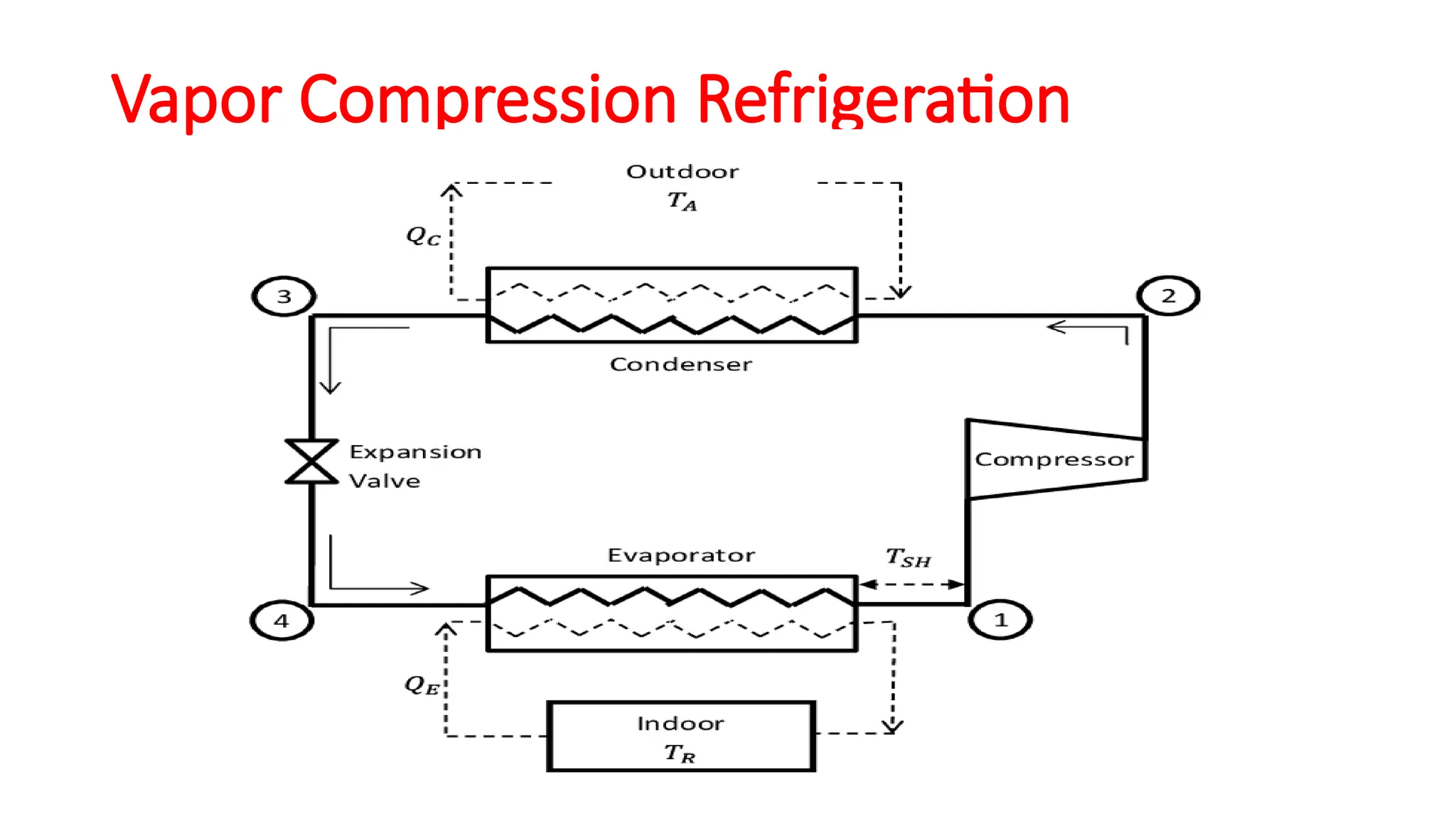
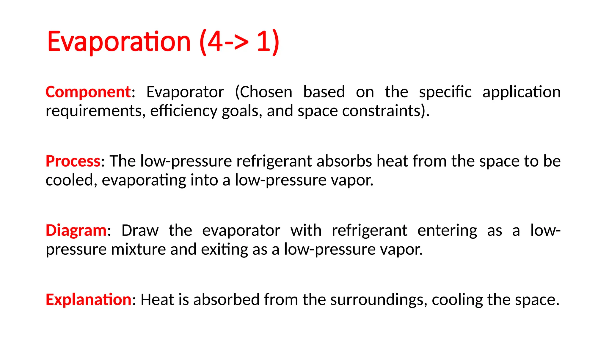
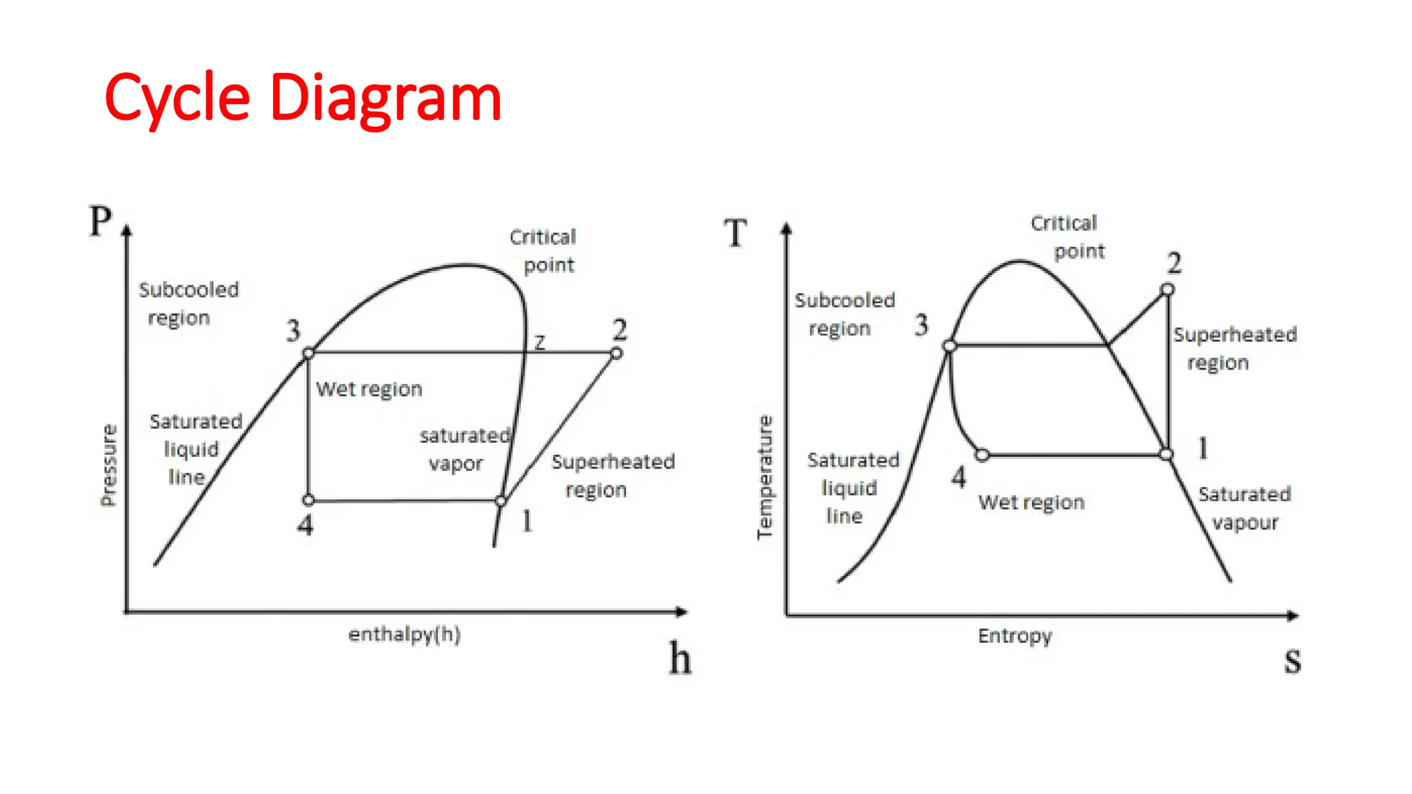
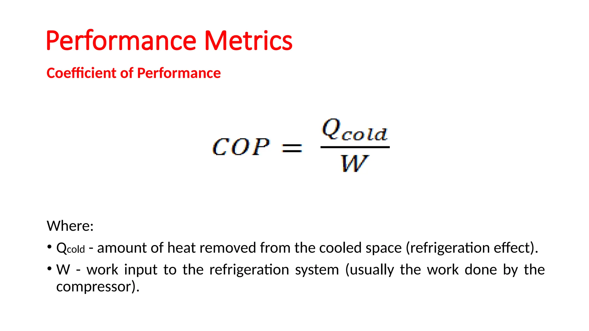
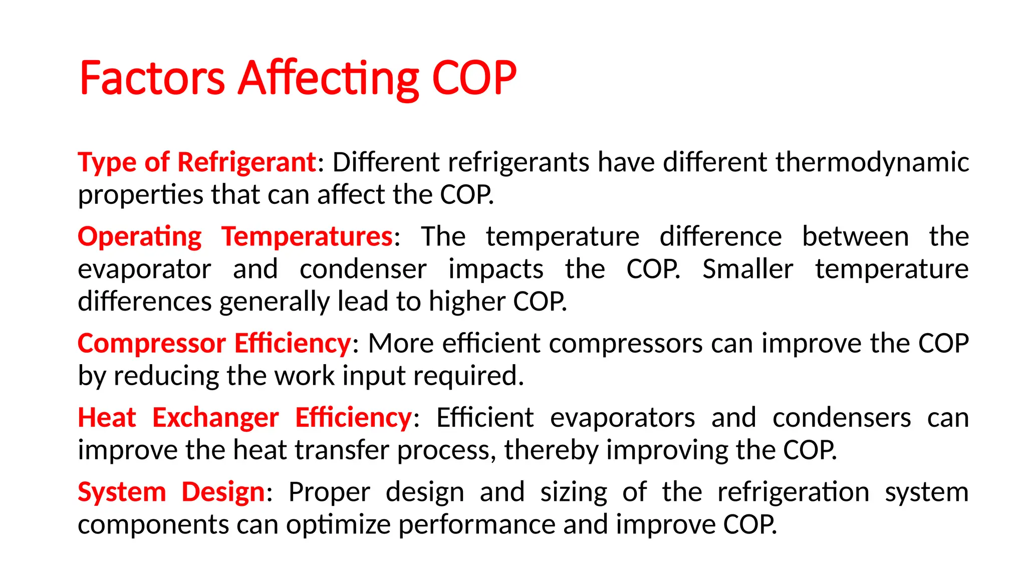
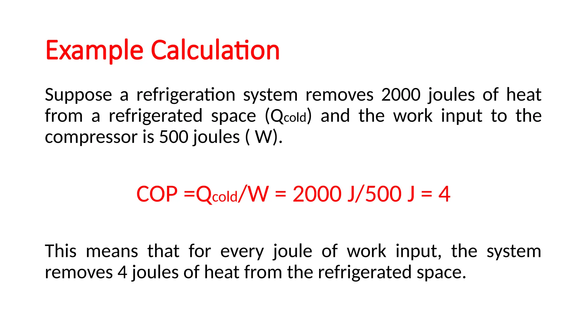
Vapour Compression Refrigeration
Cycle
PRESENTED BY- Dr. ABHISHEK KANSAL
Ph.D., IIT ROORKEE
What is Refrigeration
Purpose of Refrigeration
• The process of cooling a space, substance, or system to a
temperature below the environmental temperature by
removing heat is called refrigeration.
• Preserve food and perishable goods by slowing down
bacterial growth.
• Provide comfort cooling in residential and commercial
buildings.
• Support industrial processes that require specific
temperature conditions.
Principles of Refrigeration
First Law of Thermodynamics: Energy cannot be created or
destroyed, only transferred. In refrigeration, work is done to
transfer heat.
Second Law of Thermodynamics: Heat cannot
spontaneously flow from a colder location to a warmer
location without external work.
Components of a Refrigeration System
Refrigerant: The working fluid that absorbs and releases heat
during the refrigeration cycle.
Compressor: Increases the pressure and temperature of the
refrigerant.
Condenser: Releases absorbed heat from the refrigerant to
the surroundings.
Expansion Valve: Reduces the pressure and temperature of
the refrigerant.
Evaporator: Absorbs heat from the space or substance to be
cooled.
Types of Refrigeration Systems
Vapor Compression Refrigeration: Most common type, used
in household refrigerators and air conditioners.
Absorption Refrigeration: Uses a heat source to drive the
refrigeration cycle, often used in industrial and solar
applications.
Vapor Compression Refrigeration
Compression (1-> 2)
Component: Compressor (chosen based on the requirement of capacity, cost
and efficiency).
Process: The refrigerant enters as a low-pressure vapor and is compressed to
a high-pressure, high-temperature vapor.
Diagram: Draw the compressor showing the input (low-pressure vapor) and
output (high-pressure vapor).
Explanation: Work is done on the refrigerant, increasing its pressure and
temperature.
Condensation (2-> 3)
Component: Condenser (chosen based on the size and capacity,
environment conditions, and efficiency requirements).
Process: The high-pressure vapor releases heat to the surroundings and
condenses into a high-pressure liquid.
Diagram: Draw the condenser with refrigerant entering as a high-pressure
vapor and exiting as a high-pressure liquid.
Explanation: Heat is removed from the refrigerant, causing it to change
phase from vapor to liquid.
Expansion (3-> 4)
• Component: Expansion Valve (chosen based on the system size, load
variation, and cost).
• Process: The high-pressure liquid refrigerant expands, dropping to a low-
pressure, low-temperature mixture of liquid and vapor.
• Diagram: Draw the expansion valve with refrigerant entering as a high-
pressure liquid and exiting as a low-pressure mixture.
• Explanation: Pressure and temperature drop significantly without doing
work.
Evaporation (4-> 1)
Component: Evaporator (Chosen based on the specific application
requirements, efficiency goals, and space constraints).
Process: The low-pressure refrigerant absorbs heat from the space to be
cooled, evaporating into a low-pressure vapor.
Diagram: Draw the evaporator with refrigerant entering as a low-
pressure mixture and exiting as a low-pressure vapor.
Explanation: Heat is absorbed from the surroundings, cooling the space.
Cycle Diagram
Performance Metrics
Coefficient of Performance
Where:
• Qcold - amount of heat removed from the cooled space (refrigeration effect).
• W - work input to the refrigeration system (usually the work done by the
compressor).
Understanding COP
COP > 1: Indicates that the system is efficient, as it
provides more heating or cooling than the work
input.
COP < 1: Indicates that the system is inefficient, as
it requires more work input than the heating or
cooling provided.
Factors Affecting COP
Type of Refrigerant: Different refrigerants have different thermodynamic
properties that can affect the COP.
Operating Temperatures: The temperature difference between the
evaporator and condenser impacts the COP. Smaller temperature
differences generally lead to higher COP.
Compressor Efficiency: More efficient compressors can improve the COP
by reducing the work input required.
Heat Exchanger Efficiency: Efficient evaporators and condensers can
improve the heat transfer process, thereby improving the COP.
System Design: Proper design and sizing of the refrigeration system
components can optimize performance and improve COP.
Example Calculation
Suppose a refrigeration system removes 2000 joules of heat
from a refrigerated space (Qcold) and the work input to the
compressor is 500 joules ( W).
COP =Qcold/W = 2000 J/500 J = 4
This means that for every joule of work input, the system
removes 4 joules of heat from the refrigerated space.
Summary
The coefficient of performance (COP) is a key
indicator of the efficiency of refrigeration and
heating systems. It represents the ratio of useful
heating or cooling provided to the work required
to achieve that heating or cooling. Higher COP
values indicate more efficient systems, leading to
energy savings and reduced environmental
impact.
Thank you

Vapour Compression Refrigeration Cycle.pptx

  • 1.
    Vapour Compression Refrigeration Cycle PRESENTEDBY- Dr. ABHISHEK KANSAL Ph.D., IIT ROORKEE
  • 2.
    What is Refrigeration Purposeof Refrigeration • The process of cooling a space, substance, or system to a temperature below the environmental temperature by removing heat is called refrigeration. • Preserve food and perishable goods by slowing down bacterial growth. • Provide comfort cooling in residential and commercial buildings. • Support industrial processes that require specific temperature conditions.
  • 3.
    Principles of Refrigeration FirstLaw of Thermodynamics: Energy cannot be created or destroyed, only transferred. In refrigeration, work is done to transfer heat. Second Law of Thermodynamics: Heat cannot spontaneously flow from a colder location to a warmer location without external work.
  • 4.
    Components of aRefrigeration System Refrigerant: The working fluid that absorbs and releases heat during the refrigeration cycle. Compressor: Increases the pressure and temperature of the refrigerant. Condenser: Releases absorbed heat from the refrigerant to the surroundings. Expansion Valve: Reduces the pressure and temperature of the refrigerant. Evaporator: Absorbs heat from the space or substance to be cooled.
  • 5.
    Types of RefrigerationSystems Vapor Compression Refrigeration: Most common type, used in household refrigerators and air conditioners. Absorption Refrigeration: Uses a heat source to drive the refrigeration cycle, often used in industrial and solar applications.
  • 6.
  • 7.
    Compression (1-> 2) Component:Compressor (chosen based on the requirement of capacity, cost and efficiency). Process: The refrigerant enters as a low-pressure vapor and is compressed to a high-pressure, high-temperature vapor. Diagram: Draw the compressor showing the input (low-pressure vapor) and output (high-pressure vapor). Explanation: Work is done on the refrigerant, increasing its pressure and temperature.
  • 8.
    Condensation (2-> 3) Component:Condenser (chosen based on the size and capacity, environment conditions, and efficiency requirements). Process: The high-pressure vapor releases heat to the surroundings and condenses into a high-pressure liquid. Diagram: Draw the condenser with refrigerant entering as a high-pressure vapor and exiting as a high-pressure liquid. Explanation: Heat is removed from the refrigerant, causing it to change phase from vapor to liquid.
  • 9.
    Expansion (3-> 4) •Component: Expansion Valve (chosen based on the system size, load variation, and cost). • Process: The high-pressure liquid refrigerant expands, dropping to a low- pressure, low-temperature mixture of liquid and vapor. • Diagram: Draw the expansion valve with refrigerant entering as a high- pressure liquid and exiting as a low-pressure mixture. • Explanation: Pressure and temperature drop significantly without doing work.
  • 10.
    Evaporation (4-> 1) Component:Evaporator (Chosen based on the specific application requirements, efficiency goals, and space constraints). Process: The low-pressure refrigerant absorbs heat from the space to be cooled, evaporating into a low-pressure vapor. Diagram: Draw the evaporator with refrigerant entering as a low- pressure mixture and exiting as a low-pressure vapor. Explanation: Heat is absorbed from the surroundings, cooling the space.
  • 11.
  • 12.
    Performance Metrics Coefficient ofPerformance Where: • Qcold - amount of heat removed from the cooled space (refrigeration effect). • W - work input to the refrigeration system (usually the work done by the compressor).
  • 13.
    Understanding COP COP >1: Indicates that the system is efficient, as it provides more heating or cooling than the work input. COP < 1: Indicates that the system is inefficient, as it requires more work input than the heating or cooling provided.
  • 14.
    Factors Affecting COP Typeof Refrigerant: Different refrigerants have different thermodynamic properties that can affect the COP. Operating Temperatures: The temperature difference between the evaporator and condenser impacts the COP. Smaller temperature differences generally lead to higher COP. Compressor Efficiency: More efficient compressors can improve the COP by reducing the work input required. Heat Exchanger Efficiency: Efficient evaporators and condensers can improve the heat transfer process, thereby improving the COP. System Design: Proper design and sizing of the refrigeration system components can optimize performance and improve COP.
  • 15.
    Example Calculation Suppose arefrigeration system removes 2000 joules of heat from a refrigerated space (Qcold) and the work input to the compressor is 500 joules ( W). COP =Qcold/W = 2000 J/500 J = 4 This means that for every joule of work input, the system removes 4 joules of heat from the refrigerated space.
  • 16.
    Summary The coefficient ofperformance (COP) is a key indicator of the efficiency of refrigeration and heating systems. It represents the ratio of useful heating or cooling provided to the work required to achieve that heating or cooling. Higher COP values indicate more efficient systems, leading to energy savings and reduced environmental impact.
  • 17.