Download to read offline
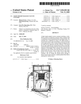
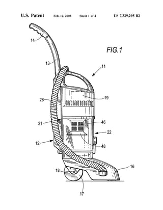
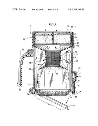
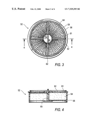
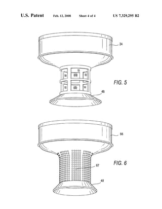
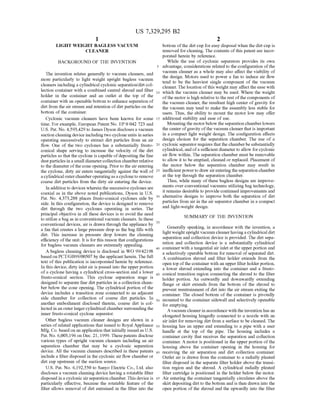

The document describes the United States patent US 7,329,295 B2 for a lightweight bagless vacuum cleaner designed to enhance dirt separation and collection through a cylindrical cyclonic air separation container. It outlines the unique features including a tangential air inlet, a combination shroud and pleated filter cartridge holder, and an easily removable bottom for dirt disposal. The configuration aims to provide improved efficiency and ease of use in a compact design, incorporating a vacuum motor positioned for optimal performance.


