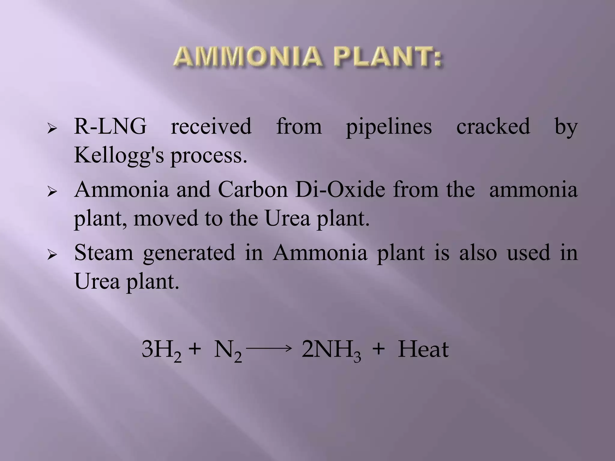
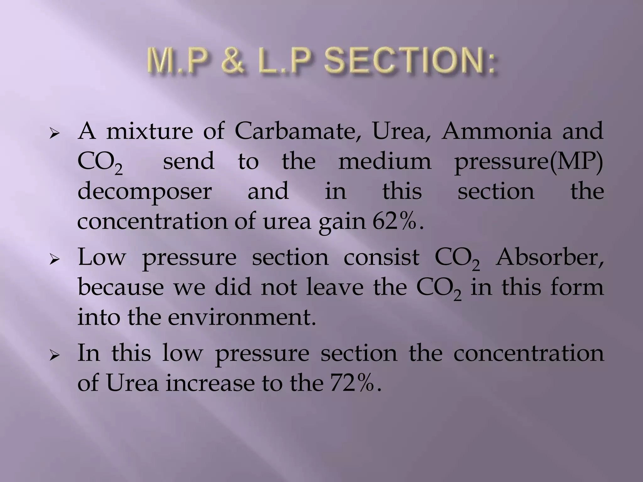
PREPARED BY-
UTKARSH GUPTA
CHEMICAL ENGINEERING
0904351031
IFFCO has four fertilizer plants in India:
 At Phulpur in Uttar Pradesh
 At Kalol in Gujarat
 At Kandla In Gujarat
 At Aonla in Uttar Pradesh
 IFFCO has completed conversion in its largest naphtha based
ammonia urea complex at Phulpur into a gas based unit.
 IFFCO lead to enter an agreement with GAIL in 2004 for
supply of Reliquified Natural Gas (R-LNG).
 IFFCO’s urea is a major source of 46% of nutrients nitrogen
for crops.
 Urea also used as cattle feed supplement.
 It also has numerous industrial uses, as for production of
plastics.
PRODUCT CAPACITY PROCESS
Urea 2380 MT/Day Snam Progetti , Italy
Ammonia 1255 MT/Day Kellogg's, U.S.A
• Power generation plant
• Ammonia synthesis plant
• urea plant
• offsite plant
 reverse osmosis plant
 demineralization plant
 water softening plant
 R-LNG received from pipelines cracked by
Kellogg's process.
 Ammonia and Carbon Di-Oxide from the ammonia
plant, moved to the Urea plant.
 Steam generated in Ammonia plant is also used in
Urea plant.
3H2 + N2 2NH3 + Heat
Urea Plant consist following sections:
 H.P Section (32%)
 M.P Section(62%)
 L.P Section(72%)
 Vacuum Section(99.8%)
 Prilling Section
 NH3(l)and CO2(g)from the Ammonia plant fed
to a reactor at temperature of 168-170°C and a
pressure of 155 Kg/cm2.
2NH3 + CO2 NH2COO NH4 + 38.1K.cal/g.mol
NH2COONH4 NH2CONH2 + H2O
-7.1 K.cal/g.mol
 Carbamate recycled and attain a concentration
of 32%.
 A mixture of Carbamate, Urea, Ammonia and
CO2 send to the medium pressure(MP)
decomposer and in this section the
concentration of urea gain 62%.
 Low pressure section consist CO2 Absorber,
because we did not leave the CO2 in this form
into the environment.
 In this low pressure section the concentration
of Urea increase to the 72%.
 In vacuum section solution brings in 1st
vacuum at 0.3 atmospheric pressure and in 2nd
vacuum at 0.03 atmospheric pressure.
 In vacuum section concentration of urea
increase to 99.8%.
 With the help of molten urea pumps urea send
to the top of the Prilling tower.
 Urea has a melting point of 132.6 °C.
 Air by natural draft flows upward and counter
currently and cools and solidify Urea droplets.
 Solid prills fall to the bottom and sent on to a
belt conveyor by means of a rotating scrapper,
urea prills are then transported to bagging
plants through belt conveyor.
Moisture % by weight, maximum 1.0
Total N % by weight (on dry basis) minimum 46.0
Biuret % by weight, maximum 1.5
Particle size 90% of the material shall pass
through 2.8 mm IS sieve and
not less than 80% by weight
shall be retained on 1 mm IS
sieve.
 Corrosion
 Biuret Formation:
2 NH2CONH2 NH2 CO NH CO NH2 + NH3
(Urea) (Biuret )
 The formation of biuret is favored by higher
temperature, higher concentration of urea solution, low
NH3 content and higher residence time.
Urea plant

Urea plant

  • 1.
  • 2.
    IFFCO has fourfertilizer plants in India:  At Phulpur in Uttar Pradesh  At Kalol in Gujarat  At Kandla In Gujarat  At Aonla in Uttar Pradesh
  • 3.
     IFFCO hascompleted conversion in its largest naphtha based ammonia urea complex at Phulpur into a gas based unit.  IFFCO lead to enter an agreement with GAIL in 2004 for supply of Reliquified Natural Gas (R-LNG).  IFFCO’s urea is a major source of 46% of nutrients nitrogen for crops.  Urea also used as cattle feed supplement.  It also has numerous industrial uses, as for production of plastics.
  • 4.
    PRODUCT CAPACITY PROCESS Urea2380 MT/Day Snam Progetti , Italy Ammonia 1255 MT/Day Kellogg's, U.S.A
  • 5.
    • Power generationplant • Ammonia synthesis plant • urea plant • offsite plant  reverse osmosis plant  demineralization plant  water softening plant
  • 6.
     R-LNG receivedfrom pipelines cracked by Kellogg's process.  Ammonia and Carbon Di-Oxide from the ammonia plant, moved to the Urea plant.  Steam generated in Ammonia plant is also used in Urea plant. 3H2 + N2 2NH3 + Heat
  • 7.
    Urea Plant consistfollowing sections:  H.P Section (32%)  M.P Section(62%)  L.P Section(72%)  Vacuum Section(99.8%)  Prilling Section
  • 9.
     NH3(l)and CO2(g)fromthe Ammonia plant fed to a reactor at temperature of 168-170°C and a pressure of 155 Kg/cm2. 2NH3 + CO2 NH2COO NH4 + 38.1K.cal/g.mol NH2COONH4 NH2CONH2 + H2O -7.1 K.cal/g.mol  Carbamate recycled and attain a concentration of 32%.
  • 10.
     A mixtureof Carbamate, Urea, Ammonia and CO2 send to the medium pressure(MP) decomposer and in this section the concentration of urea gain 62%.  Low pressure section consist CO2 Absorber, because we did not leave the CO2 in this form into the environment.  In this low pressure section the concentration of Urea increase to the 72%.
  • 11.
     In vacuumsection solution brings in 1st vacuum at 0.3 atmospheric pressure and in 2nd vacuum at 0.03 atmospheric pressure.  In vacuum section concentration of urea increase to 99.8%.  With the help of molten urea pumps urea send to the top of the Prilling tower.
  • 12.
     Urea hasa melting point of 132.6 °C.  Air by natural draft flows upward and counter currently and cools and solidify Urea droplets.  Solid prills fall to the bottom and sent on to a belt conveyor by means of a rotating scrapper, urea prills are then transported to bagging plants through belt conveyor.
  • 13.
    Moisture % byweight, maximum 1.0 Total N % by weight (on dry basis) minimum 46.0 Biuret % by weight, maximum 1.5 Particle size 90% of the material shall pass through 2.8 mm IS sieve and not less than 80% by weight shall be retained on 1 mm IS sieve.
  • 14.
     Corrosion  BiuretFormation: 2 NH2CONH2 NH2 CO NH CO NH2 + NH3 (Urea) (Biuret )  The formation of biuret is favored by higher temperature, higher concentration of urea solution, low NH3 content and higher residence time.