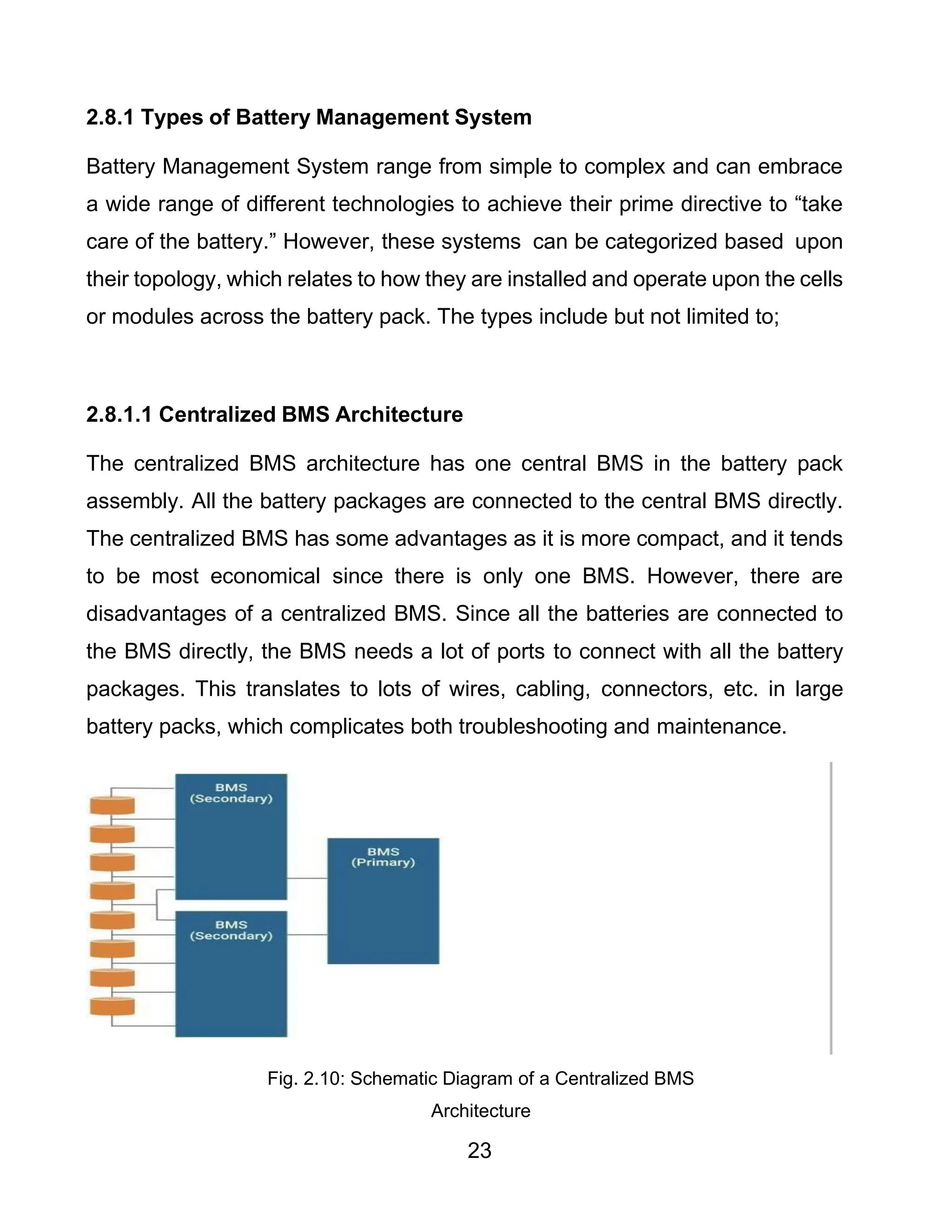
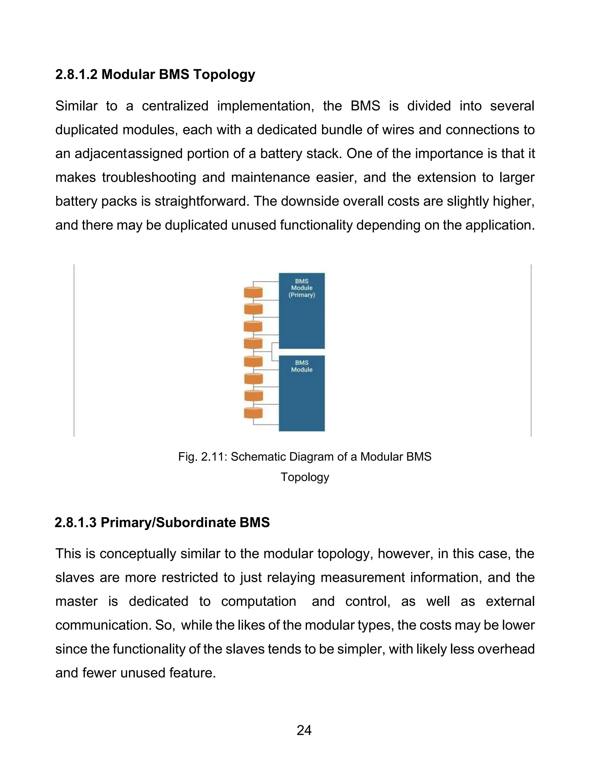
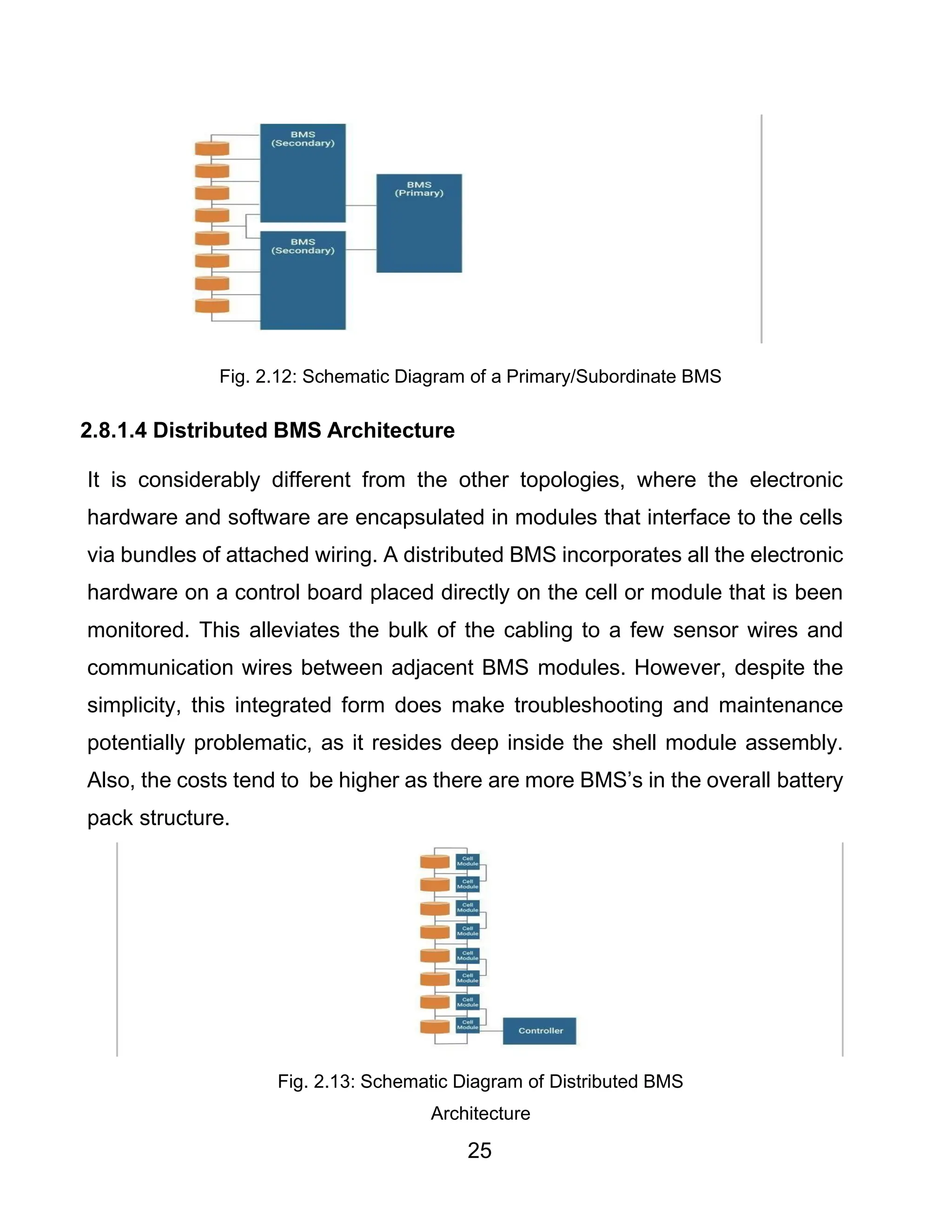
SlideShare a Scribd company logo
1 of 77
Download to read offline
UPGRADE OF A 1,476.3W RECHARGEABLE BATTERY POWERED
AIRCRAFT GPU TO 2KW AND INSTALLING BMS; POWER
RECEPTACLE
BY
AJIBOLA SAMSON TOBI AFIT/ND/AET/20/030
AIRCRAFT ENGINEERING TECHNOLOGY DEPARTMENT,
FACULTY OF ENGINEERING,
AIRFORCE INSTITUTE OF TECNOLOGY
KADUNA, NIGERIA
JANUARY, 2024
i
UPGRADE OF A 1,476.3W RECHARGEABLE BATTERY POWERED
AIRCRAFT GPU TO 2KW AND INSTALLING BMS; POWER
RECEPTACLE
BY
AJIBOLA SAMSON TOBI AFIT/ND/AET/20/030
A PROJECT REPORT SUBMITTED TO THE AIRCRAFT ENGINEERING
TECHNOLOGY DEPARTMENT, FACULTY OF ENGINEERING,
AIRFORCE INSTITUTE OF TECHNOLOGY, KADUNA. IN PARTIAL
FULFILMENT OF THE REQUIREMENTS FOR THE AWARD OF
NATIONAL DIPLOMA IN AIRCRAFT ENGINEERING TECHNOLOGY
JANUARY, 2024
ii
ABSTRACT
This paperwork presents the upgrade of a rechargeable battery powered
aircraft ground power unit (GPU) with a battery management system (BMS)
and receptacle installed. The objective is to upgrade an existing simple,
modernized and portable rechargeable battery powered GPU that can
supply 2KW power output to sustain aircraft flight activities on the flight line.
The components used for this research are Lithium-ion cells, cables, main
on/off switch, Diode Bridge, relay switch, transistors, capacitors, circuit
breaker, digital voltage display, battery management system (BMS), power
receptacle and other accessories. In this research, one hundred and twenty-
eight lithium-ion batteries (3.7V, 5A rating) were utilized and connected in
series-parallel to obtain the required total output of 26-28 volts and 67.567
amps. The output of the GPU was delivered to the air beetle ABT-18 aircraft
through the power receptacle. The system developed has proved that a
GPU system can be low cost, portable, with the battery being monitored by
the BMS as well as supplying the required output.
iii
DECLARATION
I, AJIBOLA SAMSON TOBI, hereby declare that this project work titled
“upgrade of a 1,476.3W rechargeable battery powered aircraft GPU to 2KW
and installing BMS; power receptacle” has been solely carried out by me
under the supervision of MWO AYUBA S.N in the Aircraft Engineering
Technology Department. The research work is authentic and is a product of
my effort. All literatures and contributions have been duly and respectfully
acknowledged.
AJIBOLA SAMSON TOBI ______________________
(ND/AET/20/030) Signature/Date
iv
CERTIFICATION
This is to clarify that this project titled UPGRADE OF A 1,476.3W
RECHARGEABLE BATTERY POWERED GPU 2KW AND INSTALLING
BMS; POWER RECEPTACLE BY AJIBOLA SAMSON TOBI, has been
read and approved in partial fulfillment the award of National Diploma in
Aircraft Engineering Technology Department, Faculty of Engineering, Air
Force Institute of Technology, Kaduna.
MWO AYUBA S.N ________________________
(project supervisor) Signature/Date
v
APPROVAL
This project work titled ’upgrade of a 1,476.3W rechargeable battery
powered aircraft GPU to 2KW and installing BMS; power receptacle by
AJIBOLA SAMSON TOBI has fulfilled the partial requirements for the award
of National Diploma in Aircraft Engineering Technology in the Department of
Aircraft Engineering Technology of the Air Force Institute of Technology,
Kaduna and hereby approved.
MWO AYUBA S.N __________________________
(Project Supervisor) Signature/Date
MR. NANDOM LWAHAS __________________________
(Project coordinator) Signature/Date
SQN LDR YI HARUNA __________________________
(HOD, AETD) Signature/Date
GP CAPT G ISA __________________________
(Dean, Faculty of Engineering) Signature/Date
vi
DEDICATION
I dedicate this project to God Almighty our creator, strong pillar, my source of
inspiration, wisdom, knowledge and understanding. He has been the source
of my strength throughout this project research and in the course of running
my program. I also dedicate this work to my family members who has
encouraged me all the way.
viii
ACKNOWLEDGEMENTS
I am grateful to God Almighty for his provision of knowledge, guidance,strength
and protection throughout the course of this project.
my sincere gratitude goes to my supervisor, MWO AYUBA S.N, for his
counseling, all through the project. The distinguished contribution and technical
advice he gave while carrying out this project enabled me to accomplish the
project.
I also appreciate the tireless effort of my project coordinator, MR. NANDOM
LWAHAS.
My gratitude is also extended to my lecturers and instructors in the department
for their tireless effort in tutoring and impacting knowledge and notable skills.
The efforts of my family are also appreciated for their moral and financial
support throughout the course.
ix
TABLE OF CONTENTS
ABSTRACT....................................................................................................................ii
DECLARATION ............................................................................................................iii
CERTIFICATION ..........................................................................................................iv
APPROVAL ...................................................................................................................v
DEDICATION................................................................................................................vi
ACKNOWLEDGEMENTS ...........................................................................................viii
CHAPTER ONE
INTRODUCTION
1.1 BACKGROUND OF STUDY ....................................................................................1
1.2 STATEMENT OF THE PROBLEM...........................................................................1
1.3 FEATURES OF THE CONSTRUCTION ..................................................................2
1.4 AIM AND OBJECTIVES...........................................................................................3
1.4.1 Aim.................................................................................................................... 3
1.4.2 Objectives ......................................................................................................... 3
1.5 SIGNIFICANCE OF THE PROJECT........................................................................4
1.6 PURPOSE OF THE STUDY ....................................................................................4
1.7 SCOPE ....................................................................................................................4
CHAPTER TWO
LITRATURE REVIEW
2.1 INTRODUCTION .....................................................................................................5
2.2 REVIEW OF RELATED WORKS .............................................................................6
x
2.2.1 Aircraft Batteries: Current Trend Towards More Electric Aircraft ....................... 6
2.2.2 Airport Installation Of GPU ................................................................................ 7
2.2.3 Electricity Production from Renewable Energies ............................................... 8
2.2.4 Construction of a 1476.3W Ground Power Unit................................................. 8
2.2.5 A New Control Method for Ground Power Units for Airplanes ........................... 9
2.3 GAPS IDENTIFIED IN THE LITERATURE.............................................................10
2.4 THEORETICAL BACKGROUND OF THE STUDY.................................................11
2.5 GROUND SUPPORT EQUIPMENT (GSE) ............................................................13
2.6 REVIEW OF RECHARGEABLE BATTERIES ........................................................13
2.6.1 Nickel-Metal Hydride (NiMH) Battery ................................................................14
2.6.1.1 Application of Nickel-metal Hydride Batteries Include; ................................15
2.6.2 Lead-Acid Batteries ..........................................................................................15
2.6.2.1 The advantages of Lead-acid battery are; ..................................................16
2.6.2.2 The limitations of Lead-acid battery are; .....................................................17
2.6.3 Nickel Cadmium Battery ...................................................................................17
2.6.3.1 The Advantages of Nickel-Cadmium Battery are;........................................18
2.6.3.2 The Limitations of Nickel-Cadmium Battery are; .........................................18
2.6.4 Lithium-Ion Battery ...........................................................................................19
2.7 REVIEW OF BATTERY CHARGERS.....................................................................20
2.7.1 Simple Battery Charger ....................................................................................21
2.7.2 Smart Charger..................................................................................................21
2.7.3 Solar Charger...................................................................................................21
xi
2.7.4 Universal Charger.............................................................................................22
2.8 BATTERY MANAGEMENT SYSTEM ....................................................................22
2.8.1 Types of Battery Management System .............................................................23
2.8.1.2 Modular BMS Topology ..............................................................................24
2.8.1.3 Primary/Subordinate BMS ..........................................................................24
2.8.1.4 Distributed BMS Architecture......................................................................25
2.8.1.5 The Benefits of Battery Management System.............................................26
2.9 RECEPTACLE REVIEWS......................................................................................26
2.10 THEORETICAL BACKGROUND..........................................................................26
2.10.1 Design Analysis..............................................................................................27
2.10.2 Applicable Equations......................................................................................28
CHAPTER THREE
RESEARCH METHODOLOGY
3.1 INTRODUCTION ...................................................................................................29
3.2 BLOCK DIAGRAM.................................................................................................29
3.3 COMPONENT SELECTION...................................................................................30
3.3.1.1 Mains On/Off Switch...................................................................................30
3.3.1.2 Diode Bridge...............................................................................................30
3.3.1.3 Relay Switches...........................................................................................31
3.3.1.4 Transistor ...................................................................................................32
3.3.1.5 Circuit Breaker............................................................................................32
3.4 POWER REQUIREMENT CHART FOR EACH COMPONENT..............................33
xii
3.5 WORKING PRINCIPLE OF THE GPU ...................................................................33
3.5.1 Circuit Diagram and Battery Installation............................................................33
3.5.2 CIRCUIT DIAGRAM OF THE GPU...................................................................34
3.5.3 How the GPU Can Be Used on The Aircraft .....................................................35
3.6 MATHEMATICAL CALCULATION AND DERIVATION OF GPU OUTPUT............35
3.6.1 For Cell/ Bracket / Charging Configuration: ......................................................35
3.6.2 Cell Number/ Configuration to Obtain 67.567A.................................................36
3.7 CHARGING AND DISCHARGING - HOW LITHIUM BATTERIES FUNCTION.......37
3.7.1 Discharge.........................................................................................................37
3.7.2 Charging ..........................................................................................................38
3.7.2.1 Pre-charge mode......................................................................................38
3.7.2.2 Regulation mode ......................................................................................39
3.7.2.3 Constant Voltage Regulation Mode ..........................................................39
3.7.2.4 The Separator ..........................................................................................39
3.8 LIFE SPAN, DISCHARGE RATE AND BATTERY HEALTH...................................40
3.9 ADVANTAGES AND DISADVANTAGES OF LITHIUM-ION BATTERY .................40
3.9.1 Advantages of Lithium-Ion Battery....................................................................40
3.9.2 Disadvantages of Lithium-Ion Battery ...............................................................40
3.9.3 Application of Lithium-ion Batteries...................................................................41
3.10 Wiring and Soldering............................................................................................41
3.10.1 Soldering Tools ..............................................................................................42
3.10.2 How to Solder Wires.......................................................................................42
xiii
3.10.3 General Soldering Procedure .........................................................................43
3.11 BATTERY MANAGEMENT SYSTEM (BMS)........................................................44
3.12 BILL OF ENGINEERING QUANTITIES FOR THE UPGRADE OF THE GROUND
POWER UNIT..............................................................................................................46
3.13 3D COMPUTER AIDED DESIGN (CAD) OF GROUND POWER UNIT (GPU).....47
CHAPTER FOUR
TESTS, MEASURMENTS AND RESULTS
4.1 INTRODUCTION ...................................................................................................48
4.2 TESTS CONDUCTED ON RECHARGEABLE GPU ...............................................48
4.2.1 Output Test.......................................................................................................48
4.2.1.1 Measurements..........................................................................................48
4.2.1.2 Results .....................................................................................................49
4.2.2 Restart Test......................................................................................................49
4.2.2.1 Measurements............................................................................................49
4.2.2.2 Interpretation ..............................................................................................49
4.2.2.3 Results .......................................................................................................50
4.2.3 Endurance Test................................................................................................50
4.2.3.1 Measurements............................................................................................50
4.2.3.2 Results .......................................................................................................50
4.2.4 Lifespan Test....................................................................................................51
4.2.4.1 Test ............................................................................................................51
4.2.4.2 Results .......................................................................................................51
xiv
4.2.5 Weather Effect Test..........................................................................................52
4.2.5.1 Measurements............................................................................................52
4.2.5.2 Results .......................................................................................................52
4.2.6 Crash Test........................................................................................................52
4.2.6.1 Measurements:...........................................................................................52
4.2.6.2 Results: ......................................................................................................53
4.3 SUMMARY TABLE FOR TESTS, MEASUREMENTS AND RESULTS...................53
4.3.1 Table Showing the Test, Measurement and Results Carried Out ......................53
CHAPTER FIVE
DISCUSSION, SUMMARY AND CONCLUSION
5.1 DISCUSSION …………………………………………………………………………….57
5.2 SUMMARY ............................................................................................................57
5.3 CHALLENGES.......................................................................................................57
5.4 RECOMMENDATION ............................................................................................58
5.5 CONCLUSION.......................................................................................................58
REFERENCES ............................................................................................................59
xv
LIST OF FIGURES
CHAPTER TWO
Fig 2.1: Airbus and Boeing aircraft electric power generation capacity 6
Fig 2.2: Proposed topology for a new aircraft ground power unit 7
Fig 2.3: Greenhouse gas emission chart 8
Fig 2.4: Diagram of a 1500w GPU 9
Fig 2.5: Proposed control concept of a Ground Power Unit for air-planes 10
Fig 2.6: Application of Ground Power Unit Between Landing and Takeoff 12
Fig 2.7: Diagram of Lead Acid Battery 16
Fig 2.8: Diagram of Nickel-Cadmium Battery 18
Fig 2.9: Diagram of Lithium-Ion Battery 19
Fig. 2.10: Schematic Diagram of a Centralized BMS Architecture 24
Fig. 2.11: Schematic Diagram of a Modular BMS Topology 25
Fig. 2.12: Schematic Diagram of a Primary/Subordinate BMS 25
Fig. 2.13: Schematic Diagram of Distributed BMS Architecture 26
CHAPTER THREE
Fig 3.1: Block diagram for the project work 30
Fig 3.2: Diagram of a diode bridge 32
Fig 3.3: Diagram of a relay switch 32
Fig 3.4: Diagram of a transistor 33
Fig 3.5: Circuit diagram of the GPU construction 35
Fig 3.6: Operation and structure of Lithium-ion battery 38
Fig 3.7: Diagram showing a soldered wire 44
Fig 3.8: Diagram showing how to solder 45
Fig 3.9: Diagram of a 3D computer aided design of ground power unit 48
xvi
LIST OF TABLES
Table 3.1: Table showing power requirements charts 34
Table 3.2: Table showing bill of engineering chart 47
Table 4.1: Table showing the various test carried out 56
LISTS OF ACRONYMS AND ABBREVIATIONS
Acronyms Meaning
NATO North Atlantic Treaty
Organization
ICAO International Civil Aviation
Organization
Abbreviations Meaning
AC Alternating Current
APU Auxiliary Powe Unit
BMS Battery Management System
DC Direct Current
GPU Ground Power Unit
GSE Ground Support Equipment
ITW Illinois Tool Works Inc
LED Light Emitting Diode
PSU Power Supply Unit
UPS Uninterrupted Power Supply
1
CHAPTER ONE
INTRODUCTION
1.1 BACKGROUND OF STUDY
In the aviation industry, ground power units (GPU’s) are considered a vital
equipment in providing electrical power supply for starting and maintaining of
the aircraft while they are parked at the hanger or apron. A Ground Power
Unit (GPU) can be either a fixed or mobile unit which can be connected to the
electrical system of an aircraft while on ground to provide either 120V AC or
28V DC power. Ground power units usually consist of a generator powered
by a diesel engine but may be found in other configurations.
However, with the increasing demand for larger aircraft and advanced
onboard systems, the existing 1476.3-watt GPU units are becoming
inadequate. This project proposal aims to upgrade the current 1,476.3-watt
GPU capacity to 2,000-watt, while also incorporating abattery management
system (BMS) for enhanced efficiency and also the installation of a GPU
receptacle to ensure compatibility with various aircraft types.
1.2 STATEMENT OF THE PROBLEM
The current 1,476.3-watt GPU was designed to cater to the power
requirements of older aircraft models with lower electrical demands. However,
with the continuous advancementin aviation technology, modern aircraft now
feature advanced avionics, entertainment systems, and electrical components
that require higher power capacity during ground operations. Thus, the
1,476.3-watt GPU may fall short in providing the necessary electrical energy,
leading to delays in pre-flight preparations and potential disruptions in ground
operations.
2
Incorporating a BMS into the upgraded GPU is essential for efficient battery
performance and maintenance. A BMS is responsible for monitoring,
controlling, and optimizing the battery's charging and discharging cycles. It
helps prevent overcharging, over- discharging, and ensures uniform
distribution of power across the battery cells, thereby extending the battery's
lifespan. Without a BMS, the GPU's battery may experience premature
deterioration, leading to decreased reliability and additional maintenance cost
(
Basile et al, 2020).
In the absence of a standardized GPU receptacle, connecting the GPU to
different aircraft can be challenging. Various aircraft models may have
different power input requirements and connector types. Integrating a GPU
receptacle in the design of the GPU provides a universal and standardized
connection point, making it compatible with a wide range of aircraft. This
inclusion simplifies the process of ground power supply, reduces the risk of
misconnections, and enhances overall safety during aircraft turnaround
operations (Zhu et al, 2019).
1.3 FEATURES OF THE CONSTRUCTION
Listed below are characteristics of the construction;
1. 28 Volts DC output
2. Mains ON/OFF switch
3. Battery Management System (BMS)
4. GPU Receptacle
3
5. Corrosion resistance case with handle
6. Ventilated case for cooling
7. Charging set
8. Display unit (voltage or current)
9. Charging cord
10.Battery control switch
11.Input and output plugs
12.Circuit breaker
1.4 AIM AND OBJECTIVES
1.4.1 Aim
The aim of this project is to upgrade the existing 1,476.3-watt Ground Power
Unit (GPU) to 2000-watt system with a Battery Management System (BMS)
and a GPU receptacle.
1.4.2 Objectives
1. To upgrade the existing 1,476.3W GPU to a 2000 - watt GPU.
2. To integrate a Battery Management System (BMS) into the upgraded
GPU. The BMS will be responsible for monitoring and optimizing the
performance of the GPU's battery.
3. To include a GPU receptacle as part of the upgrade. The GPU receptacle
will serve as a standardized connection point from the GPU to the aircraft.
4. To ensure seamless integration of the upgraded GPU with different
aircraft systems.
4
1.5 SIGNIFICANCE OF THE PROJECT
The GPU is a device which its importance in the aviation field cannot be
overemphasized. Its availability is crucial for the day to day running of flight line
operations. Due to the insufficient power output from the previous ground power
unit, this project is planned to have an increased power output that will offer
efficient power for the aircraft. Electrical andchemical energy are the two types
of energy that will be utilized. Therefore, the importance of this project is to
increase the power output of the GPU from 1,476.3W to 2000W and to give
engineering students a technical and practical knowledge and understanding in
the application of the ground power unit on the aircraft and also to generally
serve as a teaching aid for lecturers and students in the aspect of carrying out
practical exercises.
1.6 PURPOSE OF THE STUDY
The purpose of this project is to prove the possibility of developing aircraft parts
and support equipment locally. With the required funding and continuous
research and development (R and D), in AFIT and even the aviation industry at
large can begin the development of aircrafts parts and support equipment.
1.7 SCOPE
To upgrade a rechargeable battery powered GPU that will supply the required
power output (2000W) to sustain aircraft flight activities on the flight line most
especially in the absence of fuel or engine driven GPU and in location where
such big and heavy GPU are not accessible.
5
CHAPTER TWO
LITERATURE REVIEW
2.1 INTRODUCTION
Ground power units (GPU’s) are considered as power supply for aircrafts in
military and civil aviation, ships, radar and others. The machinery is meant to
be established in airports and employed as the electrical power supply for
airplanes during refueling and loading operations. This is preferable with the
goal of reducing costs, because the power can be converted on the ground in
a cheap and efficient way than burning jet fuel on the airplane (Jensen et-al,
2018).
A ground power unit can be either be a fixed or mobile unit which can be
connected to the electrical system of an aircraft while on the ground to provide
either 120V AC or 28V DC power. It usually consists of a generator powered by
a diesel engine but may be found in other configurations. A mobile GPU is a
source of ground power to the aircraft and its components, and also the GPU
comprises of several components like power receptacle, battery, control switch
etc.
The GPU is connected through a cable to the aircraft and provides the
necessary electrical power to operate the on-board systems. It is an external
power source providing a power supply for the aircraft system, engine starting
and aircraft servicing while on ground. Battery power supply is a combination
of both electrical and battery power supply to the aircraft. A GPU can be referred
to a dedicated DC power supply, battery-powered unit, diesel generator,
electrically power GPU, or a combination of both diesel generator and battery
6
power (Hybrid units). They are fully airworthy, with no calibration or settings,
they can simply be plugged directly into the aircraft for quiet dependable power
supply, batteries provided the main source of electricity before the development
of electric generators and electric grids around the end of the 19th century. One
of the most important discoveries in the last 400 years is electricity. One
important classification for batteries is by their life cycle. "Primary" batteries can
provide current as soon as they are built, but they cannot be electrically refilled
once the active materials have been exhausted. The invention of the lead-acid
battery and later "secondary" or "chargeable" varieties allowed energy to be
returned to the cell, allowing permanently built cells to be extended in life (Feng-
Cheng. 2021).
2.2 REVIEW OF RELATED WORKS
2.2.1 Aircraft Batteries: Current Trend Towards More Electric Aircraft
In 2021 Tariq et al carried out a study that presents an overview of the battery
systems for battery. In this paper, a study on the battery technologies used in
aircraft in the last five decades was being done. A general background of the
battery system is presented and the performance of the batteries based on
energy densities and low temperature capabilities are evaluated and discussed.
Evolution of aircraft batteries with its power system architecture and load profile
is presented to understand the requirements of the battery system. Weight
saving and cost analysis is done for the Li-ion and Ni-Cd batteries with respect
to the requirement, (Tariq et al, 2021)
7
Fig. 2.1: Airbus and Boeing aircraft electric power generation capacity
2.2.2 Airport Installation Of GPU
In 2020, bosolo G et al carried out a project on GPU, his design focus on the
analysis, design and prototyping in reduced scale of a digitally controlled
inverter for uninterruptible power supply (UPS) applications. The converter is
rated for 100 kVA nominal power and 400 Hz, three-phase, 220 V sinusoidal
output voltage. The final equipment is meant to be installed in airport docks and
used as the aircraft's electrical power supply during refueling and loading
operations. It was manufactured with different power ratings ranging from 30 to
300 kVA. The power converter and digital control circuits are devised to provide
rated voltage and frequency with a fairly low output impedance. (Bosolo et al,
2020)
Fig. 2.2: Proposed topology for a new aircraft ground power unit
8
2.2.3 Electricity Production from Renewable Energies
In 2018, Robyns et al contributed to a better understanding of the new electricity
generation technologies by addressing a diverse audience. The study presents
the issues, sources and means of conversion into electricity using a general
approach and develops scientific concepts to understand their main technical
characteristics. Systems of electricity generation from renewable energy
resources of small to medium powers are presented. The basic electrical
concepts necessary for understanding the operating characteristics of these
energy converters are introduced, and the constraints and problems of
integration in the electrical networks of those means of production are
discussed ( Robyns et al, 2018).
Fig. 2.3: Greenhouse Gas Emission Chart
2.2.4 Construction of a 1476.3W Ground Power Unit
In 2022 Ekpang et al, constructed a 1476.3W power output rechargeable
9
battery powered aircraft GPU, the GPU was fitted with several lithium-ions
batteries rated 3.7V, 3.8A, circuit breakers, digital voltage display that could
power the aircraft and sustain aircraft flight activities on the flight line and also
in the aircraft engineering hanger (Ekpang et al 2022).
Fig. 2.4: Diagram of a 1500w GPU
2.2.5 A New Control Method for Ground Power Units for Airplanes
In 2018 Jensen U, presented a new control strategy for aground power unit,
which is used for airplanes on the ground in the system, the ratio between the
switching frequency and the fundamental frequency is low, and in order to
obtain high output performance, the controller has to be digital. The control is
performed by a pulse width modulator and a voltage controller in the
synchronously rotating reference frame. Design rules are given and a simulation
tool is used for investigation of the controller. A 90-kVA prototype is used for
validation of the principle. It is concluded by the experiments that the new
controller gives a high output performance both stationary and dynamically at
10
linear and nonlinear loads. Synchronization with the airplane is also shown to
work successfully (Jensen et al, 2018).
Fig. 2.5: Proposed control concept of a Ground Power Unit for air-planes
2.3 GAPS IDENTIFIED IN THE LITERATURE
a. From 2.2.1, Aircraft Batteries: Current Trend Towards More Electric
Aircraft: This study only focuses on the analysis of Li-ion Batteries and
Ni-cadmium batteries without putting into consideration order form of
batteries like the lead acid and Nickel-Metal hydride.
b. From 2.2.2, Airport Installation Of GPU: The device crafted is sizable
and lacks portability, boasting considerable dimensions, making its use
limited.
c. From 2.2.3, Electricity Production from Renewable Energies: Only
Basic concepts for understanding the operating characteristics of the
energy converter in the article was introduced and also the constraint
associated with integration of electrical networks was discussed but no
solution was provided.
11
d. From 2.2.4, Construction of a 1476.3W Ground Power Unit: We
discovered that the GPU had no receptacle which is used as a connector
between the aircraft and the GPU and also a Battery management
system which helps to organize in a row configuration to enable delivery
of targeted range of voltage and current for a duration of time against
load scenarios.
e. From 2.2.5 A New Control Method for Ground Power Units for
Airplane: In the article only a 90-kVA prototype was designed and used
to carryout testing to validate the function of the new controller on the
Ground Power Unit.
2.4 THEORETICAL BACKGROUND OF THE STUDY
This entails the theory of our work describing the components used for
construction and the design specification. To achieve this project titled
"Upgrade of a rechargeable battery powered aircraft GPU from 1,476.3-W to
2,000W for flight line operations", the following component will be used:
1) Lithium-ion batteries connected in series and in parallel,
2) power receptacle/connector and
3) control switch/circuit breaker.
Several electrical connections will be made via the: use of soldering iron, it will
be connected to the battery via the use of cables thus, analogue meter will be
used to read the output. The switch on the other hand will be used to control
on/off of the system. The battery will serve as power supply and power storage
for the system while the receptacle will serve as the point of connection to the
aircraft and the power supply. The outer casing will be built with corrosion
12
resistive plastic material and it will serve as container that will contain all the
inbuilt system. Careful observation will be practiced to ascertain that thereis
no breach of connection from the wire to the container to prevent fire outbreak
(Rohouma et al, 2019).
Fig. 2.6: Application of Ground Power Unit Between
Landing and Takeoff
13
2.5 GROUND SUPPORT EQUIPMENT (GSE)
As the name implies, Ground Support Equipment is there to support the
operations of aircraft whilst on the ground. The role of this equipment generally
involves ground power operations, aircraft mobility, and cargo/passenger
loading. This is the support equipment found at an airport, usually on the apron,
the servicing area by the terminal. This equipment is used to service the aircrafts
between flights. Ground Support Equipment is generally kept on a ramp near
the terminal when not in use for quick accessibility. GSE means vehicles, mobile
equipment, tank vehicles, refueling vehicles, tugs, carts, GPUs and any other
equipment used to service aircraft (Kennedy, 2018).
GSE’s main purpose is to support the safe operations of the aircraft after landing
and before taking off again. The Ground Support Equipment is of two types
namely:
• Powered Equipment e.g., Forklifts, refuelers, tugs, GPU’s, etc.
• Non-powered Equipment e.g., Chocks, tripod jacks, tow-bars, etc.
2.6 REVIEW OF RECHARGEABLE BATTERIES
A review is given of the major requirements of airplane secondary batteries, with
emphasis on commercial airplane batteries. As one of the most important
elements of our construction design, batteries must satisfy strict requirements
that depend mainly on system architecture and configuration, operating
conditions and load profiles.
Since the batteries commonly used are vented, electrolyte loss is an important
cause of the need for periodic maintenance. Reduced maintenance, high
reliability and low cost of ownership are the main objectives of future aircraft
14
batteries. Particularly, aerospace batteries have to be light and small, deliver
high power in a reliable and safe manner over any operating condition, and last
for a long time. However, in spite of recent improvements in energy storage
technologies, some of these requirements are far from being fully satisfied.
specific energy and power, as well as power and energy density, are some
of the main critical parameters of aerospace batteries because they
determine their size and weight
In particular, since high currents are required during engine starting, the battery
pack have to deliver such a high power. Outlined below are different types of
batteries:
i. Nickel-Metal Hydride (Ni-MH) Battery
ii. Lead Acid Battery
iii. Nickel Cadmium Battery
iv. Lithium Ion (Li-on) Battery
2.6.1 Nickel-Metal Hydride (NiMH) Battery
A nickel metal hydride battery (Ni-MH or Ni-MH) is a type of rechargeable
battery. The chemical reaction at the positive is similar to that of nickel-cadmium
cell (Ni-Cad), with both using nickel oxide However, the negative electrodes use
a hydrogen-absorbing alloy instead of cadmium. NIMH batteries can have two
to three times the capacity of NiCad batteriesof the same size, with significantly
higher energy density, although much less than lithium-ion batteries. They are
typically used as a substitute for similarly shaped non- rechargeable alkaline
batteries, as they feature a slightly lower but generally compatible cell voltage,
and are less prone to leakage and explosion. NiMH cells are often used in digital
cameras and other high-drain devices, where over the duration of single-charge
15
use they outperform primary (such as alkaline) batteries.
NiMH cells are advantageous for high-current-drain applications, largely due to
their lower internal resistance. Typical alkaline AA-size batteries, which offer
approximately 2600 mAh capacity at low current demand (25 mA), provide only
1300 mAh capacity with a 500-mA load. Digital cameras with LCDs and
flashlights can draw over 1000 mA, quickly depleting them. NiMH cells can
deliver these current levels without similar loss of capacity (Tariq et al, 2021).
2.6.1.1 Application of Nickel-metal Hydride Batteries Include;
1. Electric toothbrushes
2. Electric razors
3. Mobile phones
4. Digital cameras
2.6.2 Lead-Acid Batteries
The Lead-acid battery is a type of rechargeable battery first invented in 1859 by
French Physicist Gaston Plante. The Lead-acid battery is the first-ever battery
that could be recharged by passing a reverse current through it. A Lead-acid
cell consists of a Lead anode made from Lead oxide and a Lead dioxide cathode
immersed in an electrolyte solution of sulphuric acid. Both electrodes react with
the acid to produce Lead sulfate, but the reaction at the Lead anode releases
electrons whilst the reaction at the Lead dioxide consumes them, thus
producing current. These chemical reactions can be reversed by passing a
reverse current through the battery, thereby recharging it. In some Lead acid
batteries, the electrolyte is suspended in a silica gel or impregnated into a
16
fiberglass mat to make the battery non spoilable. While Lead acid batteries have
good energy storage and power provision properties, they are quite heavy and
their energy density is relatively low. If overcharged, Lead acid batteries can
sometimes vent hydrogen gas which can result in an explosion or lead to a fire.
Lead acid batteries are often used as the main battery(s) in an aircraft (Tariq et
al, 2021).
Fig. 2.7: Diagram of Lead Acid Battery
2.6.2.1 The advantages of Lead-acid battery are;
1. It offers low self-discharge, which is lowest among rechargeable batteries.
2. Longer life cycle
3. It offers good performance at low and high temperature,
4. More power (less internal resistance).
5. Less maintenance
6. Higher power to weight ratio.
17
2.6.2.2 The limitations of Lead-acid battery are;
1. Slow and inefficient charging
2. It offers good performance at low and high temperature.
3. It must be stored in charged condition in order to prevent sulfation.
4. It is not environmentally friendly.
2.6.3 Nickel Cadmium Battery
It is a rechargeable battery that has Nickel and Cadmium electrodes in a potassium
hydroxide solution. Nickel-Cadmium cells have an anode made of Nickel hydroxide
and a cathode of Cadmium hydroxide that are immersed in an electrolyte of
potassium hydroxide. Nickel-Cadmium operate at 1.2V per cell, require relatively low
maintenance, are reliable and have a wide operating temperature range. They are
subject to thermal runaway if overcharged.
Nickel-cadmium (Ni-Cad) batteries have high power and energy density, high
efficiency of charge/discharge, and a low cycle life. The maximum discharge rate
fora Ni-Cad battery varies by size, for a common AA-size cell, the discharge rate is
approximately 1.8 amperes; for a D size battery, the discharge rate can be as high
as 3.5 amperes. Model-aircrafts builders often take much larger currents of up to a
hundred amps or so from specially constructed Ni-Cad batteries, which are used to
drive main rotors. Ni-Cad batteries also suffer from "memory effect," where the
batteries only take a full charge after a series of full discharges (Maswood et al,
2021).
18
Fig. 2.8: Diagram of Nickel-Cadmium Battery
2.6.3.1 The Advantages of Nickel-Cadmium Battery are;
1. Ni-Cad is relatively inexpensive when compared to newer chemistries
2. Ni-Cad has good specific energy compared to Lead-acid
3. Ni-Cad is not prone to corrosion
4. Ni-Cad cells are relatively easy to manufacture and are available in a wide
array of small form factors
5. Higher cycle life performance
2.6.3.2 The Limitations of Nickel-Cadmium Battery are;
1. Cadmium is a toxic, heavy metal that is known to cause diseases and thus
must berecycled rather than discarded
2. Ni-Cad has been banned from sale in all but a select few applications in the
EU
19
3. Low energy density compared with newer technologies such as Ni-Cad and
Li-ion
4. High self-discharge rate
2.6.4 Lithium-Ion Battery
Lithium-ion battery is used where light weight and high energy density are
important factors. A Lithium-ion battery is a type of rechargeable battery that
uses Lithium-ions as the primary component of its electrolyte. During its
discharge cycle, Lithium atoms in the anode are ionized and separated from
their electrons. The Lithium ions move from the anode and pass through the
electrolyte until they reach the cathode, where they recombine with their
electrons and electrically neutralize.
Fig. 2.9: Diagram of Lithium-Ion Battery
While the structure of a Li-ion battery depends on the design and make of the
individual product, the basic structure of a lithium-ion battery typically consists
of the following components:
1. Anode: The anode is the negative electrode of the battery and is usually
made of carbon. During charging, Lithium ions move from the cathode to
20
the anode,where they are stored in the form of Lithium intercalation.
2. Cathode: The cathode is the positive electrode of the battery and is usually
made of metal oxides such as Lithium Cobalt oxide, Lithium Manganese
oxide, orLithium- ion Phosphate. During discharge, Lithium ions move from
the anode to the cathode, producing an electric current.
3. Separator: The separator is a thin membrane that separates the anode and
the cathode, preventing them from coming into direct contact with each
other while allowing the flow of Lithium ions.
4. Electrolyte: The electrolyte is a solution that allows the flow of Lithium ions
between the anode and cathode. It is typically a Lithium salt dissolved in
an organic solvent.
5. Current collectors: These are conductive materials, typically made of
copper or aluminium, that collects the electrical current produced by the
battery and conduct it to the external circuit.
2.7 REVIEW OF BATTERY CHARGERS
A battery charger or recharger is a device used to transfer energy into a
secondary cell or rechargeable battery by forcing an electric current through it.
The charging protocol (how much voltage or current for how long, and what to
do when charging is complete, for instance) depends on the size and type of
the battery being charged. Some battery types have high tolerance for
overcharging (continued charging after the battery has been fully charged) and
can be recharged by, connection to a constant voltage source or a constant
current source, depending on battery type.
Simple chargers of this type must be manually disconnected at the end of the
21
charge cycle, and some battery types absolutely require, or may use a timer,
to cut off charging current at some fixed time, approximately when charging is
complete. Outlined below are some types of battery chargers used in the
aviation industry for the purpose of charging the battery:
1. Simple Battery Charger
2. Smart Charger
3. Solar Charger
4. Universal Charger
2.7.1 Simple Battery Charger
A simple charger works by supplying a constant DC or pulsed DC power
source to a battery being charged. A simple charger typically does not alter its
output based on charging time or the charge on the battery.
2.7.2 Smart Charger
A smart charger can respond to the condition of a battery and modify its
charging parameters accordingly, whereas "dumb" chargers apply a steady
voltage, possibly through a fixed resistance. A smart battery requires a smart
charger (Madonna et al, 2022).
2.7.3 Solar Charger
Solar chargers convert light energy into low voltage DC current. They are
generally portable, but can also be fixed mounted. Fixed mount solar chargers
are also known as solar panels. Although portable solar chargers obtain energy
only from the sun, some can charge in low light like at sunset (Madonna et al,
2021).
22
2.7.4 Universal Charger
The most sophisticated chargers are used in critical applications (e.g., military
or aviation batteries). These heavy-duty automatic “intelligent charging"
systems can be programmed with complex charging cycles specified by the
battery manufacturer. The best is universal (can charge all battery types), and
include automaticcapacity testing and analyzing functions.
2.8 BATTERY MANAGEMENT SYSTEM
In the course of this project, a battery management system is to be
incorporated. Battery Management System (BMS) is technologically dedicated
to the oversight of a battery pack, which is an assembly of battery cells,
electrically organized in a row configuration to enable delivery of targeted range
of voltage and current for a duration of time against load scenarios.
The oversight that the BMS that will be incorporated will be providing includes;
1. Monitoring the battery and reporting operational status to external devices
2. Providing battery protection
3. Estimating the battery’s operational state
4. Continually optimizing battery performance
Here, the term “battery” implies the entire pack, however, the monitoring and
control functions are specifically applied to individual cells, or group of cells
called modules in the overall battery pack assembly. The battery management
system certainly has a challenging job description, and its overall complexity
and oversight outreach may span many disciplines such as electrical, digital,
control, thermal, and hydraulic.
23
2.8.1 Types of Battery Management System
Battery Management System range from simple to complex and can embrace
a wide range of different technologies to achieve their prime directive to “take
care of the battery.” However, these systems can be categorized based upon
their topology, which relates to how they are installed and operate upon the cells
or modules across the battery pack. The types include but not limited to;
2.8.1.1 Centralized BMS Architecture
The centralized BMS architecture has one central BMS in the battery pack
assembly. All the battery packages are connected to the central BMS directly.
The centralized BMS has some advantages as it is more compact, and it tends
to be most economical since there is only one BMS. However, there are
disadvantages of a centralized BMS. Since all the batteries are connected to
the BMS directly, the BMS needs a lot of ports to connect with all the battery
packages. This translates to lots of wires, cabling, connectors, etc. in large
battery packs, which complicates both troubleshooting and maintenance.
Fig. 2.10: Schematic Diagram of a Centralized BMS
Architecture
24
2.8.1.2 Modular BMS Topology
Similar to a centralized implementation, the BMS is divided into several
duplicated modules, each with a dedicated bundle of wires and connections to
an adjacentassigned portion of a battery stack. One of the importance is that it
makes troubleshooting and maintenance easier, and the extension to larger
battery packs is straightforward. The downside overall costs are slightly higher,
and there may be duplicated unused functionality depending on the application.
Fig. 2.11: Schematic Diagram of a Modular BMS
Topology
2.8.1.3 Primary/Subordinate BMS
This is conceptually similar to the modular topology, however, in this case, the
slaves are more restricted to just relaying measurement information, and the
master is dedicated to computation and control, as well as external
communication. So, while the likes of the modular types, the costs may be lower
since the functionality of the slaves tends to be simpler, with likely less overhead
and fewer unused feature.
25
Fig. 2.12: Schematic Diagram of a Primary/Subordinate BMS
2.8.1.4 Distributed BMS Architecture
It is considerably different from the other topologies, where the electronic
hardware and software are encapsulated in modules that interface to the cells
via bundles of attached wiring. A distributed BMS incorporates all the electronic
hardware on a control board placed directly on the cell or module that is been
monitored. This alleviates the bulk of the cabling to a few sensor wires and
communication wires between adjacent BMS modules. However, despite the
simplicity, this integrated form does make troubleshooting and maintenance
potentially problematic, as it resides deep inside the shell module assembly.
Also, the costs tend to be higher as there are more BMS’s in the overall battery
pack structure.
Fig. 2.13: Schematic Diagram of Distributed BMS
Architecture
26
2.8.1.5 The Benefits of Battery Management System
The following are some of the benefits of the BMS to the project, the benefits
can besummarized as follows;
1. It aids in the functional safety of the GPU.
2. It increases the lifespan and reliability of the battery.
3. It improves the performance and range.
4. It helps in the cost and warranty reduction.
5. It helps in the diagnostics, data collection, and external communication.
2.9 RECEPTACLE REVIEWS
A receptacle is used in the aviation industry as a GPU connection apparatus for
an aircraft towing vehicle comprising a vehicle-mounted ground power unit or
mobile GPU. The GPU includes a GPU cable having a first end which is
connected to the GPU and a second end which includes a GPU connector that
is configured to be plugged into a GPU receptacle on an aircraft to be towed.
The GPU connection apparatus includes an intermediate cable having a first end
which comprises a cable plug and a second which comprises a cable receptacle.
In addition, the cable receptacle is configured to receive the GPU connector. In
use of the GPU connection apparatus, the cable plug is plugged into the GPU
receptacle and the GPU connector is plugged into the cable receptacle to
electrically connect the aircraft to the GPU. The location of the GPU receptacle
varies by the type of the aircraft, but is generally in the vicinity of the nose landing
gear.
2.10 THEORETICAL BACKGROUND
This entails the theory of our work describing the components used for
construction and the design specification. To achieve this project titled
27
"Upgrade ofa rechargeable battery powered aircraft GPU from 1,476.3W to
2000W for flight line operations”, the following component will be use;
1. Lithium-ion batteries connected in series and in parallel,
2. power receptacle/connector and
3. control switch/circuit breaker.
Several electrical connections will be made via the: use of soldering iron, it will
be connected to the battery via the use of cables thus, analogue meter will be
used to read the output.
The switch on the other hand will he used to control ON/OFF of the system.
The battery will serve as power supply and power storage for the system while
the receptacle will serve as the point of connection to the aircraft and the power
supply. The outer casing will be built with corrosion resistive plastic material
and it will serve as container that will contain all the built system. Careful
observation will be practiced to ascertain that there is no breach of connection
from the wire to the container to prevent fire outbreak.
2.10.1 Design Analysis
The process of electronic circuit design can cover systems ranging from
complex electronic to a simple circuit design. The design analysis of this project
refers to the steps of the design cycles. Typically, this design step is between
the logic circuit design and the physical circuit construction. Calculations of the
components values to meet the operating specifications under specific
conditions were made. Simulations were performed to verify the accuracy of the
design. A bread board was used for confirmatory testing so as to make any
alterations to the circuit to achieve compliance to actual design. The choice as
to the method of construction and the types of materials to be used were made.
28
2.10.2 Applicable Equations
Calculations regarding to this project can be carried out with the application of
the formulas shown below. In the calculations;
The rating of each of the battery is 3.7V, 3.8A
Explaining using the concept of Ohms law, we have;
𝑉𝑜𝑙𝑡𝑎𝑔𝑒 (𝑉) = 𝐶𝑢𝑟𝑟𝑒𝑛𝑡 (𝐼) × 𝑅𝑒𝑠𝑖𝑠𝑡𝑎𝑛𝑐𝑒 (𝑅) (2.1)
𝑃𝑜𝑤𝑒𝑟 (𝑃) = 𝐶𝑢𝑟𝑟𝑒𝑛𝑡 (𝐼) × 𝑉𝑜𝑙𝑡𝑎𝑔𝑒 (𝑉) (2.2)
𝐵𝑎𝑡𝑡𝑒𝑟𝑦 𝐸𝑛𝑑𝑢𝑟𝑎𝑛𝑐𝑒 =
𝑃𝑜𝑤𝑒𝑟 𝑑𝑒𝑙𝑖𝑣𝑒𝑟𝑒𝑑 𝑏𝑦 𝑏𝑎𝑡𝑡𝑒𝑟𝑦 𝑏𝑎𝑛𝑘
𝑃𝑜𝑤𝑒𝑟 𝑑𝑟𝑎𝑤𝑛 𝑏𝑦 𝑎𝑖𝑟𝑐𝑟𝑎𝑓𝑡
(2.3)
29
CHAPTER THREE
RESEARCH METHODOLOGY
3.1 INTRODUCTION
In this chapter we will see the practical principles and methods through which
this project research work was implemented. It covers the practical concept of
current, voltage, resistance, capacitance and electric power on how their effect
is combined to generate the required output to achieve the working of the
project.
3.2 BLOCK DIAGRAM
A block diagram is a visual representation of a system that uses simple, labeled
blocks that represent single or multiple items, entities or concepts, connected
by lines, to show relationships between them. The simplification in block
diagrams can also be useful when demonstrating an idea, but concealing the
inner workings of potentially secret intellectual property.
Fig. 3.1: Block Diagram for the Project Work
POWER
INPUT
TRANSFORME
R
RECTIFIER
(DC)
BMS
1S – 4P
4S –
32P
2S –
16P
3S –
24P
VOLTAG
E OUT
16V
0V
30
3.3 COMPONENT SELECTION
Component selection is a step in the process of designing any physical object.
In the context of project design, the main goal of material selection is to
minimize construction cost and complexity while meeting design performance
goals. An important factor during component selection is the "cost per unit of
function". In the course of our project design and construction, batteries, cables,
switch/circuit breaker, and other components to be used were sufficiently tested
individually in order to ensure optimal functionality before commencing the
construction.
3.3.1 Components Used
3.3.1.1 Mains On/Off Switch
An electrical switch is any device used to interrupt the flow of electrons in a
circuit. Switches are essentially binary devices: they are either completely ON
(closed) or completely OFF (open). The simplest type of switch is one where
two electrical conductors are brought in contact with each other by the motion
of an actuating mechanism. There are varieties of switches; Toggle switches,
Pushbutton switches, Selector switches, Joystick switch, Proximity switch, etc.
3.3.1.2 Diode Bridge
Diode bridges uses diodes as series connected components to allow current
to pass inthe forward direction during the positive part of the AC cycle and as
shunt components to redirect current flowing in the reverse direction during the
negative part of the AC cycle to the opposite rails.
31
Fig. 3.2: Diagram of a diode bridge
3.3.1.3 Relay Switches
A relay switch is an electrically operated switch. It consists of set of input
terminals for a single or multiple control signals, and a set of operating contact
terminals. The switch may have any number of contacts in multiple contact forms,
such as make contacts, break contacts, or combinations thereof.
Fig. 3.3: Diagram of a relay switch
32
3.3.1.4 Transistor
A Transistor is a miniature semiconductor that regulates or controls current or
voltageflow in addition to amplifying and generating these electrical signals and
acting as a switch/gate for them. Typically, Transistors consist of three layers, or
terminals, of semiconductor materials, each of which can carry a current.
Fig. 3.4: Diagram of a transistor
3.3.1.5 Circuit Breaker
A circuit breaker is an electrical safety device designed to protect an electrical
circuit from damage caused by an overcurrent or short circuit. Its basic function
is to interrupt current flow to protect equipment and to prevent the risk of fire.
Unlike a fuse, which ruptures once and then must be replaced, a circuit breaker
can be reset (either manually or automatically) to resume normal operation.
33
3.4 POWER REQUIREMENT CHART FOR EACH COMPONENT
The table below shows the power rating for each component;
Table 3.1: power requirement Table
S/N NAME OF
COMPONENT
NUMBER OF
COMPONENT
RATING POWER
REQUIREMENT
1. Diode bridge 4 200V/35A 18V/10A
2. Capacitor 3 250V/3300µf 14A
3. BMS 1 (4.2V,8.4V,12.6V,16.
8V) / 40A
0, 16V
3.5 WORKING PRINCIPLE OF THE GPU
3.5.1 Circuit Diagram and Battery Installation
A circuit diagram (wiring diagram, electrical diagram, elementary diagram,
electronic schematic diagram) is a graphical representation of an electrical
circuit. It shows the components and their interconnections using standard
symbolic representations. Battery installation is simply the process of arranging
and connecting the batteries in series-parallel in order to achieve the required
output with little or no resistance.
Our ground power unit comprises of one hundred and twenty-eight (128) Lithium-
ion batteries having individual rating of 3.7v, 5A connected in series-parallel and
supplying a total voltage and current approximately 22.8v and 30A respectively.
The connections are achieved by the use of copper cables in order to distribute
power in the circuit. The batteries serve as the POWER SUPPLY UNITS (PSU) to
the aircraft during ground operations. The batteries are being charged by an
external universal charging system in the electrical workshop.
34
The GPU works in conjunction with the battery, which stores the energy during
take-off into the batteries for onward flight. The GPU can be fixed to a runway or
can be mobile, depending on the height and weight of the aircraft.
The GPU is connected to the aircraft through the power receptacle. When the
circuit breaker which serves a dual purpose as the main switch is turned on, the
multi-meter comes up which shows that there is power in the battery. In the
course of operation of the GPU, in a case where there is a power surge or short
circuit, the circuit breaker automatically opens the circuit and disconnects the
GPU from the aircraft in order to prevent fire outbreak and damage to the circuit
and the aircraft. (GPU) delivers an output power of approximately 2,000 watts to
the aircraft through a high-quality power receptacle, after these are achieved, a
preflight inspection can then be carried out on the aircraft.
3.5.2 CIRCUIT DIAGRAM OF THE GPU
Fig. 3.5: Circuit Diagram of the GPU Construction
35
3.5.3 How the GPU Can Be Used on The Aircraft
1. Place the GPU at a safe distance from the aircraft.
2. Connect the GPU to the aircraft through the power receptacle.
3. Switch on the GPU and observe that it reads the required voltage from
the output display.
4. Turn on the master switch inside the aircraft so it can draw the current
from the GPU.
5. When engine comes on and stabilizes itself, disconnect and switch off the
GPU.
3.6 MATHEMATICAL CALCULATION AND DERIVATION OF GPU OUTPUT
STEP 1: 5000𝑀𝐴 cell = 49
STEP 2: 3800𝑀𝐴 cell = 49
STEP 3:
49
4
= 12.25 ≅ 13 𝑐𝑜𝑚𝑝𝑎𝑟𝑡𝑚𝑒𝑛𝑡
STEP 4: 13 compartments × 2 sections = 26 compartments
STEP 5: Cell connections = 3.7𝑉 × 8 = 29.6𝑉
STEP 6: To obtain 2,000watt we have:
2000
29.6
= 67.567𝐴
3.6.1 For Cell/ Bracket / Charging Configuration:
For 5A cell, no of bracket =
80
4
= 20
For 3.6A cell no of bracket =
48
4
= 12
Total bracket = 20 + 12 = 32
Bracket arrangement per stage is: 8 – 8 – 8 − 8
36
3.6.2 Cell Number/ Configuration to Obtain 67.567A
Parallel 5×6=30A
Series: 29.6V
𝑃𝑎𝑟𝑎𝑙𝑙𝑒𝑙 (6𝑝): 3.8𝐴 × 6𝑅 = 22.8𝐴 (3.1)
𝐴𝑑𝑑𝑖𝑡𝑖𝑜𝑛𝑎𝑙 𝐴𝑚𝑝 (𝑡𝑜 𝑏𝑒 𝑎𝑑𝑑𝑒𝑑) = 67.567 − 52.8 = 14.76𝐴 (3.2)
= 32 CELLS
Total cells
= 48(5𝐴) + 48 (3.8𝐴) + 48 (3.8𝐴)
= 80 (5𝐴) + 48 (3.8𝐴)
= 128 cells Total
48
cells
37
3.7 CHARGING AND DISCHARGING - HOW LITHIUM BATTERIES FUNCTION
The operation of Lithium-ion batteries is based largely on the constant
movement of ionized Lithium between the electrodes. The Lithium-ion flow
balances the external current flow during charging and discharging so that the
electrodes themselves remain electrically neutral.
Fig. 3.6: Operation and Structure of Lithium-Ion
Battery
3.7.1 Discharge
When the Lithium-ion cell or battery is discharging it provides current to an
external circuit. Internally the anode releases Lithium ions in an oxidation
process which passes to the cathode. The electrons from the ions that have
been created flow in the opposite direction, flowing out into the electrical or
electronic circuit that is being powered. The ions and electrons then reform at
the cathode. This process releases the chemical energythat is stored in the cell
in the form of electrical energy.
38
3.7.2 Charging
During the charging cycle, the reactions occur in the reverse direction with
Lithium ions passing from the cathode through the electrolyte to the anode. The
electrons provided by the external circuit then combine with the Lithium ions to
provide the stored electrical energy.
It should be remembered that the charging process is not totally efficient-some
energy is lost as heat, although efficiency levels of around 95% or little less are
typical.
Most Lithium-ion batteries are fitted with charging or protection electronics. This
is adapted to the design of the cells and ensures that neither overcharging nor
deep charging can occur.
A Li-ion battery is charged in three stages:
1. Constant current pre-charge mode
2. Constant current regulation mode
3. Constant voltage regulation mode
3.7.2.1 Pre-charge mode
In the pre-charge phase, the battery is charged at a low rate (typical of 1/10 the
constant current regulation mode) when the battery cell voltage is below 3.0 V.
this provides recovery of the passivating layer which might be dissolved after
prolonged storage in deep discharge state, also prevents overheating at 1⁰C
charge when partial copperdecomposition appears on anode-shorted cells on
over-discharge.
39
3.7.2.2 Regulation mode
This is constant-current stage. This stage typically leaves the batteries at
around 80% of their capacity. It accomplishes this by maintaining a constant
relatively high current. The current is held constant against the rising internal
resistance to charge current by raising the battery voltage.
3.7.2.3 Constant Voltage Regulation Mode
The battery is typically charged at a constant current of 0.5C or less until the
battery voltage reaches 4.1V or 4.2V (depending on the exact electrochemistry,
around the 80% fulfilled of the battery). When the battery voltage reaches 4.1V
or 4.2V, the charger switches to a “constant voltage stage” to eliminate
overcharging.
3.7.2.4 The Separator
The separator of a Lithium-ion battery is to prevent physical contact between
the anode and cathode, while facilitating ion transport in the cell. It is a
permeable membrane placedbetween a battery’s anode and cathode. They are
critical components in liquid electrolyte batteries. A separator generally consists
of a polymeric membrane forming a micro- porous layer. It must be chemically
and electrochemically stable with regard to the electrolyte and electrode
materials and mechanically strong enough to with stand the high-tension during
battery construction.
40
3.8 LIFE SPAN, DISCHARGE RATE AND BATTERY HEALTH
The typical estimated life of a Lithium-ion battery is about two to three years
or 300 to 500charge cycles, whichever occurs first. One charge cycle is a
period of use from fully charged, to fully discharged, and fully recharged again.
Rechargeable Li-ion batteries will gradually lose the capacity to hold a charge.
Hence, they have a limited lifespan after some time of use (Renogy, 2022).
3.9 ADVANTAGES AND DISADVANTAGES OF LITHIUM-ION BATTERY
3.9.1 Advantages of Lithium-Ion Battery
1. Safety
2. Drop-in replacement
3. Lightweight
4. Longest life
5. More usable capacity
6. Constant power
7. Temperature tolerant
8. Charging-fast and safe
9. Maintenance free
10. Non-Hazardous
3.9.2 Disadvantages of Lithium-Ion Battery
a. Despite its overall advantages, Lithium-ion has its drawbacks. It is fragile
and requires a protection circuit to maintain safe operation. Built into each
pack, the protection circuit limits the pack voltage of each cell during
charge and prevents the cell voltage from dropping too low on discharge.
b. Degrades at high temperature
41
c. No rapid charge possible at freezing temperatures. They are extremely
sensitive to high temperature.
3.9.3 Application of Lithium-ion Batteries
Some of the most common applications of Lithium-ion batteries are:
1. Power backups/ups
2. Mobile, laptops, and other commonly used consumer electronic goods
3. Electric mobility
4. Energy storage systems
3.10 Wiring and Soldering
Electrical wiring is an electrical installation of cables and associated devices
such as switches, distribution boards, sockets, and load. The wires in an
electrical circuit are made of materials called conductor that helps them transmit
electricity. These wires have
Low resistance to electric current, copper and aluminium are usually used as a
wire material. Soldering is a process in which two or more components are
joined together by melting and putting a filler metal into the joint, the filler metal
having a lower melting point than the adjoining metal. The circuit performance
and workability depend on the efficiency of the soldering. The soldering of our
project work was carried out after the simulated circuit was tested on the bread
board until expected result of voltage and current was obtained before
assembling and testing.
42
3.10.1 Soldering Tools
The various tools used in soldering our components in this project work
includes;
1. Soldering iron
2. Wire stripers
3. Solder
4. Damp sponge
5. Solder lead sucker
3.10.2 How to Solder Wires
It is important to be acquainted with steps on how to solder wires, which are
listed below;
1. Strip the wires
2. Add the heat shrink tubing
3. Join the wires
4. Position the wires
5. Add Rosin flux
6. Prepare for soldering
7. Solder the wires and shrink the tubing.
43
Fig. 3.7: Diagram Showing a Soldered Wire
3.10.3 General Soldering Procedure
1. Clean and tin the working surfaces of the soldering iron bit allowing the
iron to reach the required temperature.
2. The surface to be soldered should be clean, bright, and free from oxides.
3. If necessary, tin the surface to be soldered for only a thin film of solder
remains.
4. The parts to be soldered should be shaped for sound mechanical
connections so that they do not move in relation to each other during
soldering.
5. Apply the heat using the tinned iron surface to be joined. Apply the solder
to the surface to be joined and not to the iron bit and ensure that the
solder flow freelyand evenly through the surfaces.
6. When sufficient solder is applied, remove the solder from the soldering iron
44
and allow the joint to cool naturally with no movement of the surface before
the solder solidifies.
7. Remove surplus flux residue from the joint with a lead sucker and remove
the heat sinks if there is any.
Fig. 3.8: Diagram Showing How to Solder
3.11 BATTERY MANAGEMENT SYSTEM (BMS)
A Battery Management System (BMS) is an electronic system that manages
the charging, discharging, and overall performance of a rechargeable battery
or battery pack. It is responsible for protecting the battery from operating
outside its safe operating zone, monitoring its state, calculating secondary
data, reporting that data, controlling its environment, authenticating it, and
balancing it. Here are some key functions and features of a BMS:
1. Monitoring: A BMS monitors the state of the battery, including voltage,
temperature, capacity, state of charge, power consumption, remaining
operating time, and charging cycles. It also monitors individual cells in the
battery pack.
45
2. Protection: The primary function of the BMS is to protect cells from damage
caused by overcharging or over-charging. It also protects the battery from
under-voltage, under-temperature, over-pressure, ground fault and leakage
current detection.
3. Balancing: A BMS balances the charge across the cells to ensure that each
cell is functioning at maximum capacity. This helps to improve the
performance and longevity of the battery pack
4. Controlling: A BMS controls the recharging of the battery by redirecting the
recovered energy (e.g., from regenerative braking) back into the battery
pack. Itmay also feature a pre-charge system for safe connection to different
loads and eliminating excessive inrush currents to load capacitors.
5. Reporting and Communication: A BMS calculates secondary data, such as
State of Charge (SoC) and State of Health (SoH), and reports this data to
the user or external systems. It may also have external communication
capabilities, such as a data bus, to enable communication with other devices
or systems
6. Memory and Logging: Some BMS's have a real-time clock and memory for
storing data, allowing the user to know the battery pack's behavior prior to
a catastrophic event. The BMS may also log in data for assessing the
battery's level of charge and overall health
7. Battery Isolation and Authentication: A BMS may include features for battery
isolation and authentication, ensuring that the battery is safely connected to
the intended device or system.
46
3.12 BILL OF ENGINEERING QUANTITIES FOR THE UPGRADE OF THE
GROUND POWER UNIT
Table 3.2: Bill of Engineering
S/N COMPONENTS QUANTITY UNIT
COST
(₦)
AMOUNT
(₦)
VAT
(7.5%)
1 Circuit breaker (4 gang) 1 5,000 5,000 375
2 Charger power cable 1 4,000 4,000 300
3 Battery management
system (4S)
4 2,500 10,000 750
4 Charger circuit 1 10,000 10,000 750
5 Voltage display (0 to 90v) 1 2,500 2,500 187.50
6 Output cable 1 15,000 15,000 1,125
7 Jumper wires (0.5mm,
1mm, 3mm)
1 15,000 15,000 1,125
8 Relay switch (30A) 1 1,500 1,500 112.50
9 Relay power supply 1 2,000 2,000 150
10 Casing / spray 1 18,200 18,200 1,365
11 Cells (3,7V / 5A) 30 1,000 30,000 2,250
12 Receptacle plug 1 2,500 2,500 187.50
13 Logistics 3 1,900 5,700 427.50
TOTAL 121,400
47
3.13 3D COMPUTER AIDED DESIGN (CAD) OF GROUND POWER UNIT (GPU)
Fig. 3.9: Diagram of 3D Computer Aided Design (CAD) of Ground Power Unit
VOLTAGE DISPLAY
CHARGING INDICATOR
DISCHARGING INDICATOR
48
CHAPTER FOUR
TESTS, MEASUREMENTS AND RESULTS
4.1 INTRODUCTION
This chapter shows and explains the various tests and measurements that was
carried out in line with the construction of the GPU. The chapter also outlines
the results obtained after series of unsuccessful and successful test runs
carried out on the GPU. The GPU was tested using an aircraft simulator in the
initial test before being used on the aircraft.
4.2 TESTS CONDUCTED ON RECHARGEABLE GPU
The GPU was subjected to various test before coupling into a unit, some of
these tests are essential to ensure efficiency in the construction and operation
of the system and toisolates faults before use. Some of the tests are listed and
discussed below.
4.2.1 Output Test
This is to determine the required voltage/current needed to start the aircraft as
supplied by the GPU.
4.2.1.1 Measurements
1. Connect a digital multimeter to the output terminals of the GPU.
2. Turn on the GPU and measure the voltage and frequency using the
multimeter.
3. Compare the measured values with the intended/expected specified voltage
and frequency range. If the measured values fall within the specified range,
the outputtest is successful.
49
4.2.1.2 Results
1. Voltage Output: The measured voltage at the GPU output terminals falls
within thespecified range, ensuring it matches the aircraft's requirements.
2. Frequency Output: Ensure the measured frequency is within the specified
range,aligning with the aircraft's power system frequency standards.
4.2.2 Restart Test
This test is used to determine the number of starts that can be carried out
on a single charge before the GPU is recharged.
4.2.2.1 Measurements
1. Shutdown the GPU and disconnect power.
2. Reconnect power and restart the GPU.
3. Measure the time it takes for the GPU to fully restart the aircraft.
4. Monitor voltage and frequency stability during the restart.
5. Utilize a frequency meter to measure the output frequency.
6. Repeat the process and record.
4.2.2.2 Interpretation
1. If the GPU restarts promptly and voltage/frequency stabilize, the restart test
issuccessful.
2. Voltage and frequency stabilize quickly, ensuring a smooth transition
back tonormal operation.
50
4.2.2.3 Results
1. The GPU is able to restart the aircraft several times with a single charge.
2. Prompt Restart: The GPU restarts promptly after power is restored,
minimizing downtime.
3. Stable Voltage and Frequency.
4.2.3 Endurance Test
This is to determine the GPU's performance over an extended period under
normal operating conditions and to ensure that during aircraft start, the GPU’s
output voltage does not drop below 24volts.
4.2.3.1 Measurements
1. Operate the GPU continuously for an extended period.
2. Regularly check and record temperature, voltage, and frequency to ensure
the voltage remains within range and does not drop below 24v.
3. Observe any signs of performance degradation.
4.2.3.2 Results
1. Consistent Performance: The GPU maintains consistent voltage, frequency,
and overall performance over the extended testing period and does no drop
below 24v.
2. Temperature Stability: It remains within acceptable limits, indicating the
GPU's ability to handle prolonged operation and withstand overheating.
51
4.2.4 Lifespan Test
This is to determine how long the G.P.U can be recharged and used before
the cells become too weak to be used for aircraft start, and to estimate the
lifespan of critical components in the GPU. The procedures are as follows:
4.2.4.1 Test
1. Operating Hours Recording: Record the number of operating hours of the
GPU.
2. Component Inspection: Inspect critical components for wear or damage.
3. Comparison: Compare the observed wear with the expected lifespan of
thosecomponents.
4. Identifying battery capacity.
5. Understanding discharge rate.
6. Discharge Time (hours) =
Discharge Current (A)
Battery Capacity (Ah)
(4.1)
4.2.4.2 Results
1. Minimal Component Wear: Critical components, such as transformers
and connectors, exhibit minimal wear and tear.
2. Adherence to Expected Lifespan: The observed wear aligns with the
expected lifespan of components, ensuring long-term reliability.
52
4.2.5 Weather Effect Test
This is to determine how well the GPU will perform under certain weather
conditions.
4.2.5.1 Measurements
1. Extreme Temperature Operation: Operate the GPU in extreme
temperatures, both hot and cold.
2. Humidity and Dry Conditions: Test the GPU in humid and dry weather
conditions.
3. Performance Monitoring: Monitor the GPU's performance under these
varied weather conditions.
4.2.5.2 Results
1. Effective Operation in Extreme Temperatures: The GPU performs reliably
in both hot and cold conditions.
2. Resistance to Humidity and Dry Conditions: The GPU functions well in
humid and dry weather, showing resilience toenvironmental factors
4.2.6 Crash Test
This is to determine the amount of resistance the GPU will have when
subjected tosudden or rapid vibration, especially for an extended period of
time.
4.2.6.1 Measurements:
1. Controlled Simulation: Simulate a controlled crash scenario, following safety
protocols.
53
2. Structural Inspection: Inspect the GPU for structural damage post-
simulation.
3. Safety Mechanism Evaluation: Evaluate the activation of safety
mechanisms, such as automatic shutdown.
4.2.6.2 Results:
1. Structural Integrity: The GPU structure remains intact without significant
damage post-crashsimulation.
2. Activation of Safety Mechanisms: Safety mechanisms, such as automatic
shutdown, activate as intended,minimizing the risk of further damage.
4.3 SUMMARY TABLE FOR TESTS, MEASUREMENTS AND RESULTS
4.3.1 Table Showing the Test, Measurement and Results Carried Out
Table 4.3: Table showing the various test carried out
S/N TESTS MEASUREMENTS RESULTS
1. Output Test This is to determine the
required voltage/current
needed to start the
aircraft is supplied by
the GPU.
The measured voltage
and frequency at the
GPU output terminals
falls within the
specified range,
ensuring it matches the
aircraft's requirements
to start the aircraft.
54
2. Restart Test This test is used to
determine the number of
starts that can be carried
out on a single charge
before the GPU is
recharged.
The GPU is able to
restart the aircraft
several times with a
single charge with
stable voltage and
frequency.
3. Endurance Test This is to determine the
GPU's performance
over anextended period
under normal operating
conditions and to
ensure that during
aircraft start, the GPU’s
output voltage does not
drop below 24 volts.
The GPU maintains
consistent-voltage,
frequency, and overall
performance over the
extended testing
period and does no
drop below 24V with
temperature stability
(No overheating).
4. Lifespan Test This is to determine
how long the G.P.U can
be recharged and used
before the cells become
too weak to be used for
aircraft start, and to
estimate the lifespan of
critical components in
the GPU.
Critical components,
such as transformers
and connectors, exhibit
minimal wear and tear.
The observed wear
aligns with the expected
lifespan of components,
ensuring long- term
reliability.
55
5. Weather Effect
Test
This is to determine how
well;the GPU will
perform under certain
weather conditions.
The GPU performs
reliably in both hot and
cold conditions and the
GPU functions well in
humid and dry weather,
showingresilience to
environmental factors.
6. Crash Test This is to determine the
amount of resistance the
GPU will have when
subjected to sudden or
rapid-vibration, especially
for an extended period of
time.
The GPU structure
remains intact without
significant-damage
post-crash simulation.
56
CHAPTER FIVE
DISCUSSION, SUMMARY AND CONCLUSIONS
5.1 DISCUSSION
Ground power units are standard and widely employed equipment in the
maintenance of general aviation aircraft. Their usage extends from general
aviation aircraft to large commercial planes, making them common across
various airports.
The availability of this equipment at an airport or airfield depends on the
facilities, it can either be with the airport operator or fixed-base operators
offering diverse services. The testing conducted in Chapter Four validates
the achievement of the project’s aims and objectives. The system effectively
delivers the necessary output, surpassing 29 volts DC and 67 amps through
the aircraft’s external power receptacle, facilitating both aircraft powering and
pre-flight inspection, as well as maintenance/servicing procedures.
Test run was carried out on an engine simulator in the hanger to determine
how many times the GPU can successfully crank up the engine before a
significant power drop. After three tests on the engine simulation when the
GPU was fully charged. We can conclude that the GPU can successfully
crank up the engine three times before need to recharge.
The design and construction of this project have been successfully
completed. Nevertheless, we faced challenges that impeded progress
throughout various stages. The limitations and difficulties encountered
before, during, and after the project period are discussed below, along with
a few suggestions for future applications.
57
5.2 SUMMARY
The GPU power supply unit consists of one hundred and twenty-eight lithium-
ion batteries (3.7V, 5A each) connected in series-parallel. The major
components used for this project are Lithium-ion batteries, BMS (Battery
management system), voltage regulator, cables, multi-meter, power
receptacle etc. In this project one hundred and twenty-eight lithium-ion
batteries (3.7V, 5A each) were utilized and connected in series-parallel to
give a total output of 29.6v and 67amps. The output of the GPU was delivered
through the power receptacle to the air beetle ABT-18 aircraft.
5.3 CHALLENGES
1. Lack of automated construction equipment to make Design and
production easier and more accurate.
2. Power outage which delayed charging of batteries, fabrication and
soldering of components.
3. Delayed supply of components due to lack of availability locally.
4. Inability to produce a receptacle due to unavailability of exact files for the
3D printing.
5. Increase in the cost of components due to unstable naira rates.
58
5.4 RECOMMENDATION
The utilization of the ground power unit is advisable for light aircraft and
serves as a practical teaching aid. For future endeavors, we recommend
seeking additional sponsorships and receiving expert guidance from
technologists to facilitate the large-scaleproduction of this project, given its
cost-effectiveness compared to alternative energy sources.
5.5 CONCLUSION
At the end of this project, it is fair to conclude that the GPU is serviceable
and that the aim and objectives listed in chapter one has been fully
achieved. As such, the GPU is reliable and will enable maintenance
technicians to carry out pre-flight and other maintenance checks on the
aircraft.
While the successful completion of the outlined objectives establishes the
GPU’s reliability for current maintenance needs, it also prompts
consideration for future enhancements. Exploring opportunities for further
integration of advanced technologies could potentially increase the GPU’s
capabilities, ensuring its continued effectiveness in an ever-evolving
aviation industry.
Additionally, we have effectively addressed the drawbacks associated with
gaseous emissions and noise pollution present in diesel-powered GPUs.
The developed GPU stands as a solution for powering the air beetle ABT-
18 aircraft within the aircraft maintenance hangar in AFIT.
59
REFERENCES
Abarzadeh M, Kojabadi H.M, Deng F, Cheng, (2019). Enhanced Static Ground
Power Units Based on Flying Capacitor-based Hybrid Active Neutral-point-
Clamped Converter.
https://www.researchgate.net/publication/303485475_Enhanced_static_grou
nd_power_unit_based_on_flying_capacitor_based_h-bridge_hybrid_active-
neutral-point-clamped_converter
Basile G, Fosolo S, (2020). Airport Installation of GPU.
https://www.researchgate.net/publication/3873246_A_400_Hz_100_kVA_dig
itally_controlled_UPS_for_airport_installations
Jensen U, Rasmussen M, (2018). A New Control Method for Ground Power
Units for Airplanes.
https://www.academia.edu/4726110/A_new_control_method_for_400Hz_gro
und_power_units_for_airplanes
Kennedy August, (2018). Parabolic Trough Collector Overview.
https://www.nrel.gov/docs/fy07osti/41424.pdf
Madonna V, Giangrande P, and Galea M, (2021). Electrical Power Generation
in Aircraft review, Challenges and Opportunities.
https://www.researchgate.net/publication/354480985 Model Based Condition
Monitoring_and_Jamming-Tolerant_Control_of_an_Electro-Mechanical
Flight Actuator_with_Differential_Ball_Screws
60
Marsh R.A, Ratnakumar B.V, (2021). Li-ion Batteries for Aerospace
Applications.
https://link.springer.com/article/10.1007/s42452-019-0904-7
Robyns B, Davigny A, Francois B, Hanneton F, Sprootin J, (2012). Electricity
Production from Renewable Energies.
https://www.researchgate.net/publication/329481492_Electricity_Production_
from_Renewable_Energies
Rohouma W, Zanchetta P, Wheeler P.W, and Empringham L, (2019). A four
Leg Matrix Converter Ground Power Unit with Repetitive Voltage Control IEEE
Transaction on Industrial Electronics.
https://www.semanticscholar.org/paper/A-Four-Leg-Matrix-Converter-
Ground-Power-Unit-With-Rohouma
Zanchetta/8c41182ab409fb0b5d740bd1135047d3b9950dde
Smart M.C, Ratnakumar B.V, Ewell R.C, Surampudi S,Puglia F.J, and
Gitzendanner R, (2020). Aerodynamic Guidelines in The Design and
Optimization of New Aircraft Battery.
https://www.researchgate.net/publication/266672112_Aerodynamic_guidelin
es_in_the_design_and_optimization_of_new_regional_turboprop_aircraft
Society Of Automotive Engineers standard, (2019). Ground Equipment -
400hertz Ground Power Performance Requirements.
https://standards.globalspec.com/std/13127341/SAE%20ARP5015
61
Sureshkumar C, Divyabarathi P, (2018). The Use of Lithium-ion Batteries for
JPL's Mars Missions.
https://www.researchgate.net/publication/322986430_The_use_of_lithium-
ion_batteries_for_JPL's_Mars_missions
Tariq, Maswood A.L, Gajanayake C.J, and Gupta A.K, (2021). Aircraft
Batteries: Current Trend Towards More Electric Aircraft.
https://www.researchgate.net/publication/307948483_Aircraft_Batteries_Cu
rrent_Trend_towards_More_Electric_Aircraft
Zhu H, Wang P, (2019). Design And Performance of Modern GPU.
https://digitalcommons.mtu.edu/cgi/viewcontent.cgi?article=2680&context=
etdr

More Related Content

Similar to UPGRADE OF A 1,476.3W RECHARGEABLE BATTERY POWERED AIRCRAFT GPU TO 2KW AND INSTALLING BMS; POWER RECEPTACLE - AJIBOLA SAMSON TOBI.pdf

Subsea Technological Challenges in Offshore Wind Report 2.0
Subsea Technological Challenges in Offshore Wind Report 2.0Subsea Technological Challenges in Offshore Wind Report 2.0
Subsea Technological Challenges in Offshore Wind Report 2.0Jamie McCallum
 
Environmentally friendly turbine design concepts
Environmentally friendly turbine design conceptsEnvironmentally friendly turbine design concepts
Environmentally friendly turbine design conceptsJitendra Rajora
 
LDR BASED 3PHASE AUTOMATIC SWITCH
LDR BASED 3PHASE AUTOMATIC SWITCHLDR BASED 3PHASE AUTOMATIC SWITCH
LDR BASED 3PHASE AUTOMATIC SWITCHArome Jibrin
 
Electricity Generation Using Staircase
Electricity Generation Using StaircaseElectricity Generation Using Staircase
Electricity Generation Using StaircaseShubham Patel
 
Production Organisation Approval
Production Organisation ApprovalProduction Organisation Approval
Production Organisation ApprovalAhmet K G
 
Highway wind turbine report
Highway wind turbine reportHighway wind turbine report
Highway wind turbine reportAli Rehman
 
Thesis Of footstep Power Generation
Thesis Of footstep Power Generation Thesis Of footstep Power Generation
Thesis Of footstep Power Generation Babu Ajmal
 
Ip aiim anuj rawat
Ip aiim anuj rawatIp aiim anuj rawat
Ip aiim anuj rawatAnuj Rawat
 
Ip aiim anuj rawat
Ip aiim anuj rawatIp aiim anuj rawat
Ip aiim anuj rawatAnuj Rawat
 
Stope Optimization in Metal Mines
Stope Optimization in Metal MinesStope Optimization in Metal Mines
Stope Optimization in Metal MinesAnurag Jha
 
IAEA Report-SMRsNP-T-2.2-June2009
IAEA Report-SMRsNP-T-2.2-June2009IAEA Report-SMRsNP-T-2.2-June2009
IAEA Report-SMRsNP-T-2.2-June2009Robert Edwards
 
Kortick Senior Design Project
Kortick Senior Design ProjectKortick Senior Design Project
Kortick Senior Design ProjectAsmar Farooq
 
Socks manufacturing unit waqar hussain
Socks manufacturing unit waqar hussainSocks manufacturing unit waqar hussain
Socks manufacturing unit waqar hussainwaqarhussain00
 
EXPLORING MODULAR CONSTRUCTION WITH THE USE OF SHIPPING CONTAINERS FOR HOUSI...
 EXPLORING MODULAR CONSTRUCTION WITH THE USE OF SHIPPING CONTAINERS FOR HOUSI... EXPLORING MODULAR CONSTRUCTION WITH THE USE OF SHIPPING CONTAINERS FOR HOUSI...
EXPLORING MODULAR CONSTRUCTION WITH THE USE OF SHIPPING CONTAINERS FOR HOUSI...OLANREWAJU AKINOLA
 
Full information of Thermal Power Plant by Rupesh Kumar
Full information of Thermal Power Plant by Rupesh KumarFull information of Thermal Power Plant by Rupesh Kumar
Full information of Thermal Power Plant by Rupesh KumarRUPESH KUMAR
 
21020-BAB-04101-HS-PR-0005_C1 FINAL
21020-BAB-04101-HS-PR-0005_C1 FINAL21020-BAB-04101-HS-PR-0005_C1 FINAL
21020-BAB-04101-HS-PR-0005_C1 FINALGeorge Ralph
 
GENERATION OF ELECTRICITY THROUGH SPEED BREAKER
GENERATION OF ELECTRICITY THROUGH SPEED BREAKERGENERATION OF ELECTRICITY THROUGH SPEED BREAKER
GENERATION OF ELECTRICITY THROUGH SPEED BREAKERSamiullah Kakar
 

Similar to UPGRADE OF A 1,476.3W RECHARGEABLE BATTERY POWERED AIRCRAFT GPU TO 2KW AND INSTALLING BMS; POWER RECEPTACLE - AJIBOLA SAMSON TOBI.pdf (20)

Subsea Technological Challenges in Offshore Wind Report 2.0
Subsea Technological Challenges in Offshore Wind Report 2.0Subsea Technological Challenges in Offshore Wind Report 2.0
Subsea Technological Challenges in Offshore Wind Report 2.0
 
Environmentally friendly turbine design concepts
Environmentally friendly turbine design conceptsEnvironmentally friendly turbine design concepts
Environmentally friendly turbine design concepts
 
LDR BASED 3PHASE AUTOMATIC SWITCH
LDR BASED 3PHASE AUTOMATIC SWITCHLDR BASED 3PHASE AUTOMATIC SWITCH
LDR BASED 3PHASE AUTOMATIC SWITCH
 
Electricity Generation Using Staircase
Electricity Generation Using StaircaseElectricity Generation Using Staircase
Electricity Generation Using Staircase
 
Production Organisation Approval
Production Organisation ApprovalProduction Organisation Approval
Production Organisation Approval
 
Highway wind turbine report
Highway wind turbine reportHighway wind turbine report
Highway wind turbine report
 
Thesis Of footstep Power Generation
Thesis Of footstep Power Generation Thesis Of footstep Power Generation
Thesis Of footstep Power Generation
 
Ip aiim anuj rawat
Ip aiim anuj rawatIp aiim anuj rawat
Ip aiim anuj rawat
 
Ip aiim anuj rawat
Ip aiim anuj rawatIp aiim anuj rawat
Ip aiim anuj rawat
 
Stope Optimization in Metal Mines
Stope Optimization in Metal MinesStope Optimization in Metal Mines
Stope Optimization in Metal Mines
 
IAEA Report-SMRsNP-T-2.2-June2009
IAEA Report-SMRsNP-T-2.2-June2009IAEA Report-SMRsNP-T-2.2-June2009
IAEA Report-SMRsNP-T-2.2-June2009
 
Kortick Senior Design Project
Kortick Senior Design ProjectKortick Senior Design Project
Kortick Senior Design Project
 
Socks manufacturing unit waqar hussain
Socks manufacturing unit waqar hussainSocks manufacturing unit waqar hussain
Socks manufacturing unit waqar hussain
 
GroupFBadolee final.
GroupFBadolee final.GroupFBadolee final.
GroupFBadolee final.
 
EXPLORING MODULAR CONSTRUCTION WITH THE USE OF SHIPPING CONTAINERS FOR HOUSI...
 EXPLORING MODULAR CONSTRUCTION WITH THE USE OF SHIPPING CONTAINERS FOR HOUSI... EXPLORING MODULAR CONSTRUCTION WITH THE USE OF SHIPPING CONTAINERS FOR HOUSI...
EXPLORING MODULAR CONSTRUCTION WITH THE USE OF SHIPPING CONTAINERS FOR HOUSI...
 
VAWT Report
VAWT ReportVAWT Report
VAWT Report
 
Masters project
Masters projectMasters project
Masters project
 
Full information of Thermal Power Plant by Rupesh Kumar
Full information of Thermal Power Plant by Rupesh KumarFull information of Thermal Power Plant by Rupesh Kumar
Full information of Thermal Power Plant by Rupesh Kumar
 
21020-BAB-04101-HS-PR-0005_C1 FINAL
21020-BAB-04101-HS-PR-0005_C1 FINAL21020-BAB-04101-HS-PR-0005_C1 FINAL
21020-BAB-04101-HS-PR-0005_C1 FINAL
 
GENERATION OF ELECTRICITY THROUGH SPEED BREAKER
GENERATION OF ELECTRICITY THROUGH SPEED BREAKERGENERATION OF ELECTRICITY THROUGH SPEED BREAKER
GENERATION OF ELECTRICITY THROUGH SPEED BREAKER
 

Recently uploaded

Concrete Mix Design - IS 10262-2019 - .pptx
Concrete Mix Design - IS 10262-2019 - .pptxConcrete Mix Design - IS 10262-2019 - .pptx
Concrete Mix Design - IS 10262-2019 - .pptxKartikeyaDwivedi3
 
UNIT III ANALOG ELECTRONICS (BASIC ELECTRONICS)
UNIT III ANALOG ELECTRONICS (BASIC ELECTRONICS)UNIT III ANALOG ELECTRONICS (BASIC ELECTRONICS)
UNIT III ANALOG ELECTRONICS (BASIC ELECTRONICS)Dr SOUNDIRARAJ N
 
GDSC ASEB Gen AI study jams presentation
GDSC ASEB Gen AI study jams presentationGDSC ASEB Gen AI study jams presentation
GDSC ASEB Gen AI study jams presentationGDSCAESB
 
DATA ANALYTICS PPT definition usage example
DATA ANALYTICS PPT definition usage exampleDATA ANALYTICS PPT definition usage example
DATA ANALYTICS PPT definition usage examplePragyanshuParadkar1
 
Oxy acetylene welding presentation note.
Oxy acetylene welding presentation note.Oxy acetylene welding presentation note.
Oxy acetylene welding presentation note.eptoze12
 
Work Experience-Dalton Park.pptxfvvvvvvv
Work Experience-Dalton Park.pptxfvvvvvvvWork Experience-Dalton Park.pptxfvvvvvvv
Work Experience-Dalton Park.pptxfvvvvvvvLewisJB
 
IVE Industry Focused Event - Defence Sector 2024
IVE Industry Focused Event - Defence Sector 2024IVE Industry Focused Event - Defence Sector 2024
IVE Industry Focused Event - Defence Sector 2024Mark Billinghurst
 
Artificial-Intelligence-in-Electronics (K).pptx
Artificial-Intelligence-in-Electronics (K).pptxArtificial-Intelligence-in-Electronics (K).pptx
Artificial-Intelligence-in-Electronics (K).pptxbritheesh05
 
Internship report on mechanical engineering
Internship report on mechanical engineeringInternship report on mechanical engineering
Internship report on mechanical engineeringmalavadedarshan25
 
pipeline in computer architecture design
pipeline in computer architecture  designpipeline in computer architecture  design
pipeline in computer architecture designssuser87fa0c1
 
Risk Assessment For Installation of Drainage Pipes.pdf
Risk Assessment For Installation of Drainage Pipes.pdfRisk Assessment For Installation of Drainage Pipes.pdf
Risk Assessment For Installation of Drainage Pipes.pdfROCENODodongVILLACER
 
EduAI - E learning Platform integrated with AI
EduAI - E learning Platform integrated with AIEduAI - E learning Platform integrated with AI
EduAI - E learning Platform integrated with AIkoyaldeepu123
 
INFLUENCE OF NANOSILICA ON THE PROPERTIES OF CONCRETE
INFLUENCE OF NANOSILICA ON THE PROPERTIES OF CONCRETEINFLUENCE OF NANOSILICA ON THE PROPERTIES OF CONCRETE
INFLUENCE OF NANOSILICA ON THE PROPERTIES OF CONCRETEroselinkalist12
 
Call Girls Narol 7397865700 Independent Call Girls
Call Girls Narol 7397865700 Independent Call GirlsCall Girls Narol 7397865700 Independent Call Girls
Call Girls Narol 7397865700 Independent Call Girlsssuser7cb4ff
 
CCS355 Neural Networks & Deep Learning Unit 1 PDF notes with Question bank .pdf
CCS355 Neural Networks & Deep Learning Unit 1 PDF notes with Question bank .pdfCCS355 Neural Networks & Deep Learning Unit 1 PDF notes with Question bank .pdf
CCS355 Neural Networks & Deep Learning Unit 1 PDF notes with Question bank .pdfAsst.prof M.Gokilavani
 
main PPT.pptx of girls hostel security using rfid
main PPT.pptx of girls hostel security using rfidmain PPT.pptx of girls hostel security using rfid
main PPT.pptx of girls hostel security using rfidNikhilNagaraju
 

Recently uploaded (20)

Concrete Mix Design - IS 10262-2019 - .pptx
Concrete Mix Design - IS 10262-2019 - .pptxConcrete Mix Design - IS 10262-2019 - .pptx
Concrete Mix Design - IS 10262-2019 - .pptx
 
Exploring_Network_Security_with_JA3_by_Rakesh Seal.pptx
Exploring_Network_Security_with_JA3_by_Rakesh Seal.pptxExploring_Network_Security_with_JA3_by_Rakesh Seal.pptx
Exploring_Network_Security_with_JA3_by_Rakesh Seal.pptx
 
UNIT III ANALOG ELECTRONICS (BASIC ELECTRONICS)
UNIT III ANALOG ELECTRONICS (BASIC ELECTRONICS)UNIT III ANALOG ELECTRONICS (BASIC ELECTRONICS)
UNIT III ANALOG ELECTRONICS (BASIC ELECTRONICS)
 
GDSC ASEB Gen AI study jams presentation
GDSC ASEB Gen AI study jams presentationGDSC ASEB Gen AI study jams presentation
GDSC ASEB Gen AI study jams presentation
 
DATA ANALYTICS PPT definition usage example
DATA ANALYTICS PPT definition usage exampleDATA ANALYTICS PPT definition usage example
DATA ANALYTICS PPT definition usage example
 
POWER SYSTEMS-1 Complete notes examples
POWER SYSTEMS-1 Complete notes  examplesPOWER SYSTEMS-1 Complete notes  examples
POWER SYSTEMS-1 Complete notes examples
 
Oxy acetylene welding presentation note.
Oxy acetylene welding presentation note.Oxy acetylene welding presentation note.
Oxy acetylene welding presentation note.
 
Work Experience-Dalton Park.pptxfvvvvvvv
Work Experience-Dalton Park.pptxfvvvvvvvWork Experience-Dalton Park.pptxfvvvvvvv
Work Experience-Dalton Park.pptxfvvvvvvv
 
IVE Industry Focused Event - Defence Sector 2024
IVE Industry Focused Event - Defence Sector 2024IVE Industry Focused Event - Defence Sector 2024
IVE Industry Focused Event - Defence Sector 2024
 
Artificial-Intelligence-in-Electronics (K).pptx
Artificial-Intelligence-in-Electronics (K).pptxArtificial-Intelligence-in-Electronics (K).pptx
Artificial-Intelligence-in-Electronics (K).pptx
 
Internship report on mechanical engineering
Internship report on mechanical engineeringInternship report on mechanical engineering
Internship report on mechanical engineering
 
pipeline in computer architecture design
pipeline in computer architecture  designpipeline in computer architecture  design
pipeline in computer architecture design
 
Risk Assessment For Installation of Drainage Pipes.pdf
Risk Assessment For Installation of Drainage Pipes.pdfRisk Assessment For Installation of Drainage Pipes.pdf
Risk Assessment For Installation of Drainage Pipes.pdf
 
EduAI - E learning Platform integrated with AI
EduAI - E learning Platform integrated with AIEduAI - E learning Platform integrated with AI
EduAI - E learning Platform integrated with AI
 
INFLUENCE OF NANOSILICA ON THE PROPERTIES OF CONCRETE
INFLUENCE OF NANOSILICA ON THE PROPERTIES OF CONCRETEINFLUENCE OF NANOSILICA ON THE PROPERTIES OF CONCRETE
INFLUENCE OF NANOSILICA ON THE PROPERTIES OF CONCRETE
 
Call Girls Narol 7397865700 Independent Call Girls
Call Girls Narol 7397865700 Independent Call GirlsCall Girls Narol 7397865700 Independent Call Girls
Call Girls Narol 7397865700 Independent Call Girls
 
CCS355 Neural Networks & Deep Learning Unit 1 PDF notes with Question bank .pdf
CCS355 Neural Networks & Deep Learning Unit 1 PDF notes with Question bank .pdfCCS355 Neural Networks & Deep Learning Unit 1 PDF notes with Question bank .pdf
CCS355 Neural Networks & Deep Learning Unit 1 PDF notes with Question bank .pdf
 
Design and analysis of solar grass cutter.pdf
Design and analysis of solar grass cutter.pdfDesign and analysis of solar grass cutter.pdf
Design and analysis of solar grass cutter.pdf
 
young call girls in Green Park🔝 9953056974 🔝 escort Service
young call girls in Green Park🔝 9953056974 🔝 escort Serviceyoung call girls in Green Park🔝 9953056974 🔝 escort Service
young call girls in Green Park🔝 9953056974 🔝 escort Service
 
main PPT.pptx of girls hostel security using rfid
main PPT.pptx of girls hostel security using rfidmain PPT.pptx of girls hostel security using rfid
main PPT.pptx of girls hostel security using rfid
 

UPGRADE OF A 1,476.3W RECHARGEABLE BATTERY POWERED AIRCRAFT GPU TO 2KW AND INSTALLING BMS; POWER RECEPTACLE - AJIBOLA SAMSON TOBI.pdf

  • 1. UPGRADE OF A 1,476.3W RECHARGEABLE BATTERY POWERED AIRCRAFT GPU TO 2KW AND INSTALLING BMS; POWER RECEPTACLE BY AJIBOLA SAMSON TOBI AFIT/ND/AET/20/030 AIRCRAFT ENGINEERING TECHNOLOGY DEPARTMENT, FACULTY OF ENGINEERING, AIRFORCE INSTITUTE OF TECNOLOGY KADUNA, NIGERIA JANUARY, 2024
  • 2. i UPGRADE OF A 1,476.3W RECHARGEABLE BATTERY POWERED AIRCRAFT GPU TO 2KW AND INSTALLING BMS; POWER RECEPTACLE BY AJIBOLA SAMSON TOBI AFIT/ND/AET/20/030 A PROJECT REPORT SUBMITTED TO THE AIRCRAFT ENGINEERING TECHNOLOGY DEPARTMENT, FACULTY OF ENGINEERING, AIRFORCE INSTITUTE OF TECHNOLOGY, KADUNA. IN PARTIAL FULFILMENT OF THE REQUIREMENTS FOR THE AWARD OF NATIONAL DIPLOMA IN AIRCRAFT ENGINEERING TECHNOLOGY JANUARY, 2024
  • 3. ii ABSTRACT This paperwork presents the upgrade of a rechargeable battery powered aircraft ground power unit (GPU) with a battery management system (BMS) and receptacle installed. The objective is to upgrade an existing simple, modernized and portable rechargeable battery powered GPU that can supply 2KW power output to sustain aircraft flight activities on the flight line. The components used for this research are Lithium-ion cells, cables, main on/off switch, Diode Bridge, relay switch, transistors, capacitors, circuit breaker, digital voltage display, battery management system (BMS), power receptacle and other accessories. In this research, one hundred and twenty- eight lithium-ion batteries (3.7V, 5A rating) were utilized and connected in series-parallel to obtain the required total output of 26-28 volts and 67.567 amps. The output of the GPU was delivered to the air beetle ABT-18 aircraft through the power receptacle. The system developed has proved that a GPU system can be low cost, portable, with the battery being monitored by the BMS as well as supplying the required output.
  • 4. iii DECLARATION I, AJIBOLA SAMSON TOBI, hereby declare that this project work titled “upgrade of a 1,476.3W rechargeable battery powered aircraft GPU to 2KW and installing BMS; power receptacle” has been solely carried out by me under the supervision of MWO AYUBA S.N in the Aircraft Engineering Technology Department. The research work is authentic and is a product of my effort. All literatures and contributions have been duly and respectfully acknowledged. AJIBOLA SAMSON TOBI ______________________ (ND/AET/20/030) Signature/Date
  • 5. iv CERTIFICATION This is to clarify that this project titled UPGRADE OF A 1,476.3W RECHARGEABLE BATTERY POWERED GPU 2KW AND INSTALLING BMS; POWER RECEPTACLE BY AJIBOLA SAMSON TOBI, has been read and approved in partial fulfillment the award of National Diploma in Aircraft Engineering Technology Department, Faculty of Engineering, Air Force Institute of Technology, Kaduna. MWO AYUBA S.N ________________________ (project supervisor) Signature/Date
  • 6. v APPROVAL This project work titled ’upgrade of a 1,476.3W rechargeable battery powered aircraft GPU to 2KW and installing BMS; power receptacle by AJIBOLA SAMSON TOBI has fulfilled the partial requirements for the award of National Diploma in Aircraft Engineering Technology in the Department of Aircraft Engineering Technology of the Air Force Institute of Technology, Kaduna and hereby approved. MWO AYUBA S.N __________________________ (Project Supervisor) Signature/Date MR. NANDOM LWAHAS __________________________ (Project coordinator) Signature/Date SQN LDR YI HARUNA __________________________ (HOD, AETD) Signature/Date GP CAPT G ISA __________________________ (Dean, Faculty of Engineering) Signature/Date
  • 7. vi DEDICATION I dedicate this project to God Almighty our creator, strong pillar, my source of inspiration, wisdom, knowledge and understanding. He has been the source of my strength throughout this project research and in the course of running my program. I also dedicate this work to my family members who has encouraged me all the way.
  • 8. viii ACKNOWLEDGEMENTS I am grateful to God Almighty for his provision of knowledge, guidance,strength and protection throughout the course of this project. my sincere gratitude goes to my supervisor, MWO AYUBA S.N, for his counseling, all through the project. The distinguished contribution and technical advice he gave while carrying out this project enabled me to accomplish the project. I also appreciate the tireless effort of my project coordinator, MR. NANDOM LWAHAS. My gratitude is also extended to my lecturers and instructors in the department for their tireless effort in tutoring and impacting knowledge and notable skills. The efforts of my family are also appreciated for their moral and financial support throughout the course.
  • 9. ix TABLE OF CONTENTS ABSTRACT....................................................................................................................ii DECLARATION ............................................................................................................iii CERTIFICATION ..........................................................................................................iv APPROVAL ...................................................................................................................v DEDICATION................................................................................................................vi ACKNOWLEDGEMENTS ...........................................................................................viii CHAPTER ONE INTRODUCTION 1.1 BACKGROUND OF STUDY ....................................................................................1 1.2 STATEMENT OF THE PROBLEM...........................................................................1 1.3 FEATURES OF THE CONSTRUCTION ..................................................................2 1.4 AIM AND OBJECTIVES...........................................................................................3 1.4.1 Aim.................................................................................................................... 3 1.4.2 Objectives ......................................................................................................... 3 1.5 SIGNIFICANCE OF THE PROJECT........................................................................4 1.6 PURPOSE OF THE STUDY ....................................................................................4 1.7 SCOPE ....................................................................................................................4 CHAPTER TWO LITRATURE REVIEW 2.1 INTRODUCTION .....................................................................................................5 2.2 REVIEW OF RELATED WORKS .............................................................................6
  • 10. x 2.2.1 Aircraft Batteries: Current Trend Towards More Electric Aircraft ....................... 6 2.2.2 Airport Installation Of GPU ................................................................................ 7 2.2.3 Electricity Production from Renewable Energies ............................................... 8 2.2.4 Construction of a 1476.3W Ground Power Unit................................................. 8 2.2.5 A New Control Method for Ground Power Units for Airplanes ........................... 9 2.3 GAPS IDENTIFIED IN THE LITERATURE.............................................................10 2.4 THEORETICAL BACKGROUND OF THE STUDY.................................................11 2.5 GROUND SUPPORT EQUIPMENT (GSE) ............................................................13 2.6 REVIEW OF RECHARGEABLE BATTERIES ........................................................13 2.6.1 Nickel-Metal Hydride (NiMH) Battery ................................................................14 2.6.1.1 Application of Nickel-metal Hydride Batteries Include; ................................15 2.6.2 Lead-Acid Batteries ..........................................................................................15 2.6.2.1 The advantages of Lead-acid battery are; ..................................................16 2.6.2.2 The limitations of Lead-acid battery are; .....................................................17 2.6.3 Nickel Cadmium Battery ...................................................................................17 2.6.3.1 The Advantages of Nickel-Cadmium Battery are;........................................18 2.6.3.2 The Limitations of Nickel-Cadmium Battery are; .........................................18 2.6.4 Lithium-Ion Battery ...........................................................................................19 2.7 REVIEW OF BATTERY CHARGERS.....................................................................20 2.7.1 Simple Battery Charger ....................................................................................21 2.7.2 Smart Charger..................................................................................................21 2.7.3 Solar Charger...................................................................................................21
  • 11. xi 2.7.4 Universal Charger.............................................................................................22 2.8 BATTERY MANAGEMENT SYSTEM ....................................................................22 2.8.1 Types of Battery Management System .............................................................23 2.8.1.2 Modular BMS Topology ..............................................................................24 2.8.1.3 Primary/Subordinate BMS ..........................................................................24 2.8.1.4 Distributed BMS Architecture......................................................................25 2.8.1.5 The Benefits of Battery Management System.............................................26 2.9 RECEPTACLE REVIEWS......................................................................................26 2.10 THEORETICAL BACKGROUND..........................................................................26 2.10.1 Design Analysis..............................................................................................27 2.10.2 Applicable Equations......................................................................................28 CHAPTER THREE RESEARCH METHODOLOGY 3.1 INTRODUCTION ...................................................................................................29 3.2 BLOCK DIAGRAM.................................................................................................29 3.3 COMPONENT SELECTION...................................................................................30 3.3.1.1 Mains On/Off Switch...................................................................................30 3.3.1.2 Diode Bridge...............................................................................................30 3.3.1.3 Relay Switches...........................................................................................31 3.3.1.4 Transistor ...................................................................................................32 3.3.1.5 Circuit Breaker............................................................................................32 3.4 POWER REQUIREMENT CHART FOR EACH COMPONENT..............................33
  • 12. xii 3.5 WORKING PRINCIPLE OF THE GPU ...................................................................33 3.5.1 Circuit Diagram and Battery Installation............................................................33 3.5.2 CIRCUIT DIAGRAM OF THE GPU...................................................................34 3.5.3 How the GPU Can Be Used on The Aircraft .....................................................35 3.6 MATHEMATICAL CALCULATION AND DERIVATION OF GPU OUTPUT............35 3.6.1 For Cell/ Bracket / Charging Configuration: ......................................................35 3.6.2 Cell Number/ Configuration to Obtain 67.567A.................................................36 3.7 CHARGING AND DISCHARGING - HOW LITHIUM BATTERIES FUNCTION.......37 3.7.1 Discharge.........................................................................................................37 3.7.2 Charging ..........................................................................................................38 3.7.2.1 Pre-charge mode......................................................................................38 3.7.2.2 Regulation mode ......................................................................................39 3.7.2.3 Constant Voltage Regulation Mode ..........................................................39 3.7.2.4 The Separator ..........................................................................................39 3.8 LIFE SPAN, DISCHARGE RATE AND BATTERY HEALTH...................................40 3.9 ADVANTAGES AND DISADVANTAGES OF LITHIUM-ION BATTERY .................40 3.9.1 Advantages of Lithium-Ion Battery....................................................................40 3.9.2 Disadvantages of Lithium-Ion Battery ...............................................................40 3.9.3 Application of Lithium-ion Batteries...................................................................41 3.10 Wiring and Soldering............................................................................................41 3.10.1 Soldering Tools ..............................................................................................42 3.10.2 How to Solder Wires.......................................................................................42
  • 13. xiii 3.10.3 General Soldering Procedure .........................................................................43 3.11 BATTERY MANAGEMENT SYSTEM (BMS)........................................................44 3.12 BILL OF ENGINEERING QUANTITIES FOR THE UPGRADE OF THE GROUND POWER UNIT..............................................................................................................46 3.13 3D COMPUTER AIDED DESIGN (CAD) OF GROUND POWER UNIT (GPU).....47 CHAPTER FOUR TESTS, MEASURMENTS AND RESULTS 4.1 INTRODUCTION ...................................................................................................48 4.2 TESTS CONDUCTED ON RECHARGEABLE GPU ...............................................48 4.2.1 Output Test.......................................................................................................48 4.2.1.1 Measurements..........................................................................................48 4.2.1.2 Results .....................................................................................................49 4.2.2 Restart Test......................................................................................................49 4.2.2.1 Measurements............................................................................................49 4.2.2.2 Interpretation ..............................................................................................49 4.2.2.3 Results .......................................................................................................50 4.2.3 Endurance Test................................................................................................50 4.2.3.1 Measurements............................................................................................50 4.2.3.2 Results .......................................................................................................50 4.2.4 Lifespan Test....................................................................................................51 4.2.4.1 Test ............................................................................................................51 4.2.4.2 Results .......................................................................................................51
  • 14. xiv 4.2.5 Weather Effect Test..........................................................................................52 4.2.5.1 Measurements............................................................................................52 4.2.5.2 Results .......................................................................................................52 4.2.6 Crash Test........................................................................................................52 4.2.6.1 Measurements:...........................................................................................52 4.2.6.2 Results: ......................................................................................................53 4.3 SUMMARY TABLE FOR TESTS, MEASUREMENTS AND RESULTS...................53 4.3.1 Table Showing the Test, Measurement and Results Carried Out ......................53 CHAPTER FIVE DISCUSSION, SUMMARY AND CONCLUSION 5.1 DISCUSSION …………………………………………………………………………….57 5.2 SUMMARY ............................................................................................................57 5.3 CHALLENGES.......................................................................................................57 5.4 RECOMMENDATION ............................................................................................58 5.5 CONCLUSION.......................................................................................................58 REFERENCES ............................................................................................................59
  • 15. xv LIST OF FIGURES CHAPTER TWO Fig 2.1: Airbus and Boeing aircraft electric power generation capacity 6 Fig 2.2: Proposed topology for a new aircraft ground power unit 7 Fig 2.3: Greenhouse gas emission chart 8 Fig 2.4: Diagram of a 1500w GPU 9 Fig 2.5: Proposed control concept of a Ground Power Unit for air-planes 10 Fig 2.6: Application of Ground Power Unit Between Landing and Takeoff 12 Fig 2.7: Diagram of Lead Acid Battery 16 Fig 2.8: Diagram of Nickel-Cadmium Battery 18 Fig 2.9: Diagram of Lithium-Ion Battery 19 Fig. 2.10: Schematic Diagram of a Centralized BMS Architecture 24 Fig. 2.11: Schematic Diagram of a Modular BMS Topology 25 Fig. 2.12: Schematic Diagram of a Primary/Subordinate BMS 25 Fig. 2.13: Schematic Diagram of Distributed BMS Architecture 26 CHAPTER THREE Fig 3.1: Block diagram for the project work 30 Fig 3.2: Diagram of a diode bridge 32 Fig 3.3: Diagram of a relay switch 32 Fig 3.4: Diagram of a transistor 33 Fig 3.5: Circuit diagram of the GPU construction 35 Fig 3.6: Operation and structure of Lithium-ion battery 38 Fig 3.7: Diagram showing a soldered wire 44 Fig 3.8: Diagram showing how to solder 45 Fig 3.9: Diagram of a 3D computer aided design of ground power unit 48
  • 16. xvi LIST OF TABLES Table 3.1: Table showing power requirements charts 34 Table 3.2: Table showing bill of engineering chart 47 Table 4.1: Table showing the various test carried out 56 LISTS OF ACRONYMS AND ABBREVIATIONS Acronyms Meaning NATO North Atlantic Treaty Organization ICAO International Civil Aviation Organization Abbreviations Meaning AC Alternating Current APU Auxiliary Powe Unit BMS Battery Management System DC Direct Current GPU Ground Power Unit GSE Ground Support Equipment ITW Illinois Tool Works Inc LED Light Emitting Diode PSU Power Supply Unit UPS Uninterrupted Power Supply
  • 17. 1 CHAPTER ONE INTRODUCTION 1.1 BACKGROUND OF STUDY In the aviation industry, ground power units (GPU’s) are considered a vital equipment in providing electrical power supply for starting and maintaining of the aircraft while they are parked at the hanger or apron. A Ground Power Unit (GPU) can be either a fixed or mobile unit which can be connected to the electrical system of an aircraft while on ground to provide either 120V AC or 28V DC power. Ground power units usually consist of a generator powered by a diesel engine but may be found in other configurations. However, with the increasing demand for larger aircraft and advanced onboard systems, the existing 1476.3-watt GPU units are becoming inadequate. This project proposal aims to upgrade the current 1,476.3-watt GPU capacity to 2,000-watt, while also incorporating abattery management system (BMS) for enhanced efficiency and also the installation of a GPU receptacle to ensure compatibility with various aircraft types. 1.2 STATEMENT OF THE PROBLEM The current 1,476.3-watt GPU was designed to cater to the power requirements of older aircraft models with lower electrical demands. However, with the continuous advancementin aviation technology, modern aircraft now feature advanced avionics, entertainment systems, and electrical components that require higher power capacity during ground operations. Thus, the 1,476.3-watt GPU may fall short in providing the necessary electrical energy, leading to delays in pre-flight preparations and potential disruptions in ground operations.
  • 18. 2 Incorporating a BMS into the upgraded GPU is essential for efficient battery performance and maintenance. A BMS is responsible for monitoring, controlling, and optimizing the battery's charging and discharging cycles. It helps prevent overcharging, over- discharging, and ensures uniform distribution of power across the battery cells, thereby extending the battery's lifespan. Without a BMS, the GPU's battery may experience premature deterioration, leading to decreased reliability and additional maintenance cost ( Basile et al, 2020). In the absence of a standardized GPU receptacle, connecting the GPU to different aircraft can be challenging. Various aircraft models may have different power input requirements and connector types. Integrating a GPU receptacle in the design of the GPU provides a universal and standardized connection point, making it compatible with a wide range of aircraft. This inclusion simplifies the process of ground power supply, reduces the risk of misconnections, and enhances overall safety during aircraft turnaround operations (Zhu et al, 2019). 1.3 FEATURES OF THE CONSTRUCTION Listed below are characteristics of the construction; 1. 28 Volts DC output 2. Mains ON/OFF switch 3. Battery Management System (BMS) 4. GPU Receptacle
  • 19. 3 5. Corrosion resistance case with handle 6. Ventilated case for cooling 7. Charging set 8. Display unit (voltage or current) 9. Charging cord 10.Battery control switch 11.Input and output plugs 12.Circuit breaker 1.4 AIM AND OBJECTIVES 1.4.1 Aim The aim of this project is to upgrade the existing 1,476.3-watt Ground Power Unit (GPU) to 2000-watt system with a Battery Management System (BMS) and a GPU receptacle. 1.4.2 Objectives 1. To upgrade the existing 1,476.3W GPU to a 2000 - watt GPU. 2. To integrate a Battery Management System (BMS) into the upgraded GPU. The BMS will be responsible for monitoring and optimizing the performance of the GPU's battery. 3. To include a GPU receptacle as part of the upgrade. The GPU receptacle will serve as a standardized connection point from the GPU to the aircraft. 4. To ensure seamless integration of the upgraded GPU with different aircraft systems.
  • 20. 4 1.5 SIGNIFICANCE OF THE PROJECT The GPU is a device which its importance in the aviation field cannot be overemphasized. Its availability is crucial for the day to day running of flight line operations. Due to the insufficient power output from the previous ground power unit, this project is planned to have an increased power output that will offer efficient power for the aircraft. Electrical andchemical energy are the two types of energy that will be utilized. Therefore, the importance of this project is to increase the power output of the GPU from 1,476.3W to 2000W and to give engineering students a technical and practical knowledge and understanding in the application of the ground power unit on the aircraft and also to generally serve as a teaching aid for lecturers and students in the aspect of carrying out practical exercises. 1.6 PURPOSE OF THE STUDY The purpose of this project is to prove the possibility of developing aircraft parts and support equipment locally. With the required funding and continuous research and development (R and D), in AFIT and even the aviation industry at large can begin the development of aircrafts parts and support equipment. 1.7 SCOPE To upgrade a rechargeable battery powered GPU that will supply the required power output (2000W) to sustain aircraft flight activities on the flight line most especially in the absence of fuel or engine driven GPU and in location where such big and heavy GPU are not accessible.
  • 21. 5 CHAPTER TWO LITERATURE REVIEW 2.1 INTRODUCTION Ground power units (GPU’s) are considered as power supply for aircrafts in military and civil aviation, ships, radar and others. The machinery is meant to be established in airports and employed as the electrical power supply for airplanes during refueling and loading operations. This is preferable with the goal of reducing costs, because the power can be converted on the ground in a cheap and efficient way than burning jet fuel on the airplane (Jensen et-al, 2018). A ground power unit can be either be a fixed or mobile unit which can be connected to the electrical system of an aircraft while on the ground to provide either 120V AC or 28V DC power. It usually consists of a generator powered by a diesel engine but may be found in other configurations. A mobile GPU is a source of ground power to the aircraft and its components, and also the GPU comprises of several components like power receptacle, battery, control switch etc. The GPU is connected through a cable to the aircraft and provides the necessary electrical power to operate the on-board systems. It is an external power source providing a power supply for the aircraft system, engine starting and aircraft servicing while on ground. Battery power supply is a combination of both electrical and battery power supply to the aircraft. A GPU can be referred to a dedicated DC power supply, battery-powered unit, diesel generator, electrically power GPU, or a combination of both diesel generator and battery
  • 22. 6 power (Hybrid units). They are fully airworthy, with no calibration or settings, they can simply be plugged directly into the aircraft for quiet dependable power supply, batteries provided the main source of electricity before the development of electric generators and electric grids around the end of the 19th century. One of the most important discoveries in the last 400 years is electricity. One important classification for batteries is by their life cycle. "Primary" batteries can provide current as soon as they are built, but they cannot be electrically refilled once the active materials have been exhausted. The invention of the lead-acid battery and later "secondary" or "chargeable" varieties allowed energy to be returned to the cell, allowing permanently built cells to be extended in life (Feng- Cheng. 2021). 2.2 REVIEW OF RELATED WORKS 2.2.1 Aircraft Batteries: Current Trend Towards More Electric Aircraft In 2021 Tariq et al carried out a study that presents an overview of the battery systems for battery. In this paper, a study on the battery technologies used in aircraft in the last five decades was being done. A general background of the battery system is presented and the performance of the batteries based on energy densities and low temperature capabilities are evaluated and discussed. Evolution of aircraft batteries with its power system architecture and load profile is presented to understand the requirements of the battery system. Weight saving and cost analysis is done for the Li-ion and Ni-Cd batteries with respect to the requirement, (Tariq et al, 2021)
  • 23. 7 Fig. 2.1: Airbus and Boeing aircraft electric power generation capacity 2.2.2 Airport Installation Of GPU In 2020, bosolo G et al carried out a project on GPU, his design focus on the analysis, design and prototyping in reduced scale of a digitally controlled inverter for uninterruptible power supply (UPS) applications. The converter is rated for 100 kVA nominal power and 400 Hz, three-phase, 220 V sinusoidal output voltage. The final equipment is meant to be installed in airport docks and used as the aircraft's electrical power supply during refueling and loading operations. It was manufactured with different power ratings ranging from 30 to 300 kVA. The power converter and digital control circuits are devised to provide rated voltage and frequency with a fairly low output impedance. (Bosolo et al, 2020) Fig. 2.2: Proposed topology for a new aircraft ground power unit
  • 24. 8 2.2.3 Electricity Production from Renewable Energies In 2018, Robyns et al contributed to a better understanding of the new electricity generation technologies by addressing a diverse audience. The study presents the issues, sources and means of conversion into electricity using a general approach and develops scientific concepts to understand their main technical characteristics. Systems of electricity generation from renewable energy resources of small to medium powers are presented. The basic electrical concepts necessary for understanding the operating characteristics of these energy converters are introduced, and the constraints and problems of integration in the electrical networks of those means of production are discussed ( Robyns et al, 2018). Fig. 2.3: Greenhouse Gas Emission Chart 2.2.4 Construction of a 1476.3W Ground Power Unit In 2022 Ekpang et al, constructed a 1476.3W power output rechargeable
  • 25. 9 battery powered aircraft GPU, the GPU was fitted with several lithium-ions batteries rated 3.7V, 3.8A, circuit breakers, digital voltage display that could power the aircraft and sustain aircraft flight activities on the flight line and also in the aircraft engineering hanger (Ekpang et al 2022). Fig. 2.4: Diagram of a 1500w GPU 2.2.5 A New Control Method for Ground Power Units for Airplanes In 2018 Jensen U, presented a new control strategy for aground power unit, which is used for airplanes on the ground in the system, the ratio between the switching frequency and the fundamental frequency is low, and in order to obtain high output performance, the controller has to be digital. The control is performed by a pulse width modulator and a voltage controller in the synchronously rotating reference frame. Design rules are given and a simulation tool is used for investigation of the controller. A 90-kVA prototype is used for validation of the principle. It is concluded by the experiments that the new controller gives a high output performance both stationary and dynamically at
  • 26. 10 linear and nonlinear loads. Synchronization with the airplane is also shown to work successfully (Jensen et al, 2018). Fig. 2.5: Proposed control concept of a Ground Power Unit for air-planes 2.3 GAPS IDENTIFIED IN THE LITERATURE a. From 2.2.1, Aircraft Batteries: Current Trend Towards More Electric Aircraft: This study only focuses on the analysis of Li-ion Batteries and Ni-cadmium batteries without putting into consideration order form of batteries like the lead acid and Nickel-Metal hydride. b. From 2.2.2, Airport Installation Of GPU: The device crafted is sizable and lacks portability, boasting considerable dimensions, making its use limited. c. From 2.2.3, Electricity Production from Renewable Energies: Only Basic concepts for understanding the operating characteristics of the energy converter in the article was introduced and also the constraint associated with integration of electrical networks was discussed but no solution was provided.
  • 27. 11 d. From 2.2.4, Construction of a 1476.3W Ground Power Unit: We discovered that the GPU had no receptacle which is used as a connector between the aircraft and the GPU and also a Battery management system which helps to organize in a row configuration to enable delivery of targeted range of voltage and current for a duration of time against load scenarios. e. From 2.2.5 A New Control Method for Ground Power Units for Airplane: In the article only a 90-kVA prototype was designed and used to carryout testing to validate the function of the new controller on the Ground Power Unit. 2.4 THEORETICAL BACKGROUND OF THE STUDY This entails the theory of our work describing the components used for construction and the design specification. To achieve this project titled "Upgrade of a rechargeable battery powered aircraft GPU from 1,476.3-W to 2,000W for flight line operations", the following component will be used: 1) Lithium-ion batteries connected in series and in parallel, 2) power receptacle/connector and 3) control switch/circuit breaker. Several electrical connections will be made via the: use of soldering iron, it will be connected to the battery via the use of cables thus, analogue meter will be used to read the output. The switch on the other hand will be used to control on/off of the system. The battery will serve as power supply and power storage for the system while the receptacle will serve as the point of connection to the aircraft and the power supply. The outer casing will be built with corrosion
  • 28. 12 resistive plastic material and it will serve as container that will contain all the inbuilt system. Careful observation will be practiced to ascertain that thereis no breach of connection from the wire to the container to prevent fire outbreak (Rohouma et al, 2019). Fig. 2.6: Application of Ground Power Unit Between Landing and Takeoff
  • 29. 13 2.5 GROUND SUPPORT EQUIPMENT (GSE) As the name implies, Ground Support Equipment is there to support the operations of aircraft whilst on the ground. The role of this equipment generally involves ground power operations, aircraft mobility, and cargo/passenger loading. This is the support equipment found at an airport, usually on the apron, the servicing area by the terminal. This equipment is used to service the aircrafts between flights. Ground Support Equipment is generally kept on a ramp near the terminal when not in use for quick accessibility. GSE means vehicles, mobile equipment, tank vehicles, refueling vehicles, tugs, carts, GPUs and any other equipment used to service aircraft (Kennedy, 2018). GSE’s main purpose is to support the safe operations of the aircraft after landing and before taking off again. The Ground Support Equipment is of two types namely: • Powered Equipment e.g., Forklifts, refuelers, tugs, GPU’s, etc. • Non-powered Equipment e.g., Chocks, tripod jacks, tow-bars, etc. 2.6 REVIEW OF RECHARGEABLE BATTERIES A review is given of the major requirements of airplane secondary batteries, with emphasis on commercial airplane batteries. As one of the most important elements of our construction design, batteries must satisfy strict requirements that depend mainly on system architecture and configuration, operating conditions and load profiles. Since the batteries commonly used are vented, electrolyte loss is an important cause of the need for periodic maintenance. Reduced maintenance, high reliability and low cost of ownership are the main objectives of future aircraft
  • 30. 14 batteries. Particularly, aerospace batteries have to be light and small, deliver high power in a reliable and safe manner over any operating condition, and last for a long time. However, in spite of recent improvements in energy storage technologies, some of these requirements are far from being fully satisfied. specific energy and power, as well as power and energy density, are some of the main critical parameters of aerospace batteries because they determine their size and weight In particular, since high currents are required during engine starting, the battery pack have to deliver such a high power. Outlined below are different types of batteries: i. Nickel-Metal Hydride (Ni-MH) Battery ii. Lead Acid Battery iii. Nickel Cadmium Battery iv. Lithium Ion (Li-on) Battery 2.6.1 Nickel-Metal Hydride (NiMH) Battery A nickel metal hydride battery (Ni-MH or Ni-MH) is a type of rechargeable battery. The chemical reaction at the positive is similar to that of nickel-cadmium cell (Ni-Cad), with both using nickel oxide However, the negative electrodes use a hydrogen-absorbing alloy instead of cadmium. NIMH batteries can have two to three times the capacity of NiCad batteriesof the same size, with significantly higher energy density, although much less than lithium-ion batteries. They are typically used as a substitute for similarly shaped non- rechargeable alkaline batteries, as they feature a slightly lower but generally compatible cell voltage, and are less prone to leakage and explosion. NiMH cells are often used in digital cameras and other high-drain devices, where over the duration of single-charge
  • 31. 15 use they outperform primary (such as alkaline) batteries. NiMH cells are advantageous for high-current-drain applications, largely due to their lower internal resistance. Typical alkaline AA-size batteries, which offer approximately 2600 mAh capacity at low current demand (25 mA), provide only 1300 mAh capacity with a 500-mA load. Digital cameras with LCDs and flashlights can draw over 1000 mA, quickly depleting them. NiMH cells can deliver these current levels without similar loss of capacity (Tariq et al, 2021). 2.6.1.1 Application of Nickel-metal Hydride Batteries Include; 1. Electric toothbrushes 2. Electric razors 3. Mobile phones 4. Digital cameras 2.6.2 Lead-Acid Batteries The Lead-acid battery is a type of rechargeable battery first invented in 1859 by French Physicist Gaston Plante. The Lead-acid battery is the first-ever battery that could be recharged by passing a reverse current through it. A Lead-acid cell consists of a Lead anode made from Lead oxide and a Lead dioxide cathode immersed in an electrolyte solution of sulphuric acid. Both electrodes react with the acid to produce Lead sulfate, but the reaction at the Lead anode releases electrons whilst the reaction at the Lead dioxide consumes them, thus producing current. These chemical reactions can be reversed by passing a reverse current through the battery, thereby recharging it. In some Lead acid batteries, the electrolyte is suspended in a silica gel or impregnated into a
  • 32. 16 fiberglass mat to make the battery non spoilable. While Lead acid batteries have good energy storage and power provision properties, they are quite heavy and their energy density is relatively low. If overcharged, Lead acid batteries can sometimes vent hydrogen gas which can result in an explosion or lead to a fire. Lead acid batteries are often used as the main battery(s) in an aircraft (Tariq et al, 2021). Fig. 2.7: Diagram of Lead Acid Battery 2.6.2.1 The advantages of Lead-acid battery are; 1. It offers low self-discharge, which is lowest among rechargeable batteries. 2. Longer life cycle 3. It offers good performance at low and high temperature, 4. More power (less internal resistance). 5. Less maintenance 6. Higher power to weight ratio.
  • 33. 17 2.6.2.2 The limitations of Lead-acid battery are; 1. Slow and inefficient charging 2. It offers good performance at low and high temperature. 3. It must be stored in charged condition in order to prevent sulfation. 4. It is not environmentally friendly. 2.6.3 Nickel Cadmium Battery It is a rechargeable battery that has Nickel and Cadmium electrodes in a potassium hydroxide solution. Nickel-Cadmium cells have an anode made of Nickel hydroxide and a cathode of Cadmium hydroxide that are immersed in an electrolyte of potassium hydroxide. Nickel-Cadmium operate at 1.2V per cell, require relatively low maintenance, are reliable and have a wide operating temperature range. They are subject to thermal runaway if overcharged. Nickel-cadmium (Ni-Cad) batteries have high power and energy density, high efficiency of charge/discharge, and a low cycle life. The maximum discharge rate fora Ni-Cad battery varies by size, for a common AA-size cell, the discharge rate is approximately 1.8 amperes; for a D size battery, the discharge rate can be as high as 3.5 amperes. Model-aircrafts builders often take much larger currents of up to a hundred amps or so from specially constructed Ni-Cad batteries, which are used to drive main rotors. Ni-Cad batteries also suffer from "memory effect," where the batteries only take a full charge after a series of full discharges (Maswood et al, 2021).
  • 34. 18 Fig. 2.8: Diagram of Nickel-Cadmium Battery 2.6.3.1 The Advantages of Nickel-Cadmium Battery are; 1. Ni-Cad is relatively inexpensive when compared to newer chemistries 2. Ni-Cad has good specific energy compared to Lead-acid 3. Ni-Cad is not prone to corrosion 4. Ni-Cad cells are relatively easy to manufacture and are available in a wide array of small form factors 5. Higher cycle life performance 2.6.3.2 The Limitations of Nickel-Cadmium Battery are; 1. Cadmium is a toxic, heavy metal that is known to cause diseases and thus must berecycled rather than discarded 2. Ni-Cad has been banned from sale in all but a select few applications in the EU
  • 35. 19 3. Low energy density compared with newer technologies such as Ni-Cad and Li-ion 4. High self-discharge rate 2.6.4 Lithium-Ion Battery Lithium-ion battery is used where light weight and high energy density are important factors. A Lithium-ion battery is a type of rechargeable battery that uses Lithium-ions as the primary component of its electrolyte. During its discharge cycle, Lithium atoms in the anode are ionized and separated from their electrons. The Lithium ions move from the anode and pass through the electrolyte until they reach the cathode, where they recombine with their electrons and electrically neutralize. Fig. 2.9: Diagram of Lithium-Ion Battery While the structure of a Li-ion battery depends on the design and make of the individual product, the basic structure of a lithium-ion battery typically consists of the following components: 1. Anode: The anode is the negative electrode of the battery and is usually made of carbon. During charging, Lithium ions move from the cathode to
  • 36. 20 the anode,where they are stored in the form of Lithium intercalation. 2. Cathode: The cathode is the positive electrode of the battery and is usually made of metal oxides such as Lithium Cobalt oxide, Lithium Manganese oxide, orLithium- ion Phosphate. During discharge, Lithium ions move from the anode to the cathode, producing an electric current. 3. Separator: The separator is a thin membrane that separates the anode and the cathode, preventing them from coming into direct contact with each other while allowing the flow of Lithium ions. 4. Electrolyte: The electrolyte is a solution that allows the flow of Lithium ions between the anode and cathode. It is typically a Lithium salt dissolved in an organic solvent. 5. Current collectors: These are conductive materials, typically made of copper or aluminium, that collects the electrical current produced by the battery and conduct it to the external circuit. 2.7 REVIEW OF BATTERY CHARGERS A battery charger or recharger is a device used to transfer energy into a secondary cell or rechargeable battery by forcing an electric current through it. The charging protocol (how much voltage or current for how long, and what to do when charging is complete, for instance) depends on the size and type of the battery being charged. Some battery types have high tolerance for overcharging (continued charging after the battery has been fully charged) and can be recharged by, connection to a constant voltage source or a constant current source, depending on battery type. Simple chargers of this type must be manually disconnected at the end of the
  • 37. 21 charge cycle, and some battery types absolutely require, or may use a timer, to cut off charging current at some fixed time, approximately when charging is complete. Outlined below are some types of battery chargers used in the aviation industry for the purpose of charging the battery: 1. Simple Battery Charger 2. Smart Charger 3. Solar Charger 4. Universal Charger 2.7.1 Simple Battery Charger A simple charger works by supplying a constant DC or pulsed DC power source to a battery being charged. A simple charger typically does not alter its output based on charging time or the charge on the battery. 2.7.2 Smart Charger A smart charger can respond to the condition of a battery and modify its charging parameters accordingly, whereas "dumb" chargers apply a steady voltage, possibly through a fixed resistance. A smart battery requires a smart charger (Madonna et al, 2022). 2.7.3 Solar Charger Solar chargers convert light energy into low voltage DC current. They are generally portable, but can also be fixed mounted. Fixed mount solar chargers are also known as solar panels. Although portable solar chargers obtain energy only from the sun, some can charge in low light like at sunset (Madonna et al, 2021).
  • 38. 22 2.7.4 Universal Charger The most sophisticated chargers are used in critical applications (e.g., military or aviation batteries). These heavy-duty automatic “intelligent charging" systems can be programmed with complex charging cycles specified by the battery manufacturer. The best is universal (can charge all battery types), and include automaticcapacity testing and analyzing functions. 2.8 BATTERY MANAGEMENT SYSTEM In the course of this project, a battery management system is to be incorporated. Battery Management System (BMS) is technologically dedicated to the oversight of a battery pack, which is an assembly of battery cells, electrically organized in a row configuration to enable delivery of targeted range of voltage and current for a duration of time against load scenarios. The oversight that the BMS that will be incorporated will be providing includes; 1. Monitoring the battery and reporting operational status to external devices 2. Providing battery protection 3. Estimating the battery’s operational state 4. Continually optimizing battery performance Here, the term “battery” implies the entire pack, however, the monitoring and control functions are specifically applied to individual cells, or group of cells called modules in the overall battery pack assembly. The battery management system certainly has a challenging job description, and its overall complexity and oversight outreach may span many disciplines such as electrical, digital, control, thermal, and hydraulic.
  • 39. 23 2.8.1 Types of Battery Management System Battery Management System range from simple to complex and can embrace a wide range of different technologies to achieve their prime directive to “take care of the battery.” However, these systems can be categorized based upon their topology, which relates to how they are installed and operate upon the cells or modules across the battery pack. The types include but not limited to; 2.8.1.1 Centralized BMS Architecture The centralized BMS architecture has one central BMS in the battery pack assembly. All the battery packages are connected to the central BMS directly. The centralized BMS has some advantages as it is more compact, and it tends to be most economical since there is only one BMS. However, there are disadvantages of a centralized BMS. Since all the batteries are connected to the BMS directly, the BMS needs a lot of ports to connect with all the battery packages. This translates to lots of wires, cabling, connectors, etc. in large battery packs, which complicates both troubleshooting and maintenance. Fig. 2.10: Schematic Diagram of a Centralized BMS Architecture
  • 40. 24 2.8.1.2 Modular BMS Topology Similar to a centralized implementation, the BMS is divided into several duplicated modules, each with a dedicated bundle of wires and connections to an adjacentassigned portion of a battery stack. One of the importance is that it makes troubleshooting and maintenance easier, and the extension to larger battery packs is straightforward. The downside overall costs are slightly higher, and there may be duplicated unused functionality depending on the application. Fig. 2.11: Schematic Diagram of a Modular BMS Topology 2.8.1.3 Primary/Subordinate BMS This is conceptually similar to the modular topology, however, in this case, the slaves are more restricted to just relaying measurement information, and the master is dedicated to computation and control, as well as external communication. So, while the likes of the modular types, the costs may be lower since the functionality of the slaves tends to be simpler, with likely less overhead and fewer unused feature.
  • 41. 25 Fig. 2.12: Schematic Diagram of a Primary/Subordinate BMS 2.8.1.4 Distributed BMS Architecture It is considerably different from the other topologies, where the electronic hardware and software are encapsulated in modules that interface to the cells via bundles of attached wiring. A distributed BMS incorporates all the electronic hardware on a control board placed directly on the cell or module that is been monitored. This alleviates the bulk of the cabling to a few sensor wires and communication wires between adjacent BMS modules. However, despite the simplicity, this integrated form does make troubleshooting and maintenance potentially problematic, as it resides deep inside the shell module assembly. Also, the costs tend to be higher as there are more BMS’s in the overall battery pack structure. Fig. 2.13: Schematic Diagram of Distributed BMS Architecture
  • 42. 26 2.8.1.5 The Benefits of Battery Management System The following are some of the benefits of the BMS to the project, the benefits can besummarized as follows; 1. It aids in the functional safety of the GPU. 2. It increases the lifespan and reliability of the battery. 3. It improves the performance and range. 4. It helps in the cost and warranty reduction. 5. It helps in the diagnostics, data collection, and external communication. 2.9 RECEPTACLE REVIEWS A receptacle is used in the aviation industry as a GPU connection apparatus for an aircraft towing vehicle comprising a vehicle-mounted ground power unit or mobile GPU. The GPU includes a GPU cable having a first end which is connected to the GPU and a second end which includes a GPU connector that is configured to be plugged into a GPU receptacle on an aircraft to be towed. The GPU connection apparatus includes an intermediate cable having a first end which comprises a cable plug and a second which comprises a cable receptacle. In addition, the cable receptacle is configured to receive the GPU connector. In use of the GPU connection apparatus, the cable plug is plugged into the GPU receptacle and the GPU connector is plugged into the cable receptacle to electrically connect the aircraft to the GPU. The location of the GPU receptacle varies by the type of the aircraft, but is generally in the vicinity of the nose landing gear. 2.10 THEORETICAL BACKGROUND This entails the theory of our work describing the components used for construction and the design specification. To achieve this project titled
  • 43. 27 "Upgrade ofa rechargeable battery powered aircraft GPU from 1,476.3W to 2000W for flight line operations”, the following component will be use; 1. Lithium-ion batteries connected in series and in parallel, 2. power receptacle/connector and 3. control switch/circuit breaker. Several electrical connections will be made via the: use of soldering iron, it will be connected to the battery via the use of cables thus, analogue meter will be used to read the output. The switch on the other hand will he used to control ON/OFF of the system. The battery will serve as power supply and power storage for the system while the receptacle will serve as the point of connection to the aircraft and the power supply. The outer casing will be built with corrosion resistive plastic material and it will serve as container that will contain all the built system. Careful observation will be practiced to ascertain that there is no breach of connection from the wire to the container to prevent fire outbreak. 2.10.1 Design Analysis The process of electronic circuit design can cover systems ranging from complex electronic to a simple circuit design. The design analysis of this project refers to the steps of the design cycles. Typically, this design step is between the logic circuit design and the physical circuit construction. Calculations of the components values to meet the operating specifications under specific conditions were made. Simulations were performed to verify the accuracy of the design. A bread board was used for confirmatory testing so as to make any alterations to the circuit to achieve compliance to actual design. The choice as to the method of construction and the types of materials to be used were made.
  • 44. 28 2.10.2 Applicable Equations Calculations regarding to this project can be carried out with the application of the formulas shown below. In the calculations; The rating of each of the battery is 3.7V, 3.8A Explaining using the concept of Ohms law, we have; 𝑉𝑜𝑙𝑡𝑎𝑔𝑒 (𝑉) = 𝐶𝑢𝑟𝑟𝑒𝑛𝑡 (𝐼) × 𝑅𝑒𝑠𝑖𝑠𝑡𝑎𝑛𝑐𝑒 (𝑅) (2.1) 𝑃𝑜𝑤𝑒𝑟 (𝑃) = 𝐶𝑢𝑟𝑟𝑒𝑛𝑡 (𝐼) × 𝑉𝑜𝑙𝑡𝑎𝑔𝑒 (𝑉) (2.2) 𝐵𝑎𝑡𝑡𝑒𝑟𝑦 𝐸𝑛𝑑𝑢𝑟𝑎𝑛𝑐𝑒 = 𝑃𝑜𝑤𝑒𝑟 𝑑𝑒𝑙𝑖𝑣𝑒𝑟𝑒𝑑 𝑏𝑦 𝑏𝑎𝑡𝑡𝑒𝑟𝑦 𝑏𝑎𝑛𝑘 𝑃𝑜𝑤𝑒𝑟 𝑑𝑟𝑎𝑤𝑛 𝑏𝑦 𝑎𝑖𝑟𝑐𝑟𝑎𝑓𝑡 (2.3)
  • 45. 29 CHAPTER THREE RESEARCH METHODOLOGY 3.1 INTRODUCTION In this chapter we will see the practical principles and methods through which this project research work was implemented. It covers the practical concept of current, voltage, resistance, capacitance and electric power on how their effect is combined to generate the required output to achieve the working of the project. 3.2 BLOCK DIAGRAM A block diagram is a visual representation of a system that uses simple, labeled blocks that represent single or multiple items, entities or concepts, connected by lines, to show relationships between them. The simplification in block diagrams can also be useful when demonstrating an idea, but concealing the inner workings of potentially secret intellectual property. Fig. 3.1: Block Diagram for the Project Work POWER INPUT TRANSFORME R RECTIFIER (DC) BMS 1S – 4P 4S – 32P 2S – 16P 3S – 24P VOLTAG E OUT 16V 0V
  • 46. 30 3.3 COMPONENT SELECTION Component selection is a step in the process of designing any physical object. In the context of project design, the main goal of material selection is to minimize construction cost and complexity while meeting design performance goals. An important factor during component selection is the "cost per unit of function". In the course of our project design and construction, batteries, cables, switch/circuit breaker, and other components to be used were sufficiently tested individually in order to ensure optimal functionality before commencing the construction. 3.3.1 Components Used 3.3.1.1 Mains On/Off Switch An electrical switch is any device used to interrupt the flow of electrons in a circuit. Switches are essentially binary devices: they are either completely ON (closed) or completely OFF (open). The simplest type of switch is one where two electrical conductors are brought in contact with each other by the motion of an actuating mechanism. There are varieties of switches; Toggle switches, Pushbutton switches, Selector switches, Joystick switch, Proximity switch, etc. 3.3.1.2 Diode Bridge Diode bridges uses diodes as series connected components to allow current to pass inthe forward direction during the positive part of the AC cycle and as shunt components to redirect current flowing in the reverse direction during the negative part of the AC cycle to the opposite rails.
  • 47. 31 Fig. 3.2: Diagram of a diode bridge 3.3.1.3 Relay Switches A relay switch is an electrically operated switch. It consists of set of input terminals for a single or multiple control signals, and a set of operating contact terminals. The switch may have any number of contacts in multiple contact forms, such as make contacts, break contacts, or combinations thereof. Fig. 3.3: Diagram of a relay switch
  • 48. 32 3.3.1.4 Transistor A Transistor is a miniature semiconductor that regulates or controls current or voltageflow in addition to amplifying and generating these electrical signals and acting as a switch/gate for them. Typically, Transistors consist of three layers, or terminals, of semiconductor materials, each of which can carry a current. Fig. 3.4: Diagram of a transistor 3.3.1.5 Circuit Breaker A circuit breaker is an electrical safety device designed to protect an electrical circuit from damage caused by an overcurrent or short circuit. Its basic function is to interrupt current flow to protect equipment and to prevent the risk of fire. Unlike a fuse, which ruptures once and then must be replaced, a circuit breaker can be reset (either manually or automatically) to resume normal operation.
  • 49. 33 3.4 POWER REQUIREMENT CHART FOR EACH COMPONENT The table below shows the power rating for each component; Table 3.1: power requirement Table S/N NAME OF COMPONENT NUMBER OF COMPONENT RATING POWER REQUIREMENT 1. Diode bridge 4 200V/35A 18V/10A 2. Capacitor 3 250V/3300µf 14A 3. BMS 1 (4.2V,8.4V,12.6V,16. 8V) / 40A 0, 16V 3.5 WORKING PRINCIPLE OF THE GPU 3.5.1 Circuit Diagram and Battery Installation A circuit diagram (wiring diagram, electrical diagram, elementary diagram, electronic schematic diagram) is a graphical representation of an electrical circuit. It shows the components and their interconnections using standard symbolic representations. Battery installation is simply the process of arranging and connecting the batteries in series-parallel in order to achieve the required output with little or no resistance. Our ground power unit comprises of one hundred and twenty-eight (128) Lithium- ion batteries having individual rating of 3.7v, 5A connected in series-parallel and supplying a total voltage and current approximately 22.8v and 30A respectively. The connections are achieved by the use of copper cables in order to distribute power in the circuit. The batteries serve as the POWER SUPPLY UNITS (PSU) to the aircraft during ground operations. The batteries are being charged by an external universal charging system in the electrical workshop.
  • 50. 34 The GPU works in conjunction with the battery, which stores the energy during take-off into the batteries for onward flight. The GPU can be fixed to a runway or can be mobile, depending on the height and weight of the aircraft. The GPU is connected to the aircraft through the power receptacle. When the circuit breaker which serves a dual purpose as the main switch is turned on, the multi-meter comes up which shows that there is power in the battery. In the course of operation of the GPU, in a case where there is a power surge or short circuit, the circuit breaker automatically opens the circuit and disconnects the GPU from the aircraft in order to prevent fire outbreak and damage to the circuit and the aircraft. (GPU) delivers an output power of approximately 2,000 watts to the aircraft through a high-quality power receptacle, after these are achieved, a preflight inspection can then be carried out on the aircraft. 3.5.2 CIRCUIT DIAGRAM OF THE GPU Fig. 3.5: Circuit Diagram of the GPU Construction
  • 51. 35 3.5.3 How the GPU Can Be Used on The Aircraft 1. Place the GPU at a safe distance from the aircraft. 2. Connect the GPU to the aircraft through the power receptacle. 3. Switch on the GPU and observe that it reads the required voltage from the output display. 4. Turn on the master switch inside the aircraft so it can draw the current from the GPU. 5. When engine comes on and stabilizes itself, disconnect and switch off the GPU. 3.6 MATHEMATICAL CALCULATION AND DERIVATION OF GPU OUTPUT STEP 1: 5000𝑀𝐴 cell = 49 STEP 2: 3800𝑀𝐴 cell = 49 STEP 3: 49 4 = 12.25 ≅ 13 𝑐𝑜𝑚𝑝𝑎𝑟𝑡𝑚𝑒𝑛𝑡 STEP 4: 13 compartments × 2 sections = 26 compartments STEP 5: Cell connections = 3.7𝑉 × 8 = 29.6𝑉 STEP 6: To obtain 2,000watt we have: 2000 29.6 = 67.567𝐴 3.6.1 For Cell/ Bracket / Charging Configuration: For 5A cell, no of bracket = 80 4 = 20 For 3.6A cell no of bracket = 48 4 = 12 Total bracket = 20 + 12 = 32 Bracket arrangement per stage is: 8 – 8 – 8 − 8
  • 52. 36 3.6.2 Cell Number/ Configuration to Obtain 67.567A Parallel 5×6=30A Series: 29.6V 𝑃𝑎𝑟𝑎𝑙𝑙𝑒𝑙 (6𝑝): 3.8𝐴 × 6𝑅 = 22.8𝐴 (3.1) 𝐴𝑑𝑑𝑖𝑡𝑖𝑜𝑛𝑎𝑙 𝐴𝑚𝑝 (𝑡𝑜 𝑏𝑒 𝑎𝑑𝑑𝑒𝑑) = 67.567 − 52.8 = 14.76𝐴 (3.2) = 32 CELLS Total cells = 48(5𝐴) + 48 (3.8𝐴) + 48 (3.8𝐴) = 80 (5𝐴) + 48 (3.8𝐴) = 128 cells Total 48 cells
  • 53. 37 3.7 CHARGING AND DISCHARGING - HOW LITHIUM BATTERIES FUNCTION The operation of Lithium-ion batteries is based largely on the constant movement of ionized Lithium between the electrodes. The Lithium-ion flow balances the external current flow during charging and discharging so that the electrodes themselves remain electrically neutral. Fig. 3.6: Operation and Structure of Lithium-Ion Battery 3.7.1 Discharge When the Lithium-ion cell or battery is discharging it provides current to an external circuit. Internally the anode releases Lithium ions in an oxidation process which passes to the cathode. The electrons from the ions that have been created flow in the opposite direction, flowing out into the electrical or electronic circuit that is being powered. The ions and electrons then reform at the cathode. This process releases the chemical energythat is stored in the cell in the form of electrical energy.
  • 54. 38 3.7.2 Charging During the charging cycle, the reactions occur in the reverse direction with Lithium ions passing from the cathode through the electrolyte to the anode. The electrons provided by the external circuit then combine with the Lithium ions to provide the stored electrical energy. It should be remembered that the charging process is not totally efficient-some energy is lost as heat, although efficiency levels of around 95% or little less are typical. Most Lithium-ion batteries are fitted with charging or protection electronics. This is adapted to the design of the cells and ensures that neither overcharging nor deep charging can occur. A Li-ion battery is charged in three stages: 1. Constant current pre-charge mode 2. Constant current regulation mode 3. Constant voltage regulation mode 3.7.2.1 Pre-charge mode In the pre-charge phase, the battery is charged at a low rate (typical of 1/10 the constant current regulation mode) when the battery cell voltage is below 3.0 V. this provides recovery of the passivating layer which might be dissolved after prolonged storage in deep discharge state, also prevents overheating at 1⁰C charge when partial copperdecomposition appears on anode-shorted cells on over-discharge.
  • 55. 39 3.7.2.2 Regulation mode This is constant-current stage. This stage typically leaves the batteries at around 80% of their capacity. It accomplishes this by maintaining a constant relatively high current. The current is held constant against the rising internal resistance to charge current by raising the battery voltage. 3.7.2.3 Constant Voltage Regulation Mode The battery is typically charged at a constant current of 0.5C or less until the battery voltage reaches 4.1V or 4.2V (depending on the exact electrochemistry, around the 80% fulfilled of the battery). When the battery voltage reaches 4.1V or 4.2V, the charger switches to a “constant voltage stage” to eliminate overcharging. 3.7.2.4 The Separator The separator of a Lithium-ion battery is to prevent physical contact between the anode and cathode, while facilitating ion transport in the cell. It is a permeable membrane placedbetween a battery’s anode and cathode. They are critical components in liquid electrolyte batteries. A separator generally consists of a polymeric membrane forming a micro- porous layer. It must be chemically and electrochemically stable with regard to the electrolyte and electrode materials and mechanically strong enough to with stand the high-tension during battery construction.
  • 56. 40 3.8 LIFE SPAN, DISCHARGE RATE AND BATTERY HEALTH The typical estimated life of a Lithium-ion battery is about two to three years or 300 to 500charge cycles, whichever occurs first. One charge cycle is a period of use from fully charged, to fully discharged, and fully recharged again. Rechargeable Li-ion batteries will gradually lose the capacity to hold a charge. Hence, they have a limited lifespan after some time of use (Renogy, 2022). 3.9 ADVANTAGES AND DISADVANTAGES OF LITHIUM-ION BATTERY 3.9.1 Advantages of Lithium-Ion Battery 1. Safety 2. Drop-in replacement 3. Lightweight 4. Longest life 5. More usable capacity 6. Constant power 7. Temperature tolerant 8. Charging-fast and safe 9. Maintenance free 10. Non-Hazardous 3.9.2 Disadvantages of Lithium-Ion Battery a. Despite its overall advantages, Lithium-ion has its drawbacks. It is fragile and requires a protection circuit to maintain safe operation. Built into each pack, the protection circuit limits the pack voltage of each cell during charge and prevents the cell voltage from dropping too low on discharge. b. Degrades at high temperature
  • 57. 41 c. No rapid charge possible at freezing temperatures. They are extremely sensitive to high temperature. 3.9.3 Application of Lithium-ion Batteries Some of the most common applications of Lithium-ion batteries are: 1. Power backups/ups 2. Mobile, laptops, and other commonly used consumer electronic goods 3. Electric mobility 4. Energy storage systems 3.10 Wiring and Soldering Electrical wiring is an electrical installation of cables and associated devices such as switches, distribution boards, sockets, and load. The wires in an electrical circuit are made of materials called conductor that helps them transmit electricity. These wires have Low resistance to electric current, copper and aluminium are usually used as a wire material. Soldering is a process in which two or more components are joined together by melting and putting a filler metal into the joint, the filler metal having a lower melting point than the adjoining metal. The circuit performance and workability depend on the efficiency of the soldering. The soldering of our project work was carried out after the simulated circuit was tested on the bread board until expected result of voltage and current was obtained before assembling and testing.
  • 58. 42 3.10.1 Soldering Tools The various tools used in soldering our components in this project work includes; 1. Soldering iron 2. Wire stripers 3. Solder 4. Damp sponge 5. Solder lead sucker 3.10.2 How to Solder Wires It is important to be acquainted with steps on how to solder wires, which are listed below; 1. Strip the wires 2. Add the heat shrink tubing 3. Join the wires 4. Position the wires 5. Add Rosin flux 6. Prepare for soldering 7. Solder the wires and shrink the tubing.
  • 59. 43 Fig. 3.7: Diagram Showing a Soldered Wire 3.10.3 General Soldering Procedure 1. Clean and tin the working surfaces of the soldering iron bit allowing the iron to reach the required temperature. 2. The surface to be soldered should be clean, bright, and free from oxides. 3. If necessary, tin the surface to be soldered for only a thin film of solder remains. 4. The parts to be soldered should be shaped for sound mechanical connections so that they do not move in relation to each other during soldering. 5. Apply the heat using the tinned iron surface to be joined. Apply the solder to the surface to be joined and not to the iron bit and ensure that the solder flow freelyand evenly through the surfaces. 6. When sufficient solder is applied, remove the solder from the soldering iron
  • 60. 44 and allow the joint to cool naturally with no movement of the surface before the solder solidifies. 7. Remove surplus flux residue from the joint with a lead sucker and remove the heat sinks if there is any. Fig. 3.8: Diagram Showing How to Solder 3.11 BATTERY MANAGEMENT SYSTEM (BMS) A Battery Management System (BMS) is an electronic system that manages the charging, discharging, and overall performance of a rechargeable battery or battery pack. It is responsible for protecting the battery from operating outside its safe operating zone, monitoring its state, calculating secondary data, reporting that data, controlling its environment, authenticating it, and balancing it. Here are some key functions and features of a BMS: 1. Monitoring: A BMS monitors the state of the battery, including voltage, temperature, capacity, state of charge, power consumption, remaining operating time, and charging cycles. It also monitors individual cells in the battery pack.
  • 61. 45 2. Protection: The primary function of the BMS is to protect cells from damage caused by overcharging or over-charging. It also protects the battery from under-voltage, under-temperature, over-pressure, ground fault and leakage current detection. 3. Balancing: A BMS balances the charge across the cells to ensure that each cell is functioning at maximum capacity. This helps to improve the performance and longevity of the battery pack 4. Controlling: A BMS controls the recharging of the battery by redirecting the recovered energy (e.g., from regenerative braking) back into the battery pack. Itmay also feature a pre-charge system for safe connection to different loads and eliminating excessive inrush currents to load capacitors. 5. Reporting and Communication: A BMS calculates secondary data, such as State of Charge (SoC) and State of Health (SoH), and reports this data to the user or external systems. It may also have external communication capabilities, such as a data bus, to enable communication with other devices or systems 6. Memory and Logging: Some BMS's have a real-time clock and memory for storing data, allowing the user to know the battery pack's behavior prior to a catastrophic event. The BMS may also log in data for assessing the battery's level of charge and overall health 7. Battery Isolation and Authentication: A BMS may include features for battery isolation and authentication, ensuring that the battery is safely connected to the intended device or system.
  • 62. 46 3.12 BILL OF ENGINEERING QUANTITIES FOR THE UPGRADE OF THE GROUND POWER UNIT Table 3.2: Bill of Engineering S/N COMPONENTS QUANTITY UNIT COST (₦) AMOUNT (₦) VAT (7.5%) 1 Circuit breaker (4 gang) 1 5,000 5,000 375 2 Charger power cable 1 4,000 4,000 300 3 Battery management system (4S) 4 2,500 10,000 750 4 Charger circuit 1 10,000 10,000 750 5 Voltage display (0 to 90v) 1 2,500 2,500 187.50 6 Output cable 1 15,000 15,000 1,125 7 Jumper wires (0.5mm, 1mm, 3mm) 1 15,000 15,000 1,125 8 Relay switch (30A) 1 1,500 1,500 112.50 9 Relay power supply 1 2,000 2,000 150 10 Casing / spray 1 18,200 18,200 1,365 11 Cells (3,7V / 5A) 30 1,000 30,000 2,250 12 Receptacle plug 1 2,500 2,500 187.50 13 Logistics 3 1,900 5,700 427.50 TOTAL 121,400
  • 63. 47 3.13 3D COMPUTER AIDED DESIGN (CAD) OF GROUND POWER UNIT (GPU) Fig. 3.9: Diagram of 3D Computer Aided Design (CAD) of Ground Power Unit VOLTAGE DISPLAY CHARGING INDICATOR DISCHARGING INDICATOR
  • 64. 48 CHAPTER FOUR TESTS, MEASUREMENTS AND RESULTS 4.1 INTRODUCTION This chapter shows and explains the various tests and measurements that was carried out in line with the construction of the GPU. The chapter also outlines the results obtained after series of unsuccessful and successful test runs carried out on the GPU. The GPU was tested using an aircraft simulator in the initial test before being used on the aircraft. 4.2 TESTS CONDUCTED ON RECHARGEABLE GPU The GPU was subjected to various test before coupling into a unit, some of these tests are essential to ensure efficiency in the construction and operation of the system and toisolates faults before use. Some of the tests are listed and discussed below. 4.2.1 Output Test This is to determine the required voltage/current needed to start the aircraft as supplied by the GPU. 4.2.1.1 Measurements 1. Connect a digital multimeter to the output terminals of the GPU. 2. Turn on the GPU and measure the voltage and frequency using the multimeter. 3. Compare the measured values with the intended/expected specified voltage and frequency range. If the measured values fall within the specified range, the outputtest is successful.
  • 65. 49 4.2.1.2 Results 1. Voltage Output: The measured voltage at the GPU output terminals falls within thespecified range, ensuring it matches the aircraft's requirements. 2. Frequency Output: Ensure the measured frequency is within the specified range,aligning with the aircraft's power system frequency standards. 4.2.2 Restart Test This test is used to determine the number of starts that can be carried out on a single charge before the GPU is recharged. 4.2.2.1 Measurements 1. Shutdown the GPU and disconnect power. 2. Reconnect power and restart the GPU. 3. Measure the time it takes for the GPU to fully restart the aircraft. 4. Monitor voltage and frequency stability during the restart. 5. Utilize a frequency meter to measure the output frequency. 6. Repeat the process and record. 4.2.2.2 Interpretation 1. If the GPU restarts promptly and voltage/frequency stabilize, the restart test issuccessful. 2. Voltage and frequency stabilize quickly, ensuring a smooth transition back tonormal operation.
  • 66. 50 4.2.2.3 Results 1. The GPU is able to restart the aircraft several times with a single charge. 2. Prompt Restart: The GPU restarts promptly after power is restored, minimizing downtime. 3. Stable Voltage and Frequency. 4.2.3 Endurance Test This is to determine the GPU's performance over an extended period under normal operating conditions and to ensure that during aircraft start, the GPU’s output voltage does not drop below 24volts. 4.2.3.1 Measurements 1. Operate the GPU continuously for an extended period. 2. Regularly check and record temperature, voltage, and frequency to ensure the voltage remains within range and does not drop below 24v. 3. Observe any signs of performance degradation. 4.2.3.2 Results 1. Consistent Performance: The GPU maintains consistent voltage, frequency, and overall performance over the extended testing period and does no drop below 24v. 2. Temperature Stability: It remains within acceptable limits, indicating the GPU's ability to handle prolonged operation and withstand overheating.
  • 67. 51 4.2.4 Lifespan Test This is to determine how long the G.P.U can be recharged and used before the cells become too weak to be used for aircraft start, and to estimate the lifespan of critical components in the GPU. The procedures are as follows: 4.2.4.1 Test 1. Operating Hours Recording: Record the number of operating hours of the GPU. 2. Component Inspection: Inspect critical components for wear or damage. 3. Comparison: Compare the observed wear with the expected lifespan of thosecomponents. 4. Identifying battery capacity. 5. Understanding discharge rate. 6. Discharge Time (hours) = Discharge Current (A) Battery Capacity (Ah) (4.1) 4.2.4.2 Results 1. Minimal Component Wear: Critical components, such as transformers and connectors, exhibit minimal wear and tear. 2. Adherence to Expected Lifespan: The observed wear aligns with the expected lifespan of components, ensuring long-term reliability.
  • 68. 52 4.2.5 Weather Effect Test This is to determine how well the GPU will perform under certain weather conditions. 4.2.5.1 Measurements 1. Extreme Temperature Operation: Operate the GPU in extreme temperatures, both hot and cold. 2. Humidity and Dry Conditions: Test the GPU in humid and dry weather conditions. 3. Performance Monitoring: Monitor the GPU's performance under these varied weather conditions. 4.2.5.2 Results 1. Effective Operation in Extreme Temperatures: The GPU performs reliably in both hot and cold conditions. 2. Resistance to Humidity and Dry Conditions: The GPU functions well in humid and dry weather, showing resilience toenvironmental factors 4.2.6 Crash Test This is to determine the amount of resistance the GPU will have when subjected tosudden or rapid vibration, especially for an extended period of time. 4.2.6.1 Measurements: 1. Controlled Simulation: Simulate a controlled crash scenario, following safety protocols.
  • 69. 53 2. Structural Inspection: Inspect the GPU for structural damage post- simulation. 3. Safety Mechanism Evaluation: Evaluate the activation of safety mechanisms, such as automatic shutdown. 4.2.6.2 Results: 1. Structural Integrity: The GPU structure remains intact without significant damage post-crashsimulation. 2. Activation of Safety Mechanisms: Safety mechanisms, such as automatic shutdown, activate as intended,minimizing the risk of further damage. 4.3 SUMMARY TABLE FOR TESTS, MEASUREMENTS AND RESULTS 4.3.1 Table Showing the Test, Measurement and Results Carried Out Table 4.3: Table showing the various test carried out S/N TESTS MEASUREMENTS RESULTS 1. Output Test This is to determine the required voltage/current needed to start the aircraft is supplied by the GPU. The measured voltage and frequency at the GPU output terminals falls within the specified range, ensuring it matches the aircraft's requirements to start the aircraft.
  • 70. 54 2. Restart Test This test is used to determine the number of starts that can be carried out on a single charge before the GPU is recharged. The GPU is able to restart the aircraft several times with a single charge with stable voltage and frequency. 3. Endurance Test This is to determine the GPU's performance over anextended period under normal operating conditions and to ensure that during aircraft start, the GPU’s output voltage does not drop below 24 volts. The GPU maintains consistent-voltage, frequency, and overall performance over the extended testing period and does no drop below 24V with temperature stability (No overheating). 4. Lifespan Test This is to determine how long the G.P.U can be recharged and used before the cells become too weak to be used for aircraft start, and to estimate the lifespan of critical components in the GPU. Critical components, such as transformers and connectors, exhibit minimal wear and tear. The observed wear aligns with the expected lifespan of components, ensuring long- term reliability.
  • 71. 55 5. Weather Effect Test This is to determine how well;the GPU will perform under certain weather conditions. The GPU performs reliably in both hot and cold conditions and the GPU functions well in humid and dry weather, showingresilience to environmental factors. 6. Crash Test This is to determine the amount of resistance the GPU will have when subjected to sudden or rapid-vibration, especially for an extended period of time. The GPU structure remains intact without significant-damage post-crash simulation.
  • 72. 56 CHAPTER FIVE DISCUSSION, SUMMARY AND CONCLUSIONS 5.1 DISCUSSION Ground power units are standard and widely employed equipment in the maintenance of general aviation aircraft. Their usage extends from general aviation aircraft to large commercial planes, making them common across various airports. The availability of this equipment at an airport or airfield depends on the facilities, it can either be with the airport operator or fixed-base operators offering diverse services. The testing conducted in Chapter Four validates the achievement of the project’s aims and objectives. The system effectively delivers the necessary output, surpassing 29 volts DC and 67 amps through the aircraft’s external power receptacle, facilitating both aircraft powering and pre-flight inspection, as well as maintenance/servicing procedures. Test run was carried out on an engine simulator in the hanger to determine how many times the GPU can successfully crank up the engine before a significant power drop. After three tests on the engine simulation when the GPU was fully charged. We can conclude that the GPU can successfully crank up the engine three times before need to recharge. The design and construction of this project have been successfully completed. Nevertheless, we faced challenges that impeded progress throughout various stages. The limitations and difficulties encountered before, during, and after the project period are discussed below, along with a few suggestions for future applications.
  • 73. 57 5.2 SUMMARY The GPU power supply unit consists of one hundred and twenty-eight lithium- ion batteries (3.7V, 5A each) connected in series-parallel. The major components used for this project are Lithium-ion batteries, BMS (Battery management system), voltage regulator, cables, multi-meter, power receptacle etc. In this project one hundred and twenty-eight lithium-ion batteries (3.7V, 5A each) were utilized and connected in series-parallel to give a total output of 29.6v and 67amps. The output of the GPU was delivered through the power receptacle to the air beetle ABT-18 aircraft. 5.3 CHALLENGES 1. Lack of automated construction equipment to make Design and production easier and more accurate. 2. Power outage which delayed charging of batteries, fabrication and soldering of components. 3. Delayed supply of components due to lack of availability locally. 4. Inability to produce a receptacle due to unavailability of exact files for the 3D printing. 5. Increase in the cost of components due to unstable naira rates.
  • 74. 58 5.4 RECOMMENDATION The utilization of the ground power unit is advisable for light aircraft and serves as a practical teaching aid. For future endeavors, we recommend seeking additional sponsorships and receiving expert guidance from technologists to facilitate the large-scaleproduction of this project, given its cost-effectiveness compared to alternative energy sources. 5.5 CONCLUSION At the end of this project, it is fair to conclude that the GPU is serviceable and that the aim and objectives listed in chapter one has been fully achieved. As such, the GPU is reliable and will enable maintenance technicians to carry out pre-flight and other maintenance checks on the aircraft. While the successful completion of the outlined objectives establishes the GPU’s reliability for current maintenance needs, it also prompts consideration for future enhancements. Exploring opportunities for further integration of advanced technologies could potentially increase the GPU’s capabilities, ensuring its continued effectiveness in an ever-evolving aviation industry. Additionally, we have effectively addressed the drawbacks associated with gaseous emissions and noise pollution present in diesel-powered GPUs. The developed GPU stands as a solution for powering the air beetle ABT- 18 aircraft within the aircraft maintenance hangar in AFIT.
  • 75. 59 REFERENCES Abarzadeh M, Kojabadi H.M, Deng F, Cheng, (2019). Enhanced Static Ground Power Units Based on Flying Capacitor-based Hybrid Active Neutral-point- Clamped Converter. https://www.researchgate.net/publication/303485475_Enhanced_static_grou nd_power_unit_based_on_flying_capacitor_based_h-bridge_hybrid_active- neutral-point-clamped_converter Basile G, Fosolo S, (2020). Airport Installation of GPU. https://www.researchgate.net/publication/3873246_A_400_Hz_100_kVA_dig itally_controlled_UPS_for_airport_installations Jensen U, Rasmussen M, (2018). A New Control Method for Ground Power Units for Airplanes. https://www.academia.edu/4726110/A_new_control_method_for_400Hz_gro und_power_units_for_airplanes Kennedy August, (2018). Parabolic Trough Collector Overview. https://www.nrel.gov/docs/fy07osti/41424.pdf Madonna V, Giangrande P, and Galea M, (2021). Electrical Power Generation in Aircraft review, Challenges and Opportunities. https://www.researchgate.net/publication/354480985 Model Based Condition Monitoring_and_Jamming-Tolerant_Control_of_an_Electro-Mechanical Flight Actuator_with_Differential_Ball_Screws
  • 76. 60 Marsh R.A, Ratnakumar B.V, (2021). Li-ion Batteries for Aerospace Applications. https://link.springer.com/article/10.1007/s42452-019-0904-7 Robyns B, Davigny A, Francois B, Hanneton F, Sprootin J, (2012). Electricity Production from Renewable Energies. https://www.researchgate.net/publication/329481492_Electricity_Production_ from_Renewable_Energies Rohouma W, Zanchetta P, Wheeler P.W, and Empringham L, (2019). A four Leg Matrix Converter Ground Power Unit with Repetitive Voltage Control IEEE Transaction on Industrial Electronics. https://www.semanticscholar.org/paper/A-Four-Leg-Matrix-Converter- Ground-Power-Unit-With-Rohouma Zanchetta/8c41182ab409fb0b5d740bd1135047d3b9950dde Smart M.C, Ratnakumar B.V, Ewell R.C, Surampudi S,Puglia F.J, and Gitzendanner R, (2020). Aerodynamic Guidelines in The Design and Optimization of New Aircraft Battery. https://www.researchgate.net/publication/266672112_Aerodynamic_guidelin es_in_the_design_and_optimization_of_new_regional_turboprop_aircraft Society Of Automotive Engineers standard, (2019). Ground Equipment - 400hertz Ground Power Performance Requirements. https://standards.globalspec.com/std/13127341/SAE%20ARP5015
  • 77. 61 Sureshkumar C, Divyabarathi P, (2018). The Use of Lithium-ion Batteries for JPL's Mars Missions. https://www.researchgate.net/publication/322986430_The_use_of_lithium- ion_batteries_for_JPL's_Mars_missions Tariq, Maswood A.L, Gajanayake C.J, and Gupta A.K, (2021). Aircraft Batteries: Current Trend Towards More Electric Aircraft. https://www.researchgate.net/publication/307948483_Aircraft_Batteries_Cu rrent_Trend_towards_More_Electric_Aircraft Zhu H, Wang P, (2019). Design And Performance of Modern GPU. https://digitalcommons.mtu.edu/cgi/viewcontent.cgi?article=2680&context= etdr