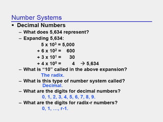
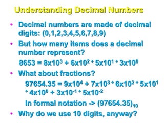
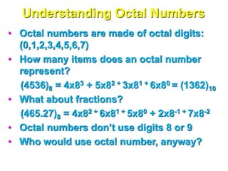
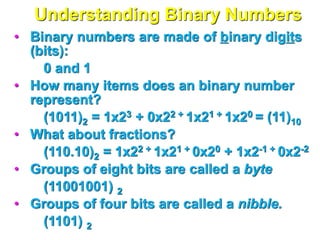
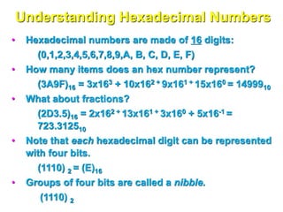
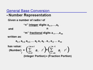
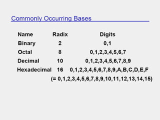
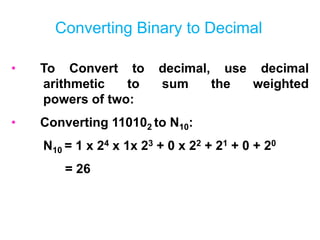
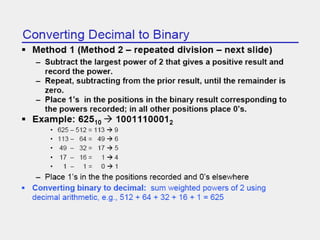
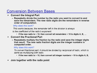
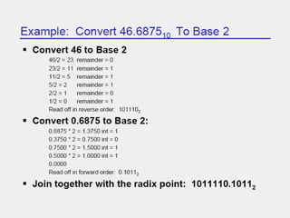
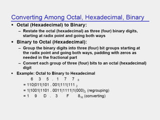
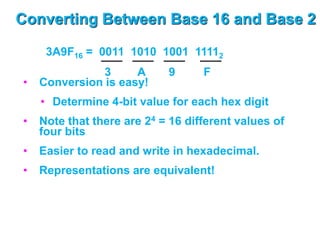
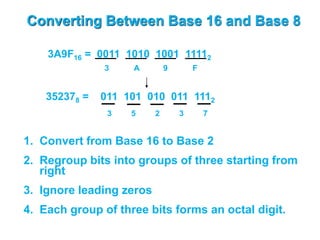
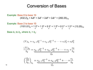
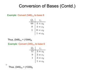
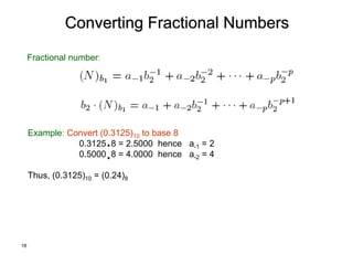
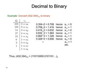
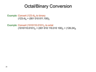
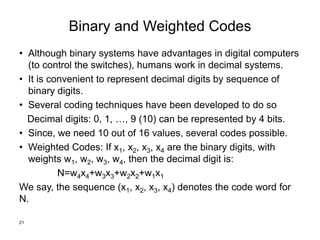
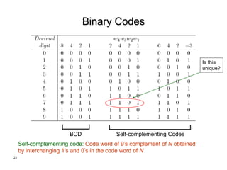
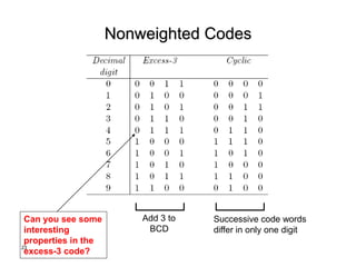
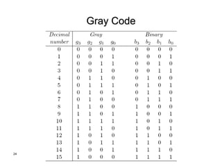
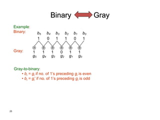
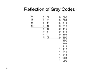
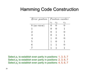
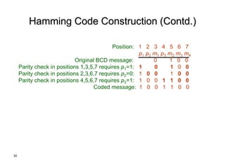
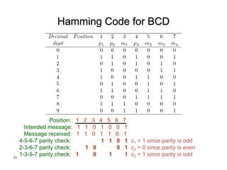
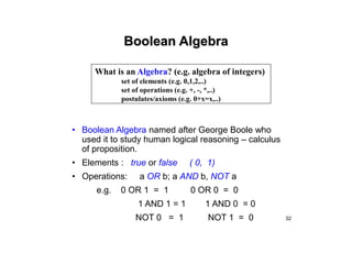
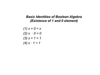
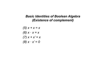
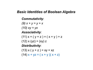
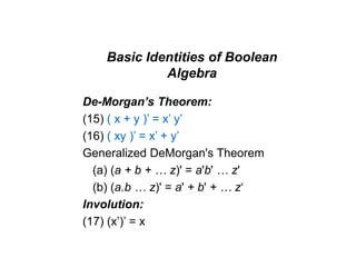
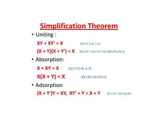
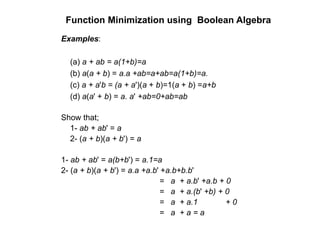
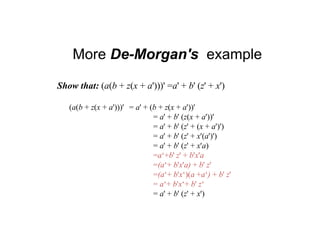
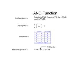
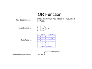
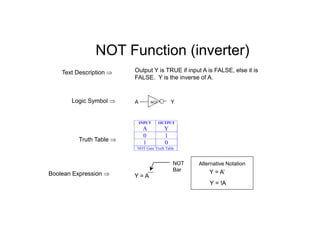
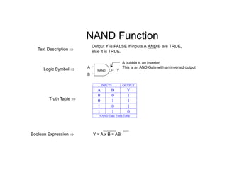
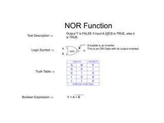
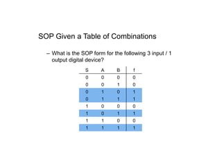
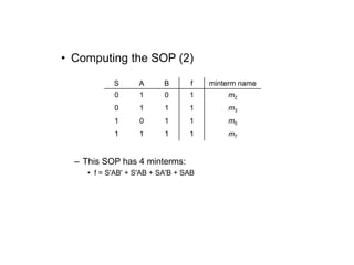
PART –l
Number Systems &
Boolean Algebra
Understanding Decimal Numbers
• Decimal numbers are made of decimal
digits: (0,1,2,3,4,5,6,7,8,9)
• But how many items does a decimal
number represent?
8653 = 8x10³ + 6x10² + 5x101 + 3x100
• What about fractions?
97654.35 = 9x10⁴ + 7x10³ + 6x10² + 5x101
+ 4x100 + 3x10⁻¹ + 5x10⁻²
In formal notation -> (97654.35)10
• Why do we use 10 digits, anyway?
Understanding Octal Numbers
• Octal numbers are made of octal digits:
(0,1,2,3,4,5,6,7)
• How many items does an octal number
represent?
(4536)8 = 4x83 + 5x82 + 3x81 + 6x80 = (1362)10
• What about fractions?
(465.27)8 = 4x82 + 6x81 + 5x80 + 2x8-1 + 7x8-2
• Octal numbers don’t use digits 8 or 9
• Who would use octal number, anyway?
Understanding Binary Numbers
• Binary numbers are made of binary digits
(bits):
0 and 1
• How many items does an binary number
represent?
(1011)2 = 1x23 + 0x22 + 1x21 + 1x20 = (11)10
• What about fractions?
(110.10)2 = 1x22 + 1x21 + 0x20 + 1x2-1 + 0x2-2
• Groups of eight bits are called a byte
(11001001) 2
• Groups of four bits are called a nibble.
(1101) 2
Understanding Hexadecimal Numbers
• Hexadecimal numbers are made of 16 digits:
(0,1,2,3,4,5,6,7,8,9,A, B, C, D, E, F)
• How many items does an hex number represent?
(3A9F)16 = 3x163 + 10x162 + 9x161 + 15x160 = 1499910
• What about fractions?
(2D3.5)16 = 2x162 + 13x161 + 3x160 + 5x16-1 =
723.312510
• Note that each hexadecimal digit can be represented
with four bits.
(1110) 2 = (E)16
• Groups of four bits are called a nibble.
(1110) 2
Converting Binary to Decimal
• To Convert to decimal, use decimal
arithmetic to sum the weighted
powers of two:
• Converting 110102 to N10:
N10 = 1 x 24 x 1x 23 + 0 x 22 + 21 + 0 + 20
= 26
Converting Between Base 16 and Base 2
• Conversion is easy!
• Determine 4-bit value for each hex digit
• Note that there are 24 = 16 different values of
four bits
• Easier to read and write in hexadecimal.
• Representations are equivalent!
3A9F16 = 0011 1010 1001 11112
3 A 9 F
Converting Between Base 16 and Base 8
1. Convert from Base 16 to Base 2
2. Regroup bits into groups of three starting from
right
3. Ignore leading zeros
4. Each group of three bits forms an octal digit.
3A9F16 = 0011 1010 1001 11112
3 A 9 F
352378 = 011 101 010 011 1112
5 2 3 7
3
16
Conversion of Bases
Example: Base 8 to base 10
(432.2)8 = 4 82 + 3 81 + 2 80 + 2 8-1 = (282.25)10
Example: Base 2 to base 10
(1101.01)2 = 1 23 + 1 22 + 0 21 + 1 20 + 0 2-1 + 1 2-2 = (13.25)10
Base b1 to b2, where b1 > b2:
17
Conversion of Bases (Contd.)
Example: Convert (548)10 to base 8
Thus, (548)10 = (1044)8
Thus, (345)10 = (1333)6
Example: Convert (345)10 to base 6
18
Converting Fractional Numbers
Fractional number:
Example: Convert (0.3125)10 to base 8
0.3125 8 = 2.5000 hence a-1 = 2
0.5000 8 = 4.0000 hence a-2 = 4
Thus, (0.3125)10 = (0.24)8
19
Decimal to Binary
Example: Convert (432.354)10 to binary
0.354 2 = 0.708 hence a-1 = 0
0.708 2 = 1.416 hence a-2 = 1
0.416 2 = 0.832 hence a-3 = 0
0.832 2 = 1.664 hence a-4 = 1
0.664 2 = 1.328 hence a-5 = 1
0.328 2 = 0.656 hence a-6 = 0
a-7 = 1
etc.
Thus, (432.354)10 = (110110000.0101101…)2
20
Octal/Binary Conversion
Example: Convert (123.4)8 to binary
(123.4)8 = (001 010 011.100)2
Example: Convert (1010110.0101)2 to octal
(1010110.0101)2 = (001 010 110.010 100)2 = (126.24)8
Binary and Weighted Codes
• Although binary systems have advantages in digital computers
(to control the switches), humans work in decimal systems.
• It is convenient to represent decimal digits by sequence of
binary digits.
• Several coding techniques have been developed to do so
Decimal digits: 0, 1, …, 9 (10) can be represented by 4 bits.
• Since, we need 10 out of 16 values, several codes possible.
• Weighted Codes: If x1, x2, x3, x4 are the binary digits, with
weights w1, w2, w3, w4, then the decimal digit is:
N=w4x4+w3x3+w2x2+w1x1
We say, the sequence (x1, x2, x3, x4) denotes the code word for
N.
21
22
Binary Codes
BCD
Self-complementing code: Code word of 9’s complement of N obtained
by interchanging 1’s and 0’s in the code word of N
Self-complementing Codes
Is this
unique?
23
Nonweighted Codes
Add 3 to
BCD
Successive code words
differ in only one digit
Can you see some
interesting
properties in the
excess-3 code?
24
Gray Code
25
Binary Gray
Example:
Binary:
Gray:
Gray-to-binary:
• bi = gi if no. of 1’s preceding gi is even
• bi = gi’ if no. of 1’s preceding gi is odd
+ +
+
+
+ +
1 0 1
1 1
0
1 1 1 0 1 1
g5 g4 g3 g2 g1 g0
b5 b4 b3 b2 b1 b0
26
Reflection of Gray Codes
00
01
11
10
0
0
0
0
1
1
1
1
10
11
01
00
00
01
11
10
0
0
0
0
0
0
0
0
000
001
011
010
110
111
101
100
1
1
1
1
1
1
1
1
100
101
111
110
010
011
001
000
27
Hamming Codes: Single Error-correcting
Minimum distance for SEC or double-error detecting (DED) codes = 3
Example: {000,111}
Minimum distance for SEC and DED codes = 4
No. of information bits = m
No. of parity check bits, p1, p2, …, pk = k
No. of bits in the code word = m+k
Assign a decimal value to each of the m+k bits: from 1 to MSB to m+k to
LSB
Perform k parity checks on selected bits of each code word: record results
as 0 or 1
• Form a binary number (called position number), c1c2…ck, with the k
parity checks
28
Hamming Codes (Contd.)
No. of parity check bits, k, must satisfy: 2k >= m+k+1
Example: if m = 4 then k =3
Place check bits at the following locations: 1, 2, 4, …, 2k-1
Example code word: 1100110
• Check bits: p1= 1, p2 = 1, p3 = 0
• Information bits: 0, 1, 1, 0
29
Hamming Code Construction
Select p1 to establish even parity in positions: 1, 3, 5, 7
Select p2 to establish even parity in positions: 2, 3, 6, 7
Select p3 to establish even parity in positions: 4, 5, 6, 7
30
Hamming Code Construction (Contd.)
Position: 1 2 3 4 5 6 7
p1 p2 m1 p3 m2 m3 m4
Original BCD message: 0 1 0 0
Parity check in positions 1,3,5,7 requires p1=1: 1 0 1 0 0
Parity check in positions 2,3,6,7 requires p2=0: 1 0 0 1 0 0
Parity check in positions 4,5,6,7 requires p3=1: 1 0 0 1 1 0 0
Coded message: 1 0 0 1 1 0 0
31
Hamming Code for BCD
Position: 1 2 3 4 5 6 7
Intended message: 1 1 0 1 0 0 1
Message received: 1 1 0 1 1 0 1
4-5-6-7 parity check: 1 1 0 1 c1 = 1 since parity is odd
2-3-6-7 parity check: 1 0 0 1 c2 = 0 since parity is even
1-3-5-7 parity check: 1 0 1 1 c3 = 1 since parity is odd
32
Boolean Algebra
• Boolean Algebra named after George Boole who
used it to study human logical reasoning – calculus
of proposition.
• Elements : true or false ( 0, 1)
• Operations: a OR b; a AND b, NOT a
e.g. 0 OR 1 = 1 0 OR 0 = 0
1 AND 1 = 1 1 AND 0 = 0
NOT 0 = 1 NOT 1 = 0
What is an Algebra? (e.g. algebra of integers)
set of elements (e.g. 0,1,2,..)
set of operations (e.g. +, -, *,..)
postulates/axioms (e.g. 0+x=x,..)
Boolean function
• Boolean function: Mapping from Boolean
variables to a Boolean value.
• Boolean algebra: Deals with binary variables and
logic operations operating on those variables.
Basic Identities of Boolean Algebra
(Existence of 1 and 0 element)
(1) x + 0 = x
(2) x · 0 = 0
(3) x + 1 = 1
(4) x · 1 = 1
Basic Identities of Boolean Algebra
(Existence of complement)
(5) x + x = x
(6) x · x = x
(7) x + x’ = x
(8) x · x’ = 0
Basic Identities of Boolean Algebra
Commutativity:
(9) x + y = y + x
(10) xy = yx
Associativity:
(11) x + ( y + z ) = ( x + y ) + z
(12) x (yz) = (xy) z
Distributivity:
(13) x ( y + z ) = xy + xz
(14) x + yz = ( x + y )( x + z)
Basic Identities of Boolean
Algebra
De-Morgan’s Theorem:
(15) ( x + y )’ = x’ y’
(16) ( xy )’ = x’ + y’
Generalized DeMorgan's Theorem
(a) (a + b + … z)' = a'b' … z'
(b) (a.b … z)' = a' + b' + … z‘
Involution:
(17) (x’)’ = x
Function Minimization using Boolean Algebra
Examples:
(a) a + ab = a(1+b)=a
(b) a(a + b) = a.a +ab=a+ab=a(1+b)=a.
(c) a + a'b = (a + a')(a + b)=1(a + b) =a+b
(d) a(a' + b) = a. a' +ab=0+ab=ab
Show that;
1- ab + ab' = a
2- (a + b)(a + b') = a
1- ab + ab' = a(b+b') = a.1=a
2- (a + b)(a + b') = a.a +a.b' +a.b+b.b'
= a + a.b' +a.b + 0
= a + a.(b' +b) + 0
= a + a.1 + 0
= a + a = a
More De-Morgan's example
Show that: (a(b + z(x + a')))' =a' + b' (z' + x')
(a(b + z(x + a')))' = a' + (b + z(x + a'))'
= a' + b' (z(x + a'))'
= a' + b' (z' + (x + a')')
= a' + b' (z' + x'(a')')
= a' + b' (z' + x'a)
=a‘+b' z' + b'x'a
=(a‘+ b'x'a) + b' z'
=(a‘+ b'x‘)(a +a‘) + b' z'
= a‘+ b'x‘+ b' z‘
= a' + b' (z' + x')
Logic Gates
AND Function
Output Y is TRUE if inputs A AND B are TRUE,
else it is FALSE.
Logic Symbol 
Text Description 
Truth Table 
Boolean Expression 
AND
A
B
Y
INPUTS OUTPUT
A B Y
0 0 0
0 1 0
1 0 0
1 1 1
AND Gate Truth Table
Y = A x B = A • B = AB
AND Symbol
OR Function
Output Y is TRUE if input A OR B is TRUE, else it
is FALSE.
Logic Symbol 
Text Description 
Truth Table 
Boolean Expression  Y = A + B
OR Symbol
A
B
Y
OR
INPUTS OUTPUT
A B Y
0 0 0
0 1 1
1 0 1
1 1 1
OR Gate Truth Table
NOT Function (inverter)
Output Y is TRUE if input A is FALSE, else it is
FALSE. Y is the inverse of A.
Logic Symbol 
Text Description 
Truth Table 
Boolean Expression 
INPUT OUTPUT
A Y
0 1
1 0
NOT Gate Truth Table
A Y
NOT
NOT
Bar
Y = A
Y = A’
Alternative Notation
Y = !A
NAND Function
Output Y is FALSE if inputs A AND B are TRUE,
else it is TRUE.
Logic Symbol 
Text Description 
Truth Table 
Boolean Expression 
A
B
Y
NAND
A bubble is an inverter
This is an AND Gate with an inverted output
Y = A x B = AB
INPUTS OUTPUT
A B Y
0 0 1
0 1 1
1 0 1
1 1 0
NAND Gate Truth Table
NOR Function
Output Y is FALSE if input A OR B is TRUE, else it
is TRUE.
Logic Symbol 
Text Description 
Truth Table 
Boolean Expression  Y = A + B
A
B
Y
NOR
A bubble is an inverter.
This is an OR Gate with its output inverted.
INPUTS OUTPUT
A B Y
0 0 1
0 1 0
1 0 0
1 1 0
NOR Gate Truth Table
SOP Given a Table of Combinations
– What is the SOP form for the following 3 input / 1
output digital device?
S A B f
0 0 0 0
0 0 1 0
0 1 0 1
0 1 1 1
1 0 0 0
1 0 1 1
1 1 0 0
1 1 1 1
• Computing the SOP (2)
– This SOP has 4 minterms:
• f = S'AB' + S'AB + SA'B + SAB
S A B f minterm name
0 1 0 1 m2
0 1 1 1 m3
1 0 1 1 m5
1 1 1 1 m7
• Canonical SOP
– Boolean functions can use shorthand notation when
in SOP form:
• f = S'AB' + S'AB + SA'B + SAB
f(S,A,B) = (m2,m3,m5,m7)
or
f(S,A,B) = m(2,3,5,7)
• Canonical SOP Example
– f(x1,x2,x3) = m(1,4,5,6)
– f =
minterm x1 x2 x3 f
0 0 0 0 0
1 0 0 1 1
2 0 1 0 0
3 0 1 1 0
4 1 0 0 1
5 1 0 1 1
6 1 1 0 1
7 1 1 1 0
x1'x2'x3 + x1x2'x3' + x1x2'x3 + x1x2x3'
• Product of Sums Form
– An alternate canonical “two-level” format
• “Product of sums”  POS
• Two levels
– OR level followed by AND level
– Again, NOT doesn’t count as a level
• Not a common as SOP, but can be useful in some situations
– Which ones?
• Computing the POS
– Identify rows with “0” on output (f = 0)
– Represent the input for each 0 row as a maxterm
• A logical “sum” of the input bits which guarantees that term
will be “0” (sum of literals)
A B f
0 0 0
0 1 1
1 0 0
1 1 0
• Canonical POS Example
– f(x1,x2,x3) = (M0,M2,M3,M7) = M(0,2,3,7)
– f =
maxterm x1 x2 x3 f
0 0 0 0 0
1 0 0 1 1
2 0 1 0 0
3 0 1 1 0
4 1 0 0 1
5 1 0 1 1
6 1 1 0 1
7 1 1 1 0
(x1+x2+x3)(x1+x2'+x3)(x1+x2'+x3')(x1'+x2'+x3')
Terminology/Definition
• Literal
– A variable or its complement
• Logically adjacent terms
– Two minterms are logically adjacent if
they differ in only one variable position
– Ex:
abc abc
and
m6 and m2 are logically adjacent
Note:  
abc abc a a bc bc
   
Or, logically adjacent terms can be combined
Terminology/Definition
• Implicant
– Product term that could be used to cover minterms of
a function
• Prime Implicant
– An implicant that is not part of another implicant
• Essential Prime Implicant
– An implicant that covers at least one minterm that is
not contained in another prime implicant
• Cover
– A minterm that has been used in at least one group
Guidelines for Simplifying Functions
• Each square on a K-map of n
variables has n logically adjacent
squares. (i.e. differing in exactly one
variable)
• When combing squares, always
group in powers of 2m , where
m=0,1,2,….
• In general, grouping 2m variables
eliminates m variables.
Guidelines for Simplifying Functions
• Group as many squares as possible.
This eliminates the most variables.
• Make as few groups as possible.
Each group represents a separate
product term.
• You must cover each minterm at
least once. However, it may be
covered more than once.
K-map Simplification
Procedure
• Plot the K-map
• Circle all prime implicants on the K-
map
• Identify and select all essential prime
implicants for the cover.
• Select a minimum subset of the
remaining prime implicants to
complete the cover.
• Read the K-map
Example
• Use a K-Map to simplify the following
Boolean expression
   
, , 1, 2,3,5,6
F a b c m
 
Three-Variable K-Map
Example
ab
c 00 01 11 10
0
1
Step 1: Plot the K-map
1 1 1
1
   
, , 1, 2,3,5,6
F a b c m
 
1
Three-Variable K-Map
Example
ab
c 00 01 11 10
0
1
Step 2: Circle ALL Prime Implicants
1 1 1
1
   
, , 1, 2,3,5,6
F a b c m
 
1
Three-Variable K-Map
Example
ab
c 00 01 11 10
0
1
Step 3: Identify Essential Prime Implicants
1 1 1
1
   
, , 1, 2,3,5,6
F a b c m
 
1
EPI
EPI
PI
PI
Three-Variable K-Map
Example
ab
c 00 01 11 10
0
1
Step 4: Select minimum subset of remaining
Prime Implicants to complete the cover.
1 1 1
1
   
, , 1, 2,3,5,6
F a b c m
 
1
EPI
PI
EPI
Three-Variable K-Map
Example
ab
c 00 01 11 10
0
1
Step 5: Read the map.
1 1 1
1
   
, , 1, 2,3,5,6
F a b c m
 
1
bc
ab
bc
Solution
 
, ,
F a b c ab bc bc ab b c
     
Example
• Use a K-Map to simplify the following
Boolean expression
   
, , 2,3,6,7
F a b c m
 
Three-Variable K-Map
Example
ab
c 00 01 11 10
0
1
Step 1: Plot the K-map
1
1
1
1
   
, , 2, 4,5,7
F a b c m
 
Three-Variable K-Map
Example
ab
c 00 01 11 10
0
1
Step 2: Circle Prime Implicants
1
1
1
1
   
, , 2,3,6,7
F a b c m
 
Wrong!!
We really
should draw
A circle around
all four 1’s
Three-Variable K-Map
Example
ab
c 00 01 11 10
0
1
Step 3: Identify Essential Prime Implicants
EPI
EPI
   
, , 2,3,6,7
F a b c m
 
1
1
1
1
Wrong!!
We really
should draw
A circle around
all four 1’s
Three-Variable K-Map
Example
ab
c 00 01 11 10
0
1
Step 4: Select Remaining Prime Implicants to
complete the cover.
EPI
EPI
1
1
1
1
   
, , 2,3,6,7
F a b c m
 
Three-Variable K-Map
Example
ab
c 00 01 11 10
0
1
Step 5: Read the map.
ab
ab
1
1
1
1
   
, , 2,3,6,7
F a b c m
 
Solution
 
, ,
F a b c ab ab b
  
Since we can still simplify the function
this means we did not use the largest
possible groupings.
Three-Variable K-Map
Example
ab
c 00 01 11 10
0
1
Step 2: Circle Prime Implicants
1
1
1
1
   
, , 2,3,6,7
F a b c m
 
Right!
Three-Variable K-Map
Example
ab
c 00 01 11 10
0
1
Step 3: Identify Essential Prime Implicants
EPI
   
, , 2,3,6,7
F a b c m
 
1
1
1
1
Three-Variable K-Map
Example
ab
c 00 01 11 10
0
1
Step 5: Read the map.
b
1
1
1
1
   
, , 2,3,6,7
F a b c m
 
Solution
 
, ,
F a b c b

Three-Variable K-Map
Example
ab
c 00 01 11 10
0
1 1 1 1
1
 
, , 1
F a b c 
1
1
1
1
Three-Variable K-Map
Example
ab
c 00 01 11 10
0
1 1
 
, ,
F a b c a b c
  
1
1
1
Four Variable Examples
Example
• Use a K-Map to simplify the following
Boolean expression
   
, , , 0, 2,3,6,8,12,13,15
F a b c d m
 
Four-variable K-Map
ab
cd 00 01 11 10
00
01
11
10
   
, , , 0, 2,3,6,8,12,13,15
F a b c d m
 
1
1
1
1
1
1
1
1
Four-variable K-Map
ab
cd 00 01 11 10
00
01
11
10
 
0, 2,3,6,8,12,13,15
F m
 
1
1
1
1
1
1
1
1
Four-variable K-Map
ab
cd 00 01 11 10
00
01
11
10
F abd abc acd abd acd
    
1
1
1
1
1
1
1
1
Example
• Use a K-Map to simplify the following
Boolean expression
   
 
, , , 0,2,6,8,12,13,15
3,9,10
F a b c d m
d



D=Don’t care (i.e. either 1 or 0)
Four-variable K-Map
ab
cd 00 01 11 10
00
01
11
10
1
1
d
1
1
1
1
1
     
, , , 0, 2,6,8,12,13,15 3, 4,9
F a b c d m d
 

d
d
Four-variable K-Map
ab
cd 00 01 11 10
00
01
11
10
1
1
d
1
1
1
1
1
F ac ad abd
  
d
d
KARNAUGH MAP
Karnaugh Map for an n-input digital logic circuit (n-variable sum-of-products
form of Boolean Function, or Truth Table) is
- Rectangle divided into 2n cells
- Each cell is associated with a Minterm
- An output(function) value for each input value associated with a
mintern is written in the cell representing the minterm
→ 1-cell, 0-cell
Each Minterm is identified by a decimal number whose binary representation
is identical to the binary interpretation of the input values of the minterm.
x F
0 1
1 0
x
0
1
0
1
x
0
1
0
1
Karnaugh Map
value
of F
Identification
of the cell
x y F
0 0 0
0 1 1
1 0 1
1 1 1
y
x 0 1
0
1
0 1
2 3
y
x 0 1
0
1
0 1
1 0
F(x) =
F(x,y) =  (1,2)
1-cell
 (1)
Map Simplification
KARNAUGH MAP
0 0 0 0
0 0 1 1
0 1 0 1
0 1 1 0
1 0 0 1
1 0 1 0
1 1 0 0
1 1 1 0
0 1 0 1
1 0 0 0
0 0 0 0 0
0 0 0 1 1
0 0 1 0 0
0 0 1 1 1
0 1 0 0 0
0 1 0 1 0
0 1 1 0 1
0 1 1 1 0
1 0 0 0 1
1 0 0 1 1
1 0 1 0 0
1 0 1 1 1
1 1 0 0 0
1 1 0 1 0
1 1 1 0 1
1 1 1 1 0
x
yz
00 01 11 10
0 0 1 3 2
4 5 7 6
x
yz
00 01 11 10
0
1
F(x,y,z) =  (1,2,4)
1
x
y
z
uv
wx
00 01 11 10
00
01
11
10
0 1 3 2
4 5 7 6
12 13 15 14
8 9 11 10
uv
wx
00 01 11 10
00
01
11 0 0 0 1
10 1 1 1 0
0 1 1 0
0 0 0 1
F(u,v,w,x) =  (1,3,6,8,9,11,14)
u
v
w
x
Map Simplification
x y z F
u v w x F
MAP SIMPLIFICATION - 2
ADJACENT CELLS -
Adjacent cells
- binary identifications are different in one bit
→ minterms associated with the adjacent
cells have one variable complemented each other
Cells (1,0) and (1,1) are adjacent
Minterms for (1,0) and (1,1) are
x • y’ --> x=1, y=0
x • y --> x=1, y=1
F = xy’+ xy can be reduced to F = x
From the map
Rule: xy’ +xy = x(y+y’) = x
x
y
0 1
0
1 1 1
0 0
 (2,3)
F(x,y) =
2 adjacent cells xy’ and xy
→ merge them to a larger cell x
= xy’+ xy
= x
Map Simplification
MAP SIMPLIFICATION - MORE
THAN 2 CELLS -
u’v’w’x’ + u’v’w’x + u’v’wx + u’v’wx’
= u’v’w’(x’+x) + u’v’w(x+x’)
= u’v’w’ + u’v’w
= u’v’(w’+w)
= u’v’
uv
wx
1 1 1 1
1 1
1 1
uv
wx
1 1 1 1
1 1
1 1
u
v
w
x
u
v
w
x
u’v’
uw
u’x’
v’x
1 1
1 1
vw’
u’v’w’x’+u’v’w’x+u’vw’x’+u’vw’x+uvw’x’+uvw’x+uv’w’x’+uv’w’x
= u’v’w’(x’+x) + u’vw’(x’+x) + uvw’(x’+x) + uv’w’(x’+x)
= u’(v’+v)w’ + u(v’+v)w’
= (u’+u)w’ = w’
Map Simplification
u
v
w
x
uv
wx
1 1
1 1
1 1
1 1
u
v
uv
1 1
1 1
1 1
1 1
1 1 1 1
x
w’
u
V’
w
MAP SIMPLIFICATION
(0,1), (0,2), (0,4), (0,8)
Adjacent Cells of 1
Adjacent Cells of 0
(1,0), (1,3), (1,5), (1,9)
...
...
Adjacent Cells of 15
(15,7), (15,11), (15,13), (15,14)
uv
wx
00 01 11 10
00
01 0 0 0 0
11 0 1 1 0
10 0 1 0 0
1 1 0 1
F(u,v,w,x) =  (0,1,2,9,13,15)
u
v
w
x
Merge (0,1) and (0,2)
--> u’v’w’ + u’v’x’
Merge (1,9)
--> v’w’x
Merge (9,13)
--> uw’x
Merge (13,15)
--> uvx
F = u’v’w’ + u’v’x’ + v’w’x + uw’x + uvx
But (9,13) is covered by (1,9) and (13,15)
F = u’v’w’ + u’v’x’ + v’w’x + uvx
Map Simplification
0 0 0 0
1 1 0 1
0 1 1 0
0 1 0 0
IMPLEMENTATION OF K-MAPS - Sum-of-Products Form -
Logic function represented by a Karnaugh map
can be implemented in the form of I-AND-OR
A cell or a collection of the adjacent 1-cells can
be realized by an AND gate, with some inversion of the input variables.
x
y
z
x’
y’
z’
x’
y
z’
x
y
z’
1 1
1
F(x,y,z) =  (0,2,6)
1 1
1
x’
z’
y
z’
Map Simplification

x’
y
x
y
z’
x’
y’
z’
F
x
z
y
z
F
I AND OR
z’

IMPLEMENTATION OF K-MAPS - Product-of-Sums Form -
Logic function represented by a Karnaugh map
can be implemented in the form of I-OR-AND
If we implement a Karnaugh map using 0-cells,
the complement of F, i.e., F’, can be obtained.
Thus, by complementing F’ using DeMorgan’s
theorem F can be obtained
F(x,y,z) = (0,2,6)
x
y
z
x
y’
z
F’ = xy’ + z
F = (xy’)z’
= (x’ + y)z’
x
y
z
F
I OR AND
Map Simplification
0 0
1 1
0 0 0 1
IMPLEMENTATION OF K-MAPS
- Don’t-Care Conditions -
In some logic circuits, the output responses
for some input conditions are don’t care
whether they are 1 or 0.
In K-maps, don’t-care conditions are represented
by d’s in the corresponding cells.
Don’t-care conditions are useful in minimizing
the logic functions using K-map.
- Can be considered either 1 or 0
- Thus increases the chances of merging cells into the larger cells
--> Reduce the number of variables in the product terms
x
y
z
1 d d 1
d 1
x’
yz’
x
y
z
F
Map Simplification
PART - 2
Combinational Circuits
Adding Two 1-bit Numbers
 Let us add two 1 bit numbers : a and b
 0 + 0 = 00
 1 + 0 = 01
 0 + 1 = 01
 1 + 1 = 10
 The lsb of the result is known, as the sum,
and the msb is known as the carry
Sum and Carry
a
a
a
b
carry sum
Truth Table
a b s c
0 0 0 0
0 1 1 0
1 0 1 0
1 1 0 1
c = a.b
Half Adder
 Adds two 1 bit numbers to produce a 2 bit
result
a
b
a
b
C
S
Half
adder
a
b
S
C
1-Bit Half Adder
Half adder
 0 + 0 = 0 ; 0 + 1 = 1 ; 1 + 0 = 1 ; 1 + 1 =
 two input variables: x, y
(10)2
 two output variables: C (carry), S (sum)
 truth table
S = x'y+xy'=xy=
C = xy= (x'+y')'
S' = xy+x'y'
S = (C+x'y')'
(x+y)(x'+y')
Logic Diagram of 1-Bit
Half Adder
Full Adder
Add three 1 bit numbers to produce a 2 bit output
a b cin s cout
0 0 0 0 0
0 1 0 1 0
1 0 0 1 0
1 1 0 0 1
0 0 1 1 0
0 1 1 0 1
1 0 1 0 1
1 1 1 1 1
Equations for the Full Adder
Circuit for the Full Adder
a
b
a
b
Full
adder
a
b
S
a
b
cin
cin
cout
cin
s
cin
c out
Lan-Da Van DCD-
1-Bit Full Adder
Full-Adder
The arithmetic sum of three
input bits
three input bits
 x, y: two significant bits
 z: the carry bit from the
previous lower significant bit


Two output bits: C, S

Sum Carry
Logic Diagram of 1-Bit
Full Adder
Logic Diagram of 1-Bit
Full Adder
 S = x'y'z+x'yz'+ xy'z'+xyz
= x’(yz) +x(yz)’ = xyz
 C = xy + xz + yz
= xy + xyz + xy’z + xyz + x’yz
= xy + z (xy + xy)
= xy + z (xy)
Addition of two n bit numbers
 We start from the lsb
 Add the corresponding pair of bits and the carry in
 Produce a sum bit and a carry out
1 0 1 1
0 1 0 1
1 0 0 0 0
1
1 1
1
Example: Subtract binary number 101 from 1011
BINARY SUBTRACTION
1 0 1 1
- 1 0 1
(borrow)
0
1
1
0
1
0
Subtract binary number 11 from 1010
TEST
1 0 1 0
- 1 1
1
1
1
0
1
10
0 0
01
1
Subtracts LSD column in binary subtraction
HALF SUBTRACTOR
A
B
Di (difference)
B0 (borrow out)
Half
Subtractor
Input Output
Logic
Symbol:
Logic
Diagram:
Half Subtractor
C
A B D
0 0 0 1
0 0 0 0
0 1 1 1
1 0 1 0
1 1 0 0
A0
B0
D
0
C1
0
-1
1
2
1
Used for subtracting binary place
values other than the 1s place
FULL SUBTRACTOR
Logic
Symbol:
Logic
Diagram:
A
B
Di (difference)
B0 (borrow out)
Full
Subtractor
Input Output
Bin
A
B
Di
B0
H. S.
H. S.
Bin
Full Subtractor
0 0 0 0 0
0 0 1 1 1
0 1 0 1 0
0 1 1 0 0
1 0 0 1 1
1 0 1 0 1
1 1 0 0 0
1 1 1 1 1
Ci Ai Bi Di Ci+1
1 1
1 1
Ci
AiBi
00 01 11 10
0
1
Di
Di = Ci (Ai  Bi)
Same as Si in full adder
Full Subtractor
0 0 0 0 0
0 0 1 1 1
0 1 0 1 0
0 1 1 0 0
1 0 0 1 1
1 0 1 0 1
1 1 0 0 0
1 1 1 1 1
Ci Ai Bi Di Ci+1 Ci
AiBi
00 01 11 10
0
1
1
1 1
1
Ci+1
Ci+1 = !Ai & Bi
# Ci & !Ai & !Bi
# Ci & Ai & Bi
Full Subtractor
Ci+1 = !Ai & Bi
# Ci & !Ai & !Bi
# Ci & Ai & Bi
Ci+1 = !Ai & Bi
# Ci & (!Ai & !Bi # Ai  Bi)
Ci+1 = !Ai & Bi # Ci & !(Ai  Bi)
Recall:
Di = Ci  (Ai  Bi)
Ci+1 = !Ai & Bi # Ci & !(Ai  Bi)
Full Subtractor
A
B
D
C
C i+
1
i
i
i
i
Di = Ci $ (Ai $ Bi)
Ci+1 = !Ai & Bi # Ci & !(Ai $ Bi)
half subtractor
half subtractor
BCD to Excess-3 Code
Conversion
BCD to Excess-3 Code
Conversion
BCD to Excess-3 Code
Conversion
Simplified functions
Z
Y
X
W
=
=
=
D'
CD +C'D'
B'C + B'D+BC'D'
= A+BC+BD
Decoder
An n-to-m decoder
n
 a binary code of n bits = 2 distinct information
 n input variables; up to 2 output lines
n
 only one output can be active (high) at any time
Three-to-Eight Line Decoder
x’y’z’
Decoder with Enable
/Demultiplexer
Demultiplexers
 a decoder with an enable input
 receive information on a single line and transmits it on one of
n
2 possible output lines
0
Two-to-four-line decoder with enable input
Decoder with Enable
/Demultiplexer
4x16 Decoder
Expansion
 two 3-to-8 decoder: a 4-to-16 decoder
4  16 decoder
constructed with
3  8 decoders
two
Combinational Logic
Implementation
Each output = a minterm
Use a decoder and an external OR gate to implement any
Boolean function of
A full-adder
 S(x,y,x)=(1,2,4,7)
 C(x,y,z)= (3,5,6,7)
n input variables
Lan
Encoder
with three OR gates.
The encoder can be implemented
z  D1  D3  D5  D7
y  D2  D3  D6  D7
x  D4  D5  D6  D7
Encoder
An implementation
x=D4+D5+D6+D
7
y=D2+D3+D6+D
7
z=D1+D3+D5+D
7
 limitations
 illegal input: e.g. D3=D6=1
 the output = 111 (¹3 and ¹6)
Priority Encoder
 Resolve the ambiguity of illegal inputs
 Only one of the input is encoded
LSB MSB
 D3 has the highest priority
the lowest priority
 D0 has
 X: don't-care conditions
 V: valid output indicator
Priority Encoder
1
Priority Encoder
x  D2  D3
y  D3  D1D2
V  D0  D1  D2  D3
Multiplexer
Select binary information from one of many input
lines and direct it to a single output line
n
2 input lines, n selection lines and one output line
E.g.: 2-to-1-line multiplexer
Two-to-one-line multiplexer
4-to-1-Line Multiplexer
Boolean Function
Implementation Using MUX
MUX: a decoder + an OR gate
2 -to-1 MUX can implement any Boolean function of n
input variable.
Procedure:
 assign an ordering sequence of the input variable
 the rightmost variable (D) will be used for the input lines
 assign the remaining n-1 variables to the selection lines w.r.t.
their corresponding sequence
 construct the truth table
n
 consider a pair of consecutive
 determine the input lines
minterms starting from m0
Boolean Function
Implementation Using MUX
Example: Given F(x,y,z) = (1,2,6,7)
Boolean Function
Implementation Using MUX
Example: Given F(A, B, C, D) = (1, 3, 4, 11, 12, 13, 14, 15)
MULTIPLEXER
Combinational Logic Circuits
4-to-1 Multiplexer
I0
I1
I2
I3
S0
S1
Y
0 0 I0
0 1 I1
1 0 I2
1 1 I3
Select Output
S1 S0 Y
ENCODER/DECODER
Octal-to-Binary Encoder
Combinational Logic Circuits
D1
D2
D3
D5
D6
D7
D4
A0
A1
A2
A0
A1
E
D0
D1
D2
D3
0 0 0 0 1 1 1
0 0 1 1 0 1 1
0 1 0 1 1 0 1
0 1 1 1 1 1 0
1 d d 1 1 1 1
E A1 A0 D0 D1 D2 D3
2-to-4 Decoder
FLIP FLOPS
Characteristics
- 2 stable states
- Memory capability
- Operation is specified by a Characteristic Table
0-state 1-state
In order to be used in the computer circuits, state of the flip flop should
have input terminals and output terminals so that it can be set to a certain
state, and its state can be read externally.
R
S
Q
Q’
S R Q(t+1)
0 0 Q(t)
0 1 0
1 0 1
1 1 indeterminate
(forbidden)
Flip Flops
1 0 0 1
0 1 1 0
CLOCKED FLIP FLOPS
In a large digital system with many flip flops, operations of individual flip flops
are required to be synchronized to a clock pulse. Otherwise,
the operations of the system may be unpredictable.
R
S
Q
Q’
c
(clock)
Flip Flops
S Q
c
R Q’
S Q
c
R Q’
operates when operates when
clock is high clock is low
Clock pulse allows the flip flop to change state only
when there is a clock pulse appearing at the c terminal.
We call above flip flop a Clocked RS Latch, and symbolically as
D-LATCH
D-Latch
Forbidden input values are forced not to occur
by using an inverter between the inputs
Flip Flops
Q
Q’
D(data)
E
(enable)
D Q
E Q’
E Q’
D Q
D Q(t+1)
0 0
1 1
EDGE-TRIGGERED FLIP
FLOPS
Characteristics
- State transition occurs at the rising edge or
falling edge of the clock pulse
Latches
Edge-triggered Flip Flops (positive)
respond to the input only during these periods
respond to the input only at this time
Flip Flops
POSITIVE EDGE-TRIGGERED
T-Flip Flop: JK-Flip Flop whose J and K inputs are tied together to make
T input. Toggles whenever there is a pulse on T input.
Flip Flops
D-Flip Flop
JK-Flip Flop
S1 Q1
C1
R1 Q1'
S2 Q2
C2
R2 Q2'
D
C
Q
Q'
D
C
Q
Q'
SR1 SR2
SR1 active
SR2 active
D-FF
S1 Q1
C1
R1 Q1'
S2 Q2
C2
R2 Q2'
SR1 SR2
J
K
C
Q
Q'
J Q
C
K Q'
SR1 active
SR2 inactive SR2 inactive
SR1 inactive

UNIT-1_CSA.pdf

  • 1.
    PART –l Number Systems& Boolean Algebra
  • 3.
    Understanding Decimal Numbers •Decimal numbers are made of decimal digits: (0,1,2,3,4,5,6,7,8,9) • But how many items does a decimal number represent? 8653 = 8x10³ + 6x10² + 5x101 + 3x100 • What about fractions? 97654.35 = 9x10⁴ + 7x10³ + 6x10² + 5x101 + 4x100 + 3x10⁻¹ + 5x10⁻² In formal notation -> (97654.35)10 • Why do we use 10 digits, anyway?
  • 4.
    Understanding Octal Numbers •Octal numbers are made of octal digits: (0,1,2,3,4,5,6,7) • How many items does an octal number represent? (4536)8 = 4x83 + 5x82 + 3x81 + 6x80 = (1362)10 • What about fractions? (465.27)8 = 4x82 + 6x81 + 5x80 + 2x8-1 + 7x8-2 • Octal numbers don’t use digits 8 or 9 • Who would use octal number, anyway?
  • 5.
    Understanding Binary Numbers •Binary numbers are made of binary digits (bits): 0 and 1 • How many items does an binary number represent? (1011)2 = 1x23 + 0x22 + 1x21 + 1x20 = (11)10 • What about fractions? (110.10)2 = 1x22 + 1x21 + 0x20 + 1x2-1 + 0x2-2 • Groups of eight bits are called a byte (11001001) 2 • Groups of four bits are called a nibble. (1101) 2
  • 6.
    Understanding Hexadecimal Numbers •Hexadecimal numbers are made of 16 digits: (0,1,2,3,4,5,6,7,8,9,A, B, C, D, E, F) • How many items does an hex number represent? (3A9F)16 = 3x163 + 10x162 + 9x161 + 15x160 = 1499910 • What about fractions? (2D3.5)16 = 2x162 + 13x161 + 3x160 + 5x16-1 = 723.312510 • Note that each hexadecimal digit can be represented with four bits. (1110) 2 = (E)16 • Groups of four bits are called a nibble. (1110) 2
  • 9.
    Converting Binary toDecimal • To Convert to decimal, use decimal arithmetic to sum the weighted powers of two: • Converting 110102 to N10: N10 = 1 x 24 x 1x 23 + 0 x 22 + 21 + 0 + 20 = 26
  • 14.
    Converting Between Base16 and Base 2 • Conversion is easy! • Determine 4-bit value for each hex digit • Note that there are 24 = 16 different values of four bits • Easier to read and write in hexadecimal. • Representations are equivalent! 3A9F16 = 0011 1010 1001 11112 3 A 9 F
  • 15.
    Converting Between Base16 and Base 8 1. Convert from Base 16 to Base 2 2. Regroup bits into groups of three starting from right 3. Ignore leading zeros 4. Each group of three bits forms an octal digit. 3A9F16 = 0011 1010 1001 11112 3 A 9 F 352378 = 011 101 010 011 1112 5 2 3 7 3
  • 16.
    16 Conversion of Bases Example:Base 8 to base 10 (432.2)8 = 4 82 + 3 81 + 2 80 + 2 8-1 = (282.25)10 Example: Base 2 to base 10 (1101.01)2 = 1 23 + 1 22 + 0 21 + 1 20 + 0 2-1 + 1 2-2 = (13.25)10 Base b1 to b2, where b1 > b2:
  • 17.
    17 Conversion of Bases(Contd.) Example: Convert (548)10 to base 8 Thus, (548)10 = (1044)8 Thus, (345)10 = (1333)6 Example: Convert (345)10 to base 6
  • 18.
    18 Converting Fractional Numbers Fractionalnumber: Example: Convert (0.3125)10 to base 8 0.3125 8 = 2.5000 hence a-1 = 2 0.5000 8 = 4.0000 hence a-2 = 4 Thus, (0.3125)10 = (0.24)8
  • 19.
    19 Decimal to Binary Example:Convert (432.354)10 to binary 0.354 2 = 0.708 hence a-1 = 0 0.708 2 = 1.416 hence a-2 = 1 0.416 2 = 0.832 hence a-3 = 0 0.832 2 = 1.664 hence a-4 = 1 0.664 2 = 1.328 hence a-5 = 1 0.328 2 = 0.656 hence a-6 = 0 a-7 = 1 etc. Thus, (432.354)10 = (110110000.0101101…)2
  • 20.
    20 Octal/Binary Conversion Example: Convert(123.4)8 to binary (123.4)8 = (001 010 011.100)2 Example: Convert (1010110.0101)2 to octal (1010110.0101)2 = (001 010 110.010 100)2 = (126.24)8
  • 21.
    Binary and WeightedCodes • Although binary systems have advantages in digital computers (to control the switches), humans work in decimal systems. • It is convenient to represent decimal digits by sequence of binary digits. • Several coding techniques have been developed to do so Decimal digits: 0, 1, …, 9 (10) can be represented by 4 bits. • Since, we need 10 out of 16 values, several codes possible. • Weighted Codes: If x1, x2, x3, x4 are the binary digits, with weights w1, w2, w3, w4, then the decimal digit is: N=w4x4+w3x3+w2x2+w1x1 We say, the sequence (x1, x2, x3, x4) denotes the code word for N. 21
  • 22.
    22 Binary Codes BCD Self-complementing code:Code word of 9’s complement of N obtained by interchanging 1’s and 0’s in the code word of N Self-complementing Codes Is this unique?
  • 23.
    23 Nonweighted Codes Add 3to BCD Successive code words differ in only one digit Can you see some interesting properties in the excess-3 code?
  • 24.
  • 25.
    25 Binary Gray Example: Binary: Gray: Gray-to-binary: • bi= gi if no. of 1’s preceding gi is even • bi = gi’ if no. of 1’s preceding gi is odd + + + + + + 1 0 1 1 1 0 1 1 1 0 1 1 g5 g4 g3 g2 g1 g0 b5 b4 b3 b2 b1 b0
  • 26.
    26 Reflection of GrayCodes 00 01 11 10 0 0 0 0 1 1 1 1 10 11 01 00 00 01 11 10 0 0 0 0 0 0 0 0 000 001 011 010 110 111 101 100 1 1 1 1 1 1 1 1 100 101 111 110 010 011 001 000
  • 27.
    27 Hamming Codes: SingleError-correcting Minimum distance for SEC or double-error detecting (DED) codes = 3 Example: {000,111} Minimum distance for SEC and DED codes = 4 No. of information bits = m No. of parity check bits, p1, p2, …, pk = k No. of bits in the code word = m+k Assign a decimal value to each of the m+k bits: from 1 to MSB to m+k to LSB Perform k parity checks on selected bits of each code word: record results as 0 or 1 • Form a binary number (called position number), c1c2…ck, with the k parity checks
  • 28.
    28 Hamming Codes (Contd.) No.of parity check bits, k, must satisfy: 2k >= m+k+1 Example: if m = 4 then k =3 Place check bits at the following locations: 1, 2, 4, …, 2k-1 Example code word: 1100110 • Check bits: p1= 1, p2 = 1, p3 = 0 • Information bits: 0, 1, 1, 0
  • 29.
    29 Hamming Code Construction Selectp1 to establish even parity in positions: 1, 3, 5, 7 Select p2 to establish even parity in positions: 2, 3, 6, 7 Select p3 to establish even parity in positions: 4, 5, 6, 7
  • 30.
    30 Hamming Code Construction(Contd.) Position: 1 2 3 4 5 6 7 p1 p2 m1 p3 m2 m3 m4 Original BCD message: 0 1 0 0 Parity check in positions 1,3,5,7 requires p1=1: 1 0 1 0 0 Parity check in positions 2,3,6,7 requires p2=0: 1 0 0 1 0 0 Parity check in positions 4,5,6,7 requires p3=1: 1 0 0 1 1 0 0 Coded message: 1 0 0 1 1 0 0
  • 31.
    31 Hamming Code forBCD Position: 1 2 3 4 5 6 7 Intended message: 1 1 0 1 0 0 1 Message received: 1 1 0 1 1 0 1 4-5-6-7 parity check: 1 1 0 1 c1 = 1 since parity is odd 2-3-6-7 parity check: 1 0 0 1 c2 = 0 since parity is even 1-3-5-7 parity check: 1 0 1 1 c3 = 1 since parity is odd
  • 32.
    32 Boolean Algebra • BooleanAlgebra named after George Boole who used it to study human logical reasoning – calculus of proposition. • Elements : true or false ( 0, 1) • Operations: a OR b; a AND b, NOT a e.g. 0 OR 1 = 1 0 OR 0 = 0 1 AND 1 = 1 1 AND 0 = 0 NOT 0 = 1 NOT 1 = 0 What is an Algebra? (e.g. algebra of integers) set of elements (e.g. 0,1,2,..) set of operations (e.g. +, -, *,..) postulates/axioms (e.g. 0+x=x,..)
  • 33.
    Boolean function • Booleanfunction: Mapping from Boolean variables to a Boolean value. • Boolean algebra: Deals with binary variables and logic operations operating on those variables.
  • 34.
    Basic Identities ofBoolean Algebra (Existence of 1 and 0 element) (1) x + 0 = x (2) x · 0 = 0 (3) x + 1 = 1 (4) x · 1 = 1
  • 35.
    Basic Identities ofBoolean Algebra (Existence of complement) (5) x + x = x (6) x · x = x (7) x + x’ = x (8) x · x’ = 0
  • 36.
    Basic Identities ofBoolean Algebra Commutativity: (9) x + y = y + x (10) xy = yx Associativity: (11) x + ( y + z ) = ( x + y ) + z (12) x (yz) = (xy) z Distributivity: (13) x ( y + z ) = xy + xz (14) x + yz = ( x + y )( x + z)
  • 37.
    Basic Identities ofBoolean Algebra De-Morgan’s Theorem: (15) ( x + y )’ = x’ y’ (16) ( xy )’ = x’ + y’ Generalized DeMorgan's Theorem (a) (a + b + … z)' = a'b' … z' (b) (a.b … z)' = a' + b' + … z‘ Involution: (17) (x’)’ = x
  • 39.
    Function Minimization usingBoolean Algebra Examples: (a) a + ab = a(1+b)=a (b) a(a + b) = a.a +ab=a+ab=a(1+b)=a. (c) a + a'b = (a + a')(a + b)=1(a + b) =a+b (d) a(a' + b) = a. a' +ab=0+ab=ab Show that; 1- ab + ab' = a 2- (a + b)(a + b') = a 1- ab + ab' = a(b+b') = a.1=a 2- (a + b)(a + b') = a.a +a.b' +a.b+b.b' = a + a.b' +a.b + 0 = a + a.(b' +b) + 0 = a + a.1 + 0 = a + a = a
  • 40.
    More De-Morgan's example Showthat: (a(b + z(x + a')))' =a' + b' (z' + x') (a(b + z(x + a')))' = a' + (b + z(x + a'))' = a' + b' (z(x + a'))' = a' + b' (z' + (x + a')') = a' + b' (z' + x'(a')') = a' + b' (z' + x'a) =a‘+b' z' + b'x'a =(a‘+ b'x'a) + b' z' =(a‘+ b'x‘)(a +a‘) + b' z' = a‘+ b'x‘+ b' z‘ = a' + b' (z' + x')
  • 41.
  • 42.
    AND Function Output Yis TRUE if inputs A AND B are TRUE, else it is FALSE. Logic Symbol  Text Description  Truth Table  Boolean Expression  AND A B Y INPUTS OUTPUT A B Y 0 0 0 0 1 0 1 0 0 1 1 1 AND Gate Truth Table Y = A x B = A • B = AB AND Symbol
  • 43.
    OR Function Output Yis TRUE if input A OR B is TRUE, else it is FALSE. Logic Symbol  Text Description  Truth Table  Boolean Expression  Y = A + B OR Symbol A B Y OR INPUTS OUTPUT A B Y 0 0 0 0 1 1 1 0 1 1 1 1 OR Gate Truth Table
  • 44.
    NOT Function (inverter) OutputY is TRUE if input A is FALSE, else it is FALSE. Y is the inverse of A. Logic Symbol  Text Description  Truth Table  Boolean Expression  INPUT OUTPUT A Y 0 1 1 0 NOT Gate Truth Table A Y NOT NOT Bar Y = A Y = A’ Alternative Notation Y = !A
  • 45.
    NAND Function Output Yis FALSE if inputs A AND B are TRUE, else it is TRUE. Logic Symbol  Text Description  Truth Table  Boolean Expression  A B Y NAND A bubble is an inverter This is an AND Gate with an inverted output Y = A x B = AB INPUTS OUTPUT A B Y 0 0 1 0 1 1 1 0 1 1 1 0 NAND Gate Truth Table
  • 46.
    NOR Function Output Yis FALSE if input A OR B is TRUE, else it is TRUE. Logic Symbol  Text Description  Truth Table  Boolean Expression  Y = A + B A B Y NOR A bubble is an inverter. This is an OR Gate with its output inverted. INPUTS OUTPUT A B Y 0 0 1 0 1 0 1 0 0 1 1 0 NOR Gate Truth Table
  • 47.
    SOP Given aTable of Combinations – What is the SOP form for the following 3 input / 1 output digital device? S A B f 0 0 0 0 0 0 1 0 0 1 0 1 0 1 1 1 1 0 0 0 1 0 1 1 1 1 0 0 1 1 1 1
  • 48.
    • Computing theSOP (2) – This SOP has 4 minterms: • f = S'AB' + S'AB + SA'B + SAB S A B f minterm name 0 1 0 1 m2 0 1 1 1 m3 1 0 1 1 m5 1 1 1 1 m7
  • 49.
    • Canonical SOP –Boolean functions can use shorthand notation when in SOP form: • f = S'AB' + S'AB + SA'B + SAB f(S,A,B) = (m2,m3,m5,m7) or f(S,A,B) = m(2,3,5,7)
  • 50.
    • Canonical SOPExample – f(x1,x2,x3) = m(1,4,5,6) – f = minterm x1 x2 x3 f 0 0 0 0 0 1 0 0 1 1 2 0 1 0 0 3 0 1 1 0 4 1 0 0 1 5 1 0 1 1 6 1 1 0 1 7 1 1 1 0 x1'x2'x3 + x1x2'x3' + x1x2'x3 + x1x2x3'
  • 51.
    • Product ofSums Form – An alternate canonical “two-level” format • “Product of sums”  POS • Two levels – OR level followed by AND level – Again, NOT doesn’t count as a level • Not a common as SOP, but can be useful in some situations – Which ones?
  • 52.
    • Computing thePOS – Identify rows with “0” on output (f = 0) – Represent the input for each 0 row as a maxterm • A logical “sum” of the input bits which guarantees that term will be “0” (sum of literals) A B f 0 0 0 0 1 1 1 0 0 1 1 0
  • 53.
    • Canonical POSExample – f(x1,x2,x3) = (M0,M2,M3,M7) = M(0,2,3,7) – f = maxterm x1 x2 x3 f 0 0 0 0 0 1 0 0 1 1 2 0 1 0 0 3 0 1 1 0 4 1 0 0 1 5 1 0 1 1 6 1 1 0 1 7 1 1 1 0 (x1+x2+x3)(x1+x2'+x3)(x1+x2'+x3')(x1'+x2'+x3')
  • 54.
    Terminology/Definition • Literal – Avariable or its complement • Logically adjacent terms – Two minterms are logically adjacent if they differ in only one variable position – Ex: abc abc and m6 and m2 are logically adjacent Note:   abc abc a a bc bc     Or, logically adjacent terms can be combined
  • 55.
    Terminology/Definition • Implicant – Productterm that could be used to cover minterms of a function • Prime Implicant – An implicant that is not part of another implicant • Essential Prime Implicant – An implicant that covers at least one minterm that is not contained in another prime implicant • Cover – A minterm that has been used in at least one group
  • 56.
    Guidelines for SimplifyingFunctions • Each square on a K-map of n variables has n logically adjacent squares. (i.e. differing in exactly one variable) • When combing squares, always group in powers of 2m , where m=0,1,2,…. • In general, grouping 2m variables eliminates m variables.
  • 57.
    Guidelines for SimplifyingFunctions • Group as many squares as possible. This eliminates the most variables. • Make as few groups as possible. Each group represents a separate product term. • You must cover each minterm at least once. However, it may be covered more than once.
  • 58.
    K-map Simplification Procedure • Plotthe K-map • Circle all prime implicants on the K- map • Identify and select all essential prime implicants for the cover. • Select a minimum subset of the remaining prime implicants to complete the cover. • Read the K-map
  • 59.
    Example • Use aK-Map to simplify the following Boolean expression     , , 1, 2,3,5,6 F a b c m  
  • 60.
    Three-Variable K-Map Example ab c 0001 11 10 0 1 Step 1: Plot the K-map 1 1 1 1     , , 1, 2,3,5,6 F a b c m   1
  • 61.
    Three-Variable K-Map Example ab c 0001 11 10 0 1 Step 2: Circle ALL Prime Implicants 1 1 1 1     , , 1, 2,3,5,6 F a b c m   1
  • 62.
    Three-Variable K-Map Example ab c 0001 11 10 0 1 Step 3: Identify Essential Prime Implicants 1 1 1 1     , , 1, 2,3,5,6 F a b c m   1 EPI EPI PI PI
  • 63.
    Three-Variable K-Map Example ab c 0001 11 10 0 1 Step 4: Select minimum subset of remaining Prime Implicants to complete the cover. 1 1 1 1     , , 1, 2,3,5,6 F a b c m   1 EPI PI EPI
  • 64.
    Three-Variable K-Map Example ab c 0001 11 10 0 1 Step 5: Read the map. 1 1 1 1     , , 1, 2,3,5,6 F a b c m   1 bc ab bc
  • 65.
    Solution   , , Fa b c ab bc bc ab b c      
  • 66.
    Example • Use aK-Map to simplify the following Boolean expression     , , 2,3,6,7 F a b c m  
  • 67.
    Three-Variable K-Map Example ab c 0001 11 10 0 1 Step 1: Plot the K-map 1 1 1 1     , , 2, 4,5,7 F a b c m  
  • 68.
    Three-Variable K-Map Example ab c 0001 11 10 0 1 Step 2: Circle Prime Implicants 1 1 1 1     , , 2,3,6,7 F a b c m   Wrong!! We really should draw A circle around all four 1’s
  • 69.
    Three-Variable K-Map Example ab c 0001 11 10 0 1 Step 3: Identify Essential Prime Implicants EPI EPI     , , 2,3,6,7 F a b c m   1 1 1 1 Wrong!! We really should draw A circle around all four 1’s
  • 70.
    Three-Variable K-Map Example ab c 0001 11 10 0 1 Step 4: Select Remaining Prime Implicants to complete the cover. EPI EPI 1 1 1 1     , , 2,3,6,7 F a b c m  
  • 71.
    Three-Variable K-Map Example ab c 0001 11 10 0 1 Step 5: Read the map. ab ab 1 1 1 1     , , 2,3,6,7 F a b c m  
  • 72.
    Solution   , , Fa b c ab ab b    Since we can still simplify the function this means we did not use the largest possible groupings.
  • 73.
    Three-Variable K-Map Example ab c 0001 11 10 0 1 Step 2: Circle Prime Implicants 1 1 1 1     , , 2,3,6,7 F a b c m   Right!
  • 74.
    Three-Variable K-Map Example ab c 0001 11 10 0 1 Step 3: Identify Essential Prime Implicants EPI     , , 2,3,6,7 F a b c m   1 1 1 1
  • 75.
    Three-Variable K-Map Example ab c 0001 11 10 0 1 Step 5: Read the map. b 1 1 1 1     , , 2,3,6,7 F a b c m  
  • 76.
  • 77.
    Three-Variable K-Map Example ab c 0001 11 10 0 1 1 1 1 1   , , 1 F a b c  1 1 1 1
  • 78.
    Three-Variable K-Map Example ab c 0001 11 10 0 1 1   , , F a b c a b c    1 1 1
  • 79.
  • 80.
    Example • Use aK-Map to simplify the following Boolean expression     , , , 0, 2,3,6,8,12,13,15 F a b c d m  
  • 81.
    Four-variable K-Map ab cd 0001 11 10 00 01 11 10     , , , 0, 2,3,6,8,12,13,15 F a b c d m   1 1 1 1 1 1 1 1
  • 82.
    Four-variable K-Map ab cd 0001 11 10 00 01 11 10   0, 2,3,6,8,12,13,15 F m   1 1 1 1 1 1 1 1
  • 83.
    Four-variable K-Map ab cd 0001 11 10 00 01 11 10 F abd abc acd abd acd      1 1 1 1 1 1 1 1
  • 84.
    Example • Use aK-Map to simplify the following Boolean expression       , , , 0,2,6,8,12,13,15 3,9,10 F a b c d m d    D=Don’t care (i.e. either 1 or 0)
  • 85.
    Four-variable K-Map ab cd 0001 11 10 00 01 11 10 1 1 d 1 1 1 1 1       , , , 0, 2,6,8,12,13,15 3, 4,9 F a b c d m d    d d
  • 86.
    Four-variable K-Map ab cd 0001 11 10 00 01 11 10 1 1 d 1 1 1 1 1 F ac ad abd    d d
  • 87.
    KARNAUGH MAP Karnaugh Mapfor an n-input digital logic circuit (n-variable sum-of-products form of Boolean Function, or Truth Table) is - Rectangle divided into 2n cells - Each cell is associated with a Minterm - An output(function) value for each input value associated with a mintern is written in the cell representing the minterm → 1-cell, 0-cell Each Minterm is identified by a decimal number whose binary representation is identical to the binary interpretation of the input values of the minterm. x F 0 1 1 0 x 0 1 0 1 x 0 1 0 1 Karnaugh Map value of F Identification of the cell x y F 0 0 0 0 1 1 1 0 1 1 1 1 y x 0 1 0 1 0 1 2 3 y x 0 1 0 1 0 1 1 0 F(x) = F(x,y) =  (1,2) 1-cell  (1) Map Simplification
  • 88.
    KARNAUGH MAP 0 00 0 0 0 1 1 0 1 0 1 0 1 1 0 1 0 0 1 1 0 1 0 1 1 0 0 1 1 1 0 0 1 0 1 1 0 0 0 0 0 0 0 0 0 0 0 1 1 0 0 1 0 0 0 0 1 1 1 0 1 0 0 0 0 1 0 1 0 0 1 1 0 1 0 1 1 1 0 1 0 0 0 1 1 0 0 1 1 1 0 1 0 0 1 0 1 1 1 1 1 0 0 0 1 1 0 1 0 1 1 1 0 1 1 1 1 1 0 x yz 00 01 11 10 0 0 1 3 2 4 5 7 6 x yz 00 01 11 10 0 1 F(x,y,z) =  (1,2,4) 1 x y z uv wx 00 01 11 10 00 01 11 10 0 1 3 2 4 5 7 6 12 13 15 14 8 9 11 10 uv wx 00 01 11 10 00 01 11 0 0 0 1 10 1 1 1 0 0 1 1 0 0 0 0 1 F(u,v,w,x) =  (1,3,6,8,9,11,14) u v w x Map Simplification x y z F u v w x F
  • 89.
    MAP SIMPLIFICATION -2 ADJACENT CELLS - Adjacent cells - binary identifications are different in one bit → minterms associated with the adjacent cells have one variable complemented each other Cells (1,0) and (1,1) are adjacent Minterms for (1,0) and (1,1) are x • y’ --> x=1, y=0 x • y --> x=1, y=1 F = xy’+ xy can be reduced to F = x From the map Rule: xy’ +xy = x(y+y’) = x x y 0 1 0 1 1 1 0 0  (2,3) F(x,y) = 2 adjacent cells xy’ and xy → merge them to a larger cell x = xy’+ xy = x Map Simplification
  • 90.
    MAP SIMPLIFICATION -MORE THAN 2 CELLS - u’v’w’x’ + u’v’w’x + u’v’wx + u’v’wx’ = u’v’w’(x’+x) + u’v’w(x+x’) = u’v’w’ + u’v’w = u’v’(w’+w) = u’v’ uv wx 1 1 1 1 1 1 1 1 uv wx 1 1 1 1 1 1 1 1 u v w x u v w x u’v’ uw u’x’ v’x 1 1 1 1 vw’ u’v’w’x’+u’v’w’x+u’vw’x’+u’vw’x+uvw’x’+uvw’x+uv’w’x’+uv’w’x = u’v’w’(x’+x) + u’vw’(x’+x) + uvw’(x’+x) + uv’w’(x’+x) = u’(v’+v)w’ + u(v’+v)w’ = (u’+u)w’ = w’ Map Simplification u v w x uv wx 1 1 1 1 1 1 1 1 u v uv 1 1 1 1 1 1 1 1 1 1 1 1 x w’ u V’ w
  • 91.
    MAP SIMPLIFICATION (0,1), (0,2),(0,4), (0,8) Adjacent Cells of 1 Adjacent Cells of 0 (1,0), (1,3), (1,5), (1,9) ... ... Adjacent Cells of 15 (15,7), (15,11), (15,13), (15,14) uv wx 00 01 11 10 00 01 0 0 0 0 11 0 1 1 0 10 0 1 0 0 1 1 0 1 F(u,v,w,x) =  (0,1,2,9,13,15) u v w x Merge (0,1) and (0,2) --> u’v’w’ + u’v’x’ Merge (1,9) --> v’w’x Merge (9,13) --> uw’x Merge (13,15) --> uvx F = u’v’w’ + u’v’x’ + v’w’x + uw’x + uvx But (9,13) is covered by (1,9) and (13,15) F = u’v’w’ + u’v’x’ + v’w’x + uvx Map Simplification 0 0 0 0 1 1 0 1 0 1 1 0 0 1 0 0
  • 92.
    IMPLEMENTATION OF K-MAPS- Sum-of-Products Form - Logic function represented by a Karnaugh map can be implemented in the form of I-AND-OR A cell or a collection of the adjacent 1-cells can be realized by an AND gate, with some inversion of the input variables. x y z x’ y’ z’ x’ y z’ x y z’ 1 1 1 F(x,y,z) =  (0,2,6) 1 1 1 x’ z’ y z’ Map Simplification  x’ y x y z’ x’ y’ z’ F x z y z F I AND OR z’ 
  • 93.
    IMPLEMENTATION OF K-MAPS- Product-of-Sums Form - Logic function represented by a Karnaugh map can be implemented in the form of I-OR-AND If we implement a Karnaugh map using 0-cells, the complement of F, i.e., F’, can be obtained. Thus, by complementing F’ using DeMorgan’s theorem F can be obtained F(x,y,z) = (0,2,6) x y z x y’ z F’ = xy’ + z F = (xy’)z’ = (x’ + y)z’ x y z F I OR AND Map Simplification 0 0 1 1 0 0 0 1
  • 94.
    IMPLEMENTATION OF K-MAPS -Don’t-Care Conditions - In some logic circuits, the output responses for some input conditions are don’t care whether they are 1 or 0. In K-maps, don’t-care conditions are represented by d’s in the corresponding cells. Don’t-care conditions are useful in minimizing the logic functions using K-map. - Can be considered either 1 or 0 - Thus increases the chances of merging cells into the larger cells --> Reduce the number of variables in the product terms x y z 1 d d 1 d 1 x’ yz’ x y z F Map Simplification
  • 95.
  • 96.
    Adding Two 1-bitNumbers  Let us add two 1 bit numbers : a and b  0 + 0 = 00  1 + 0 = 01  0 + 1 = 01  1 + 1 = 10  The lsb of the result is known, as the sum, and the msb is known as the carry
  • 97.
    Sum and Carry a a a b carrysum Truth Table a b s c 0 0 0 0 0 1 1 0 1 0 1 0 1 1 0 1 c = a.b
  • 98.
    Half Adder  Addstwo 1 bit numbers to produce a 2 bit result a b a b C S Half adder a b S C
  • 99.
    1-Bit Half Adder Halfadder  0 + 0 = 0 ; 0 + 1 = 1 ; 1 + 0 = 1 ; 1 + 1 =  two input variables: x, y (10)2  two output variables: C (carry), S (sum)  truth table S = x'y+xy'=xy= C = xy= (x'+y')' S' = xy+x'y' S = (C+x'y')' (x+y)(x'+y')
  • 100.
    Logic Diagram of1-Bit Half Adder
  • 101.
    Full Adder Add three1 bit numbers to produce a 2 bit output a b cin s cout 0 0 0 0 0 0 1 0 1 0 1 0 0 1 0 1 1 0 0 1 0 0 1 1 0 0 1 1 0 1 1 0 1 0 1 1 1 1 1 1
  • 102.
  • 103.
    Circuit for theFull Adder a b a b Full adder a b S a b cin cin cout cin s cin c out
  • 104.
    Lan-Da Van DCD- 1-BitFull Adder Full-Adder The arithmetic sum of three input bits three input bits  x, y: two significant bits  z: the carry bit from the previous lower significant bit   Two output bits: C, S  Sum Carry
  • 105.
    Logic Diagram of1-Bit Full Adder
  • 106.
    Logic Diagram of1-Bit Full Adder  S = x'y'z+x'yz'+ xy'z'+xyz = x’(yz) +x(yz)’ = xyz  C = xy + xz + yz = xy + xyz + xy’z + xyz + x’yz = xy + z (xy + xy) = xy + z (xy)
  • 107.
    Addition of twon bit numbers  We start from the lsb  Add the corresponding pair of bits and the carry in  Produce a sum bit and a carry out 1 0 1 1 0 1 0 1 1 0 0 0 0 1 1 1 1
  • 108.
    Example: Subtract binarynumber 101 from 1011 BINARY SUBTRACTION 1 0 1 1 - 1 0 1 (borrow) 0 1 1 0 1 0
  • 109.
    Subtract binary number11 from 1010 TEST 1 0 1 0 - 1 1 1 1 1 0 1 10 0 0 01 1
  • 110.
    Subtracts LSD columnin binary subtraction HALF SUBTRACTOR A B Di (difference) B0 (borrow out) Half Subtractor Input Output Logic Symbol: Logic Diagram:
  • 111.
    Half Subtractor C A BD 0 0 0 1 0 0 0 0 0 1 1 1 1 0 1 0 1 1 0 0 A0 B0 D 0 C1 0 -1 1 2 1
  • 112.
    Used for subtractingbinary place values other than the 1s place FULL SUBTRACTOR Logic Symbol: Logic Diagram: A B Di (difference) B0 (borrow out) Full Subtractor Input Output Bin A B Di B0 H. S. H. S. Bin
  • 113.
    Full Subtractor 0 00 0 0 0 0 1 1 1 0 1 0 1 0 0 1 1 0 0 1 0 0 1 1 1 0 1 0 1 1 1 0 0 0 1 1 1 1 1 Ci Ai Bi Di Ci+1 1 1 1 1 Ci AiBi 00 01 11 10 0 1 Di Di = Ci (Ai  Bi) Same as Si in full adder
  • 114.
    Full Subtractor 0 00 0 0 0 0 1 1 1 0 1 0 1 0 0 1 1 0 0 1 0 0 1 1 1 0 1 0 1 1 1 0 0 0 1 1 1 1 1 Ci Ai Bi Di Ci+1 Ci AiBi 00 01 11 10 0 1 1 1 1 1 Ci+1 Ci+1 = !Ai & Bi # Ci & !Ai & !Bi # Ci & Ai & Bi
  • 115.
    Full Subtractor Ci+1 =!Ai & Bi # Ci & !Ai & !Bi # Ci & Ai & Bi Ci+1 = !Ai & Bi # Ci & (!Ai & !Bi # Ai  Bi) Ci+1 = !Ai & Bi # Ci & !(Ai  Bi) Recall: Di = Ci  (Ai  Bi) Ci+1 = !Ai & Bi # Ci & !(Ai  Bi)
  • 116.
    Full Subtractor A B D C C i+ 1 i i i i Di= Ci $ (Ai $ Bi) Ci+1 = !Ai & Bi # Ci & !(Ai $ Bi) half subtractor half subtractor
  • 117.
    BCD to Excess-3Code Conversion
  • 118.
    BCD to Excess-3Code Conversion
  • 119.
    BCD to Excess-3Code Conversion Simplified functions Z Y X W = = = D' CD +C'D' B'C + B'D+BC'D' = A+BC+BD
  • 120.
    Decoder An n-to-m decoder n a binary code of n bits = 2 distinct information  n input variables; up to 2 output lines n  only one output can be active (high) at any time
  • 121.
  • 122.
    Decoder with Enable /Demultiplexer Demultiplexers a decoder with an enable input  receive information on a single line and transmits it on one of n 2 possible output lines 0 Two-to-four-line decoder with enable input
  • 123.
  • 124.
    4x16 Decoder Expansion  two3-to-8 decoder: a 4-to-16 decoder 4  16 decoder constructed with 3  8 decoders two
  • 125.
    Combinational Logic Implementation Each output= a minterm Use a decoder and an external OR gate to implement any Boolean function of A full-adder  S(x,y,x)=(1,2,4,7)  C(x,y,z)= (3,5,6,7) n input variables
  • 126.
    Lan Encoder with three ORgates. The encoder can be implemented z  D1  D3  D5  D7 y  D2  D3  D6  D7 x  D4  D5  D6  D7
  • 127.
    Encoder An implementation x=D4+D5+D6+D 7 y=D2+D3+D6+D 7 z=D1+D3+D5+D 7  limitations illegal input: e.g. D3=D6=1  the output = 111 (¹3 and ¹6)
  • 128.
    Priority Encoder  Resolvethe ambiguity of illegal inputs  Only one of the input is encoded LSB MSB  D3 has the highest priority the lowest priority  D0 has  X: don't-care conditions  V: valid output indicator
  • 129.
  • 130.
    Priority Encoder x D2  D3 y  D3  D1D2 V  D0  D1  D2  D3
  • 131.
    Multiplexer Select binary informationfrom one of many input lines and direct it to a single output line n 2 input lines, n selection lines and one output line E.g.: 2-to-1-line multiplexer Two-to-one-line multiplexer
  • 132.
  • 133.
    Boolean Function Implementation UsingMUX MUX: a decoder + an OR gate 2 -to-1 MUX can implement any Boolean function of n input variable. Procedure:  assign an ordering sequence of the input variable  the rightmost variable (D) will be used for the input lines  assign the remaining n-1 variables to the selection lines w.r.t. their corresponding sequence  construct the truth table n  consider a pair of consecutive  determine the input lines minterms starting from m0
  • 134.
    Boolean Function Implementation UsingMUX Example: Given F(x,y,z) = (1,2,6,7)
  • 135.
    Boolean Function Implementation UsingMUX Example: Given F(A, B, C, D) = (1, 3, 4, 11, 12, 13, 14, 15)
  • 136.
    MULTIPLEXER Combinational Logic Circuits 4-to-1Multiplexer I0 I1 I2 I3 S0 S1 Y 0 0 I0 0 1 I1 1 0 I2 1 1 I3 Select Output S1 S0 Y
  • 137.
    ENCODER/DECODER Octal-to-Binary Encoder Combinational LogicCircuits D1 D2 D3 D5 D6 D7 D4 A0 A1 A2 A0 A1 E D0 D1 D2 D3 0 0 0 0 1 1 1 0 0 1 1 0 1 1 0 1 0 1 1 0 1 0 1 1 1 1 1 0 1 d d 1 1 1 1 E A1 A0 D0 D1 D2 D3 2-to-4 Decoder
  • 138.
    FLIP FLOPS Characteristics - 2stable states - Memory capability - Operation is specified by a Characteristic Table 0-state 1-state In order to be used in the computer circuits, state of the flip flop should have input terminals and output terminals so that it can be set to a certain state, and its state can be read externally. R S Q Q’ S R Q(t+1) 0 0 Q(t) 0 1 0 1 0 1 1 1 indeterminate (forbidden) Flip Flops 1 0 0 1 0 1 1 0
  • 139.
    CLOCKED FLIP FLOPS Ina large digital system with many flip flops, operations of individual flip flops are required to be synchronized to a clock pulse. Otherwise, the operations of the system may be unpredictable. R S Q Q’ c (clock) Flip Flops S Q c R Q’ S Q c R Q’ operates when operates when clock is high clock is low Clock pulse allows the flip flop to change state only when there is a clock pulse appearing at the c terminal. We call above flip flop a Clocked RS Latch, and symbolically as
  • 140.
    D-LATCH D-Latch Forbidden input valuesare forced not to occur by using an inverter between the inputs Flip Flops Q Q’ D(data) E (enable) D Q E Q’ E Q’ D Q D Q(t+1) 0 0 1 1
  • 141.
    EDGE-TRIGGERED FLIP FLOPS Characteristics - Statetransition occurs at the rising edge or falling edge of the clock pulse Latches Edge-triggered Flip Flops (positive) respond to the input only during these periods respond to the input only at this time Flip Flops
  • 142.
    POSITIVE EDGE-TRIGGERED T-Flip Flop:JK-Flip Flop whose J and K inputs are tied together to make T input. Toggles whenever there is a pulse on T input. Flip Flops D-Flip Flop JK-Flip Flop S1 Q1 C1 R1 Q1' S2 Q2 C2 R2 Q2' D C Q Q' D C Q Q' SR1 SR2 SR1 active SR2 active D-FF S1 Q1 C1 R1 Q1' S2 Q2 C2 R2 Q2' SR1 SR2 J K C Q Q' J Q C K Q' SR1 active SR2 inactive SR2 inactive SR1 inactive