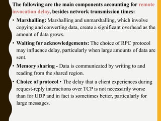
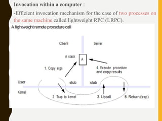
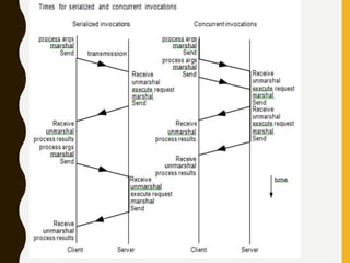
Download to read offline

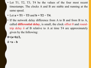

![Rules of Vector Time
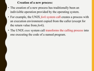
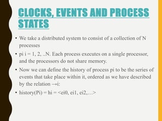
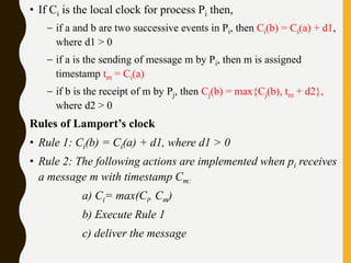
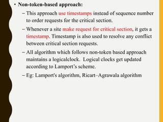
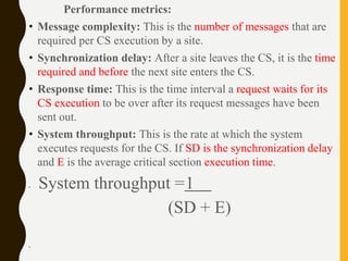
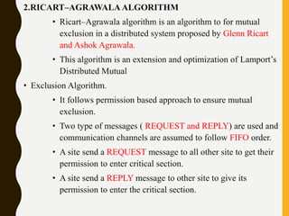
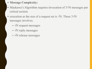
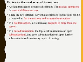
• Rule 1: Before executing an event, process pi updates its local
logical time as follows:
• uti[i] : =uti[i] + d (d >0)
• Rule 2: Each message m is piggybacked with the vector clock
vt of the sender process at sending time. On the receipt of such
a message (m,vt), process
• pi executes the following sequence of actions:
• update its global logical time
• 1 ≤k ≤n : uti[k] : =max (uti[k], ut[k])
• execute R1
• deliver the message m](https://image.slidesharecdn.com/unitiidis-230802171633-47d415e3/85/UNIT-II-DIS-pptx-45-320.jpg)
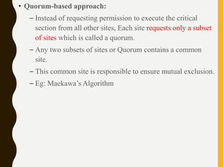
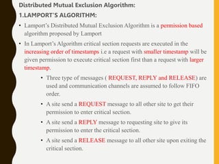
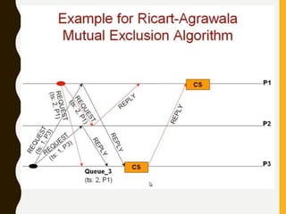
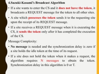
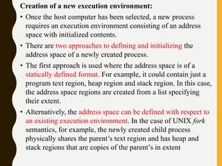
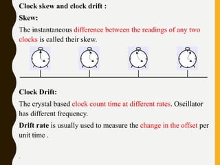
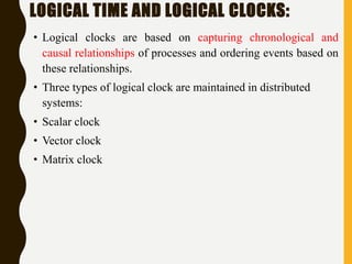
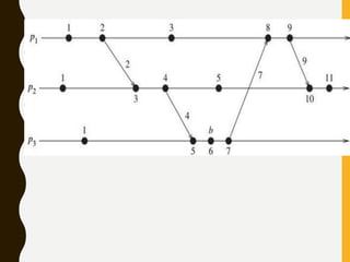
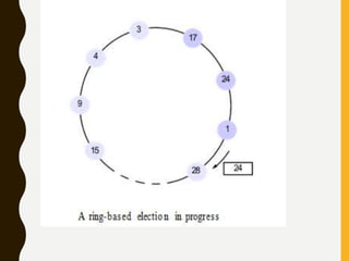
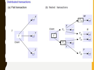
![1. A ring-based election algorithm
• The algorithm of Chang and Roberts [1979] is suitable for a
collection of processes arranged in a logical ring.
• Each process Pi has a communication channel to the next
process in the ring, P(i + 1)mod N , and all messages are sent
clockwise around the ring.
• We assume that no failures occur, and that the system is
asynchronous.
• The goal of this algorithm is to elect a single process called the
coordinator, which is the process with the largest identifier.
• Initially, every process is marked as a non-participant in an
election. Any process can begin an election. It proceeds by
marking itself as a participant, placing its identifier in an
election message and sending it to its clockwise neighbor.](https://image.slidesharecdn.com/unitiidis-230802171633-47d415e3/85/UNIT-II-DIS-pptx-66-320.jpg)
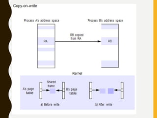
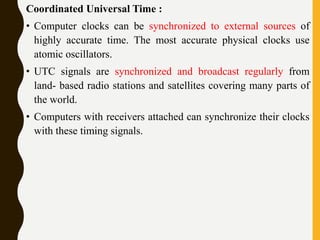
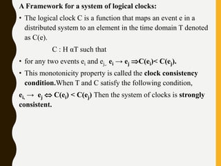
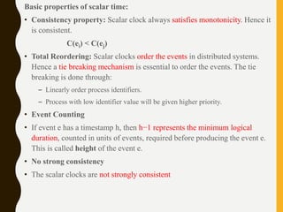
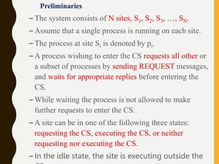
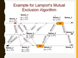
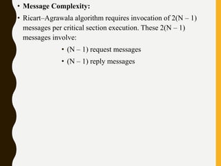
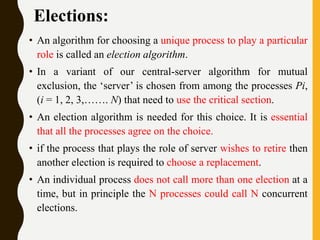
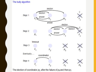
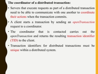
![2. The bully algorithm:
The bully algorithm [Garcia-Molina 1982] allows processes to
crash during an election, although it assumes that message
delivery between processes is reliable.
• The bully algorithm, on the other hand, assumes that each
process knows which processes have higher identifiers, and that
it can communicate with all such processes.
• There are three types of message in this algorithm:
• an election message is sent to announce an election;
• an answer message is sent in response to an election message
• a coordinator message is sent to announce the identity of the
elected process – the new coordinator’.](https://image.slidesharecdn.com/unitiidis-230802171633-47d415e3/85/UNIT-II-DIS-pptx-68-320.jpg)

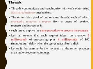
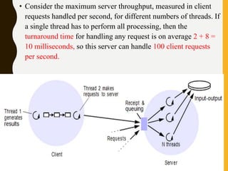
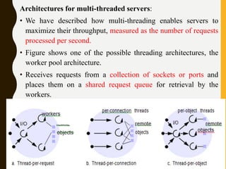
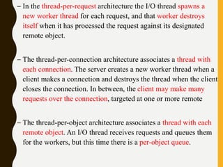
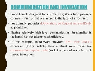
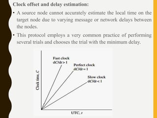
The document discusses processes, threads, communication, and synchronization in distributed systems. It covers key concepts like processes and threads, address spaces, creation of new processes, shared memory regions, thread communication and synchronization, remote invocation, and architectures for multi-threaded servers. Communication primitives provided by some distributed operating systems are also summarized.