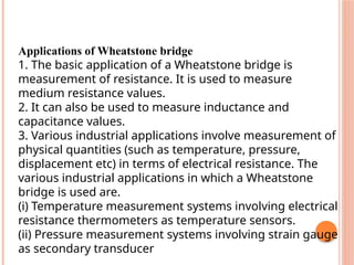
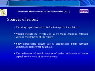
UNIT - 4
BRIDGES
UNIT IV
Bridge circuits- Wheat stone bridge, measurement of very
low resistance, Measurement of inductance- Maxwell’s
bridge, Anderson bridge. Measurement of capacitance-
Schearing Bridge.Wien Bridge, Errors and precautions in
using bridges.
Q-meter; principle of operation, measurement methods and
sources of errors.
Counters : principle of operation -modes of operation-
totalizing mode, frequency mode and time period mode-
sources of errors.
Applications of Wheatstone bridge
1. The basic application of a Wheatstone bridge is
measurement of resistance. It is used to measure
medium resistance values.
2. It can also be used to measure inductance and
capacitance values.
3. Various industrial applications involve measurement of
physical quantities (such as temperature, pressure,
displacement etc) in terms of electrical resistance. The
various industrial applications in which a Wheatstone
bridge is used are.
(i) Temperature measurement systems involving electrical
resistance thermometers as temperature sensors.
(ii) Pressure measurement systems involving strain gauge
as secondary transducer
(iii) Measurement of static and dynamic strains.
(iv) It is used with explosive meter to measure the
amount of combustible gases in a sample.
(v) Temperature measurement systems involving
electrical resistance thermometers as temperature
sensors.
(vi) Pressure measurement systems involving strain
gauge as secondary transducer.
4. Measurement of static and dynamic strains.
5. It is used with explosive meter to measure the
amount of combustible gases in a sample.
Limitations of Wheatstone bridge
1. Wheatstone bridge is not suitable for
measuring low resistances because the
resistance of leads and
contacts of the bridge cause errors in the value
measured by the Wheatstone bridge and thus
affects the
measurement of low resistances.
2. Wheatstone bridge cannot be used for
measurement of high resistance also, because a
galvanometer is not sensitive to the imbalance of
the bridge caused by the high resistance of the
bridge. This problem
can be overcome by replacing the galvanometer
with a Vacuum Type Volt Meter (VTVM) and by
replacing the battery with a power supply.
Electronic Measurements & Instrumentation (EMI)
KELVIN’S BRIDGE
• When the resistance to be measured is
of the order of magnitude of bridge
contact and lead resistance, a modified
form of Wheatstone’s bridge, the
Kelvin bridge is employed.
• Kelvin’s bridge is a modification of
Wheatstone’s bridge and is used to
measure values of resistance below 1
Ω.
• In low resistance measurement, the
resistance of the leads connecting the
unknown resistance to the terminal of
the bridge circuit may affect the
measurement.
Electronic Measurements & Instrumentation (EMI) Unit-4
KELVIN’S BRIDGE
• Consider
the
circuit in
Fig.,
where Ry represents the
resistance of the connecting
leads from R3 to Rx (unknown
resistance).
• The galvanometer can be
connected either to point c or to
point a.
• When it is connected to point a,
the resistance Ry, of the
connecting lead is added to the
unknown resistance Rx,
resulting in too high indication
for Rx.
Electronic Measurements & Instrumentation (EMI) Unit-4
KELVIN’S BRIDGE
• When the connection is made to
point c, Ry is added to the bridge
arm R3 and resulting
measurement of Rx is lower than
the actual value, because now the
actual value of R3 is higher than
its nominal value by the
resistance Ry.
• If the galvanometer is connected
to point b, in between points c
and a, in such a way that the ratio
of the resistance from c to b and
that from a to b equals the ratio of
resistances R1 and R2, then
Electronic Measurements & Instrumentation (EMI) Unit-4
AC BRIDGES
A.C.Bridges are those circuits which are
used to measured the unknown resistances,
capacitance, inductance, frequency and
mutual inductance.
ANDERSON BRIDGE
In the Anderson Bridge, the unknown
inductance is measured in terms of a known
capacitance and resistance.
This method is capable of precise
measurements of inductance over a wide
range of values from a few micro-henrys to
several henrys and is the best bridge
method.
Electronic Measurements & Instrumentation (EMI) Unit-4
Sources of errors:
• The stray capacitance effects due to imperfect insulation
• Mutual inductance effects due to magnetic coupling between
various components of the bridge.
• Stray capacitance effects due to electrostatic fields between
conductors at different potentials.
• The existence of small amount of series resistance or shunt
capacitance in case of pure resistance.
Electronic Measurements & Instrumentation (EMI) Unit-4
Methods of reducing bridge errors:
• Select the high-quality components
• Use proper bridge layout
• All the leads to a single corner should brought as near as
possible to the same point.
• A pair of leads to a component should not form a large loop
• Use insulating stands.
• If there is more than one inductor in a bridge circuit, leads may
have to be quite large
• Operate the bridge at sufficient sensitivity.
Electronic Measurements & Instrumentation (EMI) Unit-4
Methods of reducing bridge errors:
• Self inductance is important only when the coils are used, and
the source has high frequency
• Frequency and waveform errors are overcome by using wave
filters which eliminates the unwanted harmonics from the source
or by using vibration galvanometers which will respond only to
the frequency for which they are tuned.
Electronic Measurements & Instrumentation (EMI) Unit-4
Errors and Precautions in using Bridges
• Assuming that a suitable method of
measurement has been selected and that the
source and detector are given, there are
some precautions which must be observed
to obtain accurate readings.
• The leads should be carefully laid out in
such a way that no loops or long lengths
enclosing magnetic flux are produced, with
consequent stray inductance errors.
Electronic Measurements & Instrumentation (EMI)
Errors and Precautions in using Bridges
• With a large L, the self-capacitance of the leads is more
important than their inductance, so they should be
spaced relatively far apart.
• In measuring a capacitor, it is important to keep the
lead capacitance as low as possible. For this reason the
leads should not be too close together and should be
made of fine wire.
• In very precise inductive and capacitances
measurements, leads are encased in metal tubes to
shield them from mutual electromagnetic action and are
used or designed to completely shield the bridge.
Q-METER
 The Q-meter is an instrument designed to measure some of the
electrical properties of coils and capacitors .
 The operation of this instrument is based on the series resonant
circuit,i.e the voltage across the coil or the capacitor is equal to
the applied voltage times the Q of the circuit.
 If a fixed voltage is applied to the circuit, a voltmeter across
the capacitor can be calibrated to read Q directly.
Q-METER CON…
 At resonance ,the following conditions are valid:
 Xc=XL
 Ec=IXc =IXL
 E = IR
 Where E = applied voltage
 I= circuit current
 Ec = voltage across the capacitor
 Xc = capacitive reactance
 XL = inductive reactance
 R = coil resistance
Q-METER CON…
 By definition Q is

 Therefore if E is maintained at a constant and known
level, a voltmeter connected across the capacitor can
be calibrated directly in terms of the circuit Q.
E
E
R
X
R
X
Q C
C
L



PRACTICAL Q METER
 A practical Q meter circuit is shown.
 The wide range oscillator with a frequency range from
50kHz to 50MHz delivers current to shunt resistance
RSH.
PRACTICAL Q METER CON..
 The value of this shunt is very low, typically on the order of
0.02Ω.
 It represents a voltage source of magnitude E with a very small
internal resistance.
 The voltage E across the shunt, corresponding to E is measured
with a meter marked “Multiply Q By” .
 The voltage across the variable capacitor, corresponding to EC is
measured with a voltmeter whose scale is calibrated directly in Q
values.
PRACTICAL Q METER CON..
 To make a measurement, the unknown coil is connected to
the test terminal of the instrument, and the circuit is tuned
to resonance either by setting the oscillator to a given
frequency and varying the internal resonating capacitor or
by presetting the capacitor to a desired value and adjusting
the frequency of the oscillator.
 The Q reading on the output meter must be multiplied by
the index setting of the “Multiply Q By” meter to obtain
the actual Q value.

UNIT 4 BRIDGES instrumetations .pptx

  • 1.
  • 2.
    UNIT IV Bridge circuits-Wheat stone bridge, measurement of very low resistance, Measurement of inductance- Maxwell’s bridge, Anderson bridge. Measurement of capacitance- Schearing Bridge.Wien Bridge, Errors and precautions in using bridges. Q-meter; principle of operation, measurement methods and sources of errors. Counters : principle of operation -modes of operation- totalizing mode, frequency mode and time period mode- sources of errors.
  • 17.
    Applications of Wheatstonebridge 1. The basic application of a Wheatstone bridge is measurement of resistance. It is used to measure medium resistance values. 2. It can also be used to measure inductance and capacitance values. 3. Various industrial applications involve measurement of physical quantities (such as temperature, pressure, displacement etc) in terms of electrical resistance. The various industrial applications in which a Wheatstone bridge is used are. (i) Temperature measurement systems involving electrical resistance thermometers as temperature sensors. (ii) Pressure measurement systems involving strain gauge as secondary transducer
  • 18.
    (iii) Measurement ofstatic and dynamic strains. (iv) It is used with explosive meter to measure the amount of combustible gases in a sample. (v) Temperature measurement systems involving electrical resistance thermometers as temperature sensors. (vi) Pressure measurement systems involving strain gauge as secondary transducer. 4. Measurement of static and dynamic strains. 5. It is used with explosive meter to measure the amount of combustible gases in a sample.
  • 19.
    Limitations of Wheatstonebridge 1. Wheatstone bridge is not suitable for measuring low resistances because the resistance of leads and contacts of the bridge cause errors in the value measured by the Wheatstone bridge and thus affects the measurement of low resistances. 2. Wheatstone bridge cannot be used for measurement of high resistance also, because a galvanometer is not sensitive to the imbalance of the bridge caused by the high resistance of the bridge. This problem can be overcome by replacing the galvanometer with a Vacuum Type Volt Meter (VTVM) and by replacing the battery with a power supply.
  • 20.
    Electronic Measurements &Instrumentation (EMI) KELVIN’S BRIDGE • When the resistance to be measured is of the order of magnitude of bridge contact and lead resistance, a modified form of Wheatstone’s bridge, the Kelvin bridge is employed. • Kelvin’s bridge is a modification of Wheatstone’s bridge and is used to measure values of resistance below 1 Ω. • In low resistance measurement, the resistance of the leads connecting the unknown resistance to the terminal of the bridge circuit may affect the measurement.
  • 21.
    Electronic Measurements &Instrumentation (EMI) Unit-4 KELVIN’S BRIDGE • Consider the circuit in Fig., where Ry represents the resistance of the connecting leads from R3 to Rx (unknown resistance). • The galvanometer can be connected either to point c or to point a. • When it is connected to point a, the resistance Ry, of the connecting lead is added to the unknown resistance Rx, resulting in too high indication for Rx.
  • 22.
    Electronic Measurements &Instrumentation (EMI) Unit-4 KELVIN’S BRIDGE • When the connection is made to point c, Ry is added to the bridge arm R3 and resulting measurement of Rx is lower than the actual value, because now the actual value of R3 is higher than its nominal value by the resistance Ry. • If the galvanometer is connected to point b, in between points c and a, in such a way that the ratio of the resistance from c to b and that from a to b equals the ratio of resistances R1 and R2, then
  • 23.
    Electronic Measurements &Instrumentation (EMI) Unit-4
  • 24.
    Electronic Measurements &Instrumentation (EMI) Unit-4
  • 25.
    AC BRIDGES A.C.Bridges arethose circuits which are used to measured the unknown resistances, capacitance, inductance, frequency and mutual inductance.
  • 32.
    ANDERSON BRIDGE In theAnderson Bridge, the unknown inductance is measured in terms of a known capacitance and resistance. This method is capable of precise measurements of inductance over a wide range of values from a few micro-henrys to several henrys and is the best bridge method.
  • 37.
    Electronic Measurements &Instrumentation (EMI) Unit-4 Sources of errors: • The stray capacitance effects due to imperfect insulation • Mutual inductance effects due to magnetic coupling between various components of the bridge. • Stray capacitance effects due to electrostatic fields between conductors at different potentials. • The existence of small amount of series resistance or shunt capacitance in case of pure resistance.
  • 38.
    Electronic Measurements &Instrumentation (EMI) Unit-4 Methods of reducing bridge errors: • Select the high-quality components • Use proper bridge layout • All the leads to a single corner should brought as near as possible to the same point. • A pair of leads to a component should not form a large loop • Use insulating stands. • If there is more than one inductor in a bridge circuit, leads may have to be quite large • Operate the bridge at sufficient sensitivity.
  • 39.
    Electronic Measurements &Instrumentation (EMI) Unit-4 Methods of reducing bridge errors: • Self inductance is important only when the coils are used, and the source has high frequency • Frequency and waveform errors are overcome by using wave filters which eliminates the unwanted harmonics from the source or by using vibration galvanometers which will respond only to the frequency for which they are tuned.
  • 40.
    Electronic Measurements &Instrumentation (EMI) Unit-4 Errors and Precautions in using Bridges • Assuming that a suitable method of measurement has been selected and that the source and detector are given, there are some precautions which must be observed to obtain accurate readings. • The leads should be carefully laid out in such a way that no loops or long lengths enclosing magnetic flux are produced, with consequent stray inductance errors.
  • 41.
    Electronic Measurements &Instrumentation (EMI) Errors and Precautions in using Bridges • With a large L, the self-capacitance of the leads is more important than their inductance, so they should be spaced relatively far apart. • In measuring a capacitor, it is important to keep the lead capacitance as low as possible. For this reason the leads should not be too close together and should be made of fine wire. • In very precise inductive and capacitances measurements, leads are encased in metal tubes to shield them from mutual electromagnetic action and are used or designed to completely shield the bridge.
  • 42.
    Q-METER  The Q-meteris an instrument designed to measure some of the electrical properties of coils and capacitors .  The operation of this instrument is based on the series resonant circuit,i.e the voltage across the coil or the capacitor is equal to the applied voltage times the Q of the circuit.  If a fixed voltage is applied to the circuit, a voltmeter across the capacitor can be calibrated to read Q directly.
  • 43.
    Q-METER CON…  Atresonance ,the following conditions are valid:  Xc=XL  Ec=IXc =IXL  E = IR  Where E = applied voltage  I= circuit current  Ec = voltage across the capacitor  Xc = capacitive reactance  XL = inductive reactance  R = coil resistance
  • 44.
    Q-METER CON…  Bydefinition Q is   Therefore if E is maintained at a constant and known level, a voltmeter connected across the capacitor can be calibrated directly in terms of the circuit Q. E E R X R X Q C C L   
  • 45.
    PRACTICAL Q METER A practical Q meter circuit is shown.  The wide range oscillator with a frequency range from 50kHz to 50MHz delivers current to shunt resistance RSH.
  • 46.
    PRACTICAL Q METERCON..  The value of this shunt is very low, typically on the order of 0.02Ω.  It represents a voltage source of magnitude E with a very small internal resistance.  The voltage E across the shunt, corresponding to E is measured with a meter marked “Multiply Q By” .  The voltage across the variable capacitor, corresponding to EC is measured with a voltmeter whose scale is calibrated directly in Q values.
  • 47.
    PRACTICAL Q METERCON..  To make a measurement, the unknown coil is connected to the test terminal of the instrument, and the circuit is tuned to resonance either by setting the oscillator to a given frequency and varying the internal resonating capacitor or by presetting the capacitor to a desired value and adjusting the frequency of the oscillator.  The Q reading on the output meter must be multiplied by the index setting of the “Multiply Q By” meter to obtain the actual Q value.