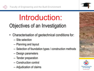
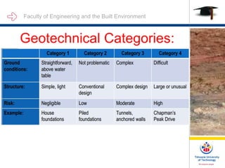
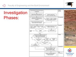
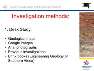
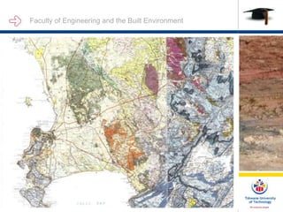
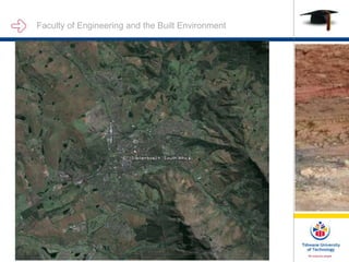
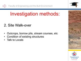
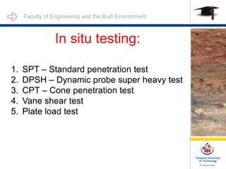
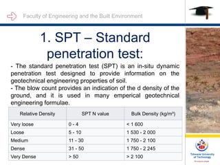
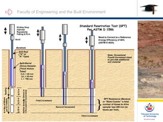
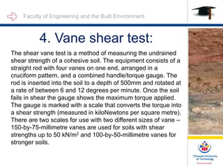
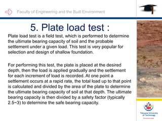
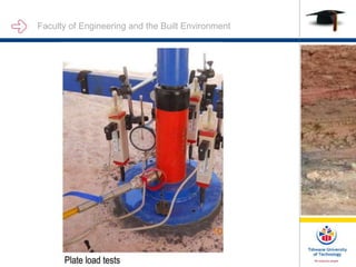
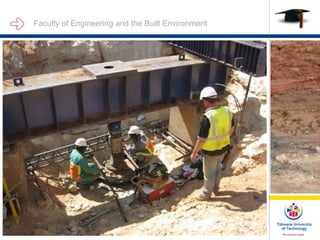
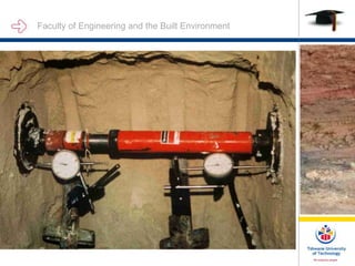
Unit 2: Site Investigation
By
SM RAKGATE
Faculty of Engineering and the Built Environment
Introduction:
Faculty of Engineering and the Built Environment
Geotechnical Categories:
Faculty of Engineering and the Built Environment
Investigation
Phases:
Faculty of Engineering and the Built Environment
Investigation methods:
1. Desk Study:
• Geological maps
• Google images
• Arial photographs
• Previous investigations
• Brink books (Engineering Geology of
Southern Africa)
Faculty of Engineering and the Built Environment
INTRODUCTION:
Faculty of Engineering and the Built Environment
INTRODUCTION:
This
Faculty of Engineering and the Built Environment
INTRODUCTION:
This
Faculty of Engineering and the Built Environment
INTRODUCTION:
This
Faculty of Engineering and the Built Environment
INTRODUCTION:
This
Faculty of Engineering and the Built Environment
Investigation methods:
2. Site Walk-over
• Outcrops, borrow pits, stream courses, etc
• Condition of existing structures
• Talk to Locals
Faculty of Engineering and the Built Environment
INTRODUCTION:
This
Faculty of Engineering and the Built Environment
INTRODUCTION:
This
Faculty of Engineering and the Built Environment
INTRODUCTION:
This
Faculty of Engineering and the Built Environment
Test Holes:
• Test Pits
• Augur holes
• Horeholes
Faculty of Engineering and the Built Environment
Safety in Trial Holes:
Factors influencing trail hole
stability
Faculty of Engineering and the Built Environment
INTRODUCTION:
This
Faculty of Engineering and the Built Environment
INTRODUCTION:
This
Faculty of Engineering and the Built Environment
INTRODUCTION:
This
Faculty of Engineering and the Built Environment
INTRODUCTION:
Faculty of Engineering and the Built Environment
Safety in Trail Holes:
Factors influencing trail hole stability
Faculty of Engineering and the Built Environment
Cohesion affected by many
things:
1. Water
Faculty of Engineering and the Built Environment
INTRODUCTION:
This
Faculty of Engineering and the Built Environment
Cohesion affected by many
things:
1. Water
2. Cohesionless material (sand and
gravels)
Faculty of Engineering and the Built Environment
INTRODUCTION:
This
Faculty of Engineering and the Built Environment
INTRODUCTION:
This
Faculty of Engineering and the Built Environment
Cohesion affected by many
things:
1. Water
2. Cohesionless material (sand and
gravels)
3. Fill
Faculty of Engineering and the Built Environment
INTRODUCTION:
This
Faculty of Engineering and the Built Environment
INTRODUCTION:
This
Faculty of Engineering and the Built Environment
Cohesion affected by many
things:
1. Water
2. Cohesionless material (sand and
gravels)
3. Fill
4. Tension cracks
Faculty of Engineering and the Built Environment
INTRODUCTION:
This
Faculty of Engineering and the Built Environment
INTRODUCTION:
This
Faculty of Engineering and the Built Environment
Cohesion affected by many
things:
1. Water
2. Cohesionless material (sand and
gravels)
3. Fill
4. Tension cracks
5. Loose material near surface
Faculty of Engineering and the Built Environment
INTRODUCTION:
This
Faculty of Engineering and the Built Environment
INTRODUCTION:
This
Faculty of Engineering and the Built Environment
Field and Laboratory tests:
This
Faculty of Engineering and the Built Environment
In situ testing:
1. SPT – Standard penetration test
2. DPSH – Dynamic probe super heavy test
3. CPT – Cone penetration test
4. Vane shear test
5. Plate load test
Faculty of Engineering and the Built Environment
1. SPT – Standard
penetration test:
- The standard penetration test (SPT) is an in-situ dynamic
penetration test designed to provide information on the
geotechnical engineering properties of soil.
- The blow count provides an indication of the d density of the
ground, and it is used in many emperical geotechnical
engineering formulae.
•
Relative Density SPT N value Bulk Density (kg/m³)
Very loose 0 - 4 < 1 600
Loose 5 - 10 1 530 - 2 000
Medium 11 - 30 1 750 - 2 100
Dense 31 - 50 1 750 - 2 245
Very Dense > 50 > 2 100
Faculty of Engineering and the Built Environment
INTRODUCTION:
This
Faculty of Engineering and the Built Environment
2. DPSH – Dynamic probe
super heavy test:
Like the SPT, the Dynamic Probing Super Heavy (DPSH)
uses a hammer that delivers energy to a rod string by
dropping a weight of 63.5kg from a height of 760mm. Unlike
the SPT, a solid cone is driven instead of a split spoon
sampler. Soil samples are not brought to the surface so a
continuous record of penetration is recorded without tripping
tool strings in and out of the borehole being evaluated. The
International Society for Soil Mechanics and Foundation
Engineering (ISSMFE) has outlined a procedure called
Dynamic Probing Super Heavy (DPSH) which is designed to
closely simulate the dimensions of the Standard Penetration
Test(SPT).
Faculty of Engineering and the Built Environment
INTRODUCTION:
This
Faculty of Engineering and the Built Environment
3. CPT – Cone penetration
test:
The cone penetration test (CPT) is a common in situ testing
method used to determine the geotechnical engineering
properties of soils and assessing subsurface stratigraphy. The
testing apparatus consists of an instrumented still cone having
a tip facing down, with an usual apex angle of 60° and cross-
section area of 1000 mm². The code is attached to a internal
still rode than can run inside a outer hollow rod, which itself is
attached to a sleeve. In the more elaborate CPT instruments,
the cone and the sleeve (attached to the outer rod) can move
separately.
Faculty of Engineering and the Built Environment
INTRODUCTION:
This
Faculty of Engineering and the Built Environment
4. Vane shear test:
The shear vane test is a method of measuring the undrained
shear strength of a cohesive soil. The equipment consists of a
straight rod with four vanes on one end, arranged in a
cruciform pattern, and a combined handle/torque gauge. The
rod is inserted into the soil to a depth of 500mm and rotated at
a rate of between 6 and 12 degrees per minute. Once the soil
fails in shear the gauge shows the maximum torque applied.
The gauge is marked with a scale that converts the torque into
a shear strength (measured in kiloNewtons per square metre).
There are two scales for use with two different sizes of vane –
150-by-75-millimetre vanes are used for soils with shear
strengths up to 50 kN/m2 and 100-by-50-millimetre vanes for
stronger soils.
Faculty of Engineering and the Built Environment
INTRODUCTION:
This
Faculty of Engineering and the Built Environment
INTRODUCTION:
Faculty of Engineering and the Built Environment
5. Plate load test :
Plate load test is a field test, which is performed to determine
the ultimate bearing capacity of soil and the probable
settlement under a given load. This test is very popular for
selection and design of shallow foundation.
For performing this test, the plate is placed at the desired
depth, then the load is applied gradually and the settlement
for each increment of load is recorded. At one point a
settlement occurs at a rapid rate, the total load up to that point
is calculated and divided by the area of the plate to determine
the ultimate bearing capacity of soil at that depth. The ultimate
bearing capacity is then divided by a safety factor (typically
2.5~3) to determine the safe bearing capacity.
Faculty of Engineering and the Built Environment

Unit 2 - Site Investigation.ppt

  • 1.
    Unit 2: SiteInvestigation By SM RAKGATE Faculty of Engineering and the Built Environment
  • 2.
    Faculty of Engineeringand the Built Environment Introduction:
  • 3.
    Faculty of Engineeringand the Built Environment Geotechnical Categories:
  • 4.
    Faculty of Engineeringand the Built Environment Investigation Phases:
  • 5.
    Faculty of Engineeringand the Built Environment Investigation methods: 1. Desk Study: • Geological maps • Google images • Arial photographs • Previous investigations • Brink books (Engineering Geology of Southern Africa)
  • 6.
    Faculty of Engineeringand the Built Environment INTRODUCTION:
  • 7.
    Faculty of Engineeringand the Built Environment INTRODUCTION: This
  • 8.
    Faculty of Engineeringand the Built Environment INTRODUCTION: This
  • 9.
    Faculty of Engineeringand the Built Environment INTRODUCTION: This
  • 10.
    Faculty of Engineeringand the Built Environment INTRODUCTION: This
  • 11.
    Faculty of Engineeringand the Built Environment Investigation methods: 2. Site Walk-over • Outcrops, borrow pits, stream courses, etc • Condition of existing structures • Talk to Locals
  • 12.
    Faculty of Engineeringand the Built Environment INTRODUCTION: This
  • 13.
    Faculty of Engineeringand the Built Environment INTRODUCTION: This
  • 14.
    Faculty of Engineeringand the Built Environment INTRODUCTION: This
  • 15.
    Faculty of Engineeringand the Built Environment Test Holes: • Test Pits • Augur holes • Horeholes
  • 16.
    Faculty of Engineeringand the Built Environment
  • 17.
    Faculty of Engineeringand the Built Environment
  • 18.
    Faculty of Engineeringand the Built Environment
  • 19.
    Faculty of Engineeringand the Built Environment
  • 20.
    Faculty of Engineeringand the Built Environment
  • 21.
    Faculty of Engineeringand the Built Environment
  • 22.
    Faculty of Engineeringand the Built Environment
  • 23.
    Faculty of Engineeringand the Built Environment
  • 24.
    Faculty of Engineeringand the Built Environment Safety in Trial Holes: Factors influencing trail hole stability
  • 25.
    Faculty of Engineeringand the Built Environment
  • 26.
    Faculty of Engineeringand the Built Environment INTRODUCTION: This
  • 27.
    Faculty of Engineeringand the Built Environment INTRODUCTION: This
  • 28.
    Faculty of Engineeringand the Built Environment INTRODUCTION: This
  • 29.
    Faculty of Engineeringand the Built Environment INTRODUCTION:
  • 30.
    Faculty of Engineeringand the Built Environment Safety in Trail Holes: Factors influencing trail hole stability
  • 31.
    Faculty of Engineeringand the Built Environment Cohesion affected by many things: 1. Water
  • 32.
    Faculty of Engineeringand the Built Environment INTRODUCTION: This
  • 33.
    Faculty of Engineeringand the Built Environment Cohesion affected by many things: 1. Water 2. Cohesionless material (sand and gravels)
  • 34.
    Faculty of Engineeringand the Built Environment INTRODUCTION: This
  • 35.
    Faculty of Engineeringand the Built Environment INTRODUCTION: This
  • 36.
    Faculty of Engineeringand the Built Environment Cohesion affected by many things: 1. Water 2. Cohesionless material (sand and gravels) 3. Fill
  • 37.
    Faculty of Engineeringand the Built Environment INTRODUCTION: This
  • 38.
    Faculty of Engineeringand the Built Environment INTRODUCTION: This
  • 39.
    Faculty of Engineeringand the Built Environment Cohesion affected by many things: 1. Water 2. Cohesionless material (sand and gravels) 3. Fill 4. Tension cracks
  • 40.
    Faculty of Engineeringand the Built Environment INTRODUCTION: This
  • 41.
    Faculty of Engineeringand the Built Environment INTRODUCTION: This
  • 42.
    Faculty of Engineeringand the Built Environment Cohesion affected by many things: 1. Water 2. Cohesionless material (sand and gravels) 3. Fill 4. Tension cracks 5. Loose material near surface
  • 43.
    Faculty of Engineeringand the Built Environment INTRODUCTION: This
  • 44.
    Faculty of Engineeringand the Built Environment INTRODUCTION: This
  • 45.
    Faculty of Engineeringand the Built Environment Field and Laboratory tests: This
  • 46.
    Faculty of Engineeringand the Built Environment In situ testing: 1. SPT – Standard penetration test 2. DPSH – Dynamic probe super heavy test 3. CPT – Cone penetration test 4. Vane shear test 5. Plate load test
  • 47.
    Faculty of Engineeringand the Built Environment 1. SPT – Standard penetration test: - The standard penetration test (SPT) is an in-situ dynamic penetration test designed to provide information on the geotechnical engineering properties of soil. - The blow count provides an indication of the d density of the ground, and it is used in many emperical geotechnical engineering formulae. • Relative Density SPT N value Bulk Density (kg/m³) Very loose 0 - 4 < 1 600 Loose 5 - 10 1 530 - 2 000 Medium 11 - 30 1 750 - 2 100 Dense 31 - 50 1 750 - 2 245 Very Dense > 50 > 2 100
  • 48.
    Faculty of Engineeringand the Built Environment INTRODUCTION: This
  • 49.
    Faculty of Engineeringand the Built Environment 2. DPSH – Dynamic probe super heavy test: Like the SPT, the Dynamic Probing Super Heavy (DPSH) uses a hammer that delivers energy to a rod string by dropping a weight of 63.5kg from a height of 760mm. Unlike the SPT, a solid cone is driven instead of a split spoon sampler. Soil samples are not brought to the surface so a continuous record of penetration is recorded without tripping tool strings in and out of the borehole being evaluated. The International Society for Soil Mechanics and Foundation Engineering (ISSMFE) has outlined a procedure called Dynamic Probing Super Heavy (DPSH) which is designed to closely simulate the dimensions of the Standard Penetration Test(SPT).
  • 50.
    Faculty of Engineeringand the Built Environment INTRODUCTION: This
  • 51.
    Faculty of Engineeringand the Built Environment 3. CPT – Cone penetration test: The cone penetration test (CPT) is a common in situ testing method used to determine the geotechnical engineering properties of soils and assessing subsurface stratigraphy. The testing apparatus consists of an instrumented still cone having a tip facing down, with an usual apex angle of 60° and cross- section area of 1000 mm². The code is attached to a internal still rode than can run inside a outer hollow rod, which itself is attached to a sleeve. In the more elaborate CPT instruments, the cone and the sleeve (attached to the outer rod) can move separately.
  • 52.
    Faculty of Engineeringand the Built Environment INTRODUCTION: This
  • 53.
    Faculty of Engineeringand the Built Environment 4. Vane shear test: The shear vane test is a method of measuring the undrained shear strength of a cohesive soil. The equipment consists of a straight rod with four vanes on one end, arranged in a cruciform pattern, and a combined handle/torque gauge. The rod is inserted into the soil to a depth of 500mm and rotated at a rate of between 6 and 12 degrees per minute. Once the soil fails in shear the gauge shows the maximum torque applied. The gauge is marked with a scale that converts the torque into a shear strength (measured in kiloNewtons per square metre). There are two scales for use with two different sizes of vane – 150-by-75-millimetre vanes are used for soils with shear strengths up to 50 kN/m2 and 100-by-50-millimetre vanes for stronger soils.
  • 54.
    Faculty of Engineeringand the Built Environment INTRODUCTION: This
  • 55.
    Faculty of Engineeringand the Built Environment INTRODUCTION:
  • 56.
    Faculty of Engineeringand the Built Environment 5. Plate load test : Plate load test is a field test, which is performed to determine the ultimate bearing capacity of soil and the probable settlement under a given load. This test is very popular for selection and design of shallow foundation. For performing this test, the plate is placed at the desired depth, then the load is applied gradually and the settlement for each increment of load is recorded. At one point a settlement occurs at a rapid rate, the total load up to that point is calculated and divided by the area of the plate to determine the ultimate bearing capacity of soil at that depth. The ultimate bearing capacity is then divided by a safety factor (typically 2.5~3) to determine the safe bearing capacity.
  • 57.
    Faculty of Engineeringand the Built Environment
  • 58.
    Faculty of Engineeringand the Built Environment
  • 59.
    Faculty of Engineeringand the Built Environment
  • 60.
    Faculty of Engineeringand the Built Environment