Unit 1
Introduction tocomputer network
T1 - Overview of computer network
IT45103
NETWORKING
2.
Definition of Computer
Network
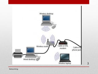
•A computer network is an interconnection of
computers and computing equipment using either
wires or radio waves and can share data and
computing resources.
• Computer networks that use radio waves are termed
wireless and can involve broadcast radio, microwaves
or satellite transmissions.
Networking
2
Types of computer
networks
•Networks spanning an area of several meters around
an individual are called personal area networks
(PANs). Most common is Bluetooth for headphones etc
• Networks a little larger in geographic size such as
spanning a room, a floor within a building, a building
or a campus are called Local Area Networks (LANs).
Networking
4
5.
Types of computer
networks(cont..)
• Networks that serve an area up to roughly 50
kilometers approximately the area of a typical city are
called metropolitan area networks (MANs).
• high-speed networks that interconnect businesses with
other businesses and the Internet.
• Usually is a business service offered by telcos/ISPs
• Large networks encompassing parts of states, multiple
states, countries and the world are wide area
networks (WANs). e.g. Internet
Networking
5
Advantages of
computer network
•Sharing of peripheral devices: Laser printer, disk
drives and scanner are examples of peripheral devices
– that is, hardware that is connected to a computer.
• Sharing of program and data: In most organizations,
people use the same software and need access to the
same information.
• Better communications: One of the greatest features of
networks is electronic mail. Also instant messaging
and calling apps such as WhatsApp are becoming
critical.
Networking
7
8.
Advantages of
computer network
(cont..)
•Security of information: data would be backed up or
duplicated on a networked storage device secured by
password.
• Access to databases: enable users to tap into
numerous databases, whether the private databases of
a company or the public databases of online services.
Networking
8
9.
The big pictureof
networks
• The most important in LANs include the following
hardware:
• Workstations, which are personal
computers/microcomputers (desktops, laptops, net
books, hand helds, etc) where users reside.
• Servers which are the computers that store network
software and shared public or private user files.
• Switches, which are the collection points for the wires
that interconnect the workstations.
• Routers, which are the connecting devices between local
area networks and wide area networks.
Networking
9
10.
The big pictureof
networks
• Wide area networks include the following
components:
• Nodes, which are the computing devices that allow
workstations to connect to the network and make
decisions about where to route a data.
• Some type of high-speed transmission line, which runs
from one node to another.
• A subnetwork or cloud which contains the nodes and
transmission lines, considered as a cohesive unit.
Networking
10
11.
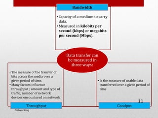
• Capacity ofa medium to carry
data.
•Measured in kilobits per
second (kbps) or megabits
per second (Mbps).
Bandwidth
• The measure of the transfer of
bits across the media over a
given period of time.
• Many factors influence
throughput ; amount and type of
traffic, number of network
devices encountered on network
Throughput
• Is the measure of usable data
transferred over a given period of
time
Goodput
Data transfer can
be measured in
three ways:
Networking
11
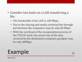
Example
• Consider twohosts on a LAN transferring a
file.
• The bandwidth of the LAN is 100 Mbps.
• Due to the sharing and media overhead the through
put between the computers may be only 60 Mbps.
• With the overhead of the encapsulation process of
the TCP/IP stack, the actual rate of the data
received by the destination computer, goodput, may
be only 40Mbps.
Networking
13
Networking
Network Models
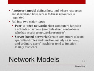
• Anetwork model defines how and where resources
are shared and how access to these resources is
regulated
• Fall into two major types
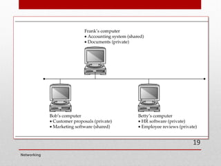
• Peer-to-peer network: Most computers function
as clients or servers (no centralized control over
who has access to network resources)
• Server-based network: Certain computers take on
specialized roles and function mainly as servers,
and ordinary users’ machines tend to function
mainly as clients
16
17.
Networking
Peer-to-Peer/Workgroup
Model
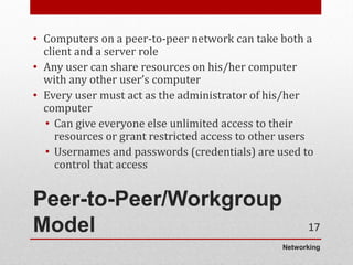
• Computers ona peer-to-peer network can take both a
client and a server role
• Any user can share resources on his/her computer
with any other user’s computer
• Every user must act as the administrator of his/her
computer
• Can give everyone else unlimited access to their
resources or grant restricted access to other users
• Usernames and passwords (credentials) are used to
control that access
17
18.
Networking
Peer-to-Peer/Workgroup
Model
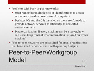
• Problems withPeer-to-peer networks:
• Must remember multiple sets of identifications to access
resources spread out over several computers
• Desktop PCs and the OSs installed on them aren’t made to
provide network services as efficiently as dedicated
network servers
• Data organization: If every machine can be a server, how
can users keep track of what information is stored on which
machine?
• Peer-to-peer networks are best suited for small organizations
that have small networks and small operating budgets
18
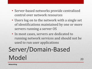
Server/Domain-Based
Model
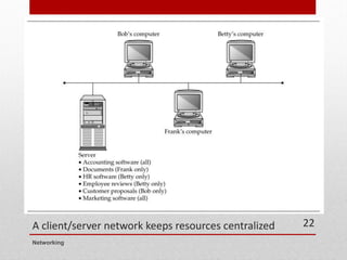
• Server-based networksprovide centralized
control over network resources
• Users log on to the network with a single set
of identifications maintained by one or more
servers running a server OS
• In most cases, servers are dedicated to
running network services and should not be
used to run user applications
Networking
20
21.
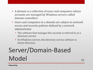
Server/Domain-Based
Model
• A domainis a collection of users and computers whose
accounts are managed by Windows servers called
domain controllers
• Users and computers in a domain are subject to network
access and security policies defined by a network
administrator
• The software that manages this security is referred to as a
directory service
• On Windows servers, the directory service software is
Active Directory
Networking
21
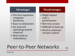
Peer-to-Peer Networks
Networking
23
Advantages
• Useless expensive
computer
hardware.
• Easy to administer.
• No network
operating system
required.
• More built-in
redundancy.
Disadvantages
• Might impact
user’s
performance
• Not very secure
• Difficult to back up
• Hard to maintain
version control
24.
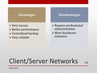
Client/Server Networks
Advantages
• Verysecure
• Better performance
• Centralized backup
• Very reliable
Disadvantages
• Require professional
administration
• More hardware-
intensive
Networking
24
25.
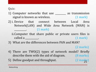
Quiz:
1) Computer networksthat use _________ as transmission
signal is known as wireless. (1 mark)
2) i. Device that connect between Local Area
Network(LAN) and Wide Area Network (WAN) is
__________. (1 mark)
ii.Computer that share public or private users files is
called a ___________. (1 mark)
3) What are the differences between PAN and MAN?
(2 marks)
4) There are TWO(2) types of network model? Briefly
describe them with the aid of diagram. (8 marks)
5) Define goodput and throughput. (2 marks)
Networking
25
• Topology basicallymeans shape.
• Network topology refers how a network is physically
laid out and how signals travel from one device to
another.
• Broken down into TWO topologies.
• The arrangement of cabling and how cables connect one
device to another in a network is considered the
network’s physical topology.
• The path data travel between computers on a network is
considered the network’s logical topology.
Networking
2
28.
Bus Topology
• Thefirst topology used in local area networking was
the bus topology
• A bus topology, more completely called a common bus
multipoint topology, is a network where, basically, a
single network cable is used from one end of the
network to the other, with different network devices
(called nodes) connected to the cable at different
locations.
• This topology is seldom used in modern networks
Networking
3
29.
Bus Topology
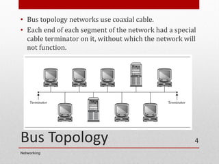
• Bustopology networks use coaxial cable.
• Each end of each segment of the network had a special
cable terminator on it, without which the network will
not function.
Networking
4
30.
Bus Topology
• Froma device's viewpoint, all other systems
communicate through the same, shared path.
• Because it is a shared media technology, mechanisms
must be put into place to determine network traffic
over the cable.
• Typically, collision detection (CD) or collision
avoidance (CA) algorithms are used in bus topologies
to determine network access along with concepts such
as "broadcasts" to reach every device on the cable.
• The biggest issue was that any cable break or issue
put the whole network offline
Networking
5
31.
Star Topology
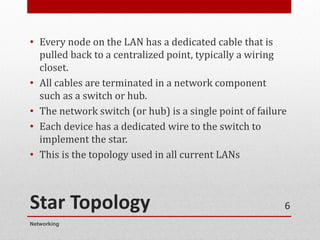
• Everynode on the LAN has a dedicated cable that is
pulled back to a centralized point, typically a wiring
closet.
• All cables are terminated in a network component
such as a switch or hub.
• The network switch (or hub) is a single point of failure
• Each device has a dedicated wire to the switch to
implement the star.
• This is the topology used in all current LANs
Networking
6
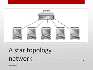
Star Topology
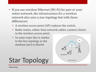
• Ifyou use wireless Ethernet (Wi-Fi) for part or your
entire network, the infrastructure for a wireless
network also uses a star topology but with these
differences:
• A wireless access point (AP) replaces the switch.
• Radio waves, rather than network cables, connect clients
to the wireless access point.
• In some ways this is similar
to the bus topology as the
medium (air) is shared
Networking
8
34.
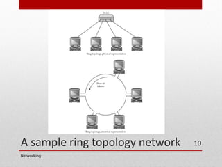
Ring Topology
• Aring topology may actually be a physical
arrangement of a network cable
• The network behaves like a ring, where the
network signals travel around the ring to each
node in turn.
• Ring topology LANs are based on Token Ring
• Like bus topology, ring topology is seldom
used in modern networks
Networking
9
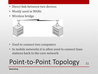
Point-to-Point Topology
• Directlink between two devices
• Mostly used in WANs
• Wireless bridge
• Used to connect two computers
• In mobile networks it is often used to connect base
stations back to the core network
Networking
11
37.
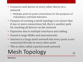
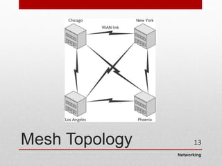
Mesh Topology
• Connectseach device to every other device in a
network
• Multiple point-to-point connections for the purposes of
redundancy and fault tolerance
• Purpose of creating a mesh topology is to ensure that
if one or more connections fail, there’s another path
for reaching all devices on the network
• Expensive due to multiple interfaces and cabling
• Found in large WANs and internetworks
• Internet is a large mesh network but every point is not
connected directly to every other point
• This is often called a partial mesh network
Networking
12
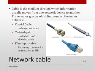
Network cable
• Cableis the medium through which information
usually moves from one network device to another.
Three major groups of cabling connect the major
networks:
• Coaxial Cable
• no longer common
• Twisted-pair
• unshielded and
shielded cable
• Fiber-optic cable
• Becoming common for
connections to ISP
Networking
15
41.
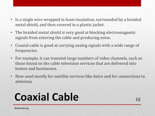
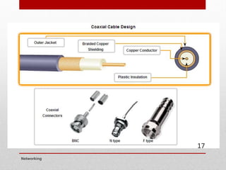
Coaxial Cable
• Isa single wire wrapped in foam insulation, surrounded by a braided
metal shield, and then covered in a plastic jacket.
• The braided metal shield is very good at blocking electromagnetic
signals from entering the cable and producing noise.
• Coaxial cable is good at carrying analog signals with a wide range of
frequencies.
• For example, it can transmit large numbers of video channels, such as
those found on the cable television services that are delivered into
homes and businesses.
• Now used mostly for satellite services like Astro and for connections to
antennas
Networking
16
Coaxial Cable (cont..)
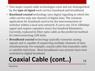
•Two major coaxial cable technologies exist and are distinguished
by the type of signal each carries; baseband and broadband.
• Baseband coaxial technology uses digital signaling in which the
cable carries only one channel of digital data. The common
application for baseband used to be the interconnection of
switches within a local area network. It carry one 10 to 100mbps
signal and require repeaters every few hundred kilometers.
Currently, replaced by fiber optic cable as the preferred method
for interconnecting LAN hubs.
• Broadband coaxial technology typically transmits analog
signals and is capable of supporting multiple channels of data
simultaneously. For example; coaxial cable that transmits cable
or satellite television. Most broadband coax systems have now
switched to digital baseband
Networking
18
44.
Coaxial Cable (cont..)
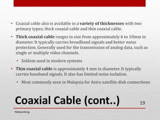
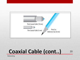
•Coaxial cable also is available in a variety of thicknesses with two
primary types; thick coaxial cable and thin coaxial cable.
• Thick coaxial cable ranges in size from approximately 6 to 10mm in
diameter. It typically carries broadband signals and better noise
protection. Generally used for the transmission of analog data, such as
single or multiple video channels.
• Seldom used in modern systems
• Thin coaxial cable is approximately 4 mm in diameter. It typically
carries baseband signals. It also has limited noise isolation.
• Most commonly seen in Malaysia for Astro satellite dish connections
Networking
19
Twisted-pair (unshielded
and shielded)cable
• Currently the most commonly used data
transmission medium.
• Used for most LANs and telephone
connections
• Consists of pairs of copper wires twisted
together to create magnetic field and thus
reduce interference.
• Two types of twisted pair are Shielded Twisted
Pair (STP) and Unshielded Twisted Pair (UTP).
Networking
21
47.
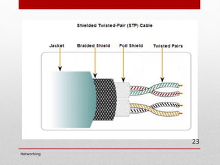
Shielded Twisted-Pair (STP)
Cable
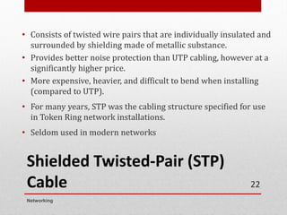
•Consists of twisted wire pairs that are individually insulated and
surrounded by shielding made of metallic substance.
• Provides better noise protection than UTP cabling, however at a
significantly higher price.
• More expensive, heavier, and difficult to bend when installing
(compared to UTP).
• For many years, STP was the cabling structure specified for use
in Token Ring network installations.
• Seldom used in modern networks
Networking
22
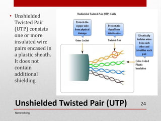
Unshielded Twisted Pair(UTP)
• Unshielded
Twisted Pair
(UTP) consists
one or more
insulated wire
pairs encased in
a plastic sheath.
It does not
contain
additional
shielding.
Networking
24
50.
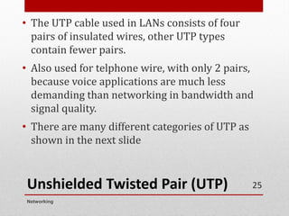
Unshielded Twisted Pair(UTP)
• The UTP cable used in LANs consists of four
pairs of insulated wires, other UTP types
contain fewer pairs.
• Also used for telphone wire, with only 2 pairs,
because voice applications are much less
demanding than networking in bandwidth and
signal quality.
• There are many different categories of UTP as
shown in the next slide
Networking
25
51.
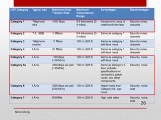
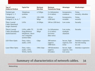
UTP Category Typicaluse Maximum Data
Transfer Rate
Maximum
Transmission
Range
Advantages Disadvantages
Category 1 Telephone
wire
<100 kbps 5-6 kilometers (3-
4 miles)
Inexpensive, easy to
install and interface
Security noise,
obsolete
Category 2 T-1, ISDN < 2Mbps 5-6 kilometers (3-
4 miles)
Same as category 1 Security noise,
obsolete
Category 3 Telephone
circuits
10 Mbps 100 m (328 ft) Same as category 1,
with less noise
Security noise,
obsolete
Category 4 LANs 20 Mbps 100 m (328 ft) Same as category 1,
with less noise
Security noise,
obsolete
Category 5 LANs 100 Mbps
(100 MHz)
100 m (328 ft) Same as category 1,
with less noise
Security, noise
Category 5e LANs 250 Mbps per pair
(125MHz)
100 m (328 ft) Same as Category 5.
Also includes
specifications for
connectors, patch
cords, and other
components.
Security, noise
Category 6 LANs 250 Mbps per pair
(250 MHz)
100 m (328 ft) Higher rates than
Category 5e, less
noise
Security, noise,
cost
Category 7 LANs 600MHz 100 m (328 ft) High data rates Security, noise,
cost
Networking
26
52.
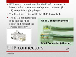
UTP connectors
• UTPuses a connection called the RJ-45 connector. It
looks similar to a common telephone connector (RJ-
11) except it is slightly larger.
• The RJ-45 has 8 pins while the RJ-11 has only 4.
• The RJ-11 connector can
plug into the RJ-45
socket and connect the
4 wires correctly
Networking
27
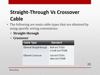
Straight-Through Vs Crossover
Cable
•The following are main cable types that are obtained by
using specific wiring conventions:
• Straight-through
• Crossover
Networking
29
55.
Use straight-throughcables for the following
connections:
• Switch to a router Ethernet port
• Computer to switch
Crossover cables directly connect the following
devices on a LAN:
• Switch to switch
• Router to router Ethernet port connection
• Computer to computer
• Computer to a router Ethernet port
Modern equipment can usually use either type of
cable
• The electronics automatically detects transmitter and receiver using
a technology called Auto-MDIX
Networking
30
56.
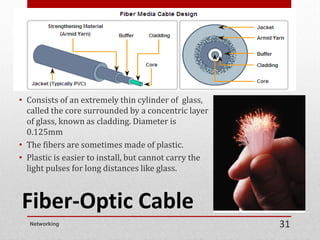
Fiber-Optic Cable
• Consistsof an extremely thin cylinder of glass,
called the core surrounded by a concentric layer
of glass, known as cladding. Diameter is
0.125mm
• The fibers are sometimes made of plastic.
• Plastic is easier to install, but cannot carry the
light pulses for long distances like glass.
Networking 31
57.
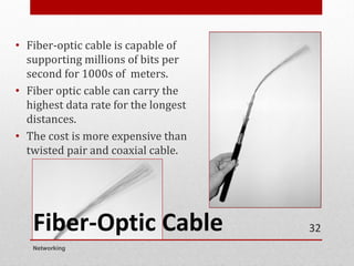
Fiber-Optic Cable
• Fiber-opticcable is capable of
supporting millions of bits per
second for 1000s of meters.
• Fiber optic cable can carry the
highest data rate for the longest
distances.
• The cost is more expensive than
twisted pair and coaxial cable.
Networking
32
Quiz:
1) Compare ShieldedTwisted-Pair (STP) and Unshielded Twisted-Pair
(UTP) cable. (6 marks)
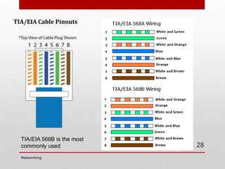
2) List the color of cable pinouts for T568A and T568B. (8 marks)
3) Define cladding for Fiber-Optic cable. (1 mark)
Networking
35
Wireless Media
• Radio,satellite transmissions, and infrared light are all
different forms of electromagnetic waves that are used to
transmit data
• In wireless transmissions, space is the medium
• Note in the following figure how each source occupies a
different set of frequencies
Networking
2
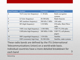
63.
These radio bandsare defined by the ITU (International
Telecommunications Union) on a world-wide basis.
Individual countries have a more detailed breakdown for
each band
Band Number Symbol Frequency Common Use
4 VLF (very low frequency) 3- 30 kHz Radio navigation
systems
5 LF (low frequency) 30-300 kHz Radio beacons
6 MF (medium frequency) 300 kHz-3 MHz AM radio
7 HF (high frequency) 3-30 MHz CB radio, Short Wave
radio
8 VHF (very high frequency) 3-300 MHz VHF TV, FM radio
9 UHF(ultra high frequency) 300 MHz-3 GHz UHF TV, cell phones,
pagers
10 SHF (superhigh frequency) 3-30 GHz Satellite
11 EHF (extremely high freq) 30-300 GHz Satellite, radar systems
Networking
3
64.
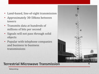
Terrestrial Microwave Transmission
•Land-based, line-of-sight transmission
• Approximately 30-50kms between
towers
• Transmits data at hundreds of
millions of bits per second
• Signals will not pass through solid
objects
• Popular with telephone companies
and business to business
transmissions
Networking
4
65.
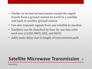
Satellite Microwave Transmission
•Similar to terrestrial microwave except the signal
travels from a ground station on earth to a satellite
and back to another ground station
• Can also transmit signals from one satellite to another
• Satellites can be classified by how far out into orbit
each one is (LEO, MEO, GEO, and HEO)
• Adds some delay due to length of transmission path
Networking
5
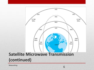
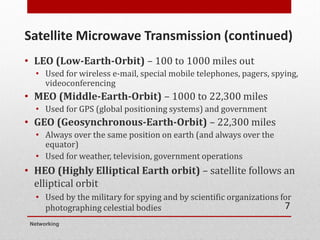
Satellite Microwave Transmission(continued)
• LEO (Low-Earth-Orbit) – 100 to 1000 miles out
• Used for wireless e-mail, special mobile telephones, pagers, spying,
videoconferencing
• MEO (Middle-Earth-Orbit) – 1000 to 22,300 miles
• Used for GPS (global positioning systems) and government
• GEO (Geosynchronous-Earth-Orbit) – 22,300 miles
• Always over the same position on earth (and always over the
equator)
• Used for weather, television, government operations
• HEO (Highly Elliptical Earth orbit) – satellite follows an
elliptical orbit
• Used by the military for spying and by scientific organizations for
photographing celestial bodies
Networking
7
68.
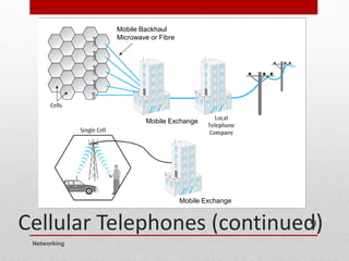
Cellular Telephones
• Wirelesstelephone service, also called mobile telephone,
cell phone, and Personal Communications Services (PCS)
• To support multiple users in a metropolitan area is broken
into cells (honeycomb-like pattern)
• Each cell has its own transmission tower and set of
assignable channels
Networking
8
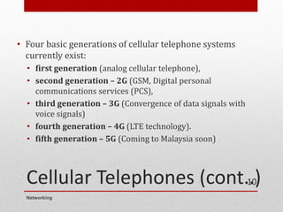
Cellular Telephones (cont..)
•Four basic generations of cellular telephone systems
currently exist:
• first generation (analog cellular telephone),
• second generation – 2G (GSM, Digital personal
communications services (PCS),
• third generation – 3G (Convergence of data signals with
voice signals)
• fourth generation – 4G (LTE technology).
• fifth generation – 5G (Coming to Malaysia soon)
Networking
10
71.
Infrared Transmissions
• Transmissionsthat use a focused ray of light in the infrared
frequency range
• Very common with remote control devices, but was also
used for device-to-device transfers, such as mobile phone to
computer
Networking
11
72.
WiMax - BroadbandWireless
Systems
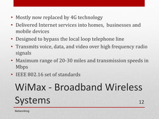
• Mostly now replaced by 4G technology
• Delivered Internet services into homes, businesses and
mobile devices
• Designed to bypass the local loop telephone line
• Transmits voice, data, and video over high frequency radio
signals
• Maximum range of 20-30 miles and transmission speeds in
Mbps
• IEEE 802.16 set of standards
Networking
12
73.
Bluetooth
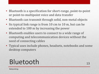
• Bluetooth isa specification for short-range, point-to-point
or point-to-multipoint voice and data transfer
• Bluetooth can transmit through solid, non-metal objects
• Its typical link range is from 10 cm to 10 m, but can be
extended to 100 m by increasing the power
• Bluetooth enables users to connect to a wide range of
computing and telecommunication devices without the
need of connecting cables
• Typical uses include phones, headsets, notebooks and some
desktop computers
Networking
13
74.
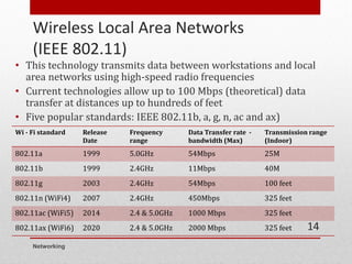
Wireless Local AreaNetworks
(IEEE 802.11)
• This technology transmits data between workstations and local
area networks using high-speed radio frequencies
• Current technologies allow up to 100 Mbps (theoretical) data
transfer at distances up to hundreds of feet
• Five popular standards: IEEE 802.11b, a, g, n, ac and ax)
Wi - Fi standard Release
Date
Frequency
range
Data Transfer rate -
bandwidth (Max)
Transmission range
(Indoor)
802.11a 1999 5.0GHz 54Mbps 25M
802.11b 1999 2.4GHz 11Mbps 40M
802.11g 2003 2.4GHz 54Mbps 100 feet
802.11n (WiFi4) 2007 2.4GHz 450Mbps 325 feet
802.11ac (WiFi5) 2014 2.4 & 5.0GHz 1000 Mbps 325 feet
802.11ax (WiFi6) 2020 2.4 & 5.0GHz 2000 Mbps 325 feet
Networking
14
An Overview
• Networkdevices are responsible for moving data from
one network cable to another.
• A good network design uses the correct device for
each of the various jobs the network must fulfill.
Networking
16
77.
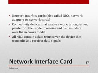
Network Interface Card
•Network interface cards (also called NICs, network
adapters or network cards)
• Connectivity devices that enable a workstation, server,
printer or other node to receive and transmit data
over the network media.
• All NICs contain a data transceiver, the device that
transmits and receives data signals.
Networking
17
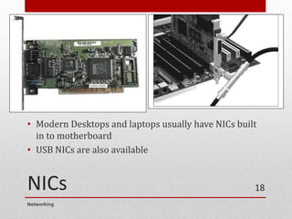
78.
NICs
• Modern Desktopsand laptops usually have NICs built
in to motherboard
• USB NICs are also available
Networking
18
79.
Repeater
• Device thatextends the distance of a particular
network run.
• It takes a weak network signal in on one side, boosts
the signal, and then sends it out its other side.
• A good example of the use of repeaters would be in a
local area network using a star topology with
unshielded twisted-pair cabling.
• Not commonly used in modern network practice
Networking
19
Hub
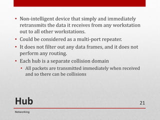
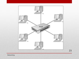
• Non-intelligent devicethat simply and immediately
retransmits the data it receives from any workstation
out to all other workstations.
• Could be considered as a multi-port repeater.
• It does not filter out any data frames, and it does not
perform any routing.
• Each hub is a separate collision domain
• All packets are transmitted immediately when received
and so there can be collisions
Networking
21
82.
Hub (cont..)
• Totalnetwork bandwidth is limited to the speed of the
hub.
• A 10Base-T hub provides 10Mb bandwidth maximum,
no matter how many ports it has.
• Supports half duplex only
• The devices can both transmit and receive on the media
but cannot do so simultaneously.
• Seldom used in modern networks
Networking
22
Switches
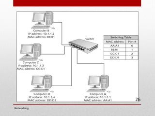
• Switches, canbe considered as intelligent hubs.
• Can be used to interconnect multiple workstations on
a single LAN or to interconnect multiple LANs.
• The primary function to direct the data frame to only
the addressed receiver.
• Thus, the switch needs to know where all the devices
are so that it can send the data out on the appropriate
link.
• It learns this by watching incoming traffic
Networking
24
85.
Switches (cont..)
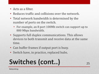
• Actsas a filter.
• Reduces traffic and collisions over the network.
• Total network bandwidth is determined by the
number of ports on the switch.
• For example, an 8 port 100Mb switch can support up to
800 Mbps bandwidth.
• Supports full duplex communications. This allows
devices to both transmit and receive data at the same
time.
• Can buffer frames if output port is busy.
• Switch have, in practice, replaced hubs.
Networking
25
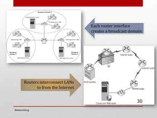
Router
• Connects localarea networks to wide area network and
between transmission links within a wide area network.
• Performs security functions and must be properly
programmed to accept or reject certain types of incoming
and outgoing data packets.
• Also determines the shortest route to a destination and use
it.
• Has the ability to break up broadcast domains and collision
domains.
Networking
27
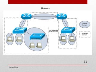
88.
Differences between routerand
switch
• Routers connect LANs; switches connect
computers
• Routers work with logical (IP) addresses; switches
work with physical (MAC) addresses
• Routers work with packets; switches with frames
• Routers don’t forward broadcasts; switches do
• Routers use routing tables; switches use switching
tables
Networking
28
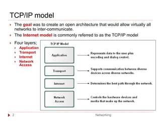
TCP/IP model
Thegoal was to create an open architecture that would allow virtually all
networks to inter-communicate.
The Internet model is commonly referred to as the TCP/IP model
Four layers;
Application
Transport
Internet
Network
Access
Networking
2
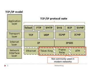
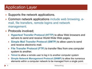
Application Layer
Supportsthe network applications.
Common network applications include web browsing, e-
mail, file transfers, remote logins and network
management.
Protocols involved;
Hypertext Transfer Protocol (HTTP) to allow Web browsers and
servers to send and receive World Wide Web pages.
Simple Mail Transfer Protocol (SMTP) to allow users to send
and receive electronic mail.
File Transfer Protocol (FTP) to transfer files from one computer
system to another.
Telnet to allow a remote user to log in to another computer system
Simple Network Management Protocol (SNMP) to allow the numerous
elements within a computer network to be managed from a single point.
Networking
4
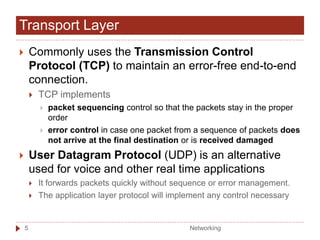
96.
Commonly usesthe Transmission Control
Protocol (TCP) to maintain an error-free end-to-end
connection.
TCP implements
packet sequencing control so that the packets stay in the proper
order
error control in case one packet from a sequence of packets does
not arrive at the final destination or is received damaged
User Datagram Protocol (UDP) is an alternative
used for voice and other real time applications
It forwards packets quickly without sequence or error management.
The application layer protocol will implement any control necessary
Transport Layer
Networking
5
97.
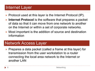
Protocol usedat this layer is the Internet Protocol (IP).
Internet Protocol is the software that prepares a packet
of data so that it can move from one network to another
on the Internet or within a set of corporate networks.
Most important is the addition of source and destination
information
Internet Layer
Network Access Layer
Prepares a data packet (called a frame at this layer) for
transmission from the user workstation to a router
connecting the local area network to the Internet or
another LAN
Networking
6
98.
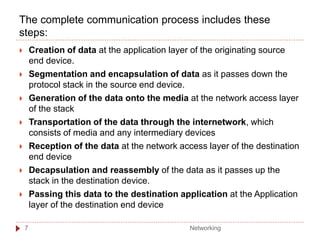
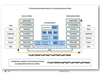
The complete communicationprocess includes these
steps:
Creation of data at the application layer of the originating source
end device.
Segmentation and encapsulation of data as it passes down the
protocol stack in the source end device.
Generation of the data onto the media at the network access layer
of the stack
Transportation of the data through the internetwork, which
consists of media and any intermediary devices
Reception of the data at the network access layer of the destination
end device
Decapsulation and reassembly of the data as it passes up the
stack in the destination device.
Passing this data to the destination application at the Application
layer of the destination end device
Networking
7
99.
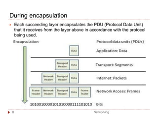
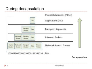
During encapsulation
Eachsucceeding layer encapsulates the PDU (Protocol Data Unit)
that it receives from the layer above in accordance with the protocol
being used.
Networking
8
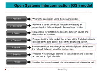
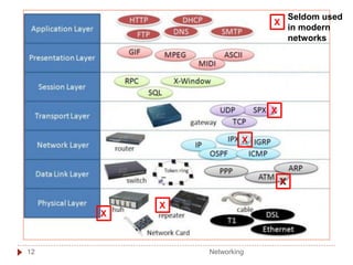
Open Systems Interconnection(OSI) model
Where the application using the network resides
Performs a series of various functions necessary for
presenting the data package to the sender or receiver.
Responsible for establishing sessions between source and
destination applications.
Ensures that the data packet that arrives at the final destination is
identical to the data packet that left the originating station.
Provides services to exchange the individual pieces of data over
the network between identified end devices.
Prepares Network layer packets for transmission and to control
access to the physical media.
Handles the transmission of bits over a communications channel.
Networking
11
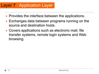
Layer 7 :Application Layer
Provides the interface between the applications.
Exchanges data between programs running on the
source and destination hosts.
Covers applications such as electronic mail, file
transfer systems, remote login systems and Web
browsing.
Networking
13
105.
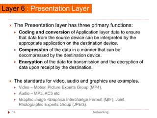
The Presentationlayer has three primary functions:
Coding and conversion of Application layer data to ensure
that data from the source device can be interpreted by the
appropriate application on the destination device.
Compression of the data in a manner that can be
decompressed by the destination device.
Encryption of the data for transmission and the decryption of
data upon receipt by the destination.
The standards for video, audio and graphics are examples.
Video – Motion Picture Experts Group (MP4).
Audio – MP3, AC3 etc
Graphic image -Graphics Interchange Format (GIF), Joint
Photographic Experts Group (JPEG).
Layer 6 : Presentation Layer
Networking
14
106.
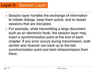
Session layerhandles the exchange of information
to initiate dialogs, keep them active, and to restart
sessions that are disrupted.
For example, while transmitting a large document
such as an electronic book, the session layer may
insert a synchronization point at the end of each
chapter. If any error occurs during transmission, both
sender and receiver can back up to the last
synchronization point and start retransmission from
there.
Layer 5 : Session Layer
Networking
15
107.
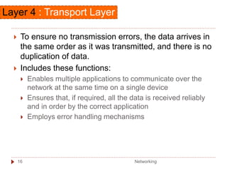
To ensureno transmission errors, the data arrives in
the same order as it was transmitted, and there is no
duplication of data.
Includes these functions:
Enables multiple applications to communicate over the
network at the same time on a single device
Ensures that, if required, all the data is received reliably
and in order by the correct application
Employs error handling mechanisms
Layer 4 : Transport Layer
Networking
16
108.
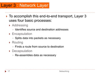
To accomplishthis end-to-end transport, Layer 3
uses four basic processes:
Addressing
Identifies source and destination addresses
Encapsulation
Splits data into packets as necessary
Routing
Finds a route from source to destination
Decapsulation
Re-assembles data as necessary
Layer 3 : Network Layer
Networking
17
109.
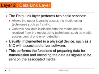
The DataLink layer performs two basic services:
Allows the upper layers to access the media using
techniques such as framing.
Controls how data is placed onto the media and is
received from the media using techniques such as media
access control and error detection.
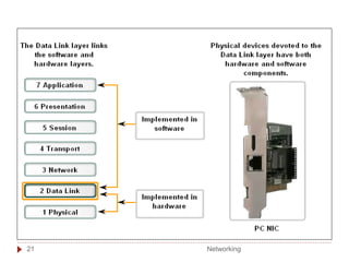
Usually implemented in a physical device, such as a
NIC with associated driver software.
This performs the functions of preparing data for
transmission and encoding the data as signals to be
sent on the associated media.
Layer 2 : Data Link Layer
Networking
18
110.
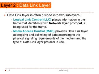
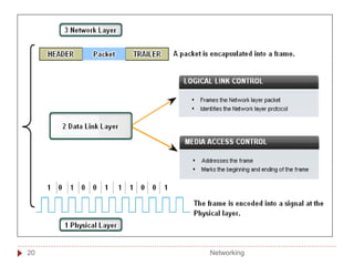
Data Linklayer is often divided into two sublayers:
Logical Link Control (LLC) places information in the
frame that identifies which Network layer protocol is
being used for the frame.
Media Access Control (MAC) provides Data Link layer
addressing and delimiting of data according to the
physical signaling requirements of the medium and the
type of Data Link layer protocol in use.
Layer 2 : Data Link Layer
Networking
19
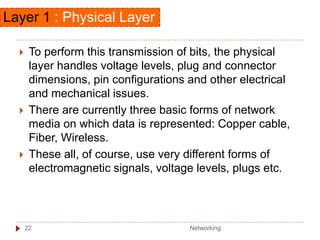
To performthis transmission of bits, the physical
layer handles voltage levels, plug and connector
dimensions, pin configurations and other electrical
and mechanical issues.
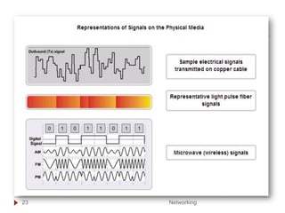
There are currently three basic forms of network
media on which data is represented: Copper cable,
Fiber, Wireless.
These all, of course, use very different forms of
electromagnetic signals, voltage levels, plugs etc.
Layer 1 : Physical Layer
Networking
22
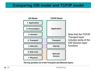
Comparing OSI modeland TCP/IP model
Note that the TCP/IP
Transport layer
includes some of the
OSI Session layer
functions
Networking
25
117.
Unit 1
Introduction tocomputer network
T9 - IP Addresses
IT45103
NETWORKING
Networking
1
118.
Introduction
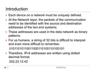
Each deviceon a network must be uniquely defined.
At the Network layer, the packets of the communication
need to be identified with the source and destination
addresses of the two end systems.
These addresses are used in the data network as binary
patterns.
For us humans, a string of 32 bits is difficult to interpret
and even more difficult to remember.
01011010110011000110100110100101
Therefore, IPv4 addresses are written using dotted
decimal format.
202.23.12.42
Networking
2
119.
Dotted decimal
3
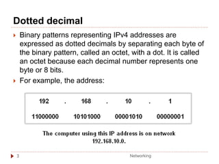
Binarypatterns representing IPv4 addresses are
expressed as dotted decimals by separating each byte of
the binary pattern, called an octet, with a dot. It is called
an octet because each decimal number represents one
byte or 8 bits.
For example, the address:
Networking
120.
Dotted decimal
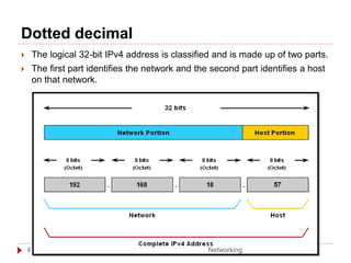
Thelogical 32-bit IPv4 address is classified and is made up of two parts.
The first part identifies the network and the second part identifies a host
on that network.
Networking
4
121.
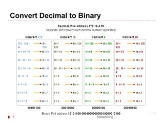
Keep these stepsin mind:
➢Divide the 32 bits into 4 octets.
➢Convert each octet to decimal.
➢Add a "dot" between each
decimal.
Convert Binary to Decimal number
5
In the example, the binary number:
10101100000100000000010000010100
converts to:
172.16.4.20
Networking
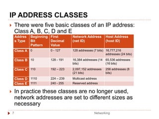
IP ADDRESS CLASSES
There were five basic classes of an IP address:
Class A, B, C, D and E
In practice these classes are no longer used,
network addresses are set to different sizes as
necessary
Addres
s Type
Beginning
Bit
Pattern
First
Decimal
Value
Network Address
(net ID)
Host Address
(host ID)
Class A 0 0 - 127 128 addresses (7 bits) 16,777,216
addresses (24 bits)
Class B 10 128 - 191 16,384 addresses (14
bits)
65,536 addresses
(16 bits)
Class C 110 192 – 223 2,097,152 addresses
(21 bits)
256 addresses (8
bits)
Class D 1110 224 – 239 Multicast address
Class E 1111 240 - 255 Reserved address
Networking
7
124.
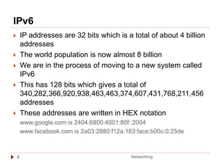
IPv6
8
IP addressesare 32 bits which is a total of about 4 billion
addresses
The world population is now almost 8 billion
We are in the process of moving to a new system called
IPv6
This has 128 bits which gives a total of
340,282,366,920,938,463,463,374,607,431,768,211,456
addresses
These addresses are written in HEX notation
www.google.com is 2404:6800:4001:80f::2004
www.facebook.com is 2a03:2880:f12a:183:face:b00c:0:25de
Networking
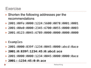
125.
IPv6
Address is128 bits written as 32 hex digits in groups
of 4 separated by colon :
2001:0045:0000:0000:ef01:2345:0000:0abc
Addresses should be written with lower case letters
Leading zeros should be omitted
2001:45:0000:0000:ef01:2345:0000:abc
Groups of all zeros should be omitted
2001:45:0:0:ef01:2345:0:abc
Consecutive all zero groups should be omitted but
only once per address
2001:45::ef01:2345:0:abc
Networking
9


![How Big Brands are Taking Your Traffic in Alberta [Data Inside].pptx](https://cdn.slidesharecdn.com/ss_thumbnails/howbigbrandsaretakingyourtrafficinalbertadatainside-260123180142-42d276f3-thumbnail.jpg?width=640&height=640&fit=bounds)


