Outline
Introduction
Needof Computer Network
Advantages and Disadvantages of Computer Network
Categories of Networks and Internetworks
Network Topologies
Reference Models
Need of Layers
Design Issues of Layers
OSI Model
Functions of each layer
TCP/IP Model
A Comparison of OSI and TCP Reference Model
2
3.
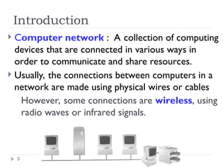
Introduction
Computer network: A collection of computing
devices that are connected in various ways in
order to communicate and share resources.
Usually, the connections between computers in a
network are made using physical wires or cables
However, some connections are wireless, using
radio waves or infrared signals.
3
4.
cont..
A resource maybe:
A file
A folder
A printer
A disk drive
Or just about anything else that exists on a
computer.
4
6
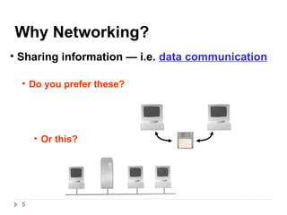
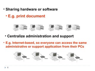
• Sharing hardwareor software
• Centralize administration and support
• E.g. print document
• E.g. Internet-based, so everyone can access the same
administrative or support application from their PCs
7.
Advantages of networks
Sharing devices
Sharing software
Sharing files
Communication
Security is good
Data is easy to backup (Central Management)
Entertainment
Networks are cheaper than “stand-alone PCs.”
7
8.
Disadvantages of networks
Purchasing the network cabling and file servers can be
expensive.
Managing a large network is complicated
If the file server breaks down the files on the file server
become inaccessible.
Viruses can spread to other computers throughout a
computer network.
There is a danger of hacking, particularly with wide area
networks. Security procedures are needed to prevent
such abuse, eg a firewall.
8
9.
Types of Networks
Thereare three types of network:
Local Area Network (LAN)
Wide Area Network (WAN)
Metropolitan Area Network (MAN)
9
10.
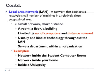
Contd.
Local-area network(LAN) A network that connects a
relatively small number of machines in a relatively close
geographical area.
• i.e. Small network, short distance
• A room, a floor, a building
• Limited by no. of computers and distance covered
• Usually one kind of technology throughout the
LAN
• Serve a department within an organization
• Examples:
• Network inside the Student Computer Room
• Network inside your home
• Inside a University
10
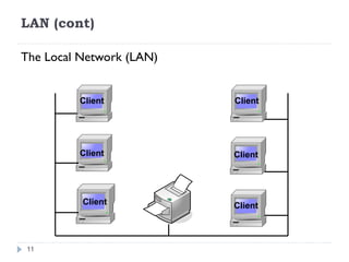
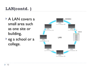
LAN(contd. )
ALAN covers a
small area such
as one site or
building,
eg a school or a
college.
12
13.
Contd.
Wide-area network(WAN) A network that
connects two or more local-area networks over a
potentially large geographic distance
-Often one particular node on a LAN is set up to serve as a
gateway to handle all communication going between that
LAN and other networks
Wide Area Network (WAN) is a computer network
that covers a broad area (i.e., any network whose
communications links cross metropolitan, regional, or
national boundaries). Or, less formally, a network
that uses routers and public communications links
The largest and most well-known example of a WAN
is the Internet.
13
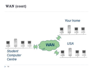
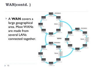
WAN(contd. )
AWAN covers a
large geographical
area. Most WANs
are made from
several LANs
connected together.
15
16.
Contd.
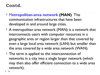
Metropolitan-area network(MAN) The
communication infrastructures that have been
developed in and around large cities.
A metropolitan area network (MAN) is a network that
interconnects users with computer resources in a
geographic area or region larger than that covered by
even a large local area network (LAN) but smaller than
the area covered by a wide area network (WAN).
The term is applied to the interconnection of
networks in a city into a single larger network (which
may then also offer efficient connection to a wide area
network).
16
18
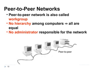
Peer-to-Peer Networks
• Peer-to-peernetwork is also called
workgroup
• No hierarchy among computers all are
equal
• No administrator responsible for the network
Peer-to-peer
19.
19
• Advantages ofpeer-to-peer networks:
• Low cost
• Simple to configure
• User has full accessibility of the computer
• Disadvantages of peer-to-peer networks:
• May have duplication in resources
• Difficult to uphold security policy
• Where peer-to-peer network is appropriate:
• 10 or less users
• No specialized services required
• Security is not an issue
• Only limited growth in the foreseeable future
20.
20
Clients and Servers
•Network Clients
Clients (Workstation
Workstation)
• Computers that request network resources or services
• Network Servers
Servers
• Computers that manage and provide network
resources and services to clients
• Usually have more processing power, memory and
hard disk space than clients
• Run Network Operating System that can manage
not only data, but also users, groups, security, and
applications on the network
• Servers often have a more stringent requirement
on its performance and reliability
21.
internetworking
Communication betweennetworks is called
internetworking.
i.e.
Internetworks
connecting different kinds of networks
routers, gateways
21
22.
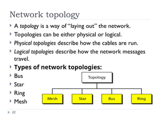
Network topology
Atopology is a way of “laying out” the network.
Topologies can be either physical or logical.
Physical topologies describe how the cables are run.
Logical topologies describe how the network messages
travel.
Types of network topologies:
Bus
Star
Ring
Mesh
22
23.
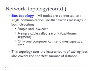
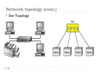
Network topology(contd.)
Bustopology All nodes are connected to a
single communication line that carries messages in
both directions
• Simple and low-cost
• A single cable called a trunk (backbone,
segment)
• Only one computer can send messages at a
time
This topology uses the least amount of cabling, but
also covers the shortest amount of distance.
23
24.
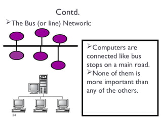
Contd.
The Bus (orline) Network:
Computers are
connected like bus
stops on a main road.
None of them is
more important than
any of the others.
24
25.
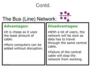
Contd.
The Bus (Line)Network:
Advantages:
•It is cheap as it uses
the least amount of
cable.
•More computers can be
added without disruption.
Disadvantages:
•With a lot of users, the
network will be slow as
data has to travel
through the same central
cable.
•Failure of the central
cable will stop the
network from working.
25
26.
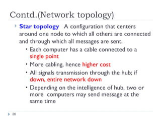
Contd.(Network topology)
Startopology A configuration that centers
around one node to which all others are connected
and through which all messages are sent.
• Each computer has a cable connected to a
single point
• More cabling, hence higher cost
• All signals transmission through the hub; if
down, entire network down
• Depending on the intelligence of hub, two or
more computers may send message at the
same time
26
27.
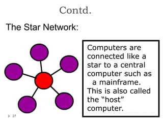
Contd.
The Star Network:
Computersare
connected like a
star to a central
computer such as
a mainframe.
This is also called
the “host”
computer.
27
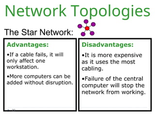
Network Topologies
The StarNetwork:
Advantages:
•If a cable fails, it will
only affect one
workstation.
•More computers can be
added without disruption.
Disadvantages:
•It is more expensive
as it uses the most
cabling.
•Failure of the central
computer will stop the
network from working.
29
30.
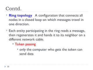
Contd.
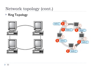
Ring topologyA configuration that connects all
nodes in a closed loop on which messages travel in
one direction.
Each entity participating in the ring reads a message,
then regenerates it and hands it to its neighbor on a
different network cable.
• Token passing
• only the computer who gets the token can
send data
30
31.
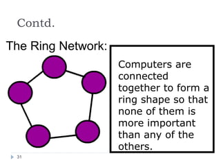
Contd.
The Ring Network:
Computersare
connected
together to form a
ring shape so that
none of them is
more important
than any of the
others.
31
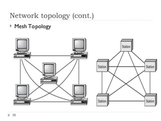
Network topology (cont.)
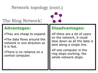
TheRing Network:
Advantages:
•They are cheap to expand.
•The data flows around the
network in one direction so
it is fast.
•There is no reliance on a
central computer.
Disadvantages:
•If there are a lot of users
on the network, it could
slow down as all the data is
sent along a single line.
•If one computer in the
ring stops working, the
whole network stops.
33
34.
Contd.
Mesh topology
Themesh topology is the simplest logical
topology in terms of data flow, but it is the
most complex in terms of physical design.
In this physical topology, each device is
connected to every other device.
This topology is rarely found in LANs, mainly
because of the complexity of the cabling.
34
Advantage and Disadvantage
Advantages of Mesh topology
1) Data can be transmitted from different devices
simultaneously. This topology can withstand high
traffic.
2) Even if one of the components fails there is always
an alternative present. So data transfer doesn’t get
affected.
3) Expansion and modification in topology can be
done without disrupting other nodes.
36
37.
Advantage and Disadvantage
Disadvantages of Mesh topology
1) There are high chances of redundancy in many
of the network connections.
2) Overall cost of this network is way too high as
compared to other network topologies.
3) Set-up and maintenance of this topology is
very difficult. Even administration of the network
is tough.
37
38.
38
The OSI Model
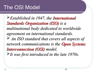
Establishedin 1947, the
Established in 1947, the International
International
Standards Organization (ISO)
Standards Organization (ISO) is a
is a
multinational body dedicated to worldwide
multinational body dedicated to worldwide
agreement on international standards.
agreement on international standards.
An ISO standard that covers all aspects of
An ISO standard that covers all aspects of
network communications is the
network communications is the Open Systems
Open Systems
Interconnection (OSI)
Interconnection (OSI) model.
model.
It was first introduced in the late 1970s.
It was first introduced in the late 1970s.
39.
39
ISO is theorganization.
OSI is the model
Note:
Note:
40.
40
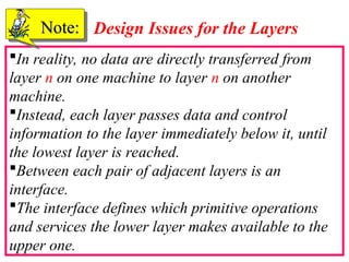
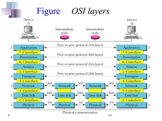
In reality, nodata are directly transferred from
layer n on one machine to layer n on another
machine.
Instead, each layer passes data and control
information to the layer immediately below it, until
the lowest layer is reached.
Between each pair of adjacent layers is an
interface.
The interface defines which primitive operations
and services the lower layer makes available to the
upper one.
Note:
Note: Design Issues for the Layers
41.
41
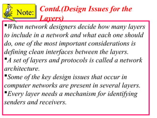
When network designersdecide how many layers
to include in a network and what each one should
do, one of the most important considerations is
defining clean interfaces between the layers.
A set of layers and protocols is called a network
architecture.
Some of the key design issues that occur in
computer networks are present in several layers.
Every layer needs a mechanism for identifying
senders and receivers.
Note:
Note: Contd.(Design Issues for the
Layers)
42.
42
Since a networknormally has many computers,
some of which have multiple processes, a means is
needed for a process on one machine to specify with
whom it wants to talk.
As a consequence of having multiple destinations,
some form of addressing is needed in order to
specify a specific destination.
Another set of design decisions concerns the rules
for data transfer.
In some systems, data only travel in one direction;
in others, data can go both ways.
Note:
Note:
Contd.(Design Issues for the
Layers)
43.
43
Error control isan important issue because
physical communication circuits are not perfect.
Many error-detecting and error-correcting codes
are known, but both ends of the connection must
agree on which one is being used.
In addition, the receiver must have some way of
telling the sender which messages have been
correctly received and which have not.
Note:
Note: Contd. (Design Issues for the
Layers)
44.
44
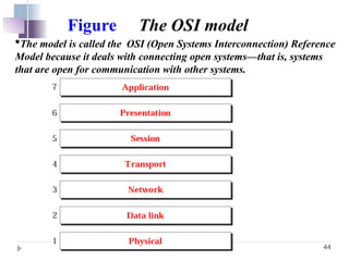
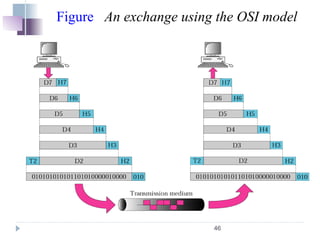
Figure The OSImodel
The model is called the OSI (Open Systems Interconnection) Reference
Model because it deals with connecting open systems—that is, systems
that are open for communication with other systems.
47
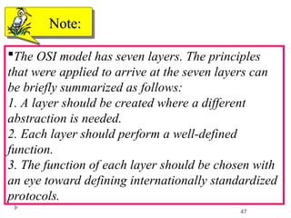
The OSI modelhas seven layers. The principles
that were applied to arrive at the seven layers can
be briefly summarized as follows:
1. A layer should be created where a different
abstraction is needed.
2. Each layer should perform a well-defined
function.
3. The function of each layer should be chosen with
an eye toward defining internationally standardized
protocols.
Note:
Note:
48.
48
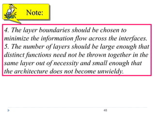
4. The layerboundaries should be chosen to
minimize the information flow across the interfaces.
5. The number of layers should be large enough that
distinct functions need not be thrown together in the
same layer out of necessity and small enough that
the architecture does not become unwieldy.
Note:
Note:
49.
49
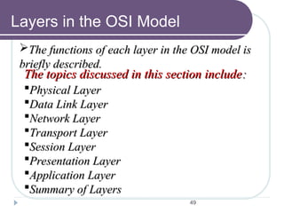
Layers in theOSI Model
The functions of each layer in the OSI model is
The functions of each layer in the OSI model is
briefly described.
briefly described.
The topics discussed in this section include
The topics discussed in this section include:
:
Physical Layer
Physical Layer
Data Link Layer
Data Link Layer
Network Layer
Network Layer
Transport Layer
Transport Layer
Session Layer
Session Layer
Presentation Layer
Presentation Layer
Application Layer
Application Layer
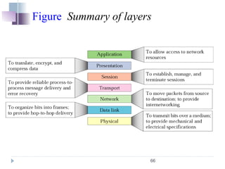
Summary of Layers
Summary of Layers
50.
50
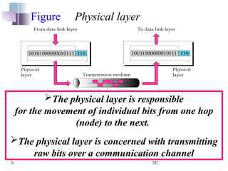
Figure Physical layer
Thephysical layer is responsible
for the movement of individual bits from one hop
(node) to the next.
The physical layer is concerned with transmitting
raw bits over a communication channel
51.
51
The design issueshave to do with making sure that
when one side sends a 1 bit, it is received by the
other side as a 1 bit, not as a 0 bit.
Typical questions here are how many volts should
be used to represent a 1 and how many for a 0, how
many nanoseconds a bit lasts
whether transmission may proceed simultaneously
in both directions, how the initial connection is
established and how it is torn down when both sides
are finished.
Note:
Note:
52.
52
and how manypins the network connector has and
what each pin is used for.
The design issues here largely deal with
mechanical, electrical, and timing interfaces, and
the physical transmission medium, which lies below
the physical layer.
Note:
Note:
53.
53
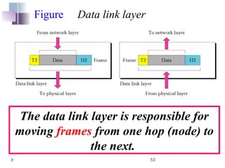
Figure Data linklayer
The data link layer is responsible for
moving frames from one hop (node) to
the next.
54.
54
It accomplishes thistask by having the
sender break up the input data into data
frames (typically a few hundred or a few
thousand bytes) and transmit the frames
sequentially.
If the service is reliable, the receiver
confirms correct receipt of each frame by
sending back an acknowledgement frame.
Note:
Note:
55.
55
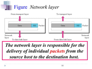
Figure Network layer
Thenetwork layer is responsible for the
delivery of individual packets from the
source host to the destination host.
56.
56
When a packethas to travel from one network to
another to get to its destination, many problems can
arise.
The addressing used by the second network may
be different from the first one.
The second one may not accept the packet at all
because it is too large.
The protocols may differ, and so on.
It is up to the network layer to overcome
all these problems to allow heterogeneous networks
to be interconnected.
Note:
Note:
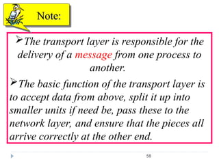
58
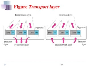
The transport layeris responsible for the
delivery of a message from one process to
another.
The basic function of the transport layer is
to accept data from above, split it up into
smaller units if need be, pass these to the
network layer, and ensure that the pieces all
arrive correctly at the other end.
Note:
Note:
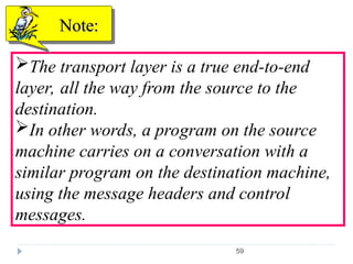
59.
59
The transport layeris a true end-to-end
layer, all the way from the source to the
destination.
In other words, a program on the source
machine carries on a conversation with a
similar program on the destination machine,
using the message headers and control
messages.
Note:
Note:
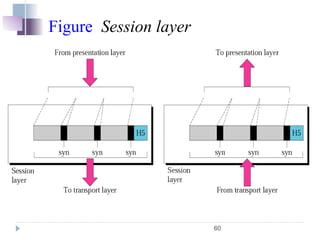
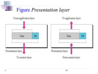
61
The session layerallows users on different
machines to establish sessions between them.
Sessions offer various services, including:
-dialog control (keeping track of whose turn it is to
transmit),
-token management (preventing two parties from
attempting the same critical operation at the same
time), and
-synchronization (checkpointing long transmissions
to allow them to continue from where they were
after a crash).
Note:
Note:
63
Unlike lowerlayers, which are mostly
concerned with moving bits around, the
presentation layer is concerned with the syntax
and semantics of the information transmitted.
To translate, encrypt ,and compress data.
Note:
Note:
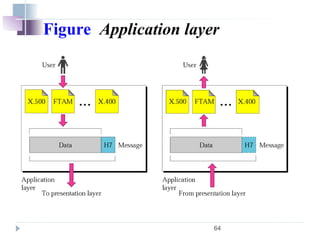
65
The application layercontains a variety of
protocols that are commonly needed by users.
One widely-used application protocol is HTTP
(Hypertext Transfer Protocol), which is the basis for
the World Wide Web.
When a browser wants a Web page, it sends the
name of the page it wants to the server using HTTP.
The server then sends the page back. Other
application protocols are used for file transfer,
electronic mail, and network news.
Note:
Note:
67
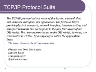
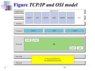
TCP/IP Protocol Suite
The
TheTCP/IP protocol suite
TCP/IP protocol suite is made of five layers: physical, data
is made of five layers: physical, data
link, network, transport, and application. The first four layers
link, network, transport, and application. The first four layers
provide physical standards, network interface, internetworking, and
provide physical standards, network interface, internetworking, and
transport functions that correspond to the first four layers of the
transport functions that correspond to the first four layers of the
OSI model. The three topmost layers in the OSI model, however, are
OSI model. The three topmost layers in the OSI model, however, are
represented in TCP/IP by a single layer called the application
represented in TCP/IP by a single layer called the application
layer.
layer.
The topics discussed in this section include:
The topics discussed in this section include:
Physical and Data Link Layers
Physical and Data Link Layers
Network Layer
Network Layer
Transport Layer
Transport Layer
Application Layer
Application Layer
68.
68
It is agroup of protocols that allows networked
computers to communicate with each other.
It doesn't matter whether:
•they are part of the same network or are attached
to separate networks.
TCP/IP is a platform-independent standard that
bridges the gap between dissimilar computers,
operating systems, and networks
TCP/IP software makes everything seem like one
big network. That is, TCP/IP has the affect of
allowing two separate networks to communicate as
though they were part of the same physical network.
Note:
Note:
69.
69
Some ofthe common TCP/IP application protocols
include :
File Transfer Protocol (FTP),
Telnet,
Domain Name System (DNS),
Simple Mail Transfer Protocol (SMTP),
Multipurpose Internet Mail Extensions (MIME),
Dynamic Host Configuration Protocol (DHCP).
Note:
Note:
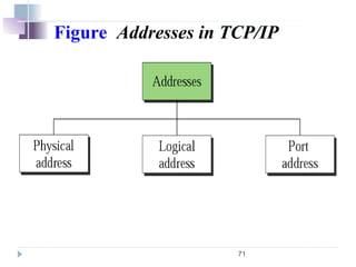
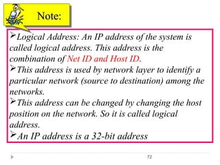
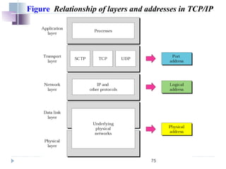
72
Logical Address: AnIP address of the system is
called logical address. This address is the
combination of Net ID and Host ID.
This address is used by network layer to identify a
particular network (source to destination) among the
networks.
This address can be changed by changing the host
position on the network. So it is called logical
address.
An IP address is a 32-bit address
Note:
Note:
73.
73
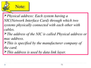
Physical address: Eachsystem having a
NIC(Network Interface Card) through which two
systems physically connected with each other with
cables.
The address of the NIC is called Physical address or
mac address.
This is specified by the manufacturer company of
the card.
This address is used by data link layer.
Note:
Note:
74.
74
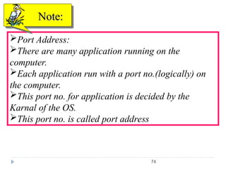
Port Address:
There aremany application running on the
computer.
Each application run with a port no.(logically) on
the computer.
This port no. for application is decided by the
Karnal of the OS.
This port no. is called port address
Note:
Note:
76
The difference betweentwo models is the number
of layers: the OSI model has seven layers and the
TCP/IP has four layers .Both have (inter)network,
transport and Application layers, but the other
layers are different.
The protocols in the OSI model are better
hidden(Stricter boundaries for the protocols) than in
the TCP/IP model and can be replaced relatively
easily as the technology changes.
Note:
Note: A Comparison of OSI and TCP
Reference Model
77.
77
Another difference isin the area of connectionless
and connection oriented communication.
OSI Model supports connection oriented
communication in transport layer, whereas in
network layer it supports both connectionless and
connection oriented.
The TCP/IP model has only one mode in the
network layer but supports both modes in transport
layer.
Note:
Note: Contd.


![[Deck] What's New in Spark-Iceberg Integration via DSV2.pptx](https://cdn.slidesharecdn.com/ss_thumbnails/deckwhatsnewinspark-icebergintegrationviadsv2-260210005337-25955b12-thumbnail.jpg?width=640&height=640&fit=bounds)


