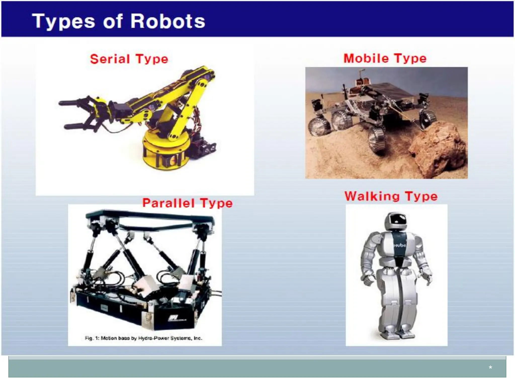
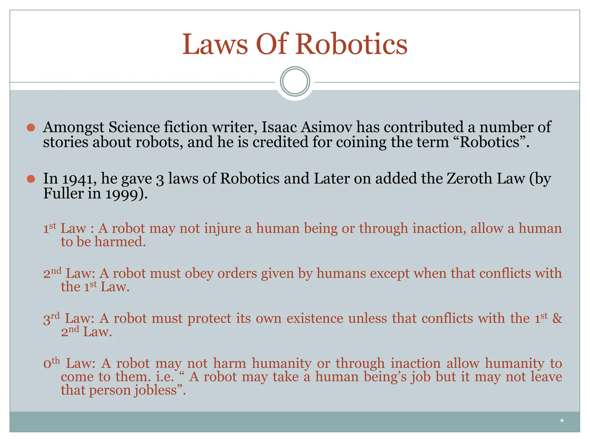
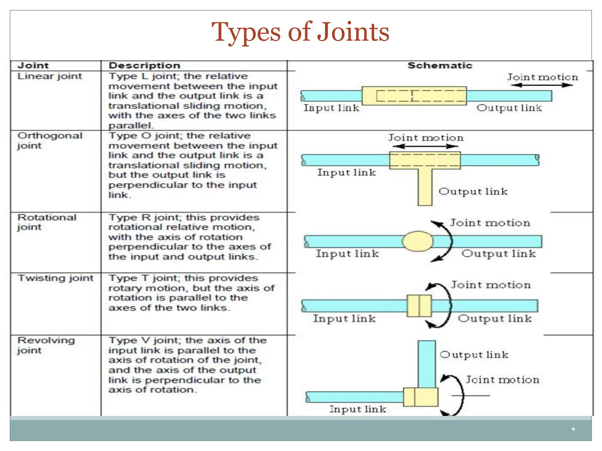
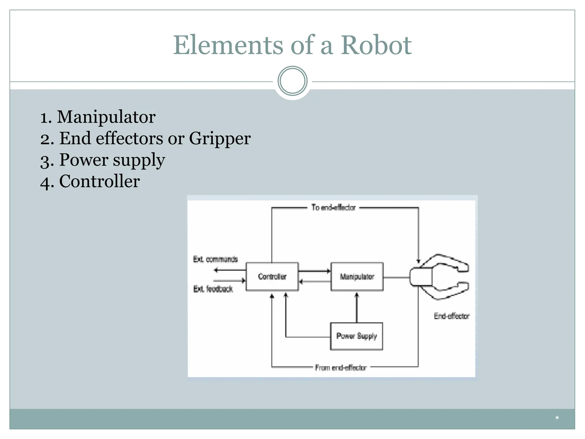
A COMMON VIEW : ROBOTS AS HUMANOIDS
Automation & Robotics
Word Robot Coined By Czech writer Karel Capek in a Play RUR
For this play Čapek invented the word “robot,” deriving it from the Czech word for
forced labour.
*
Automation & Robotics by Mr. Ankur Bhargava
Agenda
⚫Definition of Robot
⚫Definition of Robotics,
⚫Definition of Automation
⚫History of Robotics
⚫Laws of Robotics
⚫Components of Robotic System
⚫Advantages of Robots & Disadvantages of Robots
⚫Classification of Robots on the basis of Geometry
⚫Classification of Robot on the basis of Control
*
ROBOT
⚫ Defined by Robotics Industry Association (RIA) as
“A Re-programmable, multifunctional manipulator designed to move material,
parts, tools or specialized devices through variable programmed motion for a
variety of tasks”
⚫ An industrial robot is a general purpose programmable machine that possesses
certain anthropomorphic features
• The most apparent anthropomorphic feature of an industrial robot is its
mechanical arm, or manipulator
• Robots can perform a variety of tasks such as loading and unloading machine
tools, spot welding automobile bodies, and spray painting
• Robots are typically used as substitutes for human workers in these tasks
⚫ Robots are devices that are programmed to move parts, or to do work with a tool.
⚫ Robotics is a multidisciplinary engineering field dedicated to the development of
autonomous devices, including manipulators and mobile vehicles.
*
BASICS OF ROBOTS
⚫ Robots are very powerful elements of today’s industry. They are capable of performing many
different tasks and operations precisely and do not require common safety and comfort
elements which humans need.
⚫ Robots don’t work as fast as we can or vice versa. Robots maintain their speed over a period of
time.
⚫ A Conventional Robotic Arm & a Crane are almost same in operation, design and structure but
the only difference is that a robot is controlled by a program written by its master while a crane
is controlled by a human operator.
⚫ An industrial robot consists of a mechanical manipulator and a controller to move it and
perform other related functions
• The mechanical manipulator consists of joints and links to position and orient the end of the
manipulator relative to its base
• The controller operates the joints in a coordinated fashion to execute a programmed work cycle
• A robot joint is similar to a human body joint It provides relative movement between two parts of the
body
• Typical industrial robots have five or six joints, Manipulator joints are classified as linear or rotating
*
ROBOTICS
⚫ Robotics is the art, knowledge base and know-how of designing, applying and using
robots in human endeavors.
⚫ Robotic System consists of not just robots but also other devices and systems that
are used together with the robots to perform the necessary tasks.
⚫ A robot is a mechanical device that can perform preprogrammed physical tasks. A
robot may act under the direct control of a human (eg. the robotic arm of the space
shuttle) or autonomously under the control of a pre-programmed computer. Robots
may be used to perform tasks that are too dangerous or difficult for humans to
implement directly (e.g. the space shuttle arm) or may be used to automate
repetitive tasks that can be performed more cheaply by a robot than by the
employment of a human (e.g. automobile production).
⚫ Robots may be used in manufacturing environments, underwater and space
exploration, for aiding the disabled, or even for fun.
*
AUTOMATION
⚫ Automation & Robotics are two closely related technologies.
⚫ In an industrial context, we define Automation as :
“A technology that is concerned with the use of mechanical, electronic
and computer-based systems in the operation and control of
production”.
i.e. Robotics is a form of Industrial Automation.
*
ROBOTICS TIMELINE
⚫ 1922 - Czech author Karel Capek wrote a story called Rossum’s Universal Robots and
introduced the word “Rabota” (meaning worker)
⚫ 1954 - George Devol developed the first programmable Robot.
⚫ 1955 - Denavit and Hartenberg developed the homogenous transformation matrices
⚫ 1962 - UNIMATION was formed, first industrial Robots appeared, and GM installed its
first robot from UNIMATION and named it unimates. (UNIversal and autoMATION
Because of the belief that the robot is a universal tool that can be used for many kinds
of tasks).
⚫ 1973 - Cincinnati Milacron introduced the T3 model robot, which became very popular in
industry.
⚫ 1978 - The Puma (Programmable Universal Machine for Assembly) robot is developed by
Unimation with a General Motors design support
⚫ 1990 - Cincinnati Milacron was acquired by ABB
⚫ 1995- Emerging applications in small robotics and mobile robots drive a second growth
of start-up companies and research
⚫ 2003 - NASA’s Mars Exploration Rovers will launch toward Mars in search of answers
about the history of water on Mars
*
How are robots used?
• Industrial robots do tasks that are hazardous
• Exploratory robots explore environments that are
inhospitable to humans such as space, military
targets or areas of search and rescue operations.
• Assistive robots help handicapped individuals by
assisting with daily tasks including wheelchair
navigation and feeding.
*
*
Laws Of Robotics
⚫ Amongst Science fiction writer, Isaac Asimov has contributed a number of
stories about robots, and he is credited for coining the term “Robotics”.
⚫ In 1941, he gave 3 laws of Robotics and Later on added the Zeroth Law (by
Fuller in 1999).
1st Law : A robot may not injure a human being or through inaction, allow a human
to be harmed.
2nd Law: A robot must obey orders given by humans except when that conflicts with
the 1st Law.
3rd Law: A robot must protect its own existence unless that conflicts with the 1st &
2nd Law.
0th Law: A robot may not harm humanity or through inaction allow humanity to
come to them. i.e. “ A robot may take a human being’s job but it may not leave
that person jobless”.
*
Types of Joints
*
Elements of a Robot
1. Manipulator
2. End effectors or Gripper
3. Power supply
4. Controller
*
Robot Components
Robot system, consists of following elements, which are integrated to form a whole:
⚫ Manipulator / Rover : This is the main body of the Robot and consists of links, joints and
structural elements of the Robot.
⚫ End Effectors : This is the part that generally handles objects, makes connection to other
machines, or performs the required tasks. It can vary in size and complexity from a end-effector
on the space shuttle to a small gripper
⚫ Actuators : Actuators are the muscles of the manipulators. Common types of actuators are
servomotors, stepper motors, pneumatic cylinders etc.
⚫ Sensors : Sensors are used to collect information about the internal state of the robot or to
communicate with the outside environment. Robots are often equipped with external sensory
devices such as a vision system, touch and tactile sensors etc which help to communicate with the
environment
⚫ Controller : The controller receives data from the computer, controls the motions of the
actuator and coordinates these motions with the sensory feedback information.
*
Terminology
⚫ Resolution:-
The resolution of a robot is a feature determined by the design of the control unit and is mainly dependent on
the position feedback sensor. It is important to distinguish the programming resolution from the control
resolution. The programming resolution is the smallest allowable position increment in robot programs and is
referred to as the basic resolution unit (BRU).The control resolution is the smallest change in position that the
feedback device can sense. Best performance is obtained when programming resolution is equal to control
resolution. In this case both resolutions can be replaced with one term: the system resolution.
⚫ Accuracy:-
Accuracy refers to a robot's ability to position its wrist end at a desired target point within the work volume,
and it is defined in terms of spatial resolution. The term accuracy in robotics is often confused with the terms
resolution and repeatability.
Robot accuracy = (BRU + mechanical accuracy)/2
*
Terminology
⚫ Compliance:- Compliance refers to the displacement of the wrist end in response to a force or a
torque exerted against it. A high compliance means that the wrist is displaced a large amount by a
relatively small force. Compliance is important because it may reduces the robot precision of
movement under load as in the case of robot pressing a tool against a work part, the reaction force
of the part may cause deflection of the manipulator.
⚫ Degree of Freedom (D.O.F) - Each joint on the robot introduces a degree of freedom. Each DOF
can be a slider, rotary, or other type of actuator. Robots typically have 5 or 6 degrees of freedom. 3
of the degrees of freedom allow positioning in 3D space, while the other 2or 3 are used for
orientation of the end effector. 6 degrees of freedom are enough to allow the robot to reach all
positions and orientations in 3D space. 5 D.O.F requires a restriction to 2D space, or else it limits
orientations. 5 D.O.F robots are commonly used for handling tools such as arc welders.
⚫ Repeatability: How well a robot can return to the same point.
⚫ Workspace: A volume of space which the end-effector of the manipulator can reach
– Dexterous workspace is the volume of space which the robot can reach with all orientations. That is,
at each point in the dexterous workspace, the end-effector can be arbitrarily oriented.
– The reachable workspace is the volume of space which the robot can reach in at least one orientation
*
Cartesian Configuration
*
Robot Configurations
Some of the commonly used configurations in Robotics are
⚫ Cartesian/Rectangular Gantry(3P) : These Robots are made of
3 Linear joints that orient the end effector, which are usually
followed by additional revolute joints.
*
Cartesian Robot - Work Envelope
*
Cylindrical Configuration
*
Robot Configurations (cont’d)
⚫ Cylindrical (R2P): Cylindrical coordinate Robots have 2 prismatic
joints and one revolute joint.
*
Cylindrical Robot - Work Envelope
*
Polar Configuration
*
Robot Configurations (cont’d)
⚫ Spherical joint (2RP): They follow a spherical coordinate system,
which has one
*
Spherical Robot - Work Envelope
*
Jointed Arm Configuration
*
Robot Configurations (cont’d)
⚫ Articulated/anthropomorphic(3R) :An articulated robot’s joints
are all revolute, similar to a human’s arm.
*
SCARA Configuration
*
Robot Configurations (cont’d)
⚫ Selective Compliance Assembly Robot Arm (SCARA) (2R1P):
They have two revolute joints that are parallel and allow the Robot to
move in a horizontal plane, plus an additional prismatic joint that
moves vertically
*
Advantages & Disadvantages of Robots Configurations
*
Basic components of Robot
⚫ Manipulator: Robot’s arm
⚫ End effector: Gripper tool, special device, fixture to
actually carry out the work
⚫ Power supply: Provides and regulates the energy
⚫ Controller: Initiates, terminates and coordinates the
motion and sequences; accepts input and provides output
● Cartesian/rectangular/gantry (3P)
● Cylindrical (PRP)
● Spherical (P2R)
● Articulated/anthropomorphic (3R)
● Selective Compliance Assembly Robot Arm (SCARA)
Robot Coordinates
Robot Coordinates: Cont.
Robot Reference Frames
● World Reference Frame
● Joint Reference Frame
● Tool Reference Frame
Programming Modes
● Physical Set-up through switches and hard
● Lead Through or Teach Mode with a teach pendant
● Continuous Walk-Through Mode through sampling
and recording the motions
● Software Mode through offline programming
Robot Characteristics
● Payload
● Reach
● Precision (validity
● Repeatability (variability)
Robot Workspace
● Determined empirically or mathematically
Robot Languages
● Interpreter-based or compiler-based
● Micro-Computer Machine Language Level
● Point-to-Point Level
● Primitive Motion Level
● Structured Programming Level
● Task Oriented Level
Robot Applications
● Machine loading
● Pick and place operations
● Welding
● Painting
● Inspection
● Sampling
● Assembly tasks
● Manufacturing
● Medical applications
● Assisting the disabled individuals
● Hazardous environments
● Underwater, space, and inaccessible locations
Other Robots and Applications
● Including but not limited to:
● Roomba
● ASIMO, Bluebotic’s Gilbert, Nestle’s Nesbot, Anybots’s
Monty, Nao robot
● Robots for emergency services, diffusing bombs and
other explosive devices.
● SDA10 dual-arm robot by Motoman, Inc
● Exoskeletal assistive devices such as Human Universal
Load Carrier (HULC)
● Humanoid robots, insect robots, animal robots, walking
machines, and others
● The Grand Challenge
● Animatronics devices
Social Issues
● Worker replacement
● Economic consequences
● Social consequences
● Solutions
Manipulator
Similar to human arm, primary function is
to provide the specific motion
Controller
⚫ Communication and information processing device that
initiates, terminates and coordinates the motions and
sequences of a robot.
⚫ Accepts necessary inputs and provides the output.
⚫ Vary greatly in complexity and design.
⚫ Heart of controller is computer and its solid-state memory.
⚫ Input-output section provides the interface between
controller computer and following parts:
Feedback sensors, Production sensors, Production
machine tools, Teaching devices, Programme
Storage devices, Other computer device hardware.
Robot controller block diagram
Types of control system
⚫ Nonservo: open loop system
⚫ Servo: closed loop system
⚫ Servo-controlled: closed loop system with
continuously controlled path
Nonservo robots: simplest form, also known as limited
sequence robots, pick-and-place robots or fixed stops
robots.
No sensor on the robot arm to provide feedback.
CONTROL METHODS
⚫Non Servo Control
⚪ implemented by setting limits or mechanical stops for each
joint and sequencing the actuation of each joint to accomplish
the cycle
⚪ end point robot, limited sequence robot
⚪ No control over the motion at the intermediate points, only
end points are known
*
⚫ Programming accomplished by
⚪ setting desired sequence of moves
⚪ adjusting end stops for each axis accordingly
⚪ the sequence of moves is controlled by a “squencer”, which
uses feedback received from the end stops to index to next
step in the program
⚫ Low cost and easy to maintain, reliable
⚫ relatively high speed
⚫ repeatability of up to 0.01 inch
⚫ limited flexibility
⚫ typically hydraulic, pneumatic drives
Non Servo Control
*
⚫Servo Control
⚪ Point to point Control
⚪ Continuous Path Control
⚫Closed Loop control used to monitor position,
velocity (other variables) of each joint
*
Point-to-Point Control
⚫ Only the end points are programmed, the path used to connect
the end points are computed by the controller
⚫ user can control velocity, and may permit linear or piece wise
linear motion
⚫ Feedback control is used during motion to ascertain that
individual joints have achieved desired location
⚫ Often used hydraulic drives, recent trend towards servomotors
⚫ loads up to 500lb and large reach
⚫ Applications
⚪ pick and place type operations
⚪ palletizing
⚪ machine loading
*
Continuous Path Controlled
⚫in addition to the control over the endpoints, the
path taken by the end effector can be controlled
⚫Path is controlled by manipulating the joints
throughout the entire motion, via closed loop control
⚫Applications:
⚪ spray painting, polishing, grinding, arc welding
*
Nonservo (open loop)
Linear Actuator
Fixed stop arrangement
Servo (Closed loop) control system
⚫ Signal from controller is dependent on the output of the
system.
⚫ Servomechanism detects and corrects errors.
Servo-controlled (closed loop with control path)
⚫ Memorizes a sequence of arm and end effector’s positions
to follow a programmed motion.
⚫ Transducers are used for feedback.
Advantages of closed loop control
⚫ Higher positional accuracy
⚫ Higher speeds
⚫ Higher torques
⚫ Flexible program control
⚫ Ease of changing programmed points
⚫ Multiple program storage and execution
Disadvantages of closed loop control
⚫ Large capital investment
⚫ Sophisticated programming
⚫ User training
⚫ High-skill maintenance
Accuracy
⚫ Robot’s ability to position its wrist end at desired target
point within the work volume.
⚫ Defined in terms of spatial resolution.
Accuracy….
⚫ Varies within work volume.
⚫ Error map.
⚫ Motion cycle in work range. (mechanical errors)
⚫ Local accuracy (limited work space)
⚫ Global accuracy (full work volume)
⚫ Load being carried by robot.
Repeatability
⚫ Robot’s ability to position its wrist (or end effector) at a
point in space that has previously been taught to the
robot.
⚫ Robots’ ability to return to the programmed point when
commanded to do so.
Compliance
⚫ Compliance of robot manipulator refers to the
displacement of the wrist end in response to a force or
torque exerted against it.
⚫ High compliance- larger displacement by relatively small
force.
⚫ No-load and load conditions.
Robot classification
Robots are classified in six categories:
1.Arm geometry: rectangular, cylindrical, spherical,
jointed-arm
2.Degree of freedom: robot arm, robot wrist
3.Power source: electric, pneumatic, hydraulic, any
combination
4.Type of motion: slew motion, joint-interpolation,
straight line interpolation, circular interpolation
5.Path control: limited-sequence, point-to-point,
continuous path, controlled-path
6.Intelligence level: low level (nonservo), high-
technology (servo)
Arm Geometry
Robot motions and DOF
Types of motion
⚫ Slew motion: Simplest type of motion, Each axis of
manipulator travels at a default speed.
⚫ Joint-interpolated motion: Maximum time is
selected, lower velocities, lower maintenance.
⚫ Straight-line interpolation: Motion in a straight line
using rectangular coordinates, e.g. welding, drilling etc.
⚫ Circular interpolation motion: Circular path is
defined by specifying minimum three points, Arc
contains short shtraight line segments.
Path control
⚫ Limited sequence: No servo control, controlled by limit
switches and/or mechanical stops, used in simple motion
cycles as pick-and –place.
⚫ Pont -to-point: Used in spot welding, grinding, inspection,
assembly etc., Motion may be programmed between any two
points within work volume.
⚫ Controlled path: point-to-point with more precise control.
Good accuracy may be maintained at any point of path.
Path control……
Continuous path motion:
⚫Extension of point-to-point method.
⚫Several thousand points.
⚫Change is speed deos not change the path.
⚫Thousand of point may be memorized.
⚫Used in spray painting or other application where
constant control is required.
Intelligence level
⚫Low technology robots
⚫High technology robots: use of sensors,
artificial intelligence.
Robot Sensors
⚫ Robot sensor is a device or transducer that detects
information about the robot and its surroundings and
transmits into robot’s controller.
⚫ Function of sensor is completed by sending signals.
⚫ Sensors can help robots to:
a) Detect positions and orientation of parts
b)Ensure consistent product quality
c) Discover variations of shape and dimensions of parts
d)Identify unknown obstacles
e) Determine and analyse system malfunctions
Sensor Characteristics
⚫ Cost: if costly, must be balance with reliability, accuracy life
etc.
⚫ Size: Joints range may be affected.
⚫ Weight: May lead to more inertia.
⚫ Type of output: Digital or analog.
⚫ Interfacing:
⚫ Resolution: Minimum step size within the range of
measurement of sensor.
⚫ Sensitivity: Highly sensitive will show larger fluctuations in
output as a result of fluctuation in input.
⚫ Linearity:
⚫ Range: Difference between the smallest and largest input
within which it can operate properly.
⚫ Response time:
Sensor Characteristics
⚫ Frequency response: Frequency response is the range in
which systems’s ability to respond remains relatively high.
Frequency response of the sensor must be considered to
determine whether or not sensor’s response is fast enough
under all operating conditions.
⚫ Reliability: Ratio of how many times a system operates
properly to how many times it is used.
⚫ Accuracy: How close the output of the sensor is to the
expected value.
⚫ Repeatability: Measure of how varied the different outputs
are relative to each other.
Classification of Sensors
General classification in the field of Robotics and
Automation:
⚫Mechanical: for measuring position, shape, velocity,
force, torque, pressure, vibration, strain and mass.
⚫Electrical: for measuring voltage, current,
conductivity etc.
⚫Magnetic: for measuring magnetic field, flux etc.
⚫Thermal: for measuring temperature, conductivity,
specific heat etc.
⚫Others: proximity, photoelectric, radiation, lasers,
optical systems, voice and visual sensing etc.
Classification of Sensors
In specific regard to robots, sensors may be classified as:
⚫Functions performed: under manipulation or acquisition
Attached to the manipulator- touch sensors, force sensors
⚫Location and type of detection: internal, external or interlock
⮚Internal sensors may be mechanical, electric, hydraulic to obtain
feedback information, closed loop, servo controlled system., e.g.
Encoders.
⮚External sensor are physically mounted on robot or process
equipment so that they may be visually seen, e.g. micro switches.
⮚Interlock sensors do not allow an operation to be performed until
certain conditions exist.
•Agriculture
•Automobile
•Construction
•Entertainment
•Health care: hospitals, patient-care, surgery , research, etc.
•Laboratories: science, engineering , etc.
•Law enforcement: surveillance, patrol, etc.
•Manufacturing
•Military: demining, surveillance, attack, etc.
•Mining, excavation, and exploration
•Transportation: air, ground, rail, space, etc.
•Utilities: gas, water, and electric
•Warehouses
Robots in Industry
Industrial Applications of Robots
Material Handling Manipulator
Assembly Manipulator
Spot Welding Manipulator
and/or
• Material handling
• Material transfer
• Machine
loading
unloading
• Spot welding
• Continuous arc
welding
• Spray coating
• Assembly
• Inspection
Robots in Space
NASA Space Station
Robots in Hazardous Environments
TROV in
Antarctica
operating under water
HAZBOT operating in
atmospheres containing
combustible gases
Medical Robots
Roboticassistant
for micro
surgery
Robots in Military
SPLIT STRIKE:
Deployed from a
sub’s hull, Manta
could dispatch tiny
mine-seeking AUVs or
engage in more
explosive combat.
PREDATOR
GLOBAL HAWK
ISTAR
GOLDENEYE
Robots at Home
Sony Aido
Sony SDR-3X Entertainment Robot
Future of Robots: I
Cog Kismet
Artificial Intelligence
Future of Robots: II
Garbage Collection Cart
Robot Work Crews
Autonomy
Future of Robots: III
HONDA Humanoid Robot
Humanoids
Robot end Effectors
• Hand or tool that is attached to the wrist.
• Special tooling that permits the general purpose robot to
perform a particular application.
Categories:
– Grippers
– Tools
Grippers: to grasp and hold objects.
e.g. M/C loading-unloading, picking parts from conveyor,
arranging parts onto pallet.
– End effectors may be Mechanical, Magnetic, Vacuum etc.
– Single gripper, double gripper.
– External grasping, internal grasping.
– Sometimes gripper hold tool rather than work part.
Mechanical Gripper
• An end effector that uses mechanical fingers actuated by a
mechanism to grasp an object.
• Fingers either attached to the mechanism or an integral part of
mechanism.
• Two fingers are sufficient to hold the object.
• Translation of some form of power input into grasping action.
Mechanical gripper……..
Two ways of constraining the part in the gripper:
•Physical constriction of the part within the fingers
•Friction between the fingers and the work part
•Holding part to be soft so as to increase friction and avoidance
of scratches on the work part.
Mechanical gripper……..
Two ways of constraining the part in the gripper:
•Physical constriction of the part within the fingers
•Friction between the fingers and the work part
•Holding part to be soft so as to increase friction and avoidance
of scratches on the work part.
Force analysis
Types of Gripper mechanism
❑ According to the type of finger movement used by gripper,
the grippers can actuate the opening and closing of the
fingers:
• Pivoting movement: fingers rotate about fixed pivots by some
linkage mechanism
• Linear or translational movement: fingers open and close by
moving in parallel to each other accomplished by means of
guide rails
❑ According to type of kinematic device
Types of Gripper mechanism
1. Linkage actuation
Types of Gripper mechanism
2. Gear and rack actuation
Types of Gripper mechanism
3. Cam actuation
Types of Gripper mechanism
4. Screw actuation
Other types of Grippers
Other than mechanical grippers.
1.Vacuum grippers
2.Magnetic grippers
3.Adhesive Grippers
4.Hooks, scoops and other miscellaneous devices
Vacuum cups
• Also called suction cups.
• Objects must be flat, smooth and clean.
• Suction cups are made of elastic material like rubber or soft
plastic.
Vacuum cups
•
Magnetic Grippers
• Very feasible for ferrous metals specially in sheet and plate from.
Advantages:
• Pick up times are fast
• No need to design for one particular object, variation in size of part
is tolerable
• Parts having hole may also be handled
• Require only one surface for gripping
Disadvantages:
• Residual magnetism
• Magnetic attraction tends to penetrate beyond the top layer in
stack
Types: using electromagnets, using permanent magnets
Magnetic Grippers…..
Types: using electromagnets, using permanent magnets
Adhesive Grippers
• Adhesive substance performs the grasping action
• Used to handle fabrics and other light weight materials
• Adhesive substance looses its tackiness on repeated usage
• Adhesive is loaded in the form of continuous ribbon
⮚ Hooks, Scoops ad other devices
⮚ Tools end effectors:
• Spot welding tool, arc welding tool, spray painting nozzle
• Rotating spindle e.g. drilling, grinding etc.
• Heating torches
• Water jet cutting tool
Considerations in gripper selection and design
• Part surface to be grasped must not be enclosed
• Size variation of part must be accounted for (locating problem)
• Consideration to take care of scratching, distorting or dealing with
fragile items
• Larger dimension must be selected to hold the work part
• Gripper fingers should be designed to conform the part shape.
• Weight, speed and acceleration must be taken into account while
designing
Selection of gripper

Unit 1 AR .pdf robotics unit 1 kinematics

  • 1.
    A COMMON VIEW: ROBOTS AS HUMANOIDS Automation & Robotics Word Robot Coined By Czech writer Karel Capek in a Play RUR For this play Čapek invented the word “robot,” deriving it from the Czech word for forced labour. * Automation & Robotics by Mr. Ankur Bhargava
  • 2.
    Agenda ⚫Definition of Robot ⚫Definitionof Robotics, ⚫Definition of Automation ⚫History of Robotics ⚫Laws of Robotics ⚫Components of Robotic System ⚫Advantages of Robots & Disadvantages of Robots ⚫Classification of Robots on the basis of Geometry ⚫Classification of Robot on the basis of Control *
  • 3.
    ROBOT ⚫ Defined byRobotics Industry Association (RIA) as “A Re-programmable, multifunctional manipulator designed to move material, parts, tools or specialized devices through variable programmed motion for a variety of tasks” ⚫ An industrial robot is a general purpose programmable machine that possesses certain anthropomorphic features • The most apparent anthropomorphic feature of an industrial robot is its mechanical arm, or manipulator • Robots can perform a variety of tasks such as loading and unloading machine tools, spot welding automobile bodies, and spray painting • Robots are typically used as substitutes for human workers in these tasks ⚫ Robots are devices that are programmed to move parts, or to do work with a tool. ⚫ Robotics is a multidisciplinary engineering field dedicated to the development of autonomous devices, including manipulators and mobile vehicles. *
  • 4.
    BASICS OF ROBOTS ⚫Robots are very powerful elements of today’s industry. They are capable of performing many different tasks and operations precisely and do not require common safety and comfort elements which humans need. ⚫ Robots don’t work as fast as we can or vice versa. Robots maintain their speed over a period of time. ⚫ A Conventional Robotic Arm & a Crane are almost same in operation, design and structure but the only difference is that a robot is controlled by a program written by its master while a crane is controlled by a human operator. ⚫ An industrial robot consists of a mechanical manipulator and a controller to move it and perform other related functions • The mechanical manipulator consists of joints and links to position and orient the end of the manipulator relative to its base • The controller operates the joints in a coordinated fashion to execute a programmed work cycle • A robot joint is similar to a human body joint It provides relative movement between two parts of the body • Typical industrial robots have five or six joints, Manipulator joints are classified as linear or rotating *
  • 5.
    ROBOTICS ⚫ Robotics isthe art, knowledge base and know-how of designing, applying and using robots in human endeavors. ⚫ Robotic System consists of not just robots but also other devices and systems that are used together with the robots to perform the necessary tasks. ⚫ A robot is a mechanical device that can perform preprogrammed physical tasks. A robot may act under the direct control of a human (eg. the robotic arm of the space shuttle) or autonomously under the control of a pre-programmed computer. Robots may be used to perform tasks that are too dangerous or difficult for humans to implement directly (e.g. the space shuttle arm) or may be used to automate repetitive tasks that can be performed more cheaply by a robot than by the employment of a human (e.g. automobile production). ⚫ Robots may be used in manufacturing environments, underwater and space exploration, for aiding the disabled, or even for fun. *
  • 6.
    AUTOMATION ⚫ Automation &Robotics are two closely related technologies. ⚫ In an industrial context, we define Automation as : “A technology that is concerned with the use of mechanical, electronic and computer-based systems in the operation and control of production”. i.e. Robotics is a form of Industrial Automation. *
  • 7.
    ROBOTICS TIMELINE ⚫ 1922- Czech author Karel Capek wrote a story called Rossum’s Universal Robots and introduced the word “Rabota” (meaning worker) ⚫ 1954 - George Devol developed the first programmable Robot. ⚫ 1955 - Denavit and Hartenberg developed the homogenous transformation matrices ⚫ 1962 - UNIMATION was formed, first industrial Robots appeared, and GM installed its first robot from UNIMATION and named it unimates. (UNIversal and autoMATION Because of the belief that the robot is a universal tool that can be used for many kinds of tasks). ⚫ 1973 - Cincinnati Milacron introduced the T3 model robot, which became very popular in industry. ⚫ 1978 - The Puma (Programmable Universal Machine for Assembly) robot is developed by Unimation with a General Motors design support ⚫ 1990 - Cincinnati Milacron was acquired by ABB ⚫ 1995- Emerging applications in small robotics and mobile robots drive a second growth of start-up companies and research ⚫ 2003 - NASA’s Mars Exploration Rovers will launch toward Mars in search of answers about the history of water on Mars *
  • 8.
    How are robotsused? • Industrial robots do tasks that are hazardous • Exploratory robots explore environments that are inhospitable to humans such as space, military targets or areas of search and rescue operations. • Assistive robots help handicapped individuals by assisting with daily tasks including wheelchair navigation and feeding. *
  • 9.
  • 10.
    Laws Of Robotics ⚫Amongst Science fiction writer, Isaac Asimov has contributed a number of stories about robots, and he is credited for coining the term “Robotics”. ⚫ In 1941, he gave 3 laws of Robotics and Later on added the Zeroth Law (by Fuller in 1999). 1st Law : A robot may not injure a human being or through inaction, allow a human to be harmed. 2nd Law: A robot must obey orders given by humans except when that conflicts with the 1st Law. 3rd Law: A robot must protect its own existence unless that conflicts with the 1st & 2nd Law. 0th Law: A robot may not harm humanity or through inaction allow humanity to come to them. i.e. “ A robot may take a human being’s job but it may not leave that person jobless”. *
  • 11.
  • 12.
    Elements of aRobot 1. Manipulator 2. End effectors or Gripper 3. Power supply 4. Controller *
  • 13.
    Robot Components Robot system,consists of following elements, which are integrated to form a whole: ⚫ Manipulator / Rover : This is the main body of the Robot and consists of links, joints and structural elements of the Robot. ⚫ End Effectors : This is the part that generally handles objects, makes connection to other machines, or performs the required tasks. It can vary in size and complexity from a end-effector on the space shuttle to a small gripper ⚫ Actuators : Actuators are the muscles of the manipulators. Common types of actuators are servomotors, stepper motors, pneumatic cylinders etc. ⚫ Sensors : Sensors are used to collect information about the internal state of the robot or to communicate with the outside environment. Robots are often equipped with external sensory devices such as a vision system, touch and tactile sensors etc which help to communicate with the environment ⚫ Controller : The controller receives data from the computer, controls the motions of the actuator and coordinates these motions with the sensory feedback information. *
  • 14.
    Terminology ⚫ Resolution:- The resolutionof a robot is a feature determined by the design of the control unit and is mainly dependent on the position feedback sensor. It is important to distinguish the programming resolution from the control resolution. The programming resolution is the smallest allowable position increment in robot programs and is referred to as the basic resolution unit (BRU).The control resolution is the smallest change in position that the feedback device can sense. Best performance is obtained when programming resolution is equal to control resolution. In this case both resolutions can be replaced with one term: the system resolution. ⚫ Accuracy:- Accuracy refers to a robot's ability to position its wrist end at a desired target point within the work volume, and it is defined in terms of spatial resolution. The term accuracy in robotics is often confused with the terms resolution and repeatability. Robot accuracy = (BRU + mechanical accuracy)/2 *
  • 15.
    Terminology ⚫ Compliance:- Compliancerefers to the displacement of the wrist end in response to a force or a torque exerted against it. A high compliance means that the wrist is displaced a large amount by a relatively small force. Compliance is important because it may reduces the robot precision of movement under load as in the case of robot pressing a tool against a work part, the reaction force of the part may cause deflection of the manipulator. ⚫ Degree of Freedom (D.O.F) - Each joint on the robot introduces a degree of freedom. Each DOF can be a slider, rotary, or other type of actuator. Robots typically have 5 or 6 degrees of freedom. 3 of the degrees of freedom allow positioning in 3D space, while the other 2or 3 are used for orientation of the end effector. 6 degrees of freedom are enough to allow the robot to reach all positions and orientations in 3D space. 5 D.O.F requires a restriction to 2D space, or else it limits orientations. 5 D.O.F robots are commonly used for handling tools such as arc welders. ⚫ Repeatability: How well a robot can return to the same point. ⚫ Workspace: A volume of space which the end-effector of the manipulator can reach – Dexterous workspace is the volume of space which the robot can reach with all orientations. That is, at each point in the dexterous workspace, the end-effector can be arbitrarily oriented. – The reachable workspace is the volume of space which the robot can reach in at least one orientation *
  • 16.
  • 17.
    Robot Configurations Some ofthe commonly used configurations in Robotics are ⚫ Cartesian/Rectangular Gantry(3P) : These Robots are made of 3 Linear joints that orient the end effector, which are usually followed by additional revolute joints. *
  • 18.
    Cartesian Robot -Work Envelope *
  • 19.
  • 20.
    Robot Configurations (cont’d) ⚫Cylindrical (R2P): Cylindrical coordinate Robots have 2 prismatic joints and one revolute joint. *
  • 21.
    Cylindrical Robot -Work Envelope *
  • 22.
  • 23.
    Robot Configurations (cont’d) ⚫Spherical joint (2RP): They follow a spherical coordinate system, which has one *
  • 24.
    Spherical Robot -Work Envelope *
  • 25.
  • 26.
    Robot Configurations (cont’d) ⚫Articulated/anthropomorphic(3R) :An articulated robot’s joints are all revolute, similar to a human’s arm. *
  • 27.
  • 28.
    Robot Configurations (cont’d) ⚫Selective Compliance Assembly Robot Arm (SCARA) (2R1P): They have two revolute joints that are parallel and allow the Robot to move in a horizontal plane, plus an additional prismatic joint that moves vertically *
  • 29.
    Advantages & Disadvantagesof Robots Configurations *
  • 30.
  • 31.
    Basic components ofRobot ⚫ Manipulator: Robot’s arm ⚫ End effector: Gripper tool, special device, fixture to actually carry out the work ⚫ Power supply: Provides and regulates the energy ⚫ Controller: Initiates, terminates and coordinates the motion and sequences; accepts input and provides output
  • 32.
    ● Cartesian/rectangular/gantry (3P) ●Cylindrical (PRP) ● Spherical (P2R) ● Articulated/anthropomorphic (3R) ● Selective Compliance Assembly Robot Arm (SCARA) Robot Coordinates
  • 33.
  • 34.
    Robot Reference Frames ●World Reference Frame ● Joint Reference Frame ● Tool Reference Frame
  • 35.
    Programming Modes ● PhysicalSet-up through switches and hard ● Lead Through or Teach Mode with a teach pendant ● Continuous Walk-Through Mode through sampling and recording the motions ● Software Mode through offline programming
  • 36.
    Robot Characteristics ● Payload ●Reach ● Precision (validity ● Repeatability (variability)
  • 37.
    Robot Workspace ● Determinedempirically or mathematically
  • 38.
    Robot Languages ● Interpreter-basedor compiler-based ● Micro-Computer Machine Language Level ● Point-to-Point Level ● Primitive Motion Level ● Structured Programming Level ● Task Oriented Level
  • 39.
    Robot Applications ● Machineloading ● Pick and place operations ● Welding ● Painting ● Inspection ● Sampling ● Assembly tasks ● Manufacturing ● Medical applications ● Assisting the disabled individuals ● Hazardous environments ● Underwater, space, and inaccessible locations
  • 40.
    Other Robots andApplications ● Including but not limited to: ● Roomba ● ASIMO, Bluebotic’s Gilbert, Nestle’s Nesbot, Anybots’s Monty, Nao robot ● Robots for emergency services, diffusing bombs and other explosive devices. ● SDA10 dual-arm robot by Motoman, Inc ● Exoskeletal assistive devices such as Human Universal Load Carrier (HULC) ● Humanoid robots, insect robots, animal robots, walking machines, and others ● The Grand Challenge ● Animatronics devices
  • 41.
    Social Issues ● Workerreplacement ● Economic consequences ● Social consequences ● Solutions
  • 42.
    Manipulator Similar to humanarm, primary function is to provide the specific motion
  • 43.
    Controller ⚫ Communication andinformation processing device that initiates, terminates and coordinates the motions and sequences of a robot. ⚫ Accepts necessary inputs and provides the output. ⚫ Vary greatly in complexity and design. ⚫ Heart of controller is computer and its solid-state memory. ⚫ Input-output section provides the interface between controller computer and following parts: Feedback sensors, Production sensors, Production machine tools, Teaching devices, Programme Storage devices, Other computer device hardware.
  • 44.
  • 45.
    Types of controlsystem ⚫ Nonservo: open loop system ⚫ Servo: closed loop system ⚫ Servo-controlled: closed loop system with continuously controlled path Nonservo robots: simplest form, also known as limited sequence robots, pick-and-place robots or fixed stops robots. No sensor on the robot arm to provide feedback.
  • 46.
    CONTROL METHODS ⚫Non ServoControl ⚪ implemented by setting limits or mechanical stops for each joint and sequencing the actuation of each joint to accomplish the cycle ⚪ end point robot, limited sequence robot ⚪ No control over the motion at the intermediate points, only end points are known *
  • 47.
    ⚫ Programming accomplishedby ⚪ setting desired sequence of moves ⚪ adjusting end stops for each axis accordingly ⚪ the sequence of moves is controlled by a “squencer”, which uses feedback received from the end stops to index to next step in the program ⚫ Low cost and easy to maintain, reliable ⚫ relatively high speed ⚫ repeatability of up to 0.01 inch ⚫ limited flexibility ⚫ typically hydraulic, pneumatic drives Non Servo Control *
  • 48.
    ⚫Servo Control ⚪ Pointto point Control ⚪ Continuous Path Control ⚫Closed Loop control used to monitor position, velocity (other variables) of each joint *
  • 49.
    Point-to-Point Control ⚫ Onlythe end points are programmed, the path used to connect the end points are computed by the controller ⚫ user can control velocity, and may permit linear or piece wise linear motion ⚫ Feedback control is used during motion to ascertain that individual joints have achieved desired location ⚫ Often used hydraulic drives, recent trend towards servomotors ⚫ loads up to 500lb and large reach ⚫ Applications ⚪ pick and place type operations ⚪ palletizing ⚪ machine loading *
  • 50.
    Continuous Path Controlled ⚫inaddition to the control over the endpoints, the path taken by the end effector can be controlled ⚫Path is controlled by manipulating the joints throughout the entire motion, via closed loop control ⚫Applications: ⚪ spray painting, polishing, grinding, arc welding *
  • 51.
  • 52.
  • 53.
  • 54.
    Servo (Closed loop)control system ⚫ Signal from controller is dependent on the output of the system. ⚫ Servomechanism detects and corrects errors.
  • 55.
    Servo-controlled (closed loopwith control path) ⚫ Memorizes a sequence of arm and end effector’s positions to follow a programmed motion. ⚫ Transducers are used for feedback.
  • 56.
    Advantages of closedloop control ⚫ Higher positional accuracy ⚫ Higher speeds ⚫ Higher torques ⚫ Flexible program control ⚫ Ease of changing programmed points ⚫ Multiple program storage and execution Disadvantages of closed loop control ⚫ Large capital investment ⚫ Sophisticated programming ⚫ User training ⚫ High-skill maintenance
  • 57.
    Accuracy ⚫ Robot’s abilityto position its wrist end at desired target point within the work volume. ⚫ Defined in terms of spatial resolution.
  • 58.
    Accuracy…. ⚫ Varies withinwork volume. ⚫ Error map. ⚫ Motion cycle in work range. (mechanical errors) ⚫ Local accuracy (limited work space) ⚫ Global accuracy (full work volume) ⚫ Load being carried by robot.
  • 59.
    Repeatability ⚫ Robot’s abilityto position its wrist (or end effector) at a point in space that has previously been taught to the robot. ⚫ Robots’ ability to return to the programmed point when commanded to do so.
  • 60.
    Compliance ⚫ Compliance ofrobot manipulator refers to the displacement of the wrist end in response to a force or torque exerted against it. ⚫ High compliance- larger displacement by relatively small force. ⚫ No-load and load conditions.
  • 61.
    Robot classification Robots areclassified in six categories: 1.Arm geometry: rectangular, cylindrical, spherical, jointed-arm 2.Degree of freedom: robot arm, robot wrist 3.Power source: electric, pneumatic, hydraulic, any combination 4.Type of motion: slew motion, joint-interpolation, straight line interpolation, circular interpolation 5.Path control: limited-sequence, point-to-point, continuous path, controlled-path 6.Intelligence level: low level (nonservo), high- technology (servo)
  • 62.
  • 63.
  • 64.
  • 65.
  • 66.
  • 67.
    Types of motion ⚫Slew motion: Simplest type of motion, Each axis of manipulator travels at a default speed. ⚫ Joint-interpolated motion: Maximum time is selected, lower velocities, lower maintenance. ⚫ Straight-line interpolation: Motion in a straight line using rectangular coordinates, e.g. welding, drilling etc. ⚫ Circular interpolation motion: Circular path is defined by specifying minimum three points, Arc contains short shtraight line segments.
  • 68.
    Path control ⚫ Limitedsequence: No servo control, controlled by limit switches and/or mechanical stops, used in simple motion cycles as pick-and –place. ⚫ Pont -to-point: Used in spot welding, grinding, inspection, assembly etc., Motion may be programmed between any two points within work volume. ⚫ Controlled path: point-to-point with more precise control. Good accuracy may be maintained at any point of path.
  • 69.
    Path control…… Continuous pathmotion: ⚫Extension of point-to-point method. ⚫Several thousand points. ⚫Change is speed deos not change the path. ⚫Thousand of point may be memorized. ⚫Used in spray painting or other application where constant control is required.
  • 70.
    Intelligence level ⚫Low technologyrobots ⚫High technology robots: use of sensors, artificial intelligence.
  • 71.
    Robot Sensors ⚫ Robotsensor is a device or transducer that detects information about the robot and its surroundings and transmits into robot’s controller. ⚫ Function of sensor is completed by sending signals. ⚫ Sensors can help robots to: a) Detect positions and orientation of parts b)Ensure consistent product quality c) Discover variations of shape and dimensions of parts d)Identify unknown obstacles e) Determine and analyse system malfunctions
  • 72.
    Sensor Characteristics ⚫ Cost:if costly, must be balance with reliability, accuracy life etc. ⚫ Size: Joints range may be affected. ⚫ Weight: May lead to more inertia. ⚫ Type of output: Digital or analog. ⚫ Interfacing: ⚫ Resolution: Minimum step size within the range of measurement of sensor. ⚫ Sensitivity: Highly sensitive will show larger fluctuations in output as a result of fluctuation in input. ⚫ Linearity: ⚫ Range: Difference between the smallest and largest input within which it can operate properly. ⚫ Response time:
  • 73.
    Sensor Characteristics ⚫ Frequencyresponse: Frequency response is the range in which systems’s ability to respond remains relatively high. Frequency response of the sensor must be considered to determine whether or not sensor’s response is fast enough under all operating conditions. ⚫ Reliability: Ratio of how many times a system operates properly to how many times it is used. ⚫ Accuracy: How close the output of the sensor is to the expected value. ⚫ Repeatability: Measure of how varied the different outputs are relative to each other.
  • 74.
    Classification of Sensors Generalclassification in the field of Robotics and Automation: ⚫Mechanical: for measuring position, shape, velocity, force, torque, pressure, vibration, strain and mass. ⚫Electrical: for measuring voltage, current, conductivity etc. ⚫Magnetic: for measuring magnetic field, flux etc. ⚫Thermal: for measuring temperature, conductivity, specific heat etc. ⚫Others: proximity, photoelectric, radiation, lasers, optical systems, voice and visual sensing etc.
  • 75.
    Classification of Sensors Inspecific regard to robots, sensors may be classified as: ⚫Functions performed: under manipulation or acquisition Attached to the manipulator- touch sensors, force sensors ⚫Location and type of detection: internal, external or interlock ⮚Internal sensors may be mechanical, electric, hydraulic to obtain feedback information, closed loop, servo controlled system., e.g. Encoders. ⮚External sensor are physically mounted on robot or process equipment so that they may be visually seen, e.g. micro switches. ⮚Interlock sensors do not allow an operation to be performed until certain conditions exist.
  • 76.
    •Agriculture •Automobile •Construction •Entertainment •Health care: hospitals,patient-care, surgery , research, etc. •Laboratories: science, engineering , etc. •Law enforcement: surveillance, patrol, etc. •Manufacturing •Military: demining, surveillance, attack, etc. •Mining, excavation, and exploration •Transportation: air, ground, rail, space, etc. •Utilities: gas, water, and electric •Warehouses Robots in Industry
  • 77.
    Industrial Applications ofRobots Material Handling Manipulator Assembly Manipulator Spot Welding Manipulator and/or • Material handling • Material transfer • Machine loading unloading • Spot welding • Continuous arc welding • Spray coating • Assembly • Inspection
  • 78.
    Robots in Space NASASpace Station
  • 79.
    Robots in HazardousEnvironments TROV in Antarctica operating under water HAZBOT operating in atmospheres containing combustible gases
  • 80.
  • 81.
    Robots in Military SPLITSTRIKE: Deployed from a sub’s hull, Manta could dispatch tiny mine-seeking AUVs or engage in more explosive combat. PREDATOR GLOBAL HAWK ISTAR GOLDENEYE
  • 82.
    Robots at Home SonyAido Sony SDR-3X Entertainment Robot
  • 83.
    Future of Robots:I Cog Kismet Artificial Intelligence
  • 84.
    Future of Robots:II Garbage Collection Cart Robot Work Crews Autonomy
  • 85.
    Future of Robots:III HONDA Humanoid Robot Humanoids
  • 86.
    Robot end Effectors •Hand or tool that is attached to the wrist. • Special tooling that permits the general purpose robot to perform a particular application. Categories: – Grippers – Tools Grippers: to grasp and hold objects. e.g. M/C loading-unloading, picking parts from conveyor, arranging parts onto pallet. – End effectors may be Mechanical, Magnetic, Vacuum etc. – Single gripper, double gripper. – External grasping, internal grasping. – Sometimes gripper hold tool rather than work part.
  • 87.
    Mechanical Gripper • Anend effector that uses mechanical fingers actuated by a mechanism to grasp an object. • Fingers either attached to the mechanism or an integral part of mechanism. • Two fingers are sufficient to hold the object. • Translation of some form of power input into grasping action.
  • 88.
    Mechanical gripper…….. Two waysof constraining the part in the gripper: •Physical constriction of the part within the fingers •Friction between the fingers and the work part •Holding part to be soft so as to increase friction and avoidance of scratches on the work part.
  • 89.
    Mechanical gripper…….. Two waysof constraining the part in the gripper: •Physical constriction of the part within the fingers •Friction between the fingers and the work part •Holding part to be soft so as to increase friction and avoidance of scratches on the work part.
  • 90.
  • 91.
    Types of Grippermechanism ❑ According to the type of finger movement used by gripper, the grippers can actuate the opening and closing of the fingers: • Pivoting movement: fingers rotate about fixed pivots by some linkage mechanism • Linear or translational movement: fingers open and close by moving in parallel to each other accomplished by means of guide rails ❑ According to type of kinematic device
  • 92.
    Types of Grippermechanism 1. Linkage actuation
  • 93.
    Types of Grippermechanism 2. Gear and rack actuation
  • 94.
    Types of Grippermechanism 3. Cam actuation
  • 95.
    Types of Grippermechanism 4. Screw actuation
  • 96.
    Other types ofGrippers Other than mechanical grippers. 1.Vacuum grippers 2.Magnetic grippers 3.Adhesive Grippers 4.Hooks, scoops and other miscellaneous devices
  • 97.
    Vacuum cups • Alsocalled suction cups. • Objects must be flat, smooth and clean. • Suction cups are made of elastic material like rubber or soft plastic.
  • 98.
  • 99.
    Magnetic Grippers • Veryfeasible for ferrous metals specially in sheet and plate from. Advantages: • Pick up times are fast • No need to design for one particular object, variation in size of part is tolerable • Parts having hole may also be handled • Require only one surface for gripping Disadvantages: • Residual magnetism • Magnetic attraction tends to penetrate beyond the top layer in stack Types: using electromagnets, using permanent magnets
  • 100.
    Magnetic Grippers….. Types: usingelectromagnets, using permanent magnets
  • 101.
    Adhesive Grippers • Adhesivesubstance performs the grasping action • Used to handle fabrics and other light weight materials • Adhesive substance looses its tackiness on repeated usage • Adhesive is loaded in the form of continuous ribbon ⮚ Hooks, Scoops ad other devices ⮚ Tools end effectors: • Spot welding tool, arc welding tool, spray painting nozzle • Rotating spindle e.g. drilling, grinding etc. • Heating torches • Water jet cutting tool
  • 102.
    Considerations in gripperselection and design • Part surface to be grasped must not be enclosed • Size variation of part must be accounted for (locating problem) • Consideration to take care of scratching, distorting or dealing with fragile items • Larger dimension must be selected to hold the work part • Gripper fingers should be designed to conform the part shape. • Weight, speed and acceleration must be taken into account while designing
  • 103.
  • 104.