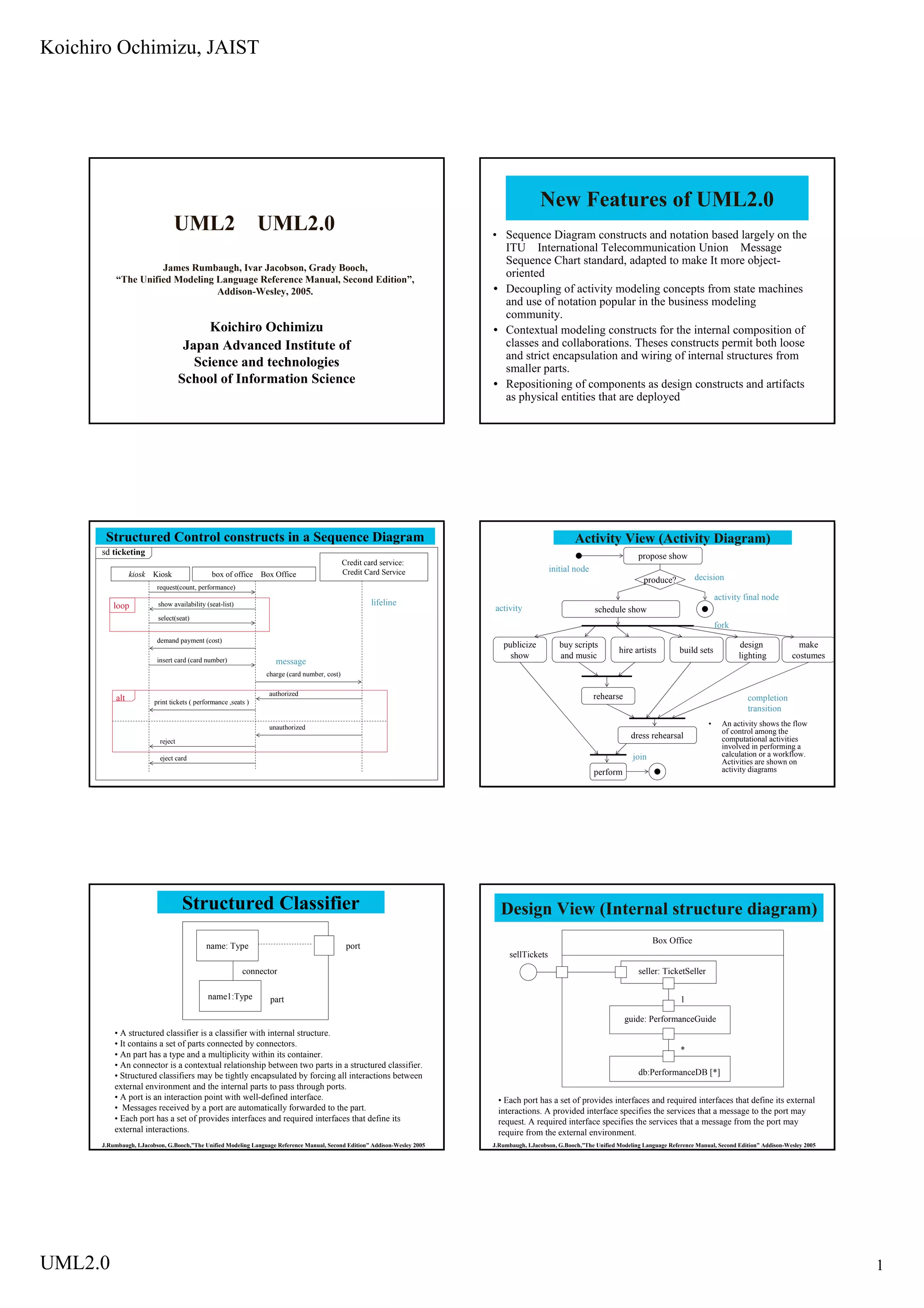
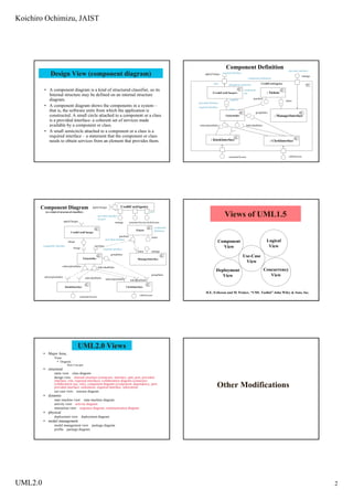
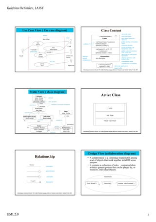
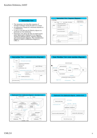
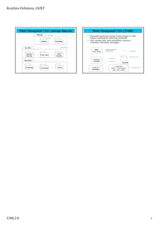
The document summarizes new features of UML 2.0 including improved sequence diagram constructs based on ITU standards, decoupling of activity modeling concepts from state machines, and contextual modeling constructs that allow for loose and strict encapsulation of internal structures. It also provides examples of various UML diagrams like class, sequence, state machine, component, and package diagrams and explains concepts like profiles, stereotypes, constraints and tagged values.
Koichiro Ochimizu of JAIST on UML2.0 Features and Diagrams
1. Koichiro Ochimizu, JAIST
New Features of UML2.0
UML2 UML2.0 • Sequence Diagram constructs and notation based largely on the
ITU International Telecommunication Union Message
Sequence Chart standard, adapted to make It more object-
James Rumbaugh, Ivar Jacobson, Grady Booch,
oriented
“The Unified Modeling Language Reference Manual, Second Edition”,
Decoupling of activity modeling concepts from state machines
Addison-Wesley, 2005.
and use of notation popular in the business modeling
community.
Koichiro Ochimizu Contextual modeling constructs for the internal composition of
classes and collaborations. Theses constructs permit both loose
Japan Advanced Institute of
and strict encapsulation and wiring of internal structures from
Science and technologies smaller parts.
School of Information Science Repositioning of components as design constructs and artifacts
as physical entities that are deployed
Structured Control constructs in a Sequence Diagram Activity View (Activity Diagram)
sd ticketing propose show
Credit card service:
initial node
Credit Card Service
kiosk Kiosk box of office Box Office decision
produce?
request(count, performance)
activity final node
lifeline
show availability (seat-list)
loop activity schedule show
select(seat)
fork
demand payment (cost)
publicize buy scripts design make
hire artists build sets
show and music lighting costumes
insert card (card number) message
charge (card number, cost)
authorized rehearse
alt completion
print tickets ( performance ,seats )
transition
• An activity shows the flow
unauthorized
of control among the
dress rehearsal computational activities
reject
involved in performing a
calculation or a workflow.
join
eject card
Activities are shown on
activity diagrams
perform
Structured Classifier Design View (Internal structure diagram)
Box Office
name: Type port
sellTickets
connector seller: TicketSeller
name1:Type part 1
guide: PerformanceGuide
• A structured classifier is a classifier with internal structure.
• It contains a set of parts connected by connectors.
*
• An part has a type and a multiplicity within its container.
• An connector is a contextual relationship between two parts in a structured classifier.
db:PerformanceDB [*]
• Structured classifiers may be tightly encapsulated by forcing all interactions between
external environment and the internal parts to pass through ports.
• A port is an interaction point with well-defined interface. • Each port has a set of provides interfaces and required interfaces that define its external
• Messages received by a port are automatically forwarded to the part. interactions. A provided interface specifies the services that a message to the port may
• Each port has a set of provides interfaces and required interfaces that define its request. A required interface specifies the services that a message from the port may
external interactions. require from the external environment.
J.Rumbaugh, I.Jacobson, G.Booch,”The Unified Modeling Language Reference Manual, Second Edition” Addison-Wesley 2005 J.Rumbaugh, I.Jacobson, G.Booch,”The Unified Modeling Language Reference Manual, Second Edition” Addison-Wesley 2005
UML2.0 1
2. Koichiro Ochimizu, JAIST
Component Definition provides interface
Design View (component diagram) applyCharges required interface
manage
component definition
port CreditCardAgency
delegation connector
• A component diagram is a kind of structured classifier, so its component
:CreditCardChargers : Tickets
use
Internal structure may be defined on an internal structure
purchase
diagram. supplier status
provided interface
• A component diagram shows the components in a system – required interface
client
that is, the software units from which the application is groupSales
constructed. A small circle attached to a component or a class : ManagerInterface
:TicketSeller
is a provided interface- a coherent set of services made
available by a component or class. subscriptionSales IndividualSales
• A small semicircle attached to a component or a class is a
required interface – a statement that the component or class
: KioskInterface
needs to obtain services from an element that provides them. : ClerkInterface
clerkAccess
customerAccess
Component Diagram CreditCardAgency
applyCharges
port
(is a kind of structured classifier)
Views of UML1.5
provided interface
on port
applyCharges manage customerAccess clerkAcsess
component
Tickets definition
CreditCardCharges
purchase status
provided interface
Logical
Component
charge
View
compatible interface purchase View
charge required interface
status manage
groupSales
Use-Case
TicketSeller ManagerInterface
View
subscriptionSales IndividualSales
Concurrency
Deployment
View
View
groupSales
subscriptionSales individualSales subscriptionSales individualSales
KioskInterface ClerkInterface
H.E. Eriksson and M. Penker, “UML Toolkit” John Wiley & Sons, Inc.
clerkAccess
customerAccess
UML2.0 Views
Major Area,
View
Diagram
Main Concepts
structural
static view class diagram
design view internal structure (connector, interface, part, port, provided
interface, role, required interface), collaboration diagram (connector,
Other Modifications
collaboration use, role), component diagram (component, dependency, port,
provided interface, realization, required interface, subsystem)
use case view usecase diagram
dynamic
state machine view state machine diagram
activity view activity diagram
interaction view sequence diagram, communication diagram
physical
deployment view deployment diagram
model management
model management view package diagram
profile package diagram
UML2.0 2
3. Koichiro Ochimizu, JAIST
Use Case View ( Use case diagram) Class Content
stereotype icon
subject
stereotype name
<<stereotypeName>>
actor Cname class name (italics for
Box Office abstract)
public attribute with initial
+attrName:Cname = expression
buy value
#attrName:Cname
visibility
tickets protected attribute
-attrName: Cname[*]
Clerk
private attribute with
buy
multiplicity many
+opName(p:C1, q:C2): C3
subscription
<<include>>
public concrete operation
<<constructor>>
relationship <<include>> with return type
opName(v:Cname = value)
make stereotype on subsequent
operations
Credit card
Kiosk charges optional Responsibility
Service abstract operation with
named text description
default value
compartment
compartment name
use case
compartment list element
survey
<<stereotypeName>>
Supervisor
sales stereotype application
tagName = value
tagged value
J.Rumbaugh, I.Jacobson, G.Booch,”The Unified Modeling Language Reference Manual, Second Edition” Addison-Wesley 2005
Static View ( class diagram)
Active Class
Customer
attribute
name: String
phone: String
add (name, phone) static operation
owner
1 rolenames (association end names)
association
* purchased
Cname
Reservation
date:Date
Show
generalization name: String
Attr: Atype
show
Individual 1
Subscription Series
Reservation
series:integer
constraint multiplicity Op(par:Type):Rtype
0..1 0..1
{xor}
1 performance
Ticket 1..*
qualifier
3..6 available: Boolean Performance
seat:String
sell(c:Customer) date: Date
0..1 1
exchange time:TOD J.Rumbaugh, I.Jacobson, G.Booch,”The Unified Modeling Language Reference Manual, Second Edition” Addison-Wesley 2005
operations
Design View (collaboration diagram)
Relationship A collaboration is a contextual relationship among
a set of objects that work together to fullfill some
purpose.
It contains a collection of roles contextual slots
Aname
association
within a generic pattern that can be played by, or
bound to, individual objects.
generalization
realization TheatreSales
<<kind>>
dependency 1 1 *
kiosk: Kiosk[*] :BoxOffice terminal: SalesTerminal[*]
*
J.Rumbaugh, I.Jacobson, G.Booch,”The Unified Modeling Language Reference Manual, Second Edition” Addison-Wesley 2005
UML2.0 3
4. Koichiro Ochimizu, JAIST
Interaction View ( Sequence Diagram )
sd ticketing
Interaction View Credit card service:
Credit Card Service
kiosk Kiosk box of office Box Office
request(count, performance)
• The interaction view describes sequence of
loop lifeline
message exchanges among the parts of a system. show availability (seat-list)
select(seat)
• An interaction is based on a structured classifier or
a collaboration. demand payment (cost)
A role is a slot that may be filled by objects in a insert card (card number) message
particular us of an interaction. charge (card number, cost)
• Interaction view shows the flow of control across
many objects and is displayed in two diagrams authorized
alt
print tickets ( performance ,seats )
focused on different aspects: sequence diagrams
and communication diagrams. The communication unauthorized
diagram is called a collaboration diagram in reject
UML1.5.
eject card
Interaction View ( communication diagram) State Machine View (state machine diagram)
kiosk role bound to active objects
subscribe/assign()
1: request(count, performance)
4: offer(seat-list)
guide: DBCluster timed out/unlock()
link 5: buy(seats)
state
initial state
8: comfirm(seats, cost)
accept/buy()
select/lock() Sold
Available Locked
connector bound to transitive links db db: PerformanceDB[*]
ticketSeller
3: seat-list:=lock(count)
6: claim(seats)
reject/unlock()
message 7:unlock(seat-list)
guide transition
2: db := findDB( performance)
exchange(other)/assign();reset(other)
connector bound to persistent links
trigger event
performanceGuide event parameter effect
Deployment View ( deployment diagram – descriptor level ) Deployment View (deployment diagram instance level)
CreditCardAgency Manager
actor
node
node instance
Main St. kiosk: Kiosk
TicketServer
<<artifact>> <<artifact>>
node name node type
CreditCardCharges.jar ManagerInterface.jar
communication link
artifact
<<artifact>> <<artifact>>
TicketSeller.jar TicketDB
headquarters: TicketServer
1 communication 1
dependency
*
association
*
SalesTerminal
Telesales office: SalesTerminal
Kiosk River St. box office: SalesTerminal
<<artifact>> <<artifact>>
CustomerInterface.c ClerkInterface.c
<<manifest>> <<manifest>>
Valley Mail kiosk: Kiosk
KioskInterface ClerkInterface
Customer Clerk
UML2.0 4
5. Koichiro Ochimizu, JAIST
Model Management View ( package diagram) Model Management View ( Profile)
Planning package
• The profile mechanism permits limited changes to UML
without modifying the underlying metamodel.
package
• UML includes three main extensibility constructs:
Publicity Scheduling
constraints, stereotypes, and tagged
dependency
Box Office
{names for one season
Show
must be unique} constraint
name: String
Customer Ticket
Ticket Sales
Records Records
stereotype icon
stereotype
<<database>>
Operations application
TicketDB
TicketDB
<<authorship>>
Purchasing Payroll tagged values
<<database>>
Accounting author = “Frank Martin”
Scheduling Due = Dec.31,2009
UML2.0 5