Download to read offline


![Configuring the Ports
UM Basic Configuration L2P
Release 7.1 12/2011 91
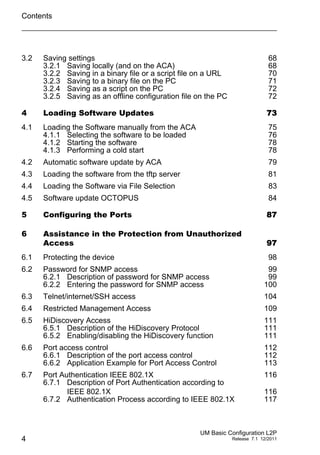
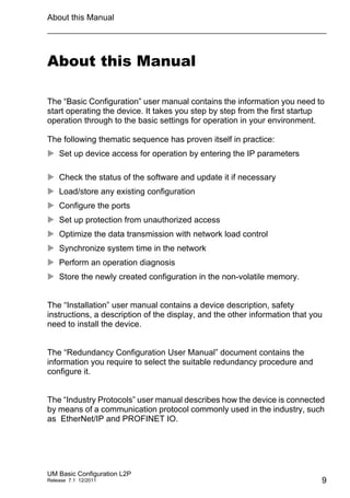
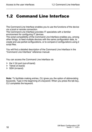
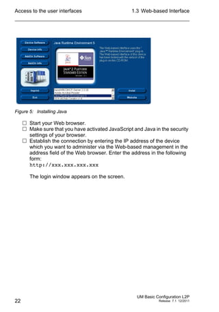
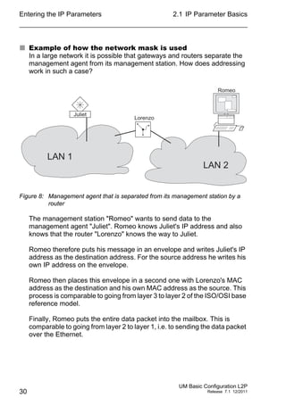
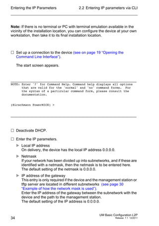
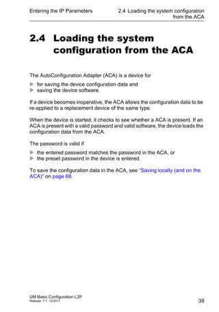
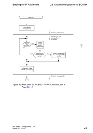
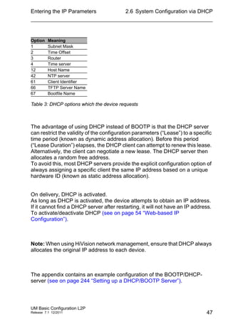
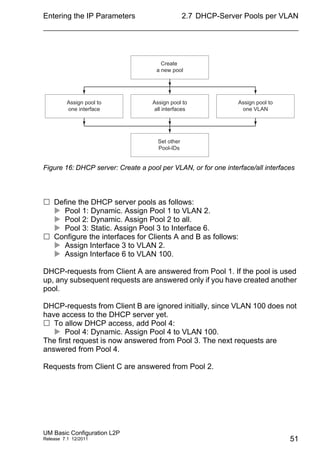
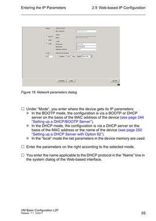
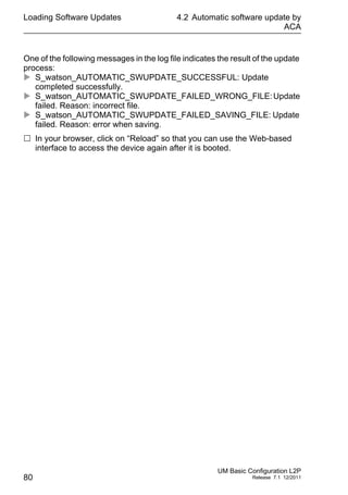
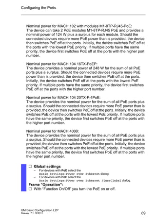
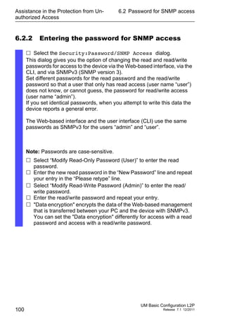
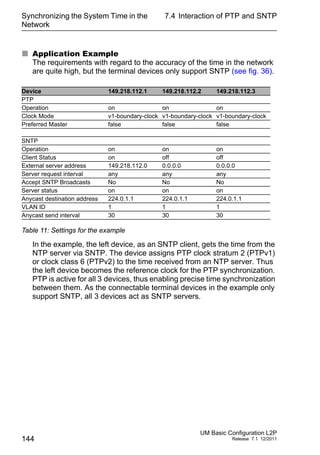
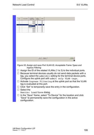
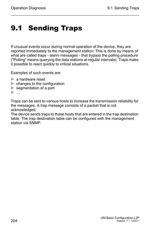
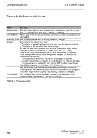
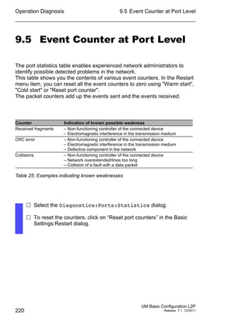
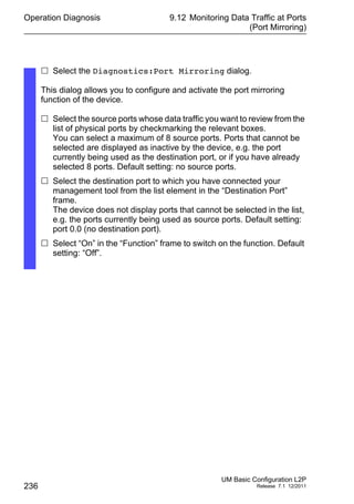
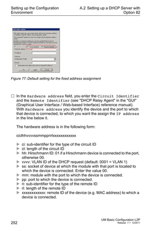
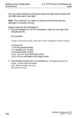
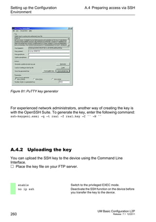
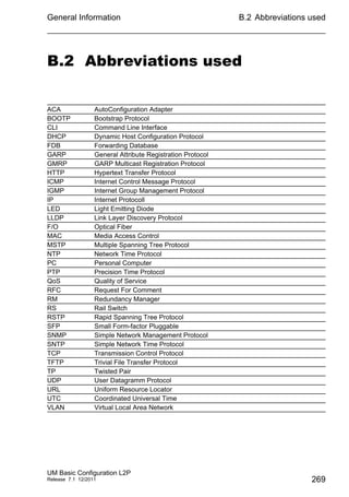
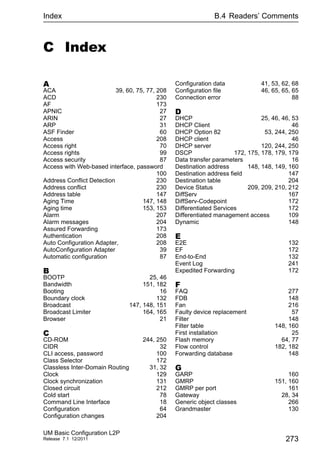
Port settings
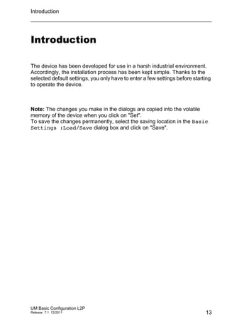
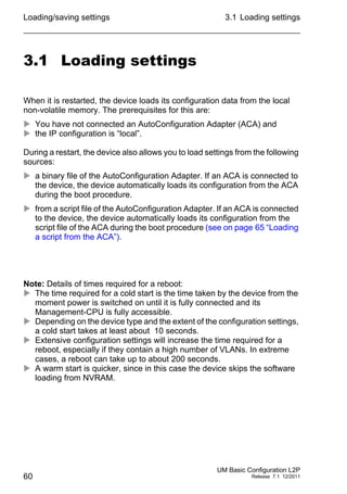
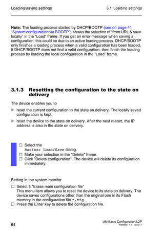
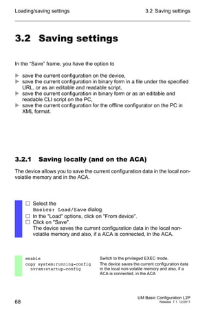
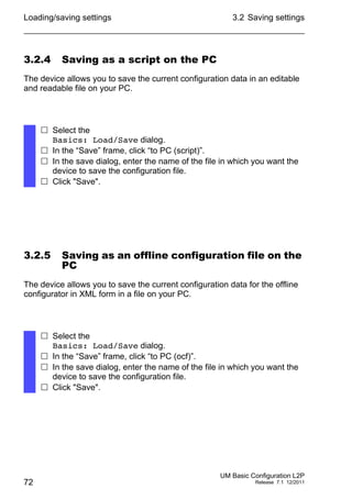
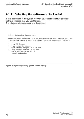
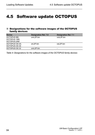
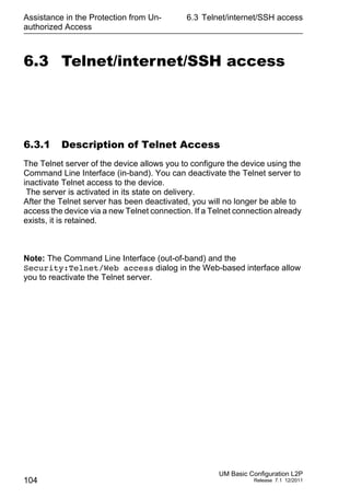
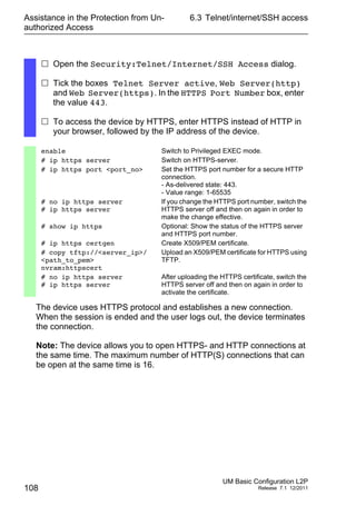
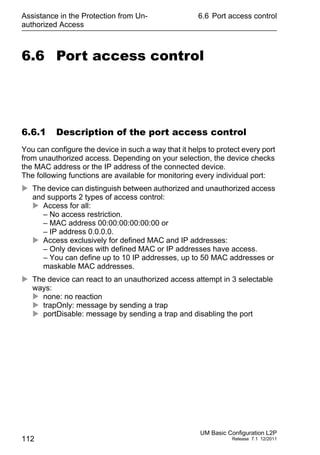
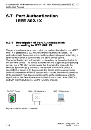
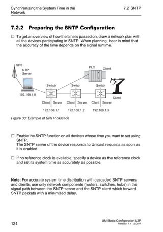
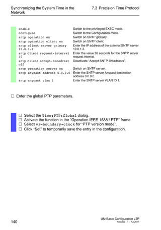
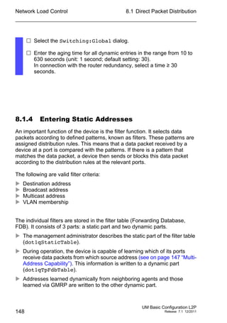
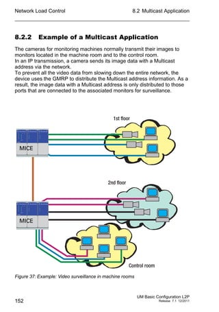
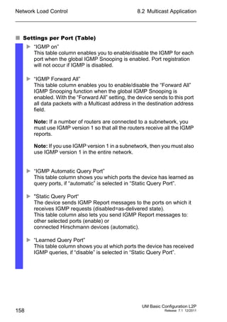
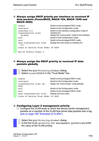
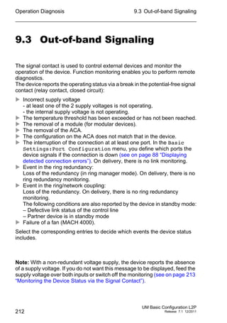
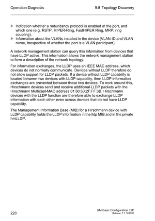
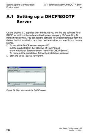
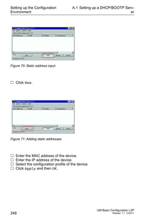
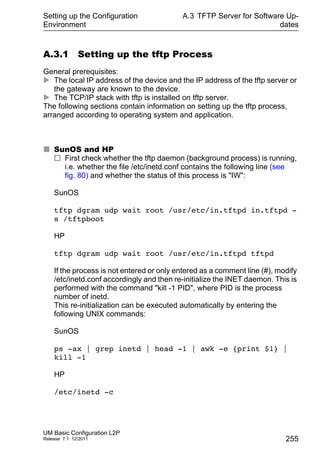
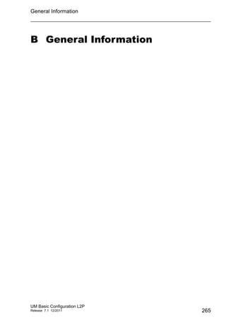
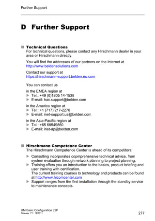
– For devices with PoE select the
Basic Settings:Power over Ethernet dialog.
– For devices with PoE+ select the
Basic Settings:Power over Ethernet Plus:Port dialog.
The table only shows ports that support PoE.
In the “POE on” column, you can enable/disable PoE at this port.
The “Status” column indicates the PoE status of the port.
In the “Priority” column (MACH 4000), set the PoE priority of the port
to “low”, “high” or “critical”.
The "Class" column indicates the class of the connected device:
Class: Maximum delivered power
0: 15.4 W = As-delivered state
1: 4.0 W
2: 7.0 W
3: 15.4 W
4: reserved, treated as Class 0
For devices MACH 102 and MACH 104:
The "Class" column indicates the class of the connected device:
Class: Maximum delivered power
0: 15.4 W = As-delivered state
1: 4.0 W
2: 7.0 W
3: 15.4 W
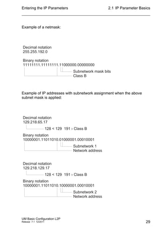
4: 30.0 W
The column „Consumption [W]“ displays the current power
delivered at the respective port.
The “Name” column indicates the name of the port, see
Basic settings:Port configuration.](https://image.slidesharecdn.com/umbasicconfigl2prel71en-140630043806-phpapp01/85/Um-basic-config_l2p_rel71_en-91-320.jpg)


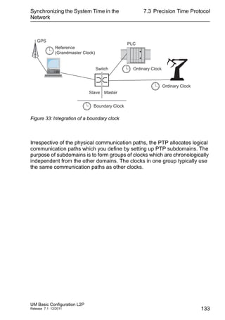
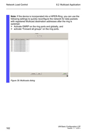
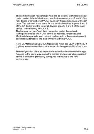
![Network Load Control
UM Basic Configuration L2P
Release 7.1 12/2011
8.2 Multicast Application
155
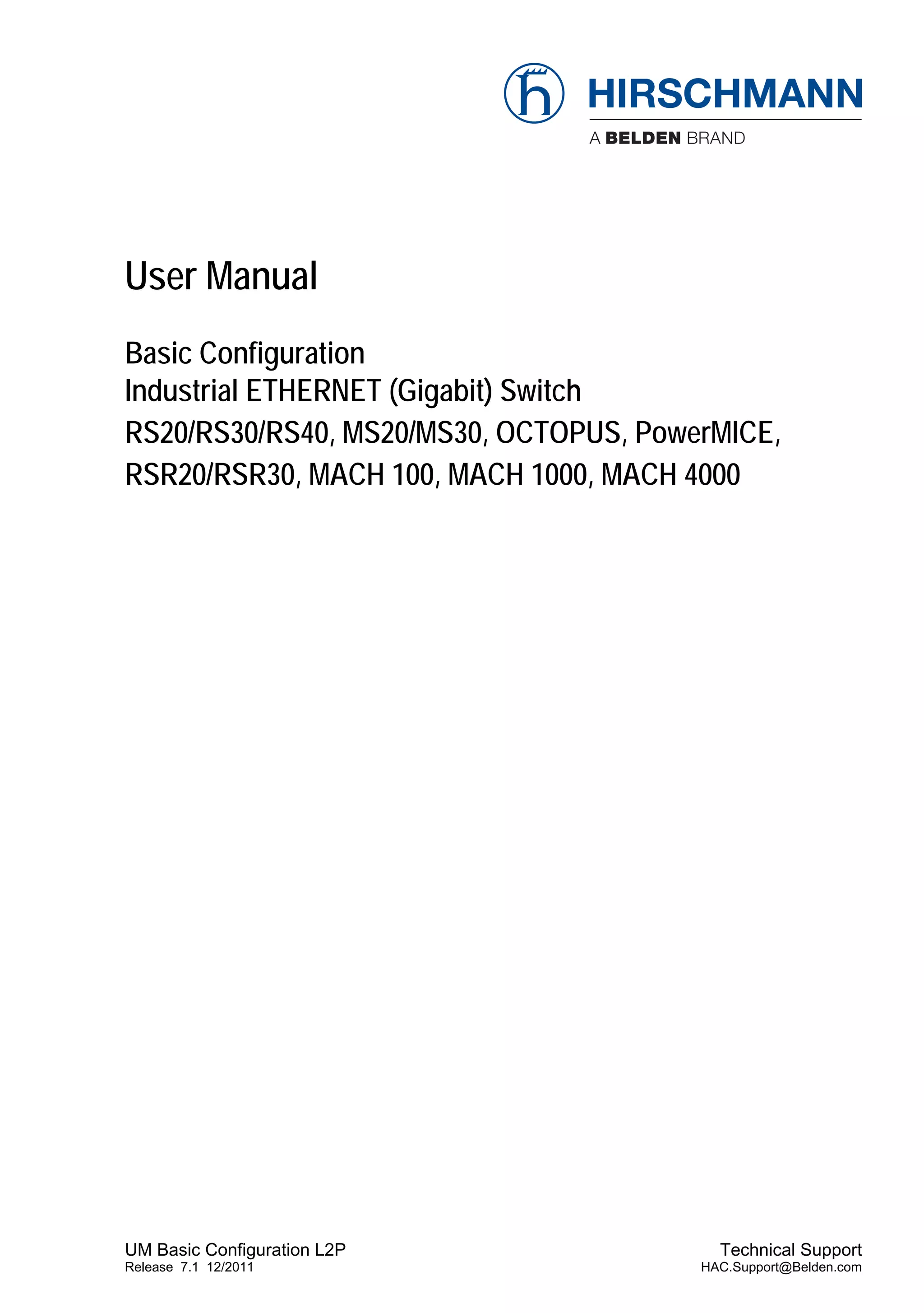
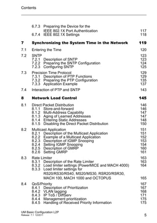
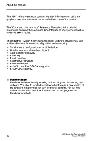
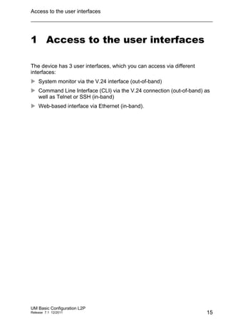
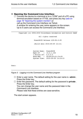
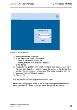
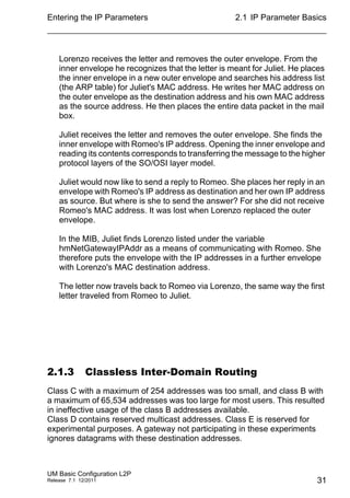
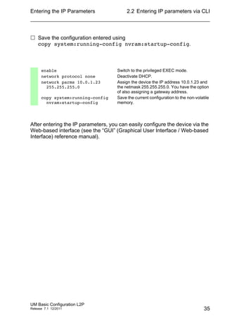
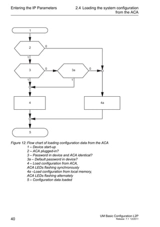
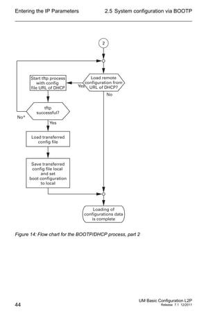
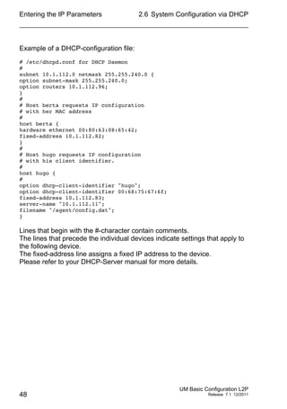
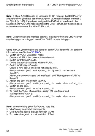
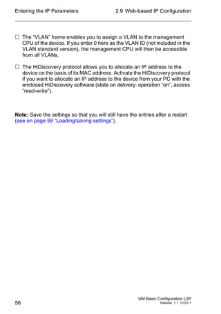
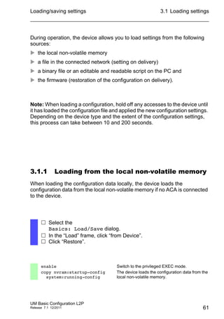
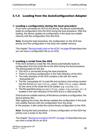
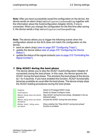
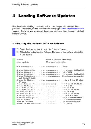
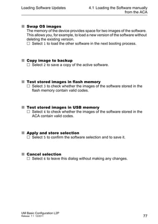
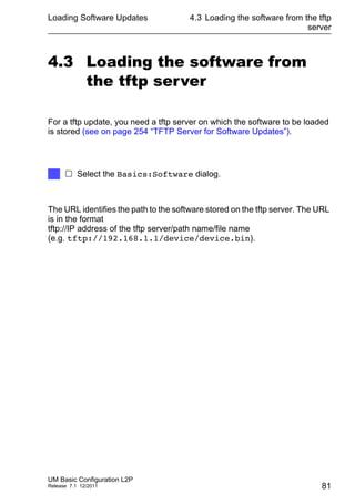
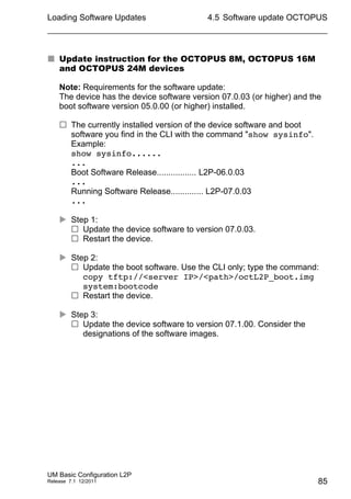
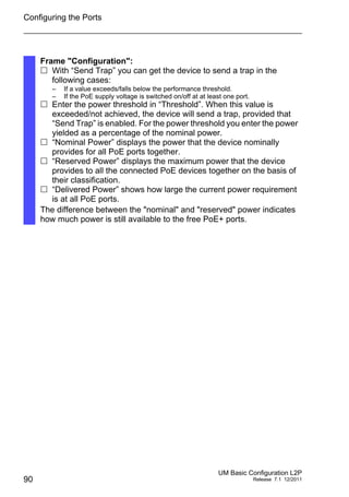
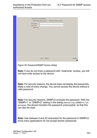
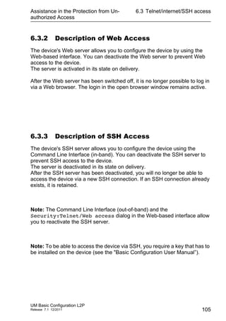
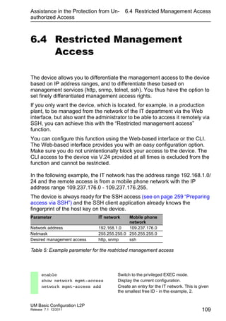
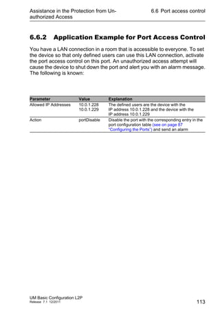
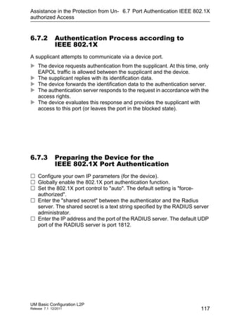
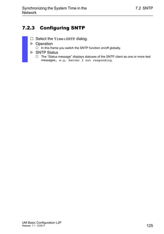
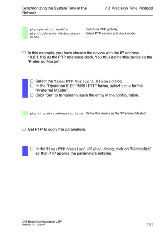
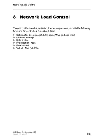
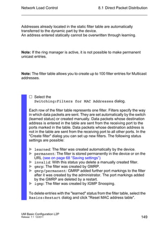
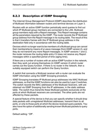
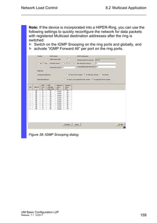
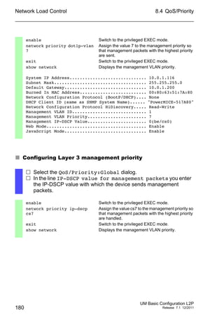
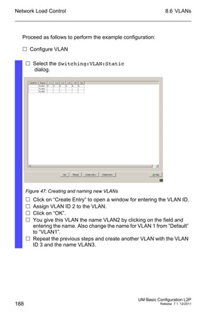
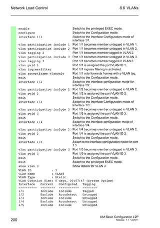
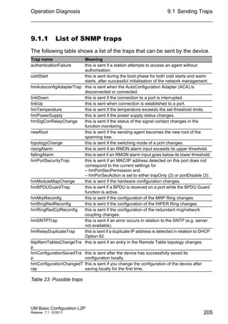
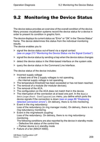
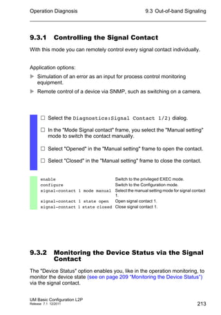
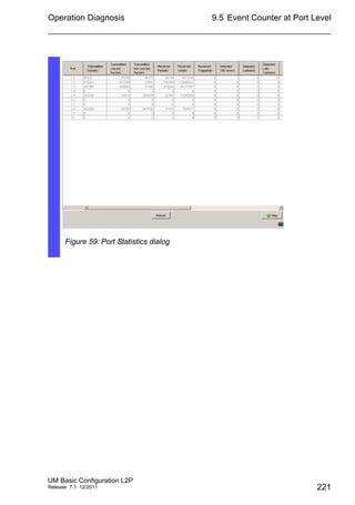
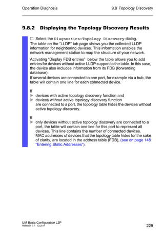
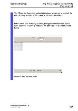
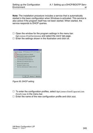
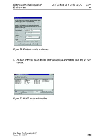
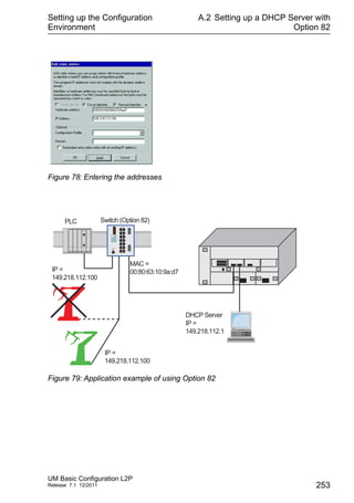
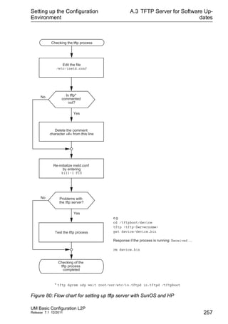
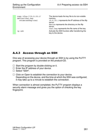
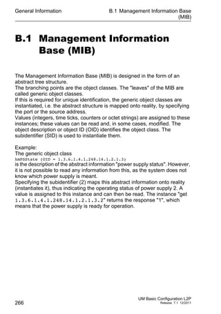
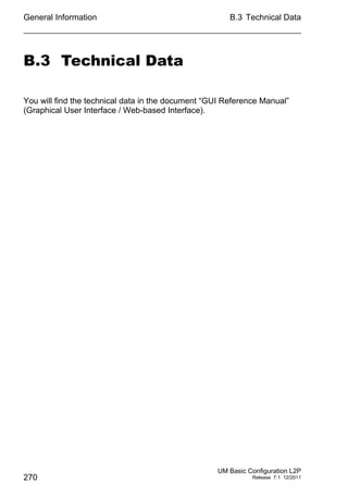
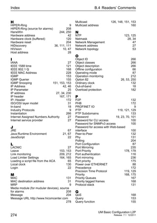
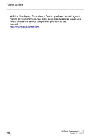
IGMP Querier
“IGMP Querier active” allows you to enable/disable the Query function.
“Protocol version” allow you to select IGMP version 1, 2 or 3.
In “Send interval [s]” you specify the interval at which the device sends
query packets (valid entries: 2-3,599 s, default setting: 125 s).
Note the connection between the parameters Max. Response Time,
Send Interval and Group Membership Interval (see on page 156
“Parameter Values”).
IGMP-capable terminal devices respond to a query with a report
message, thus generating a network load.
Select large sending intervals if you want to reduce the load on your
network and can accept the resulting longer switching times.
Select small sending intervals if you require short switching times and
can accept the resulting network load.
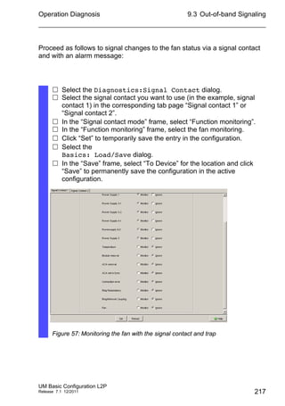
IGMP Settings
“Current querier IP address” shows you the IP address of the device
that has the query function.
In “Max. Response Time” you specify the period within which the
Multicast group members respond to a query (valid values: 1-3,598 s,
default setting: 10 s).
Note the connection between the parameters Max. Response Time,
Send Interval and Group Membership Interval (see on page 156
“Parameter Values”).
The Multicast group members select a random value within the
maximum response time for their response, to prevent all the Multicast
group members responding to the query at the same time.
Select a large value if you want to reduce the load on your network and
can accept the resulting longer switching times.
Select a small value if you require short switching times and can accept
the resulting network load.
In “Group Membership Interval” you specify the period for which a
dynamic Multicast group remains entered in the device if it does not
receive any report messages (valid values: 3-3,600 s, default setting:
260 s).
Note the connection between the parameters Max. Response Time,
Send Interval and Group Membership Interval (see on page 156
“Parameter Values”).](https://image.slidesharecdn.com/umbasicconfigl2prel71en-140630043806-phpapp01/85/Um-basic-config_l2p_rel71_en-155-320.jpg)

![Network Load Control
172
8.4 QoS/Priority
UM Basic Configuration L2P
Release 7.1 12/2011
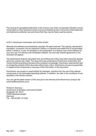
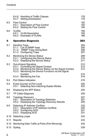
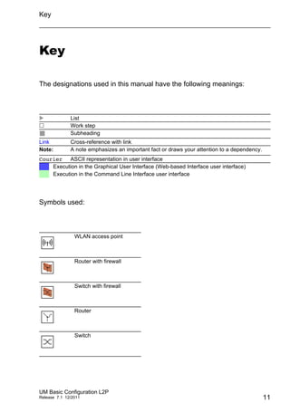
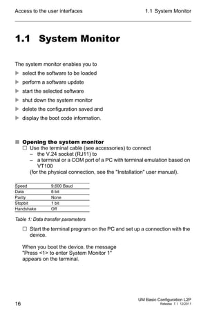
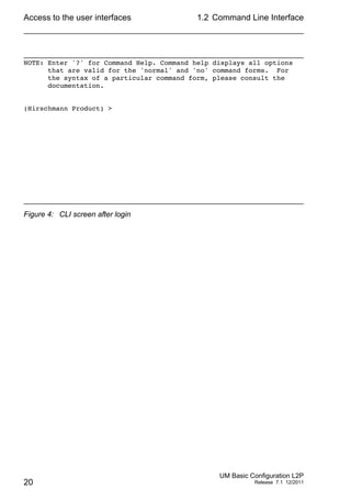
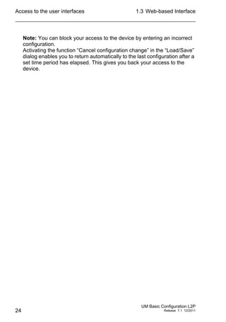
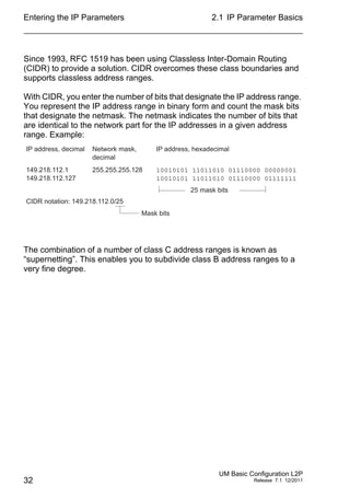
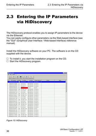
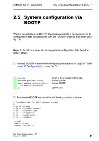
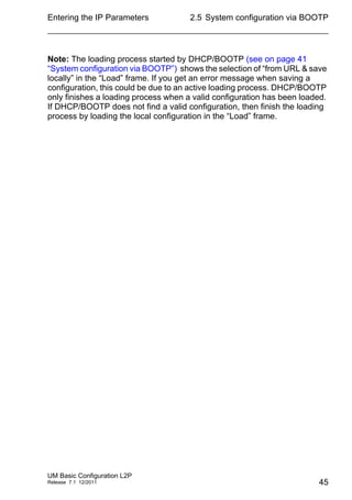
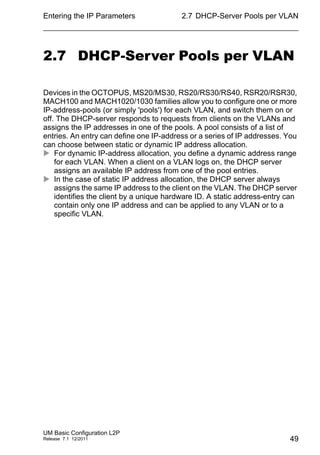
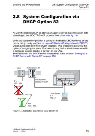
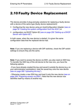
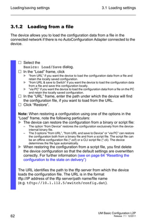
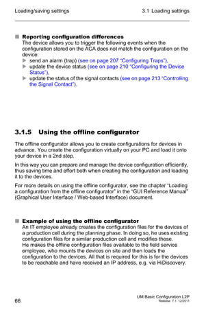
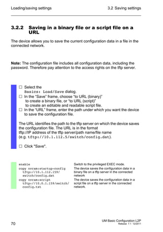
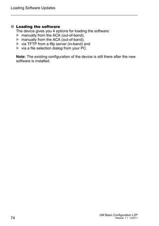
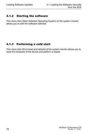
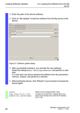
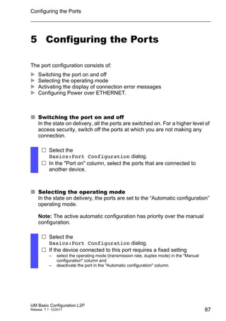
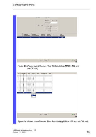
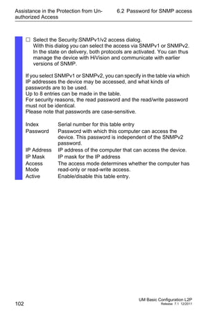
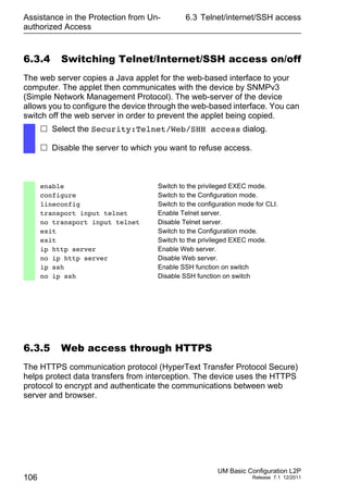
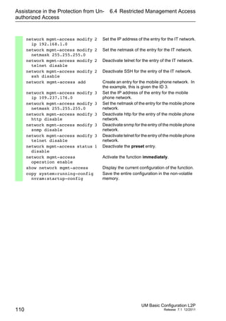
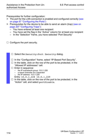
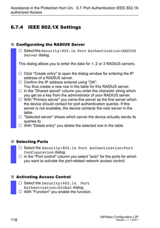
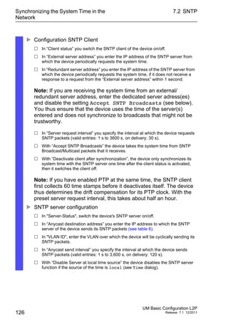
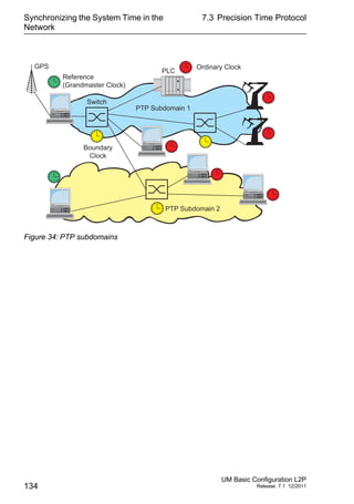
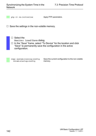
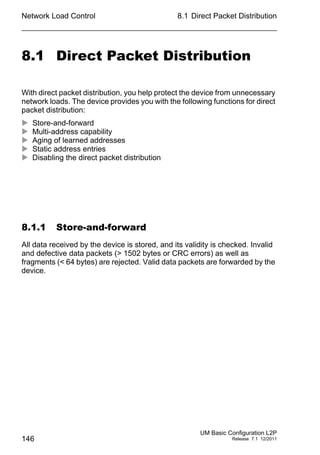
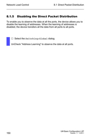
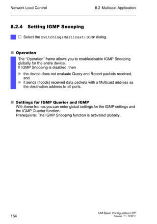
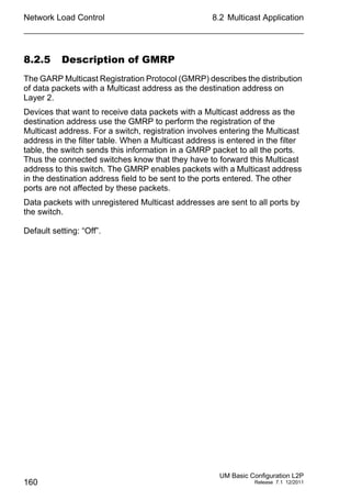
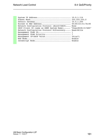
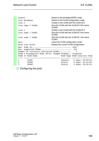
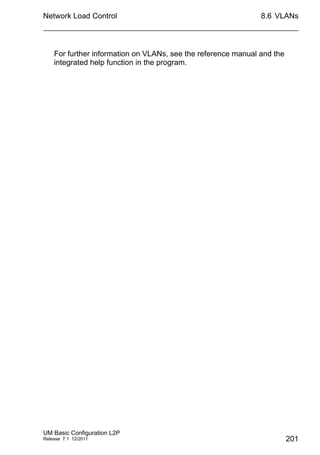
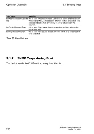
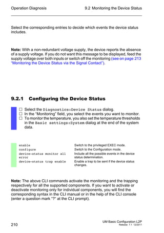
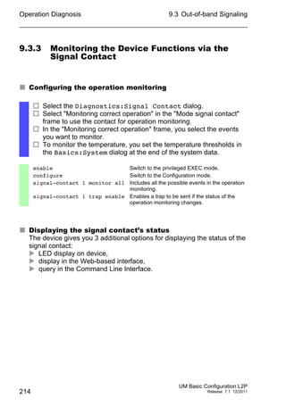
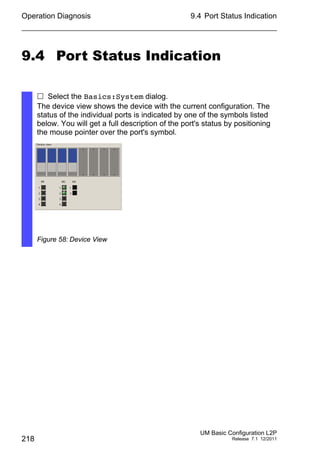
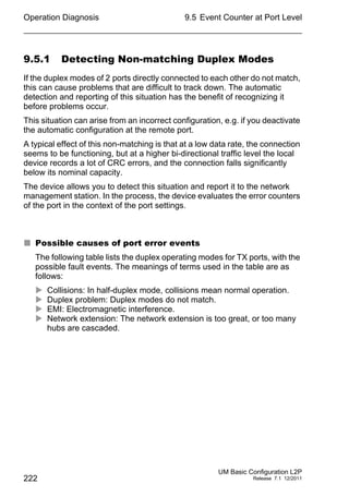
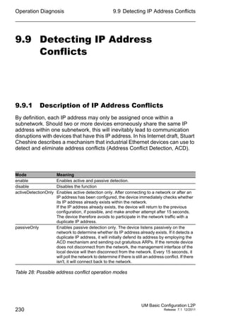
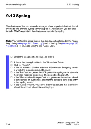
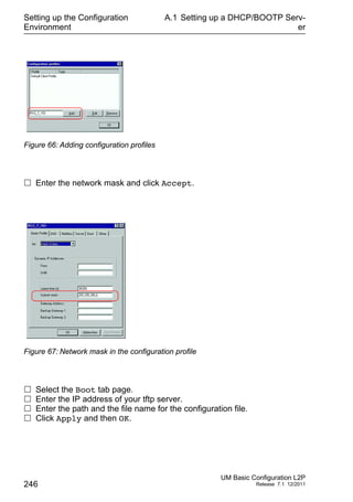
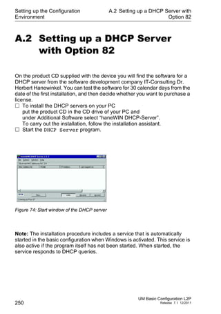
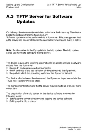
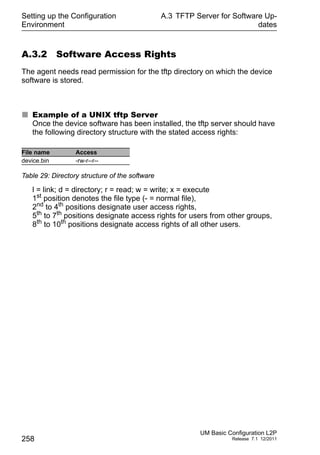
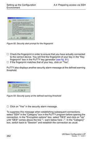
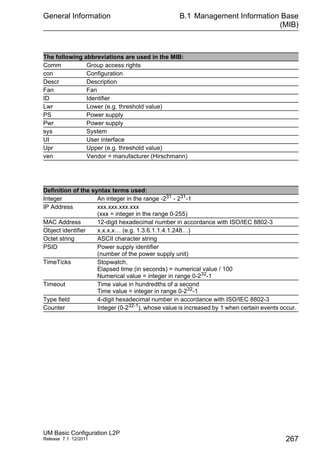
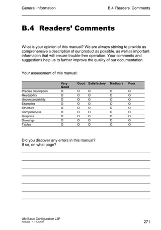
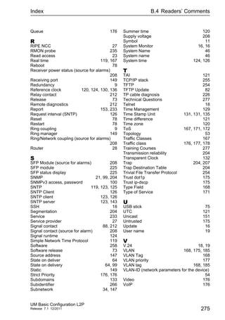
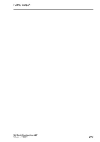
Differentiated Services
The Differentiated Services field in the IP header (see fig. 44) newly
defined in RFC 2474 - often known as the DiffServ code point or DSCP -
replaces the ToS field and is used to mark the individual packets with a
DSCP. Here the packets are divided into different quality classes. The first
3 bits of the DSCP are used to divide the packets into classes. The next
3 bits are used to further divide the classes on the basis of different
criteria. In contrast to the ToS byte, DiffServ uses 6 bits for the division
into classes. This results in up to 64 different service classes.
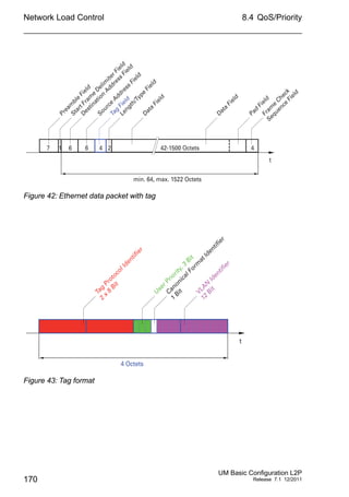
Figure 44: Differentiated Services field in the IP header
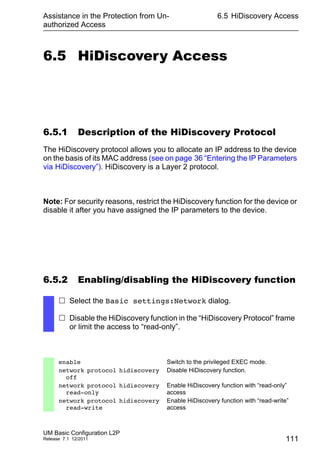
The different DSCP values get the device to employ a different forwarding
behavior, namely Per-Hop Behavior (PHB). PHB classes:
Class Selector (CS0-CS7): For reasons of compatibility to TOS/IP
Precedence
Expedited Forwarding (EF): Premium service.
Reduced delay, jitter + packet loss (RFC 2598)
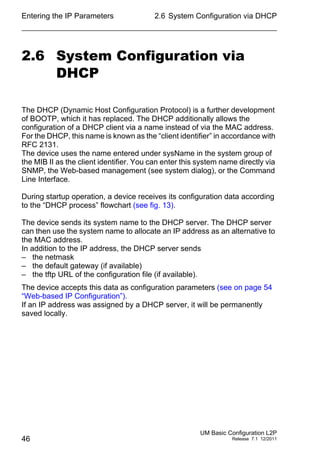
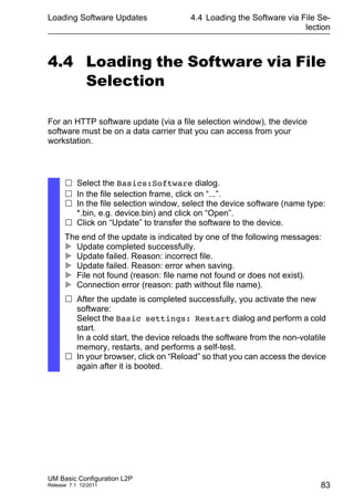
Bits (0-2): IP Precedence Defined Bits (3-6): Type of Service Defined Bit (7)
111 - Network Control 0000 - [all normal] 0 - Must be zero
110 - Internetwork Control 1000 - [minimize delay]
101 - CRITIC / ECP 0100 - [maximize throughput]
100 - Flash Override 0010 - [maximize reliability]
011 - Flash 0001 - [minimize monetary cost]
010 - Immediate
001 - Priority
000 - Routine
Table 14: ToS field in the IP header
Bits 0 1 32 4 5 6 7
Currently
Unused
(CU)
Differentiated Services Codepoint
(DSCP) RFC 2474
Class Selector
Codepoints](https://image.slidesharecdn.com/umbasicconfigl2prel71en-140630043806-phpapp01/85/Um-basic-config_l2p_rel71_en-172-320.jpg)
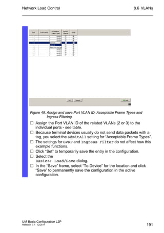


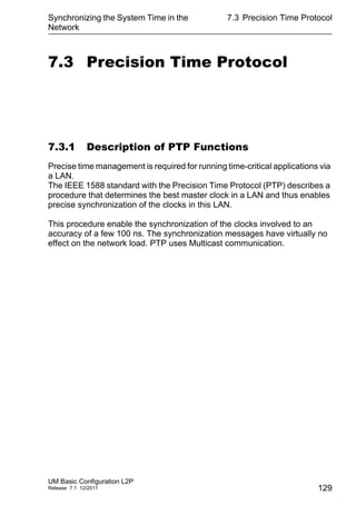
This document provides a user manual for basic configuration of Hirschmann industrial Ethernet switches. It guides the user through initial startup, IP configuration, software updates, port configuration, security settings, network optimization, system time synchronization, operation diagnosis, and saving the configuration. The manual also describes additional support documentation and software that is available to aid in configuration.