Downloaded 14 times
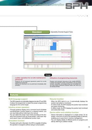
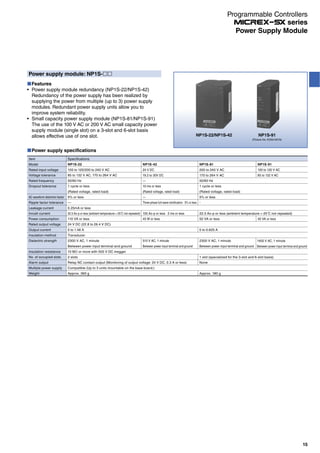
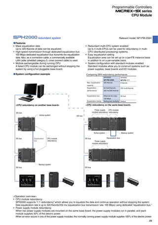
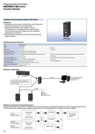
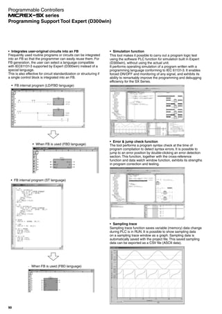
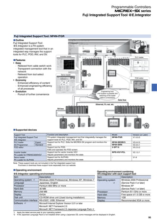
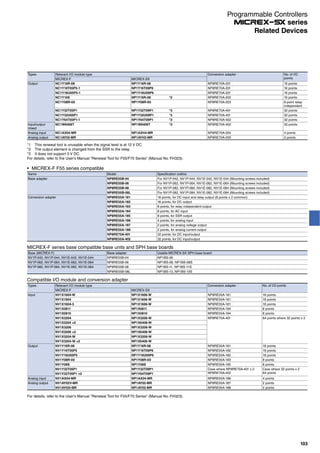
![SPH3000/SPH3000D
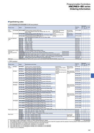
SPH3000MM
SPH3000MG
SPH2000
High speed and large
capacity/Ethernet built-in
Ethernet built-in
256K
48K 256K
48K 96K*
128K 256K
32K 74K 117K 245K
48K 256K
8K 16K
board type
Ultra-high
speed
E-SX bus
High-
speed
motion
Motion
monitoring
control
Performance
* SPH3000D only
PLC-MIX value
[Instruction/μs]
Large
capacity/
high-speed
SX-Net
Machine
built-in
customization
Sequence
control
Monitoring
control
instrumentation
information
process
Program capacity (K step)
INDEX
Overview of MICREX-SX series 2
Network configuration of SPH 4
Features of SPH 6
Integrated programmable support 10
Basic configuration of SX bus 12
MICREX-SX series SPH 14
General specifications 14
Power supply module 15
CPU module 16
Base board 28
E-SX bus product 29
Standard I/O module 32
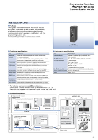
Communication Module 47
Function and positioning control module 76
Programming support tool 89
Dimensions 110
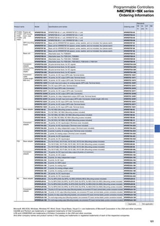
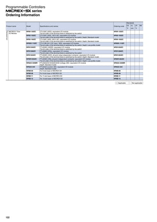
Ordering informations 117
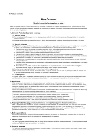
Product warranty 123
3](https://image.slidesharecdn.com/catalog-plc-fuji-190722092557/85/Catalog-PLC-Fuji-Electric-3-320.jpg)
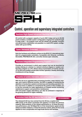
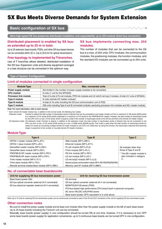
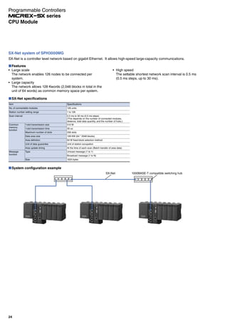
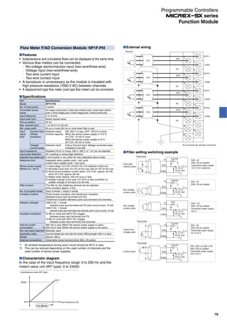
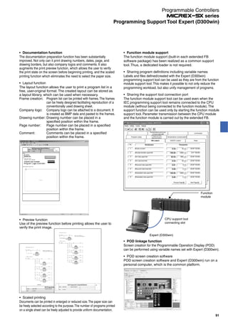
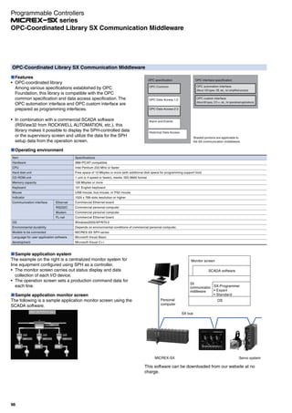
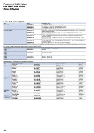
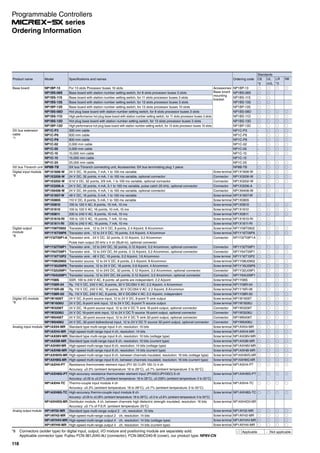
![Ultra-high speed E-SX bus
Comparison of functions and performances between the E-SX bus and the SX bus
Direct connection I/O capacity Transmission speed
SX bus
E-SX bus
512word 25Mbps
Refresh performance Tact accuracy
128W/ms 100μs
±1μs or less
Distance
[Between stations] [Total distance]
25m 25m
SX bus
E-SX bus
SX bus
E-SX bus
SX bus
E-SX bus
SX bus
E-SX bus
SX bus
E-SX bus
16times
4times
∼
∼
4096 word 100 Mbps
2048 W/ms
100 m 1 km
Over 100times
40times
4times8times
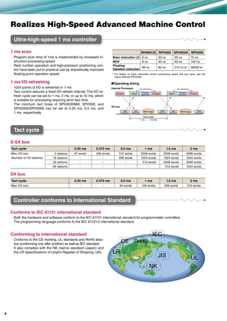
Function and performance SPH3000 (D) SPH3000MM/MG
System bus SX bus SX bus E-SX bus
Direct connection I/O capacity 512 words 512 words 4096 words
Refresh performance 128 words/ms 128 words/ms 2048 words/ms
Transmission speed 25 Mbps 25 Mbps 100 Mbps
Tact fluctuation 100 μs 100 μs ± 1μs or less
Synchronization between stations None None Provided (±1 µs or less)
Distance (between stations/total distance) 25 m/25 m 25 m/25 m 100 m/1 km
Continued operation with the line broken
(Loopback)
None None Provided
8](https://image.slidesharecdn.com/catalog-plc-fuji-190722092557/85/Catalog-PLC-Fuji-Electric-8-320.jpg)
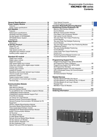
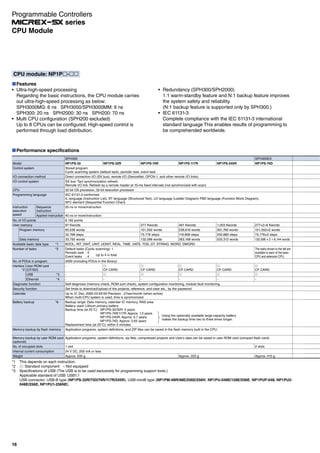
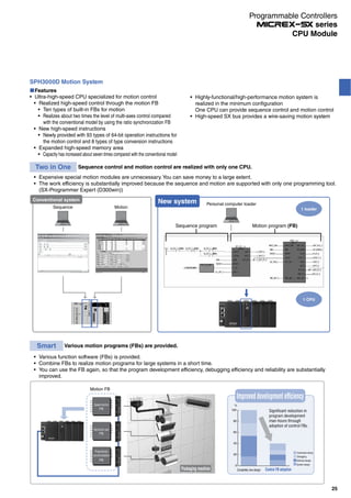
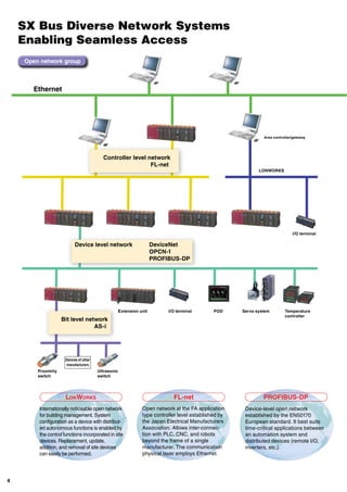
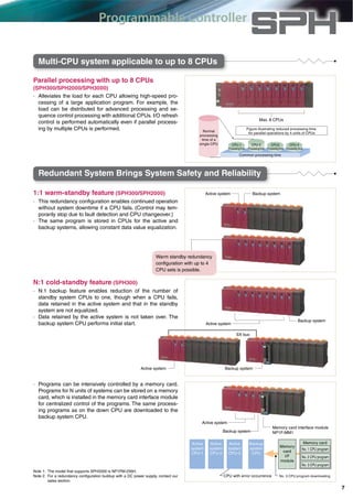
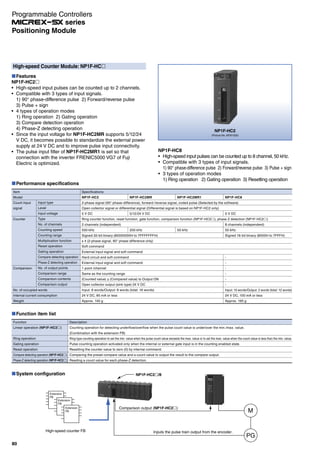
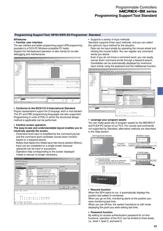
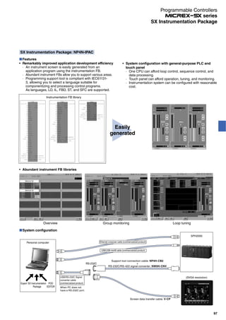
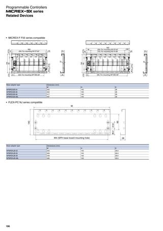
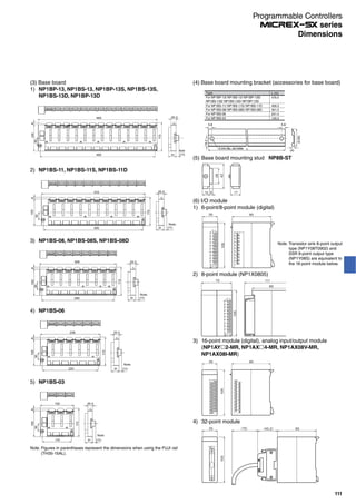
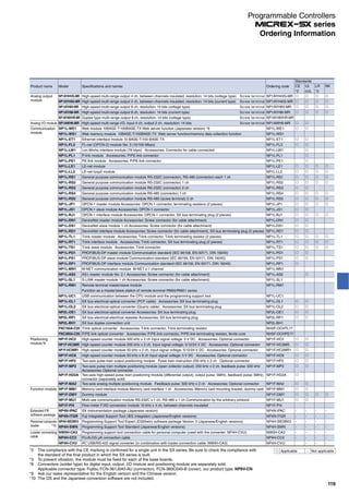
![Base board: NP1B -
Name
Standard base board
High-performance base board
Standard base board with
station number setting switch
High-performance base board
with station number setting switch
Standard hot plug base board
with station number setting switch
Station number setting switch incorporated
high-performance hot plug base board
Base board 3 slots
Base board 6 slots
Base board 8 slots
Base board 11 slots
Base board 13 slots
Base board 13 slots
Base board 8 slots
Base board 11 slots
Base board 13 slots
Base board 13 slots
Base board 8 slots
Base board 11 slots
Base board 13 slots
Base board 13 slots
Model
NP1BS-03
NP1BS-06
NP1BS-08
NP1BS-11
NP1BS-13
NP1BP-13
NP1BS-08S
NP1BS-11S
NP1BS-13S
NP1BP-13S
NP1BS-08D
NP1BS-11D
NP1BS-13D
NP1BP-13D
Max. no. of modules
2 (Not include a power supply)
5 (Not include a power supply)
6 (Not include a power supply)
9 (Not include a power supply)
11 (Not include a power supply)
11 (Not include a power supply)
6 (Not include a power supply)
9 (Not include a power supply)
11 (Not include a power supply)
11 (Not include a power supply)
6 (Not include a power supply)
9 (Not include a power supply)
11 (Not include a power supply)
11 (Not include a power supply)
Remarks
SX bus 3 slots, processor bus 2 slots
SX bus 6 slots, processor bus 4 slots
SX bus 8 slots, processor bus 3 slots
SX bus 11 slots, processor bus 3 slots
SX bus 13 slots, processor bus 3 slots
SX bus 13 slots, processor bus 10 slots
SX bus 8 slots, processor bus 3 slots
SX bus 11 slots, processor bus 3 slots
SX bus 13 slots, processor bus 3 slots
SX bus 13 slots, processor bus 10 slots
SX bus 8 slots, processor bus 3 slots
SX bus 11 slots, processor bus 3 slots
SX bus 13 slots, processor bus 3 slots
SX bus 13 slots, processor bus 10 slots
Internal current consumption
35 mA or less
45 mA or less
50 mA or less
60 mA or less
70 mA or less
70 mA or less
60 mA or less
70 mA or less
80 mA or less
80 mA or less
70 mA or less
80 mA or less
80 mA or less
80 mA or less
Weight
Approx. 250 g
Approx. 420 g
Approx. 540 g
Approx. 720 g
Approx. 840 g
Approx. 840 g
Approx. 550 g
Approx. 730 g
Approx. 850 g
Approx. 850 g
Approx. 550 g
Approx. 730 g
Approx. 850 g
Approx. 850 g
Note: Mount a power supply module, plus not less than one module, onto the base board.
Make sure to always mount the power supply module at the left side of the base board.
A high-performance base board is used when configuring the system, such as one with multi-CPUs and redundancy, and it uses a processor bus heavily.
Modules which use the processor bus are as follows:
· CPU module · FL-net module
· P-link/PE-link module · LE-net related module
Dimension
*
* Station number setting switch
Incorporated in base board with the station number setting switch
W2
W1
108
501
8.13
8
[Units: mm]
Note: When the connector is mounted, the depth is a max. of
195.3mm.
The bracket is already mounted on the base board.
No. of slots
3
6
8
11
13
W1
133 mm
238 mm
308 mm
413 mm
483 mm
W2
115 mm
220 mm
290 mm
395 mm
465 mm
28
Base Board
Programmable Controllers
series](https://image.slidesharecdn.com/catalog-plc-fuji-190722092557/85/Catalog-PLC-Fuji-Electric-28-320.jpg)
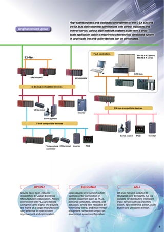
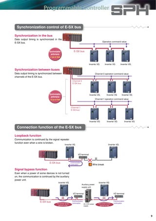
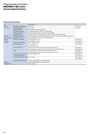
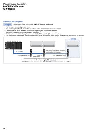
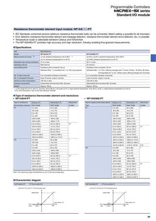
![Digital input/output unit
It is a separate mounting type I/O unit that can be directly connected to the E-SX bus.
Internal circuit
COM
Fuse blowout
Detection circuit Internal circuit
Voltage
stabilizing
circuit
Fuse
COM- COM+
L
0V+24V 0.0 0.2 0.4 0.6 NC 0.8 0.10 0.12 0.14 NC
FG NC 0.1 0.3 0.5 0.7 C0 0.9 0.11 0.13 0.15 C1
1.0 1.2 1.4 1.6 NC 1.8 1.10 1.12 1.14 NC
1.1 1.3 1.5 1.7 C2 1.9 1.11 1.13 1.15 C3
FG NC 0.1 0.3 0.5 0.7 C0- 0.9 0.11 0.13 0.15 C1- 1.1 1.3 1.5 1.7 C2- 1.9 1.11 1.13 1.15 C3-
L L L L L L L L L L L L L L L L L L L L L L L L L L L L L L L L
0V+24V 0.0 0.2 0.4 0.6 C0+ 0.8 0.10 0.12 0.14 C1+ 1.0 1.2 1.4 1.6 C2+ 1.8 1.10 1.12 1.14 C3+
Internal circuit diagram of digital inputExample external connection of digital input
Internal circuit diagram of digital output
Example external connection of digital output
Digital input unit
Item Specifications
Model NU2X3206-W
Input method Sink/source in common use 32-point (8-point common x 4 circuits)
Input voltage Rating: 24 V DC, max. acceptable: 30 V DC, Acceptable ripple rate: 5% or less
Power supply method E-SX bus cable (24 V DC)
Rated current 7 mA (at 24 V DC)
Standard operation
range
OFF ON: 15-30 V
ON OFF: 0-5 V
Input delay time OFF to ON: 25 µs or less (hard filter time) + (soft filter time)
ON to OFF: 75 µs or less (hard filter time) + (soft filter time)
Insulation method Photocoupler insulation
External connections Detachable M3 screw terminal block
Internal current consumption Operating: 260 mA or less, Bypassing: 93 mA
Dimension
(W×H×D) [mm]
240 x 65 x 60 (except DIN rail mounting protrusions)
Weight Approx. 430 g
Digital output unit
Item Specifications
Model NU2Y32T09P6
Output method Transistor sink 32 points (8-point common x 4 circuits)
Output voltage Rating: 24 V DC, Allowable: 10.8 V to 30 V DC
Power supply method E-SX bus cable (24 V DC)
Max. load current 0.6 A/ point 4 A/ common
Output delay time OFF to ON: 10 µs or less
ON to OFF: 200 µs or less
Output protection Overload protection: built-in fuse (common unit 4 fuses)
Surge suppression: Varistor (total 32 points)
Insulation method Photocoupler insulation
External connections Detachable M3 screw terminal block
Internal current consumption Operating: 300 mA or less, Bypassing: 93 mA
Dimension
(W×H×D) [mm]
240 x 65 x 60 (except DIN rail mounting protrusions)
Weight Approx. 410 g
[Units: mm]240
60
55
65
230
55
(70)
(69)
Outline dimensional drawing
(digital I/O unit, high-speed counter unit)
E-SX bus product
Digital input unit Analog input unit High-speed counter Integrated type
interface module
Auxiliary power
supply unit
29
E-SX Bus Product
Programmable Controllers
series](https://image.slidesharecdn.com/catalog-plc-fuji-190722092557/85/Catalog-PLC-Fuji-Electric-29-320.jpg)
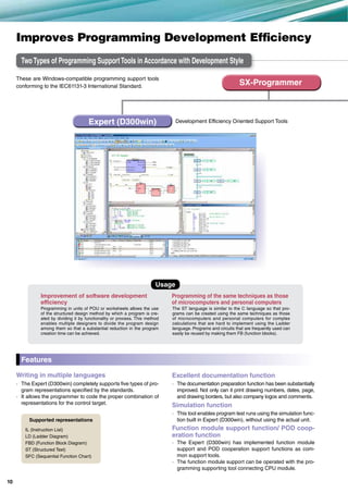
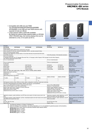
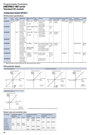
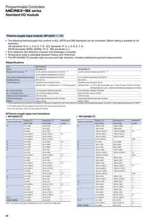
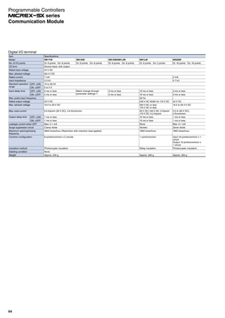
![Analog input/output unit
It is a separate mounting type analog unit that can be directly
connected to the E-SX bus.
Analog input unit
Item Specifications
Model NU2AXH2-MR
Input format Multi-range 2 channels
Power supply method E-SX bus cable (24 V DC)
Signal range 0 to 10V -5 to +5V -20 to +20mA 0 to 20mA
0 to 5V -10 to +10V 4 to 20mA
1 to 5V
Digital converted value
(INT type)
0 to 20000 -20000 to +20000 0 to 20000
Resolution 15 bits
Measurement accuracy ±0.1% of F.S.R. (Ta = 23˚C ±5˚C), setting moving average for 8 data or more
Converting speed 25 μs/2 channels
Insulation method Between analog input terminal and FG: Photocoupler and transformer insulated
Between analog input terminal and channel: Transformer insulated
External connections Detachable M3 screw terminal block
Internal current consumption Operating: 300 mA or less, Bypassing: 93 mA
Dimension
(W×H×D) [mm]
165 x 65 x 60 (except DIN rail mounting protrusions)
Weight Approx. 360 g
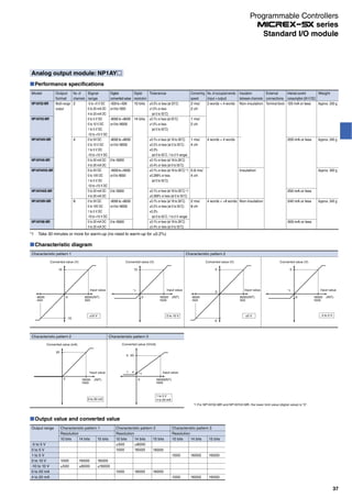
Analog output unit
Item Specifications
Model NU2AYH2V-MR
Output format Voltage multi-range 2 channels
Power supply method E-SX bus cable (24 V DC)
Signal range -10 to +10 V -5 to +5 V 0 to 10 V 0 to 5 V 1 to 5 V
Digital converted value
(INT type)
-20000 to +20000 0 to 20000
Max. resolution 0.5 mV 0.25 mV 0.5 mV 0.25mV 0.2mV
Measurement accuracy ±0.1% of F.S.R. (Ta = 23°C±5°C)
Converting speed 25 μs/2 channels
Insulation method Between analog output terminal and FG: Photocoupler and
transformer insulated
Between analog output terminal and channel: Transformer insulated
External connections Detachable M3 screw terminal block
Internal current consumption Operating: 300 mA or less, Bypassing: 93 mA
Dimension
(W×H×D) [mm]
165 x 65 x 60 (except DIN rail mounting protrusions)
Weight Approx. 350 g
D/A conversion circuit
Analog output power
insulation circuit
V1- V1+ V2- V2+
Internal circuit
Internal power
supply insulation
circuit
Internal circuit diagram of analog output
+24V 0V N.C
N.CN.C
V1+
V1
N.C N.C N.C
N.C N.C N.C
N.C N.C N.C N.C
N.CN.CN.CN.C
V2+
FG V2
+
Analog
input devices
Analog
input devices
Shielded
twisted pair cable
Example external connection of analog input
Analog output unit characteristic diagram
-10
10
Converted value (V)
Output value
(INT type)
-10 to 10V
20000
-20000
+
*Example wiring of
voltage input
*Example wiring of
current input
+24 V 0V N.C. V1+ I1+ N.C. N.C. V2+ I2+ N.C. N.C. N.C.
FG N.C. N.C. C2 N.C. N.C. N.C. C2 N.C. N.C. N.C. N.C
Shielded
twisted pair cable
Analog
output devices
Analog
output devices
Example external connection of analog input
Internal circuit diagram of analog input
Internal circuit
Internal power
supply insulation
circuit
Analog input power
insulation circuit
A/D conversion circuit
C1- V1+ L1+ C2- V2+ I2+
[Units: mm]
(69)
55
2xM
4
155
65∅
4.555
155
165
4.5
6.5
60
Outline dimensional drawing (analog I/O units)
Analog input unit characteristic diagram
-20000
-10 to 10 V
Input value (V)
Converted value (INT type)
20000
Input value (V)
10
-10
Input value (V)Input value (mA)
Converted value (INT type)
20000
20
Input value (mA)
-20
-20000
-20 to 20 mA
30
E-SX Bus Product
Programmable Controllers
series](https://image.slidesharecdn.com/catalog-plc-fuji-190722092557/85/Catalog-PLC-Fuji-Electric-30-320.jpg)
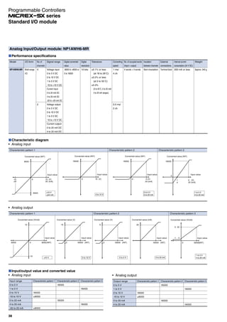
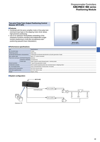
![Item Specifications
Model NU2F-HC2
Input format 90-degree phase difference, 2-phase signal, 2-channel
Power supply method E-SX bus cable (24 V DC)
Signal type Differential input Open collector Open collector Open collector
Rated voltage 5 V DC 5 V DC 12 V DC 24 V DC
Response frequency 1MHz 250KHz
Max. input frequency 4 Mbps 1 Mbps
Counting range Signed 32-bit binary (-2147483648 to +2147483647)
Counting operation
mode
Linear/ring operation, gate operation, preset operation latch operation,
Z phase detection operation
Insulation method Photocoupler insulation
External connections Detachable M3 screw terminal block
Internal current
consumption
Operating: 250 mA or less, Bypassing: 93mA or less
Dimension
(W×H×D) [mm]
240 x 65 x 60 (except DIN rail mounting protrusions)
Weight Approx. 500 g
High-speed counter unit
Item Specifications
Model NP1L-RU1
No. of connectable modules Max. 8 units/configuration
SX bus control SX bus system control of self-administration station
SX bus tact period 1, 1.5, 2, 3, 4, 5 (default)
6, 7, 8, 9, 10 ms
Extension SX bus Max. 512 words (I/O extension disallowed)
SX bus controllable module Direct connection I/O module, POD, inverter, servo
(CPU module, communication module and remote I/O module not allowed)
Date exchange I/O data and messages between the higher-level E-SX bus and the lower-level SX bus
Fail-soft-RAS RAS degeneracy administration of the SX bus system of the self-
administration station
Notification to the high-level E-SX bus
USB loader connection Connection of the program support tool
Module-connectable base
board
Standard and high-performance base board: NP1B□-□□
Base board with the station number setting function: NP1B□-□□S
(Base with the live wire removal function: NP1B□-□□D not allowed)
Internal current consumption 140 mA or less
Weight Approx. 220 g
It can be mounted on the conventional SPH base board so
that the SX bus connection device which is controlled by this
module can be used as a module on the E-SX bus.
Integrated type interface module
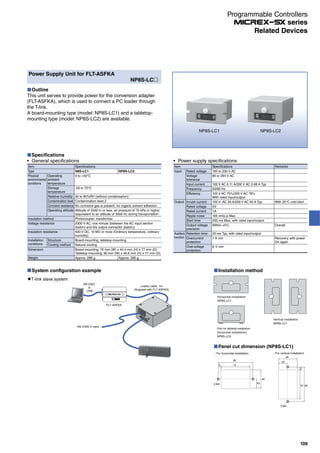
Auxiliary power supply unit
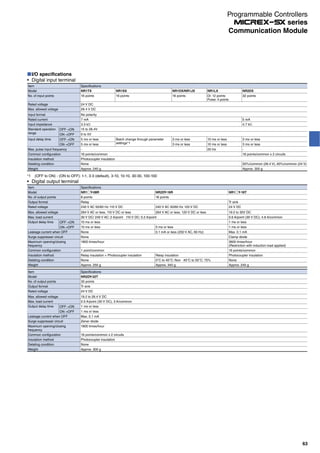
Item Specifications
Model NU2V-PA1
No. of connectable
modules
Max. of 10 units on the E-SX bus (Max. of 8 m between main units)
This one unit for 5 E-SX bus devices as a guide
Rated input voltage 24 V DC (external power supply is used)*1
Voltage tolerance 22.8 V DC to 27 V DC
Overcurrent detection When an overcurrent is detected, the 24 V DC supply is stopped.
To restart the power supply, press the reset switch.
Internal current
consumption
No load: 70 mA or less, 10 units connected: 1 A or less
Dimensions (W x H x D)
in mm
50 × 95 × 95
Weight Approx. 150 g
*1 Use a switching power supply (UL-specified product) of 24 V DC and 1.1 A for
an external power supply.
It is a separate mounting auxiliary unit to supply 24 V DC to the E-SX bus cable and to connect 5 or more units which are
compatible with the E-SX bus to the E-SX bus connector of the CPU module.
5 V DC/12 V DC/24 V DC
CH1:TB1-14/TB1-16/TB1-18
Phase A
Phase Z
Phase B
CH1:TB1-22
CH2:TB2-18
CH1:TB1-20
CH2:TB2-16
CH1:TB1-24
CH2:TB2-20
5 V DC/12 V DC/24 V DC
FGFG
Main unit
Encoder
Shielded twisted pair cable
Shielded twisted pair cable
Main unitEncoder
Phase A
Phase Z
Phase B
FG
CH1: TB1-13
CH2: TB2-9
CH1: TB1-15
CH2: TB2-11
CH1: TB1-17
CH2: TB2-13
CH1: TB1-19
CH2: TB2-15
CH1: TB1-21
CH2: TB2-17
CH1: TB1-23
CH2: TB2-19
FG
It is a separate mounting type high-speed counter that can be
directly connected to the E-SX bus.
Outline drawing of auxiliary power unit
[Units: mm]
85
40
106
(M4 screw fixing)
29.8
[101] 95
[42.4]
Differential input section wiring
Open collector input section wiring
31
E-SX Bus Product
Programmable Controllers
series](https://image.slidesharecdn.com/catalog-plc-fuji-190722092557/85/Catalog-PLC-Fuji-Electric-31-320.jpg)
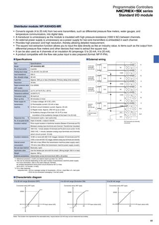

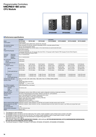
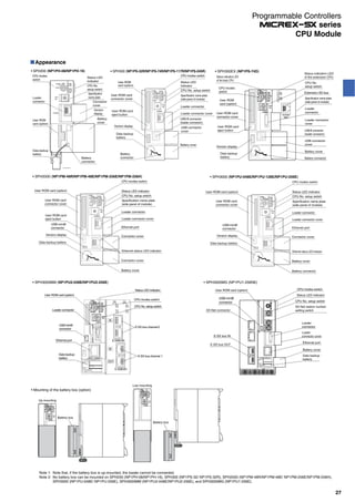
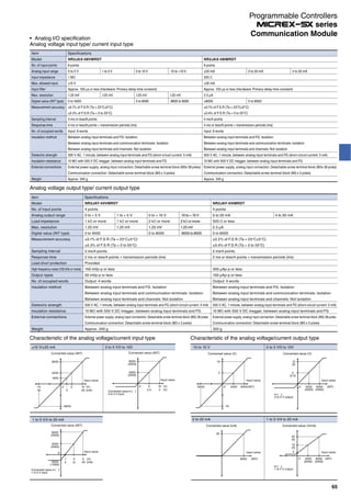
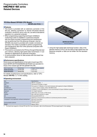
![I/O connection of connector-type modules
The following types of modules are connected using connectors and recommended for the I/O connection use.
Cable wiring diagram
[Multi-core cable with connector]
A B A B
AUX011-40 type (Fujitsu product)
[Flat cable with connector]
A B A B
1
2
1
2
1
2
1
2
AUX021-40 type (Fujitsu product)
Recommended connectors
Types
Soldered type*1
Crimp type
Wire wrapping type
Insulation displacement type
Model (Fujitsu Component Ltd.)
Jack
FCN-361J040-AU
FCN-363J040 (Housing)
FCN-363J-AU (Contact)
FCN-362J040-AU
FCN-367J040-AU/FW
Cover
FCN-360C040-B (B type)
FCN-360C040-D (D type: Wide mouthed type)
FCN-360C040-E (E type: Long screw type)
FCN-360C040-J2 (J2 type: Thinly, obliquely type)
The cover is not necessary.
*1 Fuji Electric solder type connector (NP8V-CN) is prepared (cover attached: FCN-360C040-B).
Note: For more details, refer to each manual.
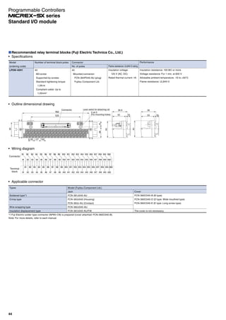
Recommended relay terminal blocks (Fuji Electric Technica Co., Ltd.)
Type/model/ordering code
· Main unit
Model
AU-CW41B1-11
Number of
terminal
block poles
41
Number of
connector
poles
40
Rating
(Connector)
Insulation voltage:
60 V (AC, DC)
Thermal current:
1 A (at 40°C)
Ordering
code
LP1W-41BA5
Performance
Insulation resistance:
100 MΩ or more
Voltage resistance:
500 V, 1 minute
Allowable ambient temperature:
-5 to +40°C
Allowable ambient humidity:
45 to 85%RH
Flame resistance:
UL94-V1
Outline dimensional drawing (AU-CW41B1-11 type)
212
202
192
4.5
44
6
653
33
9.415.6
Connector
M3.5
Wiring diagram
8
8.89 16.5
Cover
7.112 8.89
44.7
35
8.6
20.5 11.2
33.5 13.5
20
AU-CW41B1-11 type
connector installation
direction (view from
the engagement surface)
20
A1
B1
Terminal arrangement
Connector No. /Terminal block No.
21 22 23 24 25 26 27 28 29 30 31 32 33 34 35 36 37 38 39 40 41
1 2 3 4 5 6 7 8 9 10 11 12 13 14 15 16 17 18 19 20
1 2 3 4 5 6 7 8 9 10 11 12 13 14 15 16 17 18 19 20
1 2 3 4 5 6 7 8 9 10 11 12 13 14 15 16 17 18 19 20
B
A
Note: Connector model implemented in the module is FCN-365P040-AU (plug) manufactured by Fujitsu Component Ltd.
Connector type module list
Item
Digital input module
Digital output module
Digital I/O mixed module
High-speed counter module
Multi-channel high-speed counter module
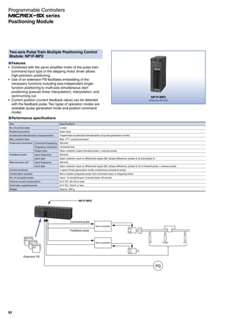
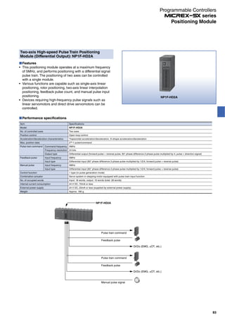
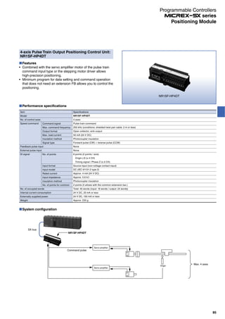
Pulse train output positioning control module
Pulse train positioning control module
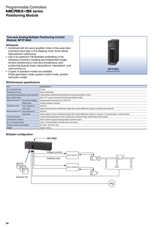
Analog command positioning control combined module
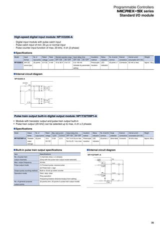
Model (ordering code)
NP1X3206-A
NP1X3206-W
NP1X3202-W
NP1X6406-W
NP1Y32T09P1-A
NP1Y32T09P1
NP1Y64T09P1
NP1Y32U09P1
NP1Y64U09P1
NP1W3206T
NP1W3206U
NP1W6406T
NP1W6406U
NP1F-HC2
NP1F-HC8
NP1F-HP2
NP1F-MP2
NP1F-MA2
Specifications
24 V DC, 32 points, 4 mA 0 ms to 100 ms variable, with 20 kHz x 4 ch. built-in pulse counter
24 V DC, 32 points, 4 mA 1 ms to 100 ms variable
5/12 V DC, 32 points, 3/9 mA, 1 to 100 ms variable
24 V DC, 64 points, 4 mA 1 ms to 100 ms variable
Tr. Sink, 24 V DC, 32 points, 0.12 A/point, 3.2 A/common, with 20 kHz x 4 ch. built-in pulse train output
Transistor sink, 12 to 24 V DC, 32 points, 0.12 A/point, 3.2 A/common
Transistor sink, 12 to 24 V DC, 64 points, 0.12 A/point, 3.2 A/common
Transistor source, 12 to 24 V DC, 32 points, 0.12 A/point, 3.2 A/common
Transistor source, 12 to 24 V DC, 64 points, 0.12 A/point, 3.2 A/common
24 V DC, 16-point source input, 12 to 24 V DC, Tr sink 16-point output
24 V DC, 16-point sink input, 12 to 24 V DC, Tr source 16-point output
24 V DC, 32-point bidirectional input, 12 to 24 V DC, Tr sink 32-point output
24 V DC, 32-point bidirectional input, 12 to 24 V DC, Tr source 32-point output
500 kHz x 2 ch, 90-degree phase difference 2-phase signal, pulse + directional signal, others
50kHz x 8 ch, 90-degree phase difference 2-phase signal, pulse + directional signal, others
Pulse train command 250 kHz x 2 ch.
2-axis pulse train command positioning control combined module output pulse: 250 kHz, Feedback pulse: 500 kHz
2-axis analog command positioning control combined module feedback pulse: 500 kHz
Note: " " indicates the length of multi-core cables and flat cables.
1:1m (standard), 2:2m, 3:3m
· Connection cable
Applied terminal block type
AU-CW41B1-11
No. of poles
40
Cable type
Multi-conductor cable
Flat cable
Connection cable type
AUX011-40
AUX021-40
Ordering code
LP911-40
LP921-40
43
Standard I/O module
Programmable Controllers
series](https://image.slidesharecdn.com/catalog-plc-fuji-190722092557/85/Catalog-PLC-Fuji-Electric-43-320.jpg)
![(Picture No. AF96-82)
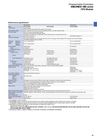
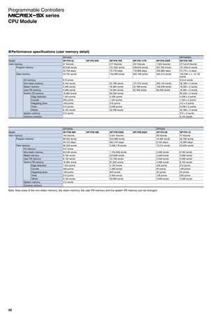
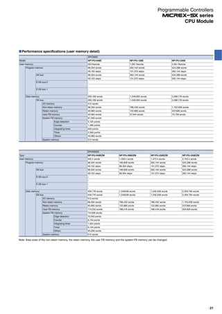
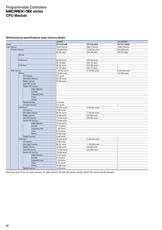
Performance specifications
Item
Operating duration
Recovery duration
Vibration
resistance
Impact
resistance
Operating ambient temperature
Relative humidity
Terminal screw size
External connection tightening torque
Mounting method
Applicable round-type crimp-style terminal
Connection wire
LED indication color
Coil surge protection element
Relay removal count
Insulation resistance (initial)
Voltage
resistance
Weight
Malfunction
Durability
Malfunction
Durability
Between contact coils
Between contacts with same polarity
Between contacts with different polarity
Performance
10 ms or less
10 ms or less
10 to 55 Hz, Duplex amplitude 1.0 mm
10 to 55 Hz, Duplex amplitude 1.0 mm
3 times each in X, Y, and Z directions to total 18 times
100 m/s2
200 m/s2
2 hours each in X, Y, and Z directions to total 6 hours
-25 to +55˚C (without condensation)
35 to 85%RH
M3
0.5 to 0.7 N∙m
Rail mounting (screw mounting also possible)
R1.25 to 3 (Max.6mm wide)
Max. 1.4
Operating indication: Red, Power indication: Green
Diode
50 times
100 MΩ or more (with 500 V DC megger)
2000 V AC, 1 minute
1000 V AC, 1 minute
2000 V AC, 1 minute
Approx. 200g
Type/model/ordering code
Model
(ordering code)
RS16E-DE04
RS16-DE04
RS16-DE04P
I/O
type
Input
Output
No. of
points
16 points
(1a x 16)
Rated
voltage
24 V DC
Common line handling on
connector side.
NPN compatible ( common)
NPN compatible ( common)
PNP compatible ( common)
Terminal Relay Application Table
Terminal relay
type
SPH
I/O module type
RS16E-DE04
NP1X3206-W
NP1X6406-W
RS16-DE04
NP1Y32T09P1
NP1Y64T09P1
RS16-DE04P
NP1Y32U09P1
NP1Y64U09P1
Rating
Opening section, connector side (for 1 point RB105)
Item
Rated load and rated voltage current
Rated thermal current
Contact resistance
Min. application load application
voltage current (P level reference value)
Electrical lifetime
Mechanical lifetime
RS16 (output) resistor
Resistance load
(cos = 1, L/R = 0 ms)
220 V AC 2 A
2A *1
30 mΩ or less
0.1 V 0.1 mA
200 thousand times
20 million times 300 thousand times 100 thousand times 60 thousand times
Inductive load
(cos = 0.4, L/R = 7 ms)
220 V AC 2 A
RS16E (input) resistor
Resistance load
(cos = 1, L/R = 0 ms)
24 V DC 1A
1A *2
30 mΩ or less
0.1 V 0.1 mA
-
Inductive load
(cos = 0.4, L/R = 7 ms)
24 V DC 1A
*1 While the used relay (RB105) is a product to use the rated thermal current 5 A, the rated thermal current of the main unit is 2 A because of the terminal relay unit structure.
*2 While the used relay (RB105) is a product to use the rated thermal current 5 A, the rated thermal current of the main unit is 1 A because of the terminal relay unit structure.
24 V DC 2A 24 V DC 2A
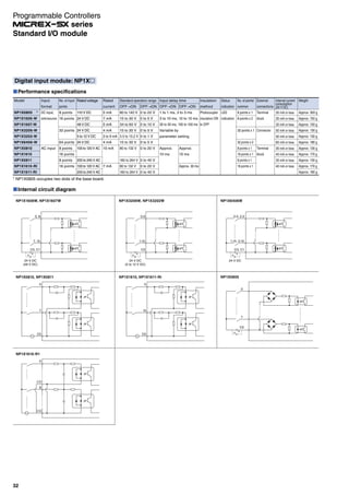
Load
Features
Min. width of 110 mm has been achieved.
The external dimension is as compact as 110 mm (W) x 52
mm (D) x 37 mm (H).
Push-set terminal facilitates tightening screws.
Push-set terminal is used in the terminal section, eliminating the
screw tightening time and preventing screws from being lost.
LED operation indication facilitates I/O ON/OFF operation check.
Operation indication LED is arranged in 1:1 correspondence
with the relay. This makes the ON/OFF relay operation status
clear at a glance.
Two types of relays available for output and input.
With surge protection diode provided.
Terminal cover is installed as standard allowing device No.
indication.
With the built-in relay remover
Used for both DIN rail installation and rear-side screw mounting
Terminal relay
(Model by Fuji Electric FA Components & Systems Co., Ltd.)
Ambient temperature: 20°C
Operation coil I/O specifications (for 1 point RB105)
Rated voltage
5 V DC
24 V DC
Rated current
[mA]
40
8.3
Coil resistance
[Ω]±10%
125
2,880
Pick-up voltage
70% of rated voltage or less
70% of rated voltage or less
Return voltage
10% of rated voltage or more
10% of rated voltage or more
Max. allowable voltage
110% of rated voltage
110% of rated voltage
Power consumption [W]
Per 1 points
0.2
0.2
Per 16 points
3.2
3.2
Note: The current flowing in the LED is about 1 mA. Add each of amperage values for the power capacity calculation.
45
Standard I/O module
Programmable Controllers
series](https://image.slidesharecdn.com/catalog-plc-fuji-190722092557/85/Catalog-PLC-Fuji-Electric-45-320.jpg)
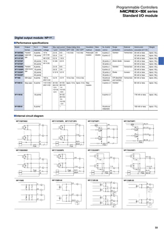
![Internal connection diagram
−
−
E
F
D
C
A
B
9
8
6
7
5
4
2
3
1
0
COM
COM
COM
COM
+
−
GND
GND
VCC
VCC
Connector
Connector pin
arrangement
(Terminal-relay
common)
▲
20
19
18
17
16
15
14
13
12
11
10
9
8
7
6
5
4
3
2
1
20
10
18
17
16
15
14
13
12
11
8
7
6
5
4
3
2
1
9
19
Terminal block
RS16-DE04
(output, NPN compatible product)
COM
COM
COM
COM
+
−
GND
GND
VCC
VCC
Connector
19
9
18
17
16
15
14
13
12
11
8
7
6
5
4
3
2
1
10
20
Terminal block
RS16-DE04P
(output, PNP compatible product)
E
F
D
C
A
B
9
8
6
7
5
4
2
3
1
0
E
F
D
C
A
B
9
8
6
7
5
4
2
3
1
0
COM
COM
COM
COM
−
+
+
+
+
+
−
−
−
−
−
−
−
−
−
−
−
−
−
−
GNDGND
VCC
VCC
Connector
20
10
18
17
16
15
14
13
12
11
8
7
6
5
4
3
2
1
9
19
Terminal block
RS16E-DE04
(input, NPN compatible product)
INside
OUTsideINside
INside
INside
INside
OUTside
OUTside
INside
Terminal relay cable
Type/model/ordering code
Type
Cable with connectors (1:2)
For MICREX-SX (for input, output)
Cable length (L)
1,000 mm
2,000 mm
3,000 mm
Model (ordering code)
RS910M2-0104
RS910M2-0204
RS910M2-0304
Outline dimensional drawing
2- 4.2
(M3 to M4 screw hole for screw mounting)
14.8 91 4.2
111 (min. installation pitch)
43.5
42.5 (for rail height 7.5)
50 (for rail height 15)
Connector
HIROSE Electric HIF3CA—20PA—2.54DSA
M3×22
Power indicator lamp
(green)
Operation indicator lamp
(Red)
110
4.752
Remover
Panel hole dimension
(For panel-mounting)
35 mm width
JIS rail
33
37
(39)
[Units: mm]
Cable outline wiring diagram
Controllerside
Terminalrelayside
AB
20 pin (A) 40 pin
1
2
3
4
5
6
7
8
9
10
11
12
13
14
15
16
17
18
19
20
A20
A19
A18
A17
A16
A15
A14
A13
A 1
B 1
A12
A11
A10
A 9
A 8
A 7
A 6
A 5
A 3
B 3
I/O
signal
I/O
signal
20 pin (B) 40 pin
1
2
3
4
5
6
7
8
9
10
11
12
13
14
15
16
17
18
19
20
B20
B19
B18
B17
B16
B15
B14
B13
A 2
B 2
B12
B11
B10
B 9
B 8
B 7
B 6
B 5
A 4
B 4
Power
supply (-)
Power
supply (+)
Power
supply (-)
Power
supply (+)
Viewfromtheengagementsurface
20-pinconnector:HIF3BA-20D-2.54R(HiroseElectricCo.,Ltd.product)
40-pinconnector:FCN367J40-AU/F(FujitsuComponentLimitedproduct)
Viewfromtheengagementsurface
Bcolumn
Acolumn
<Wiring>
L
150
Straight line length (without curve)
2019181716151413121110987654321
2019181716151413121110987654321
20191817161514131211
10987654321
20191817161514131211
10987654321
46
Standard I/O module
Programmable Controllers
series](https://image.slidesharecdn.com/catalog-plc-fuji-190722092557/85/Catalog-PLC-Fuji-Electric-46-320.jpg)
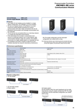
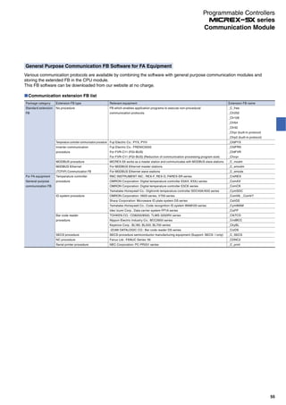
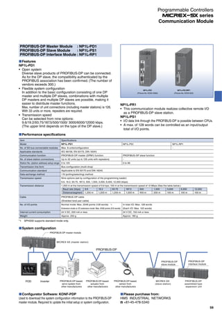

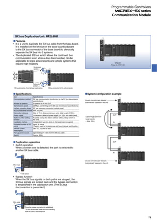
![SX Bus Electric Repeater Unit: NP2L-RP1
Features
SX bus connection using another 25 m electric cable is
enabled by correcting the signal waveforms of the SX bus
electric cable.
Up to three units can be used in one SX system, increasing
the total extension length of the SX bus electric cable to a
max. of 100 m.
NP2L-RP1
(Picture No. KD03-017)
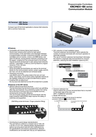
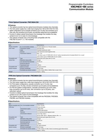
System configuration example
The length of SX bus cable is 25 m or less
SX bus electric repeater
The length of SX bus cable is 25 m or lessThe length of SX bus
cable is 25 m or less
Up to 10 units that supply power from the SX bus cable can be connected per an electric repeater.
Up to 10 units that supply
power from the SX bus
cable can be connected.
Up to 10 units that supply power from the SX bus cable can be
connected per an electric repeater.
Up to 20 units can be connected if there is an electric repeater
on the both sides.
Servo amplifier
Servo amplifierRemote I/O
Remote I/O
24 V DC
24 V DC
Specifications
Item
Rated power supply voltage
Power supply voltage tolerance
Current consumption
Dimension (W×H×D) [mm]
SX bus transmission distance
Max. number of usable units
Weight
Specifications
24 V DC
22.8 to 26.4 V DC
Max. 1470 mA
50 × 95 × 95
25 m
3 units
Approx. 150 g
Remarks
Uses externally supplied power
Uses externally supplied power
When connecting servo and inverter: 24 to 26.4 V DC
Current consumption: Approx. 70 mA
24 V power supply to the SX bus cable: Up to two 700 mA systems
—
Total extension of the SX bus cable connected to each connector
The max. total extension of the SX bus cable is 100 m.
72
Communication Module
Programmable Controllers
series](https://image.slidesharecdn.com/catalog-plc-fuji-190722092557/85/Catalog-PLC-Fuji-Electric-72-320.jpg)
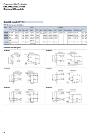
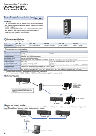
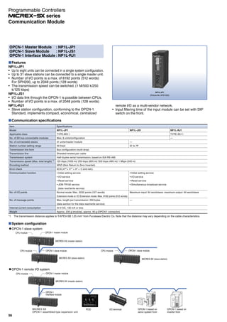
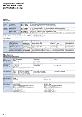
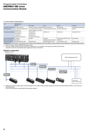
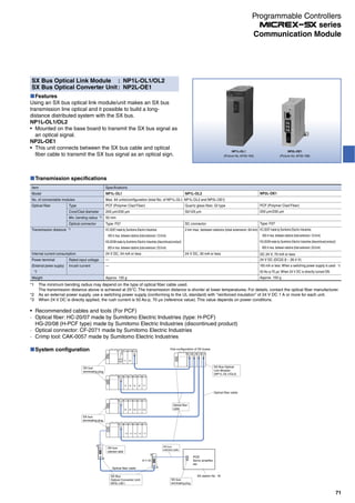
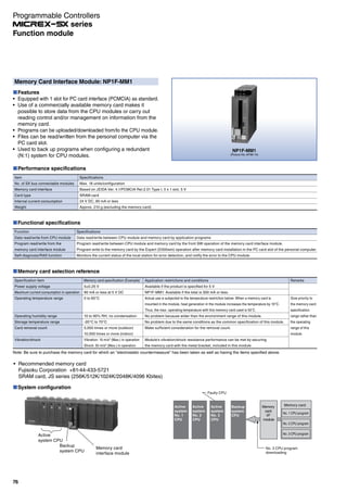
![Configuration example
Note 1: The cable symbols shown in the figure above are as follows:
: Optical fiber cable (main)
: Optical fiber cable (redundancy backup)
: Cable for a T-link or cable for a P-link
Note 2: Connect a terminal resistor for a T-link (100 Ω) or for a P-link (75 Ω) to each unit marked with in the figure.
Note 3: When a cable for a T-link or for a P/PE-link is not connected to an optical converter, connect a terminal resistor to the converter.
System Loop connection
Economical configuration
with the least number of
optical converters.
Cascade connection 2 (single)
Suitable for long-distance
transmission.
Cascade connection 3 (redundant)
Ensures a higher degree of reliability
by adding redundancy backup to the
system shown on the left.
Star connection (can be redundant)
a Minimizes down units in the system.
b Consists of units positioned at
a long distance from one
another in a radial pattern.
OCT:
Optical
converter
for T-link
OCP:
Optical
converter
for P/PE-link
Cascade connection 1
Suitable for long-distance
transmission.
[Constraint]
OCT: Up to 3 units
Loop wiring can maintain
transmission even if an
optical fiber cable between
optical converters is broken.
If an error occurs in any of the optical converters, transmission will be interrupted
at the faulty unit.
[Constraint]
OCT: Up to 16 units
[Constraint]
OCT: Up to 16 units
[Constraint]
OCT: Up to 16 units
[Constraint]
OCP: Up to 16 units (P-link)
64 units (PE-link)
[Constraint]
OCP: Up to 8 pairs (16 units) (P-link)
Up to 32 pairs (64 units) (PE-link)
[Constraint]
OCP: Up to 16 units (P-link)
64 units (PE-link)
[Constraint]
OCP: Up to 16 units (P-link)
64 units (PE-link)
[Constraint]
OCT: Up to 8 pairs (16 units)
The effect of an optical converter
error is limited to the faulty unit,
allowing for a highly reliable
system.
Operation in
case of
an error
Example of
an optical
T-link system
configuration
Example of
an optical
P/PE-link
system
configuration
Features
SPH
OCT
OCT
SPH
OCT
SPH
SPH
SPH
SPH
OCT
OCT
SPH
SPH
OCT
SPH
OCT
SPH
SPH SPH
SPH
OCP
OCP
SPH
OCP
SPH
SPH
OCP
SPH
SPH
SPH
SPH
OCP
OCP
SPH
SPH
OCP
SPH
OCP
SPH
OCP
SPH
SPH SPH SPH
SPH
OCT
OCT
SPH
OCT OCT
SPH
SPH
SPH
SPH
OCP OCP
SPH
OCP
SPH
OCP OCPOCP
SPH
SPH
SPH
SPH
OCT OCT OCT
OCT
SPH
OCT OCT
SPH
SPH
SPH
SPH
SPH
Electric power
3 or more OCTs: Max. 500 m
2 or fewer OCTs: Max. 1 km
SPH
OCP OCP OCP
OCP
SPH
OCP OCP
SPH
SPH
SPH
SPH
SPH
Electric power
Max. 250 m
SPH
OCT
OCT
SPH
SPH
OCT OCT
SPH
SPH
SPH
SPH
OCT
Optical T-link and P/PE-link Systems
The optical T-link and P/PE-link systems ensure a superior network configuration with distinguished noise resistance by making use
of an optical converter and optical fiber cables.
The optical T-link and P-link systems have the following features.
System configurations, such as redundant optical lines, can be established.
Since an electric transmission system and an optical transmission system can be mixed, you can build an economical system by
adopting optical transmission systems only for the required portions.
Optical link systems as shown in the table below can be configured according to your application.
74
Communication Module
Programmable Controllers
series](https://image.slidesharecdn.com/catalog-plc-fuji-190722092557/85/Catalog-PLC-Fuji-Electric-74-320.jpg)

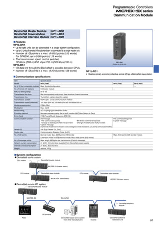
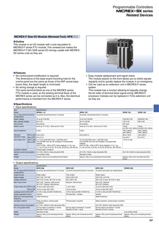
![W1
W2
W3
Dimensions
Model
Mounting dimensions of base unit
Mounting dimensions of base unit
Outside dimensions of SPH mounting board
Frame set
NP8REFSS-08
480
465
485
NP8REFSS-06
407
392
377
NP8REFSS-04
334
319
310
NP8REFSS-02
261
246
240
[Unit: mm]
Dimensions
MICREX-F F250/F120S/F140S/F150S/F120H/80H series compatible
Mounting example with the frame set (base unit + SPH mounting board)
· Base unit (mounting 1 SX base unit)
oNL
ERR
oNL
ERRERR
oNL
15
6 7
10 11 12 13
2 3 54
148
0
ERR
oNL
9
1
8 9 10 11
0 21 3
ERR
oNL5
13
431 20
12111098
76
1514 14
4 5
1312
76
15
oNL
ERR
31 20
1098 1115
7
12
4
13
5 6
14 1214 15
6 7
8 9 10 11 12
0 21 3 4
ERR
oNL
13
5 oNL
ERR
5
13
431 20
12111098
6
14 8 9 10 11
0 21 3 4
ERR
oNL7
15
764 5
1514131214 15
6 7
13
5 1 20oNL
1098ERR
3
11
W3
280
W1
W2
108
291
(82) 102
50
5 (M4 mounting screw)
· Base unit (mounting 2 SX base units)
355
W1
oNL
ERR
oNL
ERRERR
oNL
15
6 7
10 11 12 13
2 3 54
148
0
ERR
oNL
9
1 5
13
431 20
12111098
76
1514 8 9 10 11
0 21 3
ERR
oNL
14
4 5
1312
76
15
oNL
ERR
31 20
1098 1115
7
12
4
13
5 6
14 14 15
6 7
8 9 10 11 12
0 21 3 4
ERR
oNL
13
5
12
oNL
ERR
5
13
431 20
12111098
6
14 8 9 10
0 21
ERR
oNL7
15 11
3 4 4
12
765
15141314 15
6 7
13
5 1 20oNL
1098ERR
3
11
oNL
ERR
oNL
ERRERR
oNL
15
6 7
10 11 12 13
2 3 54
148
0
ERR
oNL
9
1
8 9 10 11
0 21 3
ERR
oNL5
13
431 20
12111098
76
1514 14
4 5
1312
76
15
oNL
ERR
31 20
1098 1115
7
12
4
13
5 6
14 1214 15
6 7
8 9 10 11 12
0 21 3 4
ERR
oNL
13
5 oNL
ERR
5
13
431 20
12111098
6
14 8 9 10
0 21
ERR
oNL7
15 11
3 4 4
12
765
15141314 15
6 7
13
5 1 20oNL
1098ERR
3
11
291
(82) 108 102
50
Base adapter type Dimension (mm)
Width of the entire base
adapter
F70 base mounting holes (Number of slots) SX base mounting holes
(Number of slots)
W W1 W2 W3 W4
NP8RE70B-02 207 189(2) - - 115(3)
NP8RE70B-04 277 189(2) 259(4) - 220(6)
NP8RE70B-06 347 189(2) 259(4) 329(6) 290(8)
NP8RE70B-08 417 259(4) 329(6) 408(8) 395(11)
NP8RE70B-10 487 329(6) 408(8) 469(10) 465(13)
MICREX-F F70 series compatible
W
140
W4 (SPH base board mounting hole)
31.836.2
85
28
W2
W3
W1
Programmable Controllers
series
105
Related Devices](https://image.slidesharecdn.com/catalog-plc-fuji-190722092557/85/Catalog-PLC-Fuji-Electric-105-320.jpg)
![Programmable Controllers
series
108
Analog input specifications
Item Specifications
Model NP8AX-340MR NP8AX-344
Input channel 8 channels
Analog input range 0 to 5 V 0 to 10 V -5 V to +5 V -10 V to +10 V 0 to 20mA
Digital output value 0 to 4000 -2000 to 2000 0 to 4000
Digital output model BCD 4 digits with ± sign/BIN switching
Resolution 12 bits
No. of occupied words 8 words (input)
Overall accuracy ±0.2% (0 to 55 °C) ±0.3% (0 to 55 °C)
Response time 12 ms or less/8 points + tact cycle (ms)
Internal current
consumption
24 V DC, 40mA
External terminal Detachable terminal block (M3.5, 20 poles)
Depth Standard model
Weight Approx. 500 g or less (not including terminal block)
Mounting dimensions of base board
Type External dimension (W x H x D) [mm] Weight [g] Base board for SX Fixing screw mounting space (W x H) [mm]
NP8B-13 508 x 260 x 36 1,500 13 slots 465 x 150
Same as FSB128/FSB110H
NP8B-11 438 x 260 x 36 1,300 11 slots 392 x 150
Same as FSB126/FSB088H
NP8B-08 336 x 260 x 36 1,000 8 slots 319 x 150
Same as FSB124/FSB086H
NP8B-06 263 x 260 x 36 800 6 slots 246 x 150
Same as FSB084
Related Devices](https://image.slidesharecdn.com/catalog-plc-fuji-190722092557/85/Catalog-PLC-Fuji-Electric-108-320.jpg)
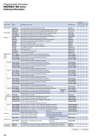

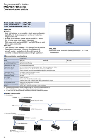
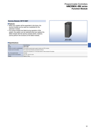
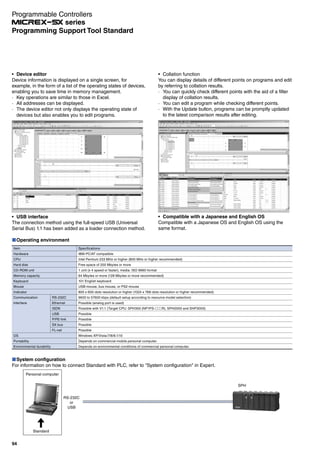
![Please sign up for a free
Fe Library membership.
If you are a registered member, you
can access technical information free of
charge, such as user’s manual, guide,
and CAD data.
If you login to the
Fe Library, you can
download data.
Please select the document you would like
to see based on your model.
[CPU Module User Manual Screen][CPU Module Screen]
[Expert (D300win)]
Support tools related to development efficiency
[Standard]
Support tools related to operability
You can download the upgraded (latest) version of the programming support tool.
You can view the model lineup and
technical document types of the
selected modules.
* Fe Library is a download site for the product documents provided by Fuji Electric Co., Ltd.
https://felib.fujielectric.co.jp/download/index.htm?site=global&lang=en](https://image.slidesharecdn.com/catalog-plc-fuji-190722092557/85/Catalog-PLC-Fuji-Electric-125-320.jpg)


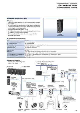
The Fuji Integrated Controllers series offers programmable controllers with high program capacity, supporting diverse system configurations from small to large scale. These controllers conform to IEC 61131 standards, enabling high-speed machine control and easy integration with various open networks. Additionally, they feature advanced programming support tools, multi-CPU configurations for redundancy, and high-speed e-SX bus capabilities, enhancing performance and reliability in automated systems.


