Dr. M. MedrajMech. Eng. Dept. - Concordia University Mech 221 lecture 1 [5]
- Civilization strongly linked with materials
Stone age, iron age, bronze age …nuclear age,
information age
Introduction: Historical Perspective
- Sumerians: ceramics
- Egyptians: lime
- Anatolians: Iron (12th century BC)
- The earliest known Bronze is from what is now Iran
and Iraq
Dr. M. Medraj Mech. Eng. Dept. - Concordia University Mech 221 lecture 1 [6]
Technological advances have been materials driven:
– Transportation; engines, airframes, auto bodies
– Space exploration; shuttle tiles, high temp alloys
– Energy; solar power, batteries
– Communications; semiconductors
• Military uses Commercial uses
Introduction
Dr. M. Medraj Mech. Eng. Dept. - Concordia University Mech 221 lecture 1 [7]
What is Materials Science ?
- Structure-property correlations
- Design the structure of a material to impart some
desired properties
- Relationships between structure and
………….. of materials
What is Materials Engineering ?
Dr. M. Medraj Mech. Eng. Dept. - Concordia University Mech 221 lecture 1 [8]
• Mechanical
• ……….
• ……….
• ……….
• ……….
Property: Response of a material to
an external effect, such as
Properties are independent of material ..………………
Introduction
3.
Dr. M. MedrajMech. Eng. Dept. - Concordia University Mech 221 lecture 1 [9]
Structure
atomic
molecular
Microscopic
Atomic processing
Properties
General Course Outline:
Dr. M. Medraj Mech. Eng. Dept. - Concordia University Mech 221 lecture 1 [10]
Course Outline
Exam1 lecture
Review 2 lect’s
Total: 26 lectures
23
Topic Lectures
• Introduction: Basic characteristics of metals, ceramics,
polymers and composites, engineering design criteria
1
• Chemistry Review: Atomic structure and Interatomic Bonding 1
• The structure of Crystalline Solids 3
• Imperfections in Crystals 2
• Diffusion 1
• Mechanical Properties of Metals 3
Midterm Exam
• Phase Diagrams 3
• Structure, Properties, Applications and Processing of Ceramics 2
• Polymer Structures 1
• Applications and Processing of Polymers 1
• Thermal, Electrical, Magnetic and Optical Properties 4
Dr. M. Medraj Mech. Eng. Dept. - Concordia University Mech 221 lecture 1 [11]
Why study Materials Science?
(1) Important to understand capabilities and limitations
of materials:
• The following are just a few examples of catastrophic
failure caused by a lack of fundamental understanding of
materials, their properties, and failure modes.
Dr. M. Medraj Mech. Eng. Dept. - Concordia University Mech 221 lecture 1 [12]
Liberty ships (WWII) D-B-T in BCC Fe (metal)
Challenger (1986) failure of an O-ring seal (polymer)
Examples of Catastrophic Failure
4.
Dr. M. MedrajMech. Eng. Dept. - Concordia University Mech 221 lecture 1 [13]
Hyatt Regency (KC)
walkway collapse (1981)
Overstressed
steel support
rods
(underdesigned)
Alaska MD-80 crash (1999)
Excessive
wear on
stabilizer
jackscrew
Examples of Catastrophic Failure
Dr. M. Medraj Mech. Eng. Dept. - Concordia University Mech 221 lecture 1 [14]
• Tacoma Narrows Bridge
Collapse (1940)
poor design – …………
• de Havilland Comet (first commercial jet) (1954 – 55)
metal fatigue, aggravated by high stresses around rivet
holes near window openings
• United DC-10 crash (Sioux City, IA) (1989)
inclusion and cracking in primary #2 engine turbine blade
Examples of Catastrophic Failure
Dr. M. Medraj Mech. Eng. Dept. - Concordia University Mech 221 lecture 1 [15]
(2) An understanding of Materials Science helps us to
design better components, parts, devices, etc.
• how do you make something stronger or lighter?
• how do elements come together to form alloys?
• why do some materials have vastly different properties
than others?
(3) It is interesting and helps to make you a more informed person
Why Study Materials Science?
Dr. M. Medraj Mech. Eng. Dept. - Concordia University Mech 221 lecture 1 [16]
There are 3 major classes:
1. Metals
Pure metallic elements or
Combination of metallic elements (alloys)
Large number de-localized electrons (conduct electricity)
2. Ceramics
- Molecules based on bonding between metallic and
non-metallic elements (including oxides, nitrides, carbides)
- Typically insulating and refractory
3. Polymers
Many are organic compounds
Chemically based on C, H, other non-metals
Large molecular structures
Classes of Materials
5.
Dr. M. MedrajMech. Eng. Dept. - Concordia University Mech 221 lecture 1 [17]
Semiconductors (ceramics)
Intermediate electrical properties
Composites (all three classes)
Combinations
Bio Materials (all three classes)
Materials compatible with body tissue
Sub-Classes of Materials
Dr. M. Medraj Mech. Eng. Dept. - Concordia University Mech 221 lecture 1 [18]
Materials Design:
– design of new materials to meet new requirements.
– design of new materials with a unique set of properties.
– design can include the development of a new or better
processes for manufacturing of new or existing materials.
Trends in Materials Use
Materials ……
Materials …….
Introduction
Dr. M. Medraj Mech. Eng. Dept. - Concordia University Mech 221 lecture 1 [19]
MATERIALS SELECTION
Selection of the correct/appropriate or best material for the job.
Short List:
(a) Availability ?
(b) Properties ?
(c) …… ? (Usually determining factor).
In many cases a more suitable material is available but at an
increased cost, e.g.
Car bodywork/exhausts
- “mild” steel, rusts,
- stainless steel, lasts much longer
Cost not big problem in defence, sport, medicine.
Introduction
Dr. M. Medraj Mech. Eng. Dept. - Concordia University Mech 221 lecture 1 [20]
Next time: Chemistry Review
6.
Dr. M. MedrajMech. Eng. Dept. - Concordia University Mech 221 lecture 2/1
• Classes of materials
• Chemistry review
• Review of atomic structure
• Review of the periodic table
• Density, atomic # & wt, mole, Avogadros #
• Bonding forces and energy
Outline
Dr. M. Medraj Mech. Eng. Dept. - Concordia University Mech 221 lecture 2/2
POLYMERS CERAMICS METALS
DUCTILITY Varies Poor Good
High
CONDUCTIVITY
(ELECTRICAL & THERMAL)
Low Low
HARDNESS/STRENGTH
Low –
medium ……….. Medium–
high
CORROSION RESISTANCE Fair – good Good Fair – poor
STIFFNESS Low High Fair
FRACTURE TOUGHNESS
Low –
medium
Low High
MACHINABILITY Good ……… ……..
Classes of materials
Dr. M. Medraj Mech. Eng. Dept. - Concordia University Mech 221 lecture 2/3
• Electronic structure (distribution of electrons in atomic orbitals)
• Number of electrons and ……………… (tendency for an
atom to attract an electron)
Why study bonding?
• Because the properties of materials (strength, hardness,
conductivity, etc..) are determined by the manner in which
atoms are connected.
• Also by how the atoms are arranged in space ……….
What determines the nature of the chemical bond
between atoms?
Dr. M. Medraj Mech. Eng. Dept. - Concordia University Mech 221 lecture 2/4
Based on earlier work of Rutherford and his
own from spectral emission studies
– Bohr atomic model
• electrons revolve around
nucleus in discrete orbitals
Bohr model of the atom: (1913)
Atomic Structure
7.
Dr. M. MedrajMech. Eng. Dept. - Concordia University Mech 221 lecture 2/5
BOHR ATOM
orbital electrons
n=3 2 1
Nucleus: Z = # protons
= 1 for hydrogen to 94 for plutonium
N = # neutrons
Atomic mass A ≈ Z + N
Adapted from Fig. 2.1,
Callister 6e.
Dr. M. Medraj Mech. Eng. Dept. - Concordia University Mech 221 lecture 2/6
Wave-mechanical atomic model
• Position of electron is imprecisely
known; only a probability distribution.
• Electron exhibits both particle and
wave characteristics
Bohr vs. Quantum-Mechanical Model: (1927)
Schroedinger, Heisenburg, Planck
and others developed this model
(wave mechanics), which allows a
more precise description of the atom.
Dr. M. Medraj Mech. Eng. Dept. - Concordia University Mech 221 lecture 2/7
Increasing Electronegativity
Dr. M. Medraj Mech. Eng. Dept. - Concordia University Mech 221 lecture 2/8
Electronegativity - each kind of atom has a certain attraction
for the electrons involved in a chemical bond. This "electron-
attracting" power of each atom can be listed numerically on an
electronegativity scale.
• http://www.webelements.com
Electronegativity was originally worked out by Linus Pauling in 1939
– see “The Nature of the Chemical Bond”
8.
Dr. M. MedrajMech. Eng. Dept. - Concordia University Mech 221 lecture 2/9
• Columns: Similar Valence Structure
Electropositive elements:
Readily give up electrons
to become + ions.
Electronegative elements:
Readily acquire electrons
to become - ions.
Adapted
from Fig. 2.6,
Callister 8e.
THE PERIODIC TABLE
inert
gases
accept
1e
accept
2e
give
up
2e
give
up
3e
give
up
1e
Dr. M. Medraj Mech. Eng. Dept. - Concordia University Mech 221 lecture 2/10
ELECTRONEGATIVITY
• Ranges from 0.7 to 4.0,
Smaller electronegativity Larger electronegativity
• Large values: tendency to acquire electrons.
Adapted from Fig. 2.7, Callister 8e. (Fig. 2.7 is adapted from Linus Pauling, The Nature of the
Chemical Bond, 3rd edition, Copyright 1939 and 1940, 3rd edition. Copyright 1960 by Cornell
University.
Dr. M. Medraj Mech. Eng. Dept. - Concordia University Mech 221 lecture 2/11
• High electronegativity strong tendency to accept an electron (i.e.,
Group VIIA: F, Cl)
The difference in electronegativity between two atoms determines
the resulting electron distribution and the type of bond
• Low electronegativity (called “electropositive”) strong tendency to
give up an electron, i.e., Group IA: Li, Na, K)
ELECTRONEGATIVITY
Dr. M. Medraj Mech. Eng. Dept. - Concordia University Mech 221 lecture 2/12
Density, Atomic # & Wt, Mole & Avogadros #
• Mole = number of particles
NA = ………….. part/mole
• Density
g/cm3 (most solids range ~ 1 - 23 g/cm3)
• Atomic number = number of protons (Z)
• Atomic weight (A)
g/mole
A number protons (Z) + neutrons (N)
Z+N
9.
Dr. M. MedrajMech. Eng. Dept. - Concordia University Mech 221 lecture 2/13
Review Problems
• How many atoms in 6 grams of carbon?
• Calculate the volume of 1 mole of Au.
Useful tip: many problems can be worked by suitable
manipulation of density (g/cm3), atomic mass (g/mole), and
Avagadro’s number (atoms/mole) (use dimensional analysis!)
Dr. M. Medraj Mech. Eng. Dept. - Concordia University Mech 221 lecture 2/14
ELECTRON ENERGY STATES
Electrons...
• have discrete energy states
• tend to occupy lowest
available energy state.
Increasing
energy
n=1
n=2
n=3
n=4
1s
2s
3s
2p
3p
4s
4p
3d
• Most elements: Electron configuration …………...
Stable electron configurations...
• have complete s and p subshells
• tend to be …………..
Dr. M. Medraj Mech. Eng. Dept. - Concordia University Mech 221 lecture 2/15
Net force is given by the sum of an
attractive force and a repulsive force
Potential is given by the integral of the net
force curve with respect to distance:
Note: equilibrium separation occurs
where the net force = 0
dr
F
E
Bonding Forces and Energies
repulsive, attractive, and net forces
repulsive, attractive, and net energies
Bond length, r
F
F
r
Dr. M. Medraj Mech. Eng. Dept. - Concordia University Mech 221 lecture 2/16
Indicates how much energy must be supplied to completely
disassociate the two atoms
Depth of the potential well indicates bonding strength
• Deep well
• Shallow well
Bonding energy: Minimum of the potential vs. distance curve.
………….. bonded
……….. bonded
Bonding Forces and Energies
Eo=
“bond energy”
Energy (r)
ro
r
unstretched length
10.
Dr. M. MedrajMech. Eng. Dept. - Concordia University Mech 221 lecture 2/17
• State as function of bonding energy
• Solid (…….)
• Liquid (……….……)
• Gaseous (……..)
Bond Energy
The higher the bond energy
• ………….
• ………….
Dr. M. Medraj Mech. Eng. Dept. - Concordia University Mech 221 lecture 2/18
Next time:
Types of Atomic Bonds
11.
Dr. M. MedrajMech. Eng. Dept. - Concordia University Mech 221 lecture 3/1
Outline:
• Types of bonds:
- Ionic
- Covalent
- Metallic
- Secondary bonding
• Examples:
- relation between bond energy and properties
• Summary
Dr. M. Medraj Mech. Eng. Dept. - Concordia University Mech 221 lecture 3/2
IONIC BONDING
Na (metal)
unstable
Cl (nonmetal)
unstable
electron
+ -
Coulombic
Attraction
Na (cation)
stable
Cl (anion)
stable
• Occurs between + and - ions.
• Requires electron transfer.
• Large difference in ……………………. required.
• Example: NaCl
Dr. M. Medraj Mech. Eng. Dept. - Concordia University Mech 221 lecture 3/3
• Predominant bonding in Ceramics
Give up electrons Acquire electrons
EXAMPLES: IONIC BONDING
CsCl
MgO
CaF2
NaCl
Dr. M. Medraj Mech. Eng. Dept. - Concordia University Mech 221 lecture 3/4
Ionic: electron transfer from one atom (cation) to the other (anion).
• More likely between atoms with large electronegativity
differences
• Typically found between metal and non-metal atoms:
NaCl, KF, CsBr, MgO…
Typical bonding energies: 600 to 1500 KJ/mole (3 to 8 eV/atom)
IONIC BONDING: Summary
Typical characteristics of ionically-bonded materials:
• ……. melting temperature
• Hard
• Brittle
• ……... (electrical and thermal)
12.
Dr. M. MedrajMech. Eng. Dept. - Concordia University Mech 221 lecture 3/5
COVALENT BONDING
• Requires shared electrons
C: has 4 valence e,
needs 4 more
H: has 1 valence e,
needs 1 more
Electronegativities
are comparable.
• Example: CH4
shared electrons
from carbon atom
shared electrons
from hydrogen
atoms
H
H
H
H
C
CH4
Adapted from Fig. 2.10, Callister 6e.
Dr. M. Medraj Mech. Eng. Dept. - Concordia University Mech 221 lecture 3/6
• Molecules with nonmetals
• Molecules with metals and nonmetals
• Elemental solids (RHS of Periodic Table)
• Compound solids (about column IVA)
EXAMPLES: COVALENT BONDING
3.5 -
SiC
C(diamond)
H2O
C
2.5
H2
Cl2
F2
Si
1.8
GaAs
Ge
1.8
column
IVA
Sn
1.8
Pb
1.8
Dr. M. Medraj Mech. Eng. Dept. - Concordia University Mech 221 lecture 3/7
Covalent: electron sharing between atoms each atom contributes (at
least) one electron to the bond
• Each atom tries to achieve a more stable orbital filling configuration
• Tends to be a highly directional bond
• Gives rise to a fixed orientation of the atoms
• Shared electrons may be considered to belong to each atom
COVALENT BONDING: Summary
Dr. M. Medraj Mech. Eng. Dept. - Concordia University Mech 221 lecture 3/8
Note how the sharing of electrons acts to complete the filling of
electronic states in each respective atom:
1s2(2s22p2) 1s2(2s22p6)
Carbon:
Difficult to assign general characteristics to covalently-bonded materials:
• Bonds may be strong (diamond, Tm > 3550C) or weak (Bi, Tm = 270C)
• Materials may be conductive (GaAs) or insulating (diamond)
COVALENT BONDING: Summary
13.
Dr. M. MedrajMech. Eng. Dept. - Concordia University Mech 221 lecture 3/9
% ionic character = x 100%
where XA, XB are the electronegativities of the A and B atoms, respectively.
}]
)
(
25
.
0
exp{
1
[ 2
B
A X
X
MOST MATERIALS ARE NEITHER 100% IONIC NOR 100% COVALENT
Example:
Compute the percentage ionic character of the interatomic bonds for
TiO2 and ZnTe.
• For ZnTe, XZn = 1.6 and XTe = 2.1, and therefore,
• For TiO2, XTi = 1.5 and XO = 3.5, and therefore,
The electronegativities of the elements are found in Figure 2.7
Ionic Character
Dr. M. Medraj Mech. Eng. Dept. - Concordia University Mech 221 lecture 3/10
METALLIC BONDING
• Arises from a sea of donated valence electrons
(1, 2, or 3 from each atom).
• Primary bond for (not surprisingly) metals and their alloys
+ + +
+ + +
+ + +
Adapted from Fig. 2.11, Callister 6e.
• Valence electrons are not bound to any
specific atom but are free to drift
throughout the material
• Active bonding electrons form an
“electron sea”
Dr. M. Medraj Mech. Eng. Dept. - Concordia University Mech 221 lecture 3/11
• Metallic bonding can be either weak (68 kJ/mole or 0.7 eV/atom for Hg) or
strong (850 kJ/mole or 8.8 eV/atom for W)
• Metallic bonding gives rise to high electrical and thermal conductivity
• Metallic bonding also gives rise to ductility (at least more than in most covalent
and ionic solids). Think about why this might be so?.
The electrons are loosely held since each atom has several unoccupied
valence orbitals; it is relatively easy for the electrons to move about.
In this manner the electrons allow atoms to slide past each other.
METALLIC BONDING
Dr. M. Medraj Mech. Eng. Dept. - Concordia University Mech 221 lecture 3/12
Secondary Bonding
• Van der Waals bonding
• Bond energy is very weak compared to others
Compare typical secondary bonding strengths (10 kJ/mole) with typical primary
bonding strengths (50 to 1000 kJ/mole)
• Exists between almost all atoms and molecules
• Arise from atomic or molecular dipoles
– Physical bonds, not chemical
14.
Dr. M. MedrajMech. Eng. Dept. - Concordia University Mech 221 lecture 3/13
Unshielded, bare proton in H-
O, H-F and H-N bonds lead to
strong, hydrogen bonding
Thermal vibration fluctuations can disrupt charge symmetry which leads to a
dipole.
The presence of one dipole can induce a dipole in an adjacent molecule
(or atom) and so on.
• Hydrogen bonding is a special case of secondary bonding.
• The hydrogen bond is generally stronger than ……………..
Secondary Bonding
Polar molecule induced dipoles & hydrogen bonding
Due to permanent dipole moments in molecules
Dr. M. Medraj Mech. Eng. Dept. - Concordia University Mech 221 lecture 3/14
PROPERTIES FROM BONDING: TM
• Bond length, r
• Bond energy, Eo
F
F
r
Eo=
“bond energy”
Energy (r)
ro
r
unstretched length
• Melting Temperature, Tm
r
larger T m
smaller T m
Energy (r)
ro
Tm is larger if Eo is larger.
Dr. M. Medraj Mech. Eng. Dept. - Concordia University Mech 221 lecture 3/15
PROPERTIES FROM BONDING: E
• Elastic modulus, E cross
sectional
area Ao
L
length, Lo
F
undeformed
deformed
L
F
Ao
= E
Lo
Elastic modulus
r
larger Elastic Modulus
smaller Elastic Modulus
Energy
ro
unstretched length
E is larger if Eo is larger.
Dr. M. Medraj Mech. Eng. Dept. - Concordia University Mech 221 lecture 3/16
PROPERTIES FROM BONDING:
• Coefficient of thermal expansion,
is larger if Eo is smaller.
L
length, Lo
unheated, T 1
heated, T 2
= (T2-T1)
L
Lo
coeff. thermal expansion
r
smaller
larger
Energy
ro
15.
Dr. M. MedrajMech. Eng. Dept. - Concordia University Mech 221 lecture 3/17
• State as function of bonding energy
• Solid (…….)
• Liquid (……….……)
• Gaseous (……..)
Bond Energy
The higher the bond energy
• ………….
• ………….
the melting temperature
the hardness
…. etc
Dr. M. Medraj Mech. Eng. Dept. - Concordia University Mech 221 lecture 3/18
A comparison of the type of bonding found in different materials:
• For brass, the bonding is …….. since it is a metal alloy.
• For rubber, the bonding is ……… with some ……….
Rubber is composed primarily of carbon and hydrogen atoms
• For BaS, the bonding is predominantly ….. (but with some covalent character)
on the basis of the relative positions of Ba and S in the periodic table.
• For solid xenon, the bonding is ……………. since xenon is an inert gas.
• For nylon, the bonding is …….. with perhaps some ………..
Nylon is composed primarily of carbon and hydrogen
• For AlP the bonding is predominantly ……… (but with some ionic character)
on the basis of the relative positions of Al and P in the periodic table.
secondary bonding
Bonding Types: Summary
Dr. M. Medraj Mech. Eng. Dept. - Concordia University Mech 221 lecture 3/19
Next time:
Crystal structure, lattice directions and planes
16.
Dr. M. MedrajMech. Eng. Dept. - Concordia University MECH221 lecture 4/1
Outline:
• Crystalline versus amorphous structures
• Crystal structure
- Unit cell
- Coordination number
- Atomic packing factor
• Crystal systems
Dr. M. Medraj Mech. Eng. Dept. - Concordia University MECH221 lecture 4/2
ENERGY AND PACKING
• Non dense, random packing
• Dense, regular packing
Dense, regular-packed structures tend to have lower energy.
Energy
r
typical neighbor
bond length
typical neighbor
bond energy
Energy
r
typical neighbor
bond length
typical neighbor
bond energy
Dr. M. Medraj Mech. Eng. Dept. - Concordia University Mech 221 lecture 4/3
• atoms pack in periodic, 3D arrays
• typical of:
Crystalline materials...
-metals
-many ceramics
-some polymers
• atoms have no periodic packing
• occurs for:
Noncrystalline materials...
-complex structures
-rapid cooling
………….... = Noncrystalline
noncrystalline SiO2
Adapted from Fig.
3.18(b), Callister 6e.
crystalline SiO2
Adapted from Fig.
3.23(a), Callister 8e.
MATERIALS AND PACKING
Atoms can be arranged either in a regular, periodic array (i.e.,
long-range order) or completely disordered (amorphous).
Crystal Structure
• Motivation: Many of the properties of materials (especially
mechanical) are determined by the arrangement of the
constituent atoms.
This arrangement is called the material’s crystal structure.
• An important distinction…
– Atomic structure relates to the number of protons and
neutrons in the nucleus of an atom, as well as the number
and probability distributions of the constituent electrons.
– On the other hand, crystal structure pertains to the
arrangement of atoms in the crystalline solid material.
Dr. M. Medraj Mech. Eng. Dept. - Concordia University MECH221 lecture 4/4
17.
Dr. M. MedrajMech. Eng. Dept. - Concordia University MECH221 lecture 4/5
• We need a way to specify crystallographic directions and
planes.
• Let’s start with the hard sphere model (in which nearest
neighbor atoms “touch” each other)…
a
b
c
x y
z
To illustrate the concept of
crystal structure and lattice
systems, we first identify a
coordinate system (x, y, z):
We can’t specify directions or planes without knowing
what the reference system is.
Crystal Structure
Dr. M. Medraj Mech. Eng. Dept. - Concordia University MECH221 lecture 4/6
x y
z
Now place an atom at each corner…
a
b
c
This represents the “hard sphere”
model of a ……………….……. crystal
system
a
b
c
x y
z
• Atoms “touch” along the crystal axes
• These directions are referred to as “close-
packed” in the simple cubic system
not many examples of simple cubic systems in nature, except for Po
The above diagram represents a simple cubic ………..
Crystal Structure
• A unit cell is the smallest entity that exhibits the chemical and
………………. properties of the material.
Dr. M. Medraj Mech. Eng. Dept. - Concordia University MECH221 lecture 4/7
What is Unit Cell?
Definition:
the length of each unit cell axis is called a ……………..
– In cubic systems, all three orthogonal lattice parameters are equal
– Lattice parameters are typically on the order of a few Angstroms (or a
few tenths of a nanometer)
– Unit cells are the most elementary arrangement of atoms
which can generate the entire crystal upon application of
suitable translation, rotation, mirror, or inversion operations.
Dr. M. Medraj Mech. Eng. Dept. - Concordia University Mech 221 lecture 4/8
How many atoms does the simple cubic unit cell contain?
You should be able to convince yourself that a simple cubic
structure contains … atom/unit cell.
(Remember, a part of each atom is shared by another unit cell!)
8
2
c
f
i
N
N
N
N
Where: Ni = # interior atoms,
Nf = # face atoms,
Nc= # corner atoms
• The number of atoms/unit cell is an important quantity and determines
many physical properties.
• In general, the number of atoms/unit cell, N, is given by
Simple Cubic Unit Cell
18.
• volume ofthe unit cell = a3
– where a is the lattice parameter
• coordination # = 6
– for simple cubic structures
Dr. M. Medraj Mech. Eng. Dept. - Concordia University MECH221 lecture 4/9
CN is the number of nearest-neighbor atoms
Coordination number is important in determining the
structure of crystalline materials.
Large atoms tend to have large CN, small atoms usually
have small CN
it’s easier to surround a big atom with lots of atoms than a
smaller one.
Simple Cubic Unit Cell
Dr. M. Medraj Mech. Eng. Dept. - Concordia University Mech 221 lecture 4/10
We no longer have a simple cubic structure but instead, a …………
…………..….. (BCC) structure
Now, suppose we add another
atom at the center of the cube
Examples of BCC systems: Cr, W, Mo, Ta, Fe (Fe stable below 912C)
Notice that in the BCC structure, atoms touch along the body
………….. These are the close-packed directions in the body-
centered cubic structure.
BCC unit cells have a CN = ……
Body Centered Cubic Unit Cell
Dr. M. Medraj Mech. Eng. Dept. - Concordia University MECH221 lecture 4/11
Atomic Packing Factor (APF or APE) =
total “sphere” volume
total cell volume
“total sphere volume” is just the volume per atomic
“sphere” multiplied by the number of atoms in the unit cell
Example: Calculate the APF for a BCC unit cell:
a
a
O
a
Atomic Packing Factor
Dr. M. Medraj Mech. Eng. Dept. - Concordia University MECH221 lecture 4/12
Now suppose we place equivalent
atoms at the corners of the unit cell,
AND in the center of each face:
This is a ……………………… (FCC) crystal structure
• Examples of FCC metals: Cu, Ni, Au, Ag, Fe (Fe stable above 912C)
• Close-packed directions in FCC metals are along face diagonals
Face Centered Cubic Unit Cell
19.
Dr. M. MedrajMech. Eng. Dept. - Concordia University Mech 221 lecture 4/13
• Q: How many atoms per unit cell in the FCC structure?
recall,
8
2
c
f
i
N
N
N
N
• FCC unit cells have a CN = 12 and an APF = 0.75
– maximum packing efficiency for monosized spheres
Face Centered Cubic Unit Cell
Dr. M. Medraj Mech. Eng. Dept. - Concordia University Mech 221 lecture 4/14
• There are other ways in which atoms can be arranged to form
unit cells:
– For example…
Examples of HCP systems (Mg, Co, Ti, Zn, Zr, RE)
The HCP unit cell consists of 6 atoms forming the corners of a
hexagon in the basal planes + 1 atom in the center. In addition, there are
3 interior atoms midway between basal planes along the c-axis.
This represents an
HCP (....………………
………….) structure
# atoms/unit cell = (1/6)*12 (corner atoms) + (1/2)*2
(center face atoms) + 3 (interior atoms) = …….
Coordination # = ……
Hexagonal Unit Cell
Dr. M. Medraj Mech. Eng. Dept. - Concordia University Mech 221 lecture 4/15
General convention for unit cell axis and angle notation:
In total, there are 7 distinct and unique crystal systems:
cubic represents only one of the 7
By convention
origin - 0,0,0
Crystal Systems
Dr. M. Medraj Mech. Eng. Dept. - Concordia University MECH221 lecture 4/16
Tetragonal
a=b≠c
Cubic
a=b=c
Orthorhombic
a≠b≠c
20.
Crystal Systems
Dr. M.Medraj Mech. Eng. Dept. - Concordia University MECH221 lecture 4/17
“Pushed over”
orthorhombic
(in two directions)
Triclinic
a≠b≠c
≠≠≠
“Pushed over”
orthorhombic
(in one direction)
Monoclinic
a≠b≠c
= ≠
“Pushed over”
cube
Rhombohedral
a=b=c
≠
“Squished”
tetragonal
Hexagonal
a=b≠c
Dr. M. Medraj Mech. Eng. Dept. - Concordia University MECH221 lecture 4/18
Note that these 7 crystal
systems do not account for
all the possible lattice types
for example, the cubic
system contains SC, FCC,
and BCC as subsets
Crystal Systems
Dr. M. Medraj Mech. Eng. Dept. - Concordia University MECH221 lecture 4/19
There are 14 unique lattice types from this framework of 7
crystal systems (called Bravais lattices):
We will mainly be concerned with cubic and hexagonal systems in this class.
But you need to realize that many other types of symmetries exist!
Crystal system Types of possible lattice arrangements
Cubic SC, BCC, FCC
Hexagonal HCP
Tetragonal Simple, body-centered
Orthorhombic Simple, base-centered, BC, FC
Rhombohedral Simple
Monoclin Simple, base-centered
Triclinic Simple
Crystal Systems
Dr. M. Medraj Mech. Eng. Dept. - Concordia University MECH221 lecture 4/20
Next time:
Crystallographic Directions and Planes
21.
Dr. M. MedrajMech. Eng. Dept. - Concordia University Mech 221 lecture 5/1
Outline:
• Review of Crystal structure
• Stacking Sequence
• Theoretical Density
• Crystallographic Directions and Planes
- examples
Dr. M. Medraj Mech. Eng. Dept. - Concordia University Mech 221 lecture 5/2
a
R = 0.5a
Review: Crystal Structure
• Coordination # = …. (# nearest neighbors)
• Close-packed directions are …………….
• Contains = …………………. This is a …. unit cell
• APF for a simple cubic structure = ……….
APF =
a3
4
3
(0.5a)3
1
Dr. M. Medraj Mech. Eng. Dept. - Concordia University Mech 221 lecture 5/3
a
R
Review: Crystal Structure
This is a …... unit cell
Note: All atoms
are identical; the
center atom is
shaded differently
only for ease of
viewing.
• Coordination # = ……
• Close packed directions are
…………………….
APF =
a3
4
3
( 3a/4)3
2
• APF for a BCC structure = …….
Dr. M. Medraj Mech. Eng. Dept. - Concordia University Mech 221 lecture 5/4
a
Review: Crystal Structure
This is a ….... unit cell
• Coordination # = ……..
• Close packed directions are ………………..
APF =
a3
4
3
( 2a/4)3
4
• APF for a FCC structure = ……
22.
Dr. M. MedrajMech. Eng. Dept. - Concordia University Mech 221 lecture 5/5
• ABCABC... Stacking Sequence
• FCC Unit Cell
FCC Stacking Sequence
2D Projection
A
B
C
Dr. M. Medraj Mech. Eng. Dept. - Concordia University Mech 221 lecture 5/6
Review: Crystal Structure
This is a …... unit cell
• Coordination # = ……
• APF = ………
• Stacking Sequence: ………….
A sites
A sites
B sites
2D Projection
Bottom layer
Middle layer
Top layer
Example Problem
• If you know
– the crystal structure,
– the atomic radius
– the atomic weight,
you can calculate the density of a particular material
Example:
Copper has an atomic radius 0.128 nm an FCC crystal
structure and an atomic weight of 63.5 g/mol. Calculate
its density.
Dr. M. Medraj Mech. Eng. Dept. - Concordia University Mech 221 lecture 5/7
Crystallographic Directions, and Planes
Dr. M. Medraj Mech. Eng. Dept. - Concordia University Mech 221 lecture 5/8
Now that we know how atoms arrange themselves to form
crystals, we need a way to identify directions and planes of
atoms.
•Why?
Deformation under loading (slip) occurs on certain
crystalline planes and in certain crystallographic directions.
Before we can predict how materials fail, we need to know
what modes of failure are more likely to occur.
Other properties of materials (electrical conductivity,
thermal conductivity, elastic modulus) can vary in a crystal
with orientation.
23.
Crystallographic Planes &Directions
• It is often necessary to be able to specify certain directions
and planes in crystals.
• Many material properties and processes vary with direction
in the crystal.
• Directions and planes are described using three integers -
………. Indices
Dr. M. Medraj Mech. Eng. Dept. - Concordia University Mech 221 lecture 5/9
direction plane
Point coordinates
• Point position specified in terms of its coordinates as
fractional multiples of the unit cell edge lengths
Dr. M. Medraj Mech. Eng. Dept. - Concordia University Mech 221 lecture 5/10
Z
Y
X
See examples:
3.4 and 3.5
……..
……..
General Rules for Lattice Directions,
Planes & Miller Indices
• Miller indices used to express lattice planes and directions
• x, y, z are the axes (on arbitrarily positioned origin)
– in some crystal systems these are not mutually
• a, b, c are lattice parameters (length of unit cell along a side)
• h, k, l are the Miller indices for planes and directions -
expressed as planes: (hkl) and directions: [hkl]
Dr. M. Medraj Mech. Eng. Dept. - Concordia University Mech 221 lecture 5/11
• Conventions for naming
– There are NO COMMAS between numbers
– Negative values are expressed
with a bar over the number
• Example: -2 is expressed 2
• Crystallographic direction:
– [123]
– [100]
– … etc.
Miller Indices for Directions
Dr. M. Medraj Mech. Eng. Dept. - Concordia University Mech 221 lecture 5/12
Method
– Draw vector, define tail as
origin.
– Determine length of the
vector projection in unit cell
dimensions, a, b, and c
– Remove fractions by
multiplying by smallest
possible factor
– Enclose in square brackets
[???]
– What is ???
24.
Example - NamingDirections
Dr. M. Medraj Mech. Eng. Dept. - Concordia University Mech 221 lecture 5/13
x
y
z
x
y
z
x
y
z
x
y
z
[……] ……..
……. ……
Example - Drawing Directions
• Draw [112] and [111]
Dr. M. Medraj Mech. Eng. Dept. - Concordia University Mech 221 lecture 5/14
The HW problems will give you more practice with directions
Families of Directions
Dr. M. Medraj Mech. Eng. Dept. - Concordia University Mech 221 lecture 5/15
[101] = [110]
cubic
[101] [110]
tetragonal
• Equivalence of directions
• <123> Family of directions
[123], [213], [312], [132], [231], [321]
– only in a cubic crystal
In the cubic system directions having the same indices
regardless of order or sign are equivalent.
Isotropy vs. Anisotropy in Single Crystals
Dr. M. Medraj Mech. Eng. Dept. - Concordia University Mech 221 lecture 5/16
[100] = [001] [100] [001]
cubic tetragonal
……… ………..
• Properties are independent of direction isotropic material
• Directionality of properties anisotropic material
25.
Miller Indices forPlanes
• (hkl) Crystallographic plane
• {hkl} Family of crystallographic planes
– e.g. (hkl), (lhk), (hlk) … etc.
In the cubic system planes having the same indices
regardless of order or sign are equivalent
• Hexagonal crystals can be expressed in a four
index system (u v t w)
– Can be converted to a three index system using
formulas
Dr. M. Medraj Mech. Eng. Dept. - Concordia University Mech 221 lecture 5/17
Miller Indices for PLANES
Method
• If the plane passes through the
origin, select an equivalent plane
or move the origin
• Determine the intersection of the
plane with the axes in terms of a,
b, and c
• Take the reciprocal (1/∞ = 0)
• Convert to smallest integers
(optional)
• Enclose by parentheses
Dr. M. Medraj Mech. Eng. Dept. - Concordia University Mech 221 lecture 5/18
x
y
z
(111)
Reciprocals
Intercepts
z
y
x
see example 3.8
Crystallographic Planes
Dr. M. Medraj Mech. Eng. Dept. - Concordia University Mech 221 lecture 5/19
x
y
z
x
y
z
x
y
z
x
y
z
…… …….
(…..)
……
Dr. M. Medraj Mech. Eng. Dept. - Concordia University Mech 221 lecture 5/20
Next time:
Linear and Planner Densities
26.
Dr. M. MedrajMech. Eng. Dept. - Concordia University Mech 221 lecture 6/1
Outline:
• Atomic Densities
- Linear Density
- Planar Density
• Single- vs poly- crystalline materials
• X-ray Diffraction
• Example
• Polymorphism and Allotropy
Atomic Densities
• Linear Density
– Number of atoms per length whose centers lie on the
direction vector for a specific crystallographic direction.
Dr. M. Medraj Mech. Eng. Dept. - Concordia University Mech 221 lecture 6/2
• Planar Density
– Number of atoms per unit area that are centered on a
particular crystallographic plane.
Linear Density
• Calculate the linear density of the [100] direction
for the FCC crystal
Dr. M. Medraj Mech. Eng. Dept. - Concordia University Mech 221 lecture 6/3
LD = n/LL linear density
n = 1 atoms
LL = a line length
Planar Density
Dr. M. Medraj Mech. Eng. Dept. - Concordia University Mech 221 lecture 6/4
• Calculate the planar density of the (110)
plane for the FCC crystal
• Compute planar area
• Compute number of atoms
For an atom to be counted, it has to be centered on that plane.
27.
Planar Density
Dr. M.Medraj Mech. Eng. Dept. - Concordia University Mech 221 lecture 6/5
= …..
AD
….
=
AC
AP
=
(AC)×(AD)
A
area
Plane P =
Number of atoms = …..
= …….
A
n
=
PD
P
Linear and Planar Density
• Why do we care?
• Properties, in general, depend on linear and
planar density.
• Examples:
– Speed of sound along directions
– Slip (deformation in metals) depends on linear and
planar density
– Slip occurs on planes that have the greatest density of
atoms in direction with highest density
we would say along closest packed directions on the closest
packed planes
Dr. M. Medraj Mech. Eng. Dept. - Concordia University Mech 221 lecture 6/6
Dr. M. Medraj Mech. Eng. Dept. - Concordia University Mech 221 lecture 6/7
Crystals As Building Blocks
• Some engineering applications require single crystals:
- diamond single
crystals for abrasives
(Courtesy GE Superabrasives)
(Courtesy P.M. Anderson)
Single crystal
Fig. 8.30(c), Callister 6e.
( courtesy of Pratt and Whitney)
• Turbine blades
• Nickel alloy –
single crystal
• to improve high
temp. mechanical
properties
• Most engineering materials are polycrystals.
Nb-Hf-W plate with an electron beam weld
- Each "grain" is a single crystal.
- If crystals are randomly oriented,
overall component properties are not directional.
- Crystal sizes typ. range from 1 nm to 2 cm
(i.e., from a few to millions of atomic layers).
1 mm
Dr. M. Medraj Mech. Eng. Dept. - Concordia University Mech 221 lecture 6/8
Single Vs Polycrystals
• Single Crystals
-Properties vary with
direction: anisotropic.
-Example: the modulus
of elasticity (E) in BCC iron:
• Polycrystals
- Properties may/may not
vary with direction.
- If grains are randomly
oriented: isotropic.
(Epoly iron = 210 GPa)
- If grains are textured,
anisotropic. Textured grains
E (diagonal) = 273 GPa
E (edge) = 125 GPa
Data from Table 3.3,
Callister 6e.
200 m
Adapted from Fig.
4.12(b), Callister 6e.
28.
Inter-Planar Spacing &X-Ray Diffraction
• Inter-planar spacing
– The inter-planar spacing in a particular direction is the distance between equivalent
planes of atoms
• The existence of, and distances between sets of of planes in
a material is characteristic for each material
• Inter-planar spacings are measured by x-ray diffraction to
identify unknown materials!
Dr. M. Medraj Mech. Eng. Dept. - Concordia University Mech 221 lecture 6/9
2D
X-Ray Diffraction
• Can be used to determine crystal structure
– identify unknown materials
– measure lattice parameters
• X-rays are a form of electromagnetic radiation that have
high energies and short wavelengths.
• Diffraction occurs whenever a wave encounters a series of
regularly spaced obstacles that;
• Can scatter the wave
• Have a spacing comparable to the wavelength
• X-ray wavelength () ~ inter-atomic spacing.
• Other techniques such as neutron or electron diffraction,
also, can be used.
Dr. M. Medraj Mech. Eng. Dept. - Concordia University Mech 221 lecture 6/10
Dr. M. Medraj Mech. Eng. Dept. - Concordia University Mech 221 lecture 6/11
Specimen
Divergence slit
Source
Scatter slit
Receving slit
D
Detector
2
R
Crystal
X-ray Diffractometer
Dr. M. Medraj Mech. Eng. Dept. - Concordia University Mech 221 lecture 6/12
………….
…………
Constructive & Destructive Interference
29.
Bragg’s Law
Dr. M.Medraj Mech. Eng. Dept. - Concordia University Mech 221 lecture 6/13
n= SQ + QT = dhklsin+ dhklsin= 2 dhklsin
n = 1,2,3…order of reflection
X-ray Source:
Monochromatic
and in-phase
The law: For constructive interference, the additional path
length SQ+QT must be an integer number of wavelengths ().
Bragg’s Law
• we have a simple expression relating the x-ray wavelength
and interatomic spacing to the angle of the diffracted beam.
• If Bragg’s law is not satisfied, then the interference will be
nonconstructive in nature so as to yield a very low-
intensity diffracted beam.
• Magnitude of difference between two adjacent and parallel
planes of atoms is function of Miller Indices and the lattice
parameter. For cubic symmetry:
Dr. M. Medraj Mech. Eng. Dept. - Concordia University Mech 221 lecture 6/14
Diffractometer Technique
Dr. M. Medraj Mech. Eng. Dept. - Concordia University Mech 221 lecture 6/15
• Use powder (or polycrystalline) sample to guarantee some
particles will be oriented properly such that every possible set
of crystallographic planes will be available for diffraction.
Each material has a unique set of planar distances and
extinctions, making X-ray diffraction useful in analysis of an
unknown material.
Example
For BCC Fe, compute
(a) the interplanar spacing and,
(b) the diffraction angle for (220) set of planes.
– The lattice parameter for Fe is 0.2866 nm
– the wavelength used is 0.1790 nm
– First order reflection.
Dr. M. Medraj Mech. Eng. Dept. - Concordia University Mech 221 lecture 6/16
+
+ l
k
h
hkl
d 2
2
2
a
=
hkl
d
2
n
sin
= …….
= ……
30.
Dr. M. MedrajMech. Eng. Dept. - Concordia University Mech 221 lecture 6/17
X-Ray Diffraction
To identify the crystal structure of a material having cubic crystal system (SC,
BCC or FCC). You need to look at the values of h2+k2+l2 for the different peaks.
• If these values form a pattern of 1,2,3,4,5,6,8,.. (note 7 is missing) the
structure is SC.
• In BCC, diffraction only occurs from planes having an even h2+k2+l2 sum of 2,
4, 6, 8, 10, 12, 14,.....etc.
• For FCC metals, however, more destructive interference occurs, and planes
having h2+k2+l2 sums of 3, 4, 8, 11, 12, 16, ...etc. will diffract.
Dr. M. Medraj Mech. Eng. Dept. - Concordia University Mech 221 lecture 6/18
The results of a x-ray diffraction experiment using x-rays with λ =
0.7107 Å (a radiation obtained from molybdenum (Mo) target) show that
diffracted peaks occur at the following 2θ angles:
Examining X-ray Diffraction
Determine 1) the crystal structure,
2) the indices of the plane
producing each peak, and 3) the
lattice parameter of the material.
Solution:
868
.
2
)
4
)(
71699
.
0
(
71699
.
0
)
71
.
29
sin(
2
7107
.
0
sin
2
2
2
2
400
0
400
l
k
h
d
a
d
Å
Å
Polymorphism and Allotropy
• Some materials may have more than one
crystal structure depending on temperature
and pressure - called POLYMORPHISM
• Carbon
– graphite
– diamond
• Iron BCC and FCC
Dr. M. Medraj Mech. Eng. Dept. - Concordia University Mech 221 lecture 6/19 Dr. M. Medraj Mech. Eng. Dept. - Concordia University Mech 221 lecture 6/20
Next time:
Imperfections in Solids
31.
Dr. M. MedrajMech. Eng. Dept. - Concordia University Mech 221 lecture 7/1
Imperfections in Solids
• What types of defects arise in solids?
• Are these defects undesirable?
• How do defects affect material properties?
• Can the number and type of defects be varied and controlled?
In this topic we will try to answer the following questions:
Imperfections in Solids
Dr. M. Medraj Mech. Eng. Dept. - Concordia University Mech 221 lecture 7/2
There is no such thing as a perfect crystal!
• Thermodynamically “impossible”
• “defects” lower the energy of a crystal & make it more stable
• always have vacancies and impurities, to some extent
Defect does not necessarily imply a bad thing
• addition of C to Fe to make steel
• addition of Cu to Ni to make thermocouple wires
• addition of Ge to Si to make thermoelectric materials
• addition of Cr to Fe for corrosion resistance
• introduction of grain boundaries to strengthen materials
…… and so on
“Defect” (in this context) can be either desirable or undesirable.
In general, a defect simply refers to a disruption in the crystalline
order of an otherwise periodic material.
Types of Imperfections
Dr. M. Medraj Mech. Eng. Dept. - Concordia University Mech 221 lecture 7/3
Dr. M. Medraj Mech. Eng. Dept. - Concordia University Mech 221 lecture 7/3
• Vacancy atoms
• Interstitial atoms
• Substitutional atoms
1- Point defects:
2- Line defects
• …………….
3- Area defects:
• ………………
Point Defects
Dr. M. Medraj Mech. Eng. Dept. - Concordia University Mech 221 lecture 7/4
vacancy a lattice site that is missing an atom:
All crystals
contain some
vacancies.
self-interstitial an atom from the crystal that crowds its
way into an otherwise empty void between atoms
Self-interstitials are far less common than vacancies because of the relatively large
energy required to squeeze an atom into the small voids between existing sites.
Vacancy
distortion
of planes
self-
interstitial
distortion
of planes
32.
Dr. M. MedrajMech. Eng. Dept. - Concordia University Mech 221 lecture 7/5
Equil. Concentration: Point Defects
No. of defects
No. of potential
defect sites.
Activation energy
ND
N
exp
QD
kT
Temperature
(1.38 x 10⁻²³ J/atom K)
(8.62 x 10⁻⁵ eV/atom K)
Boltzmann's constant
Each lattice site
is a potential
vacancy site
• Equilibrium concentration varies with temperature!
This is called an Arrhenius equation,
after Svante August Arrhenius, a
Swedish chemist who won the Nobel
prize in chemistry in 1903.
Dr. M. Medraj Mech. Eng. Dept. - Concordia University Mech 221 lecture 7/6
Observing Equil. Vacancy Conc.
• Increasing temp. causes surface
island of atoms to grow.
Reprinted with permission from Nature (K.F. McCarty, J.A.
Nobel, and N.C. Bartelt, "Vacancies in Solids and the Stability of
Surface Morphology", Nature, Vol. 412, pp. 622-625 (2001).
Image is 5.75 mm by 5.75 mm.) Copyright (2001) Macmillan
Publishers, Ltd.
So, can we observe this?
For e.g. the low energy electron
microscope view of a (110)
surface of NiAl shows how the
surface islands grow with temp.
……..
• Why?
- Because the equil. Vacancy conc.
increases via atom motion from the crystal
to the surface, where they join the island.
Island grows/shrinks to maintain
equil. vancancy conc. in the bulk.
Dr. M. Medraj Mech. Eng. Dept. - Concordia University Mech 221 lecture 7/7
MEASURING ACTIVATION ENERGY
• We can get Q from
an experiment.
1/ T
No
Nv
ln
-QD /k
slope
Nv
N
T
exponential
dependence!
defect concentration
Note: exp(-Q/kT) is a strong
function of temperature
taking logarithms of both sides
of the above equation:
T
k
Q
N
N
o
v 1
ln
plot versus :
o
v
N
N
ln
T
1
kT
Q
N
N o
v exp
Dr. M. Medraj Mech. Eng. Dept. - Concordia University Mech 221 lecture 7/8
Example:
Calculate the fraction of atom sites that are vacant for lead at its
melting temperature of 327C (=600 K). Assume an activation
energy of 0.55 eV/atom.
In order to compute the fraction of atom sites that are vacant in lead
at 600 K, we must employ Arrhenius Equation (eqn. 4.1).
• As stated in the problem, Qv = 0.55 eV/atom. Thus,
NV
N
= exp
-
QV
kT
33.
Dr. M. MedrajMech. Eng. Dept. - Concordia University Mech 221 lecture 7/9
impurity addition of an atom of a different species than the
“host” or matrix
• Alloys – other types of atoms are deliberately added to
give the material certain properties
• May or may not result in the same crystal structure
• May or may not result in secondary phases
Example 1: add 1% Sn to Pb
i.e., of every 100 Pb lattice sites, 1 is occupied by an Sn atom
Result: …………………..
same crystal structure as pure Pb
Example 2: add 25% Sn to Pb
Result: a …………… microstructure (distinct regions of Sn)
“solubility” of Pb (in the solid state) is exceeded
Point Defects
Dr. M. Medraj Mech. Eng. Dept. - Concordia University Mech 221 lecture 7/10
Alloying a Surface
• Low energy electron
microscope view of a (111)
surface of Cu.
• Sn islands move along the
surface and alloy the Cu with Sn
atoms, to make ……….
• The islands continually
move into …………. regions
and leave tiny bronze particles in
their wake.
• Eventually, the islands
disappear.
Reprinted with permission from: A.K. Schmid,
N.C. Bartelt, and R.Q. Hwang, "Alloying at
Surfaces by the Migration of Reactive Two-
Dimensional Islands", Science, Vol. 290, No.
5496, pp. 1561-64 (2000). Field of view is 1.5
m and the temperature is 290K.
Dr. M. Medraj Mech. Eng. Dept. - Concordia University Mech 221 lecture 7/11
Solid Solution
• A homogeneous distribution of two or more elements.
• “solute” atoms are added without altering the crystal structure
or resulting in formation of a new phase.
• Solid solution is a particular type of alloy
• Two types: substitutional and interstitial
“solvent” – the host material, usually the element or compound
present in the greatest amount.
“solute” – the minor phase, added to the solvent. Usually the
element or compound present in minor concentrations.
“phase” is a region of uniform composition or crystal structure
What would a solid solution look like?
Dr. M. Medraj Mech. Eng. Dept. - Concordia University Mech 221 lecture 7/12
Two outcomes if impurity (B) added to host (A):
• Solid solution of B in A (i.e., random dist. of point defects)
• Solid solution of B in A plus particles of a new
phase (usually for a larger amount of B)
Point Defects in Alloys
Substitutional solid soln.
(e.g., Cu in Ni)
OR
Interstitial solid soln.
(e.g., C in Fe)
Second phase particle
• different composition
• often different structure.
34.
Dr. M. MedrajMech. Eng. Dept. - Concordia University Mech 221 lecture 7/13
For appreciable solubility to occur the following factors must hold:
• Atomic size factor
the difference in atomic radii between the two atoms must be
……….
• Electronegativity
the difference in electronegativity between the two atoms must be 0.4 eV
(i.e. large differences compound formation (intermetallics))
• Crystal structure
The crystal structure of each element must be the ………..
• Valence
For a given solvent, a solute with a higher valency is more likely to
be soluble than one of lower valency, all other factors being equal.
Not all elements form solid solutions. There are very specific rules
that govern the extent to which solid solutions can form.
Solid Solution
Dr. M. Medraj Mech. Eng. Dept. - Concordia University Mech 221 lecture 7/14
weight percent B = mass of B = CB
total mass of A + B
X 100%
Composition and Conversion wt% ↔ at.%
Mixtures or alloys of two (or more) elements, are quantitatively
described in terms of composition:
Consider a mixture of B in A:
atomic percent B = # moles of B = C’B
total # moles of A + B
X 100%
• Conversion between wt % and at% in an A-B alloy:
CB =
C'BAB
C'AAA + C'BAB
x 100 C'B =
CB/AB
CA/AA + CB/AB
mass of B= moles of Bx AB
mass of A= moles of Ax AA
• Basis for conversion:
• Industry usually uses weight % for
alloys: easier to add (x) kg’s of Mg
to (Y) tonnes of Al.
• For chemical/scientific measures
often need atomic %
Dr. M. Medraj Mech. Eng. Dept. - Concordia University Mech 221 lecture 7/15
• Dislocations result from solidification from the melt, from
mechanical work (e.g., rolling, drawing, compressive impact, tensile or
shear stress), or from thermal stresses
• It is very difficult to prepare a dislocation-free crystal!!!
• 2 Types:
• EDGE DISLOCATIONS
• SCREW DISLOCATIONS
Dislocations
Dislocations make metals weaker
than they should be, BUT also allow
metals to be deformed (ie. allow
plastic deformation). (Chp. 6)
Linear Defects
before deformation after tensile elongation
slip steps
Dr. M. Medraj Mech. Eng. Dept. - Concordia University Mech 221 lecture 7/16
• Think of edge dislocation as an extra
half-plane of atoms inserted in a crystal.
• Misalignment of atomic planes due
to the extra half plane.
Edge Dislocation
Burger's vector (b) = magnitude + direction of lattice distortion.
35.
Dr. M. MedrajMech. Eng. Dept. - Concordia University Mech 221 lecture 7/17
Screw Dislocation
• Crystal is "cut halfway through and then slide sideways“
helical path through structure hence “screw”.
• The motion of a screw dislocation can be thought of in terms of tearing a
sheet of paper.
Dr. M. Medraj Mech. Eng. Dept. - Concordia University Mech 221 lecture 7/18
Usually, dislocations have both an edge and a screw character;
i.e., they are ………… dislocations:
Dislocations
Pure edge here
Mixed mode here
Slip plane
Pure screw here
Dr. M. Medraj Mech. Eng. Dept. - Concordia University Mech 221 lecture 7/19
Next time:
Grain Boundaries and Microstructure
36.
Dr. M. MedrajMech. Eng. Dept. - Concordia University Mech 221 lecture 8/1
Outline:
• Crystallization
• Grain boundaries
• Grain size determination
• Types of microscopes
- LOM
- SEM
- TEM
- SPM
Non-crystalline Materials
• Non-crystalline materials are ones which show no long-range
order in their structure and are amorphous
• structure is similar to that of liquids-supercooled liquids
• silica (SiO2) can either be crystalline (Quartz) or amorphous
(silica glass)
• slight change in bond angles causes long-range order to be lost
Dr. M. Medraj Mech. Eng. Dept. - Concordia University Mech 221 lecture 8/2
Quartz Silica glass
Polycrystalline Materials
Dr. M. Medraj Mech. Eng. Dept. - Concordia University Mech 221 lecture 8/3
Most materials are polycrystalline and are made of
many single crystals
• the grains impinge on each
other when the solidification is
complete
• during solidification the
crystal nucleate and grow
from the liquid in a random
orientation
• junction of grains are grain
boundaries
Grain Boundaries
• Occur due to the
crystallographic mismatch when
two grains meet
• when mis-orientation is large
high angle grain boundary
• when mis-orientation is small,
low angle grain boundary
• atoms are less bonded and the
atomic packing is lower than in
the grain (lower coordination)
• the result is an energy difference
interfacial surface energy or
grain boundary energy
Dr. M. Medraj Mech. Eng. Dept. - Concordia University Mech 221 lecture 8/4
37.
Grain Boundaries
• grainboundaries are more
chemically reactive
• segregation of impurities due
to higher energy
• total grain boundary area
smaller in coarse grained than
fine grained material
• low angle grain boundary is
described as an array of
dislocations
– tilt boundary (edge )
– twist boundary (screw)
Dr. M. Medraj Mech. Eng. Dept. - Concordia University Mech 221 lecture 8/5
Observation of Grain Structure
• coarse grains can be
revealed this way (e.g. Al
streetlight posts e.g. zinc
galvanized garbage cans
• microstructure is when the
grains can only be observed
with a microscope
• imaged using a camera for
archiving
photomicrograph
Dr. M. Medraj Mech. Eng. Dept. - Concordia University Mech 221 lecture 8/6
FIGURE 4.10 High-purity
polycrystalline lead ingot in which
the individual grains may be
discerned.
• Macrostructure can be
observed with naked eye
Sample Preparation for Microscopy
Dr. M. Medraj Mech. Eng. Dept. - Concordia University Mech 221 lecture 8/7
• Preparation requires
meticulous grinding and
polishing of the surface
• the microstructure is revealed
by attack using etchants
(chemical reagents)
– preferential attack of grain
boundaries
• effect is that these features
scatter the incident light and
create optical contrast
Grain Size Determination
• properties are affected by grain size
• measurement of grain volume, diameter and area
• average grain diameter can be determined using the linear
intercept method
– lines of same length placed on micrograph
– measure number of grains intercepting each line
average grain diameter
• ASTM grain size (n) based on number of grains/square inch (N)
• expression relating the two parameters:
N = 2n-1
• use comparison charts to determine size of microstructure of
interest at x100 magnification simple to implement
Dr. M. Medraj Mech. Eng. Dept. - Concordia University Mech 221 lecture 8/8
38.
Three-dimensional (volumetric) defects
Dr.M. Medraj Mech. Eng. Dept. - Concordia University Mech 221 lecture 8/9
• Inclusions
• precipitates
• Porosities or voids
• Cracks
Types of Microscopy
• Optical microscopy is limited to x2000 magnification
• electron microscopy uses electron waves (very small
0.003nm) rather than light
• can reveal microstructural features down to atomic scale
(x1,000,000)
• scanning electron microscope (SEM)
– sample preparation similar to optical microscopy
– can use to observe fracture surface (fractography)
• transmission electron microscope (TEM)
– samples are very small
– requires very thin (electron transparent) samples
Dr. M. Medraj Mech. Eng. Dept. - Concordia University Mech 221 lecture 8/10
Dr. M. Medraj Mech. Eng. Dept. - Concordia University Mech 221 lecture 8/11
Optical Microscopy
Column
Sample
Chamber
Screen
Scanning Electron Microscope (SEM)
Dr. M. Medraj Mech. Eng. Dept. - Concordia University Mech 221 lecture 8/12
Scanning electron microscope (SEM) is a microscope that uses electrons
rather than light to form an image. There are many advantages to using the
SEM instead of a LM.
The SEM is
designed for
direct studying
of the surfaces
of solid objects
39.
Advantages of UsingSEM over LM
Dr. M. Medraj Mech. Eng. Dept. - Concordia University Mech 221 lecture 8/13
• The SEM also produces images of high resolution,
closely features can be examined at a high magnification.
• The combination of higher magnification, larger depth of field, greater
resolution makes the SEM one of the most heavily used instruments in
research areas and industries, especially in semiconductor industry.
• The SEM has a large depth of field,
This allows a large amount of the sample to be in focus at one time and produces
an image that is a good representation of the three-dimensional sample.
m
LM SEM
radiolarian
Transition Electron Microscope (TEM)
Dr. M. Medraj Mech. Eng. Dept. - Concordia University Mech 221 lecture 8/14
Electron Gun
EDS Detector
Condenser Lens
Specimen Holder
Objective Lens
Magnifying Lenses
HAADF Detector
Viewing Chamber
Camera Chamber
STEM Detector or
EELS
Transition Electron Microscope (TEM)
Dr. M. Medraj Mech. Eng. Dept. - Concordia University Mech 221 lecture 8/15
1
2
3
4
5
6
7
8
G.B.
Strong
diffraction
Weak diffraction
8 grains are in different orientations
High-resolution TEM
image of a tilt grain
boundary in Al, Sandia
National Lab.
Scanning Probe Microscope (SPM)
Dr. M. Medraj Mech. Eng. Dept. - Concordia University Mech 221 lecture 8/16
SPMs are used for
studying surface
topography and
properties of materials
from the atomic to the
micron level. Scanner
Probe
Probe Motion Sensor
Vibration isolation
Electronics Computer
Scanner
Probe
Probe Motion Sensor
Vibration isolation
Electronics Computer
40.
Dr. M. MedrajMech. Eng. Dept. - Concordia University Mech 221 lecture 8/17
SPM
Dr. M. Medraj Mech. Eng. Dept. - Concordia University Mech 221 lecture 8/18
Question:
Why were commercial TEMs developed from about 1938 and SEMs
from about 1965, whereas SPMs were not around before 1980’s?
Dr. M. Medraj Mech. Eng. Dept. - Concordia University Mech 221 lecture 8/19
General Resolution of Microscopes
Human Eye
Optical Light (OLM)
Scanning Electron (SEM)
Transmission Electron (TEM)
Scanning Probe (SPM)
Type of Microscope
…………… Å
3000 Å
10-50 Å
2-5 Å, near atomic
… Å, atomic
Approx. Resolution
Dr. M. Medraj Mech. Eng. Dept. - Concordia University Mech 221 lecture 8/20
Next Time:
Diffusion
41.
Dr. M. MedrajMech. Eng. Dept. - Concordia University Mech 221 lecture 9/1
Diffusion
Atoms movements in materials
Movement of atoms in solids, liquids and gases is very
important
Examples: Hardening steel, chrome-plating, gas reactions,
Si wafers .. etc.
We will study:
• Atomic mechanisms of diffusion
• Mathematics of diffusion
• Factors affecting diffusion
• Examples
• Steady state diffusion
• Nonsteady state diffusion
• Summary
Diffusion
• diffusion is the mass transport through atomic motion at
high temperature
• can have self-diffusion or interdiffusion between two
materials
– Self-diffusion occurs in pure elements
Dr. M. Medraj Mech. Eng. Dept. - Concordia University Mech 221 lecture 9/2
driving force is the chemical or concentration gradient
through materials or diffusion couple
Example: Two chambers, each containing a different gas, separated by a
removable barrier; when the barrier is pulled away, interdiffusion occurs
O2
N2
Diffusion in Solid Materials
Dr. M. Medraj Mech. Eng. Dept. - Concordia University Mech 221 lecture 9/3
The process of substitutional diffusion requires the presence of vacancies
(Vacancies give the atoms a place to move)
Heat
Heat causes atoms to vibrate
• Vibration amplitude increases
with temperature
• Melting occurs when vibrations
are sufficient to rupture bonds
temperature should be high
enough to overcome energy
barriers to atomic motion.
Dr. M. Medraj Mech. Eng. Dept. - Concordia University Mech 221 lecture 9/4
kT
Q
N
N o
v exp
where
Nv = equilibrium # of vacancies
No = total number of lattice sites
k = Boltzman’s constant
Q = activation energy for vacancy formation
Recall Arhenius equation
Example:
lead
(Pb)
k
Q
slope = -
Example:
lead
(Pb)
As T , number of vacancies , and energy , so diffusion is faster
42.
Diffusion Mechanisms
• Atomsare constantly in
motion and vibrating
• change of atomic position
requires:
– vacant site
– energy to break atomic bonds
• Two types of diffusion
mechanism:
– vacancy diffusion
– interstitial diffusion
• movement of vacancies in one
direction is equivalent to
atomic movement in the
opposite direction
Dr. M. Medraj Mech. Eng. Dept. - Concordia University Mech 221 lecture 9/5
Vacancy diffusion
Dr. M. Medraj Mech. Eng. Dept. - Concordia University Mech 221 lecture 9/6
Interstitial diffusion
• Interstitial atom moves from one interstitial site to another (empty)
• Energy needed, again to squeeze past atoms.
• Example: ….…….
INTERSTITIAL DIFFUSION
• Usually much faster because many more empty interstitial sites and
no vacancies are required
Diffusion
• Diffusion is a …………..……… process
Dr. M. Medraj Mech. Eng. Dept. - Concordia University Mech 221 lecture 9/7
At
M
J or
dt
dM
A
J
1
If flux does not change with time: …………………
rate of diffusion is important
• diffusion flux (J) is defined as the mass, M, diffusing through
unit area, A, per unit time, t
Dr. M. Medraj Mech. Eng. Dept. - Concordia University Mech 221 lecture 9/8
dx
dC
D
J
• Fick’s 1st law:
Steady-State Diffusion
Where D is the diffusion coefficient (diffusivity) or speed of
diffusion (m2/s).
-ve because atoms diffuse down concentration gradient
• Example of steady-state diffusion is gas diffusing through a
metal plate (gas pressure constant).
dx
dC
• Concentration gradient =
43.
Dr. M. MedrajMech. Eng. Dept. - Concordia University Mech 221 lecture 9/9
The purification of H2 (gas) by diffusion through a Pd sheet was
discussed in Callister 5.3. Compute the number of kilograms of hydrogen
that pass per hour through a 5 mm thick sheet of Pd having an area of
0.20 m2 at 500°C. Assume a diffusion coefficient of 1.0x10⁻⁸ m2/s, that
the concentrations at the high and low pressure sides of the plate are 2.4
and 0.6 kg of H2 per m3 of Pd, and that steady state conditions have been
attained.
Example
Recall, flux is mass per unit time per unit area. Thus, multiplying J by
area and time will give total mass.
Dr. M. Medraj Mech. Eng. Dept. - Concordia University Mech 221 lecture 9/10
- Example of interstitial
diffusion is a case
hardened gear.
- Diffuse carbon atoms
into the host iron atoms
at the surface.
• Result: The "Case" is
- hard to deform: C atoms
"lock" planes from shearing.
- hard to crack: C atoms put
the surface in compression.
Chapter 5
Callister 8e.
(courtesy of
Surface
Division,
Midland-
Ross.)
Case Hardening
Dr. M. Medraj Mech. Eng. Dept. - Concordia University Mech 221 lecture 9/11
• Steady State: the concentration profile doesn't change with time.
• Result: the slope, dC/dx, must be constant
(i.e., slope doesn't vary with position)!
Jx(left) = Jx(right)
Steady State:
Concentration, C, in the box doesn’t change w/time.
Jx(right)
Jx(left)
x
• Apply Fick's First Law: Jx D
dC
dx
dC
dx
left
dC
dx
right
• If Jx_left = Jx_right , then
Steady State Diffusion: Summary Non-steady State Diffusion
• In most real situations diffusion is not …………..
Dr. M. Medraj Mech. Eng. Dept. - Concordia University Mech 221 lecture 9/12
2
2
x
C
D
t
C
• If diffusion coefficient is
independent of composition then:
x
C
D
x
t
C
• The changes of the concentration
profile is given in this case by a
differential equation, ……….
second law:
Solution of this equation is concentration
profile as function of time, ………
• Flux and concentration gradient vary with time
44.
Dr. M. MedrajMech. Eng. Dept. - Concordia University Mech 221 lecture 9/13
2
2
x
C
D
t
C
Fick’s Second Law
Solution requires boundary conditions.
• A useful solution is for a semi-infinite solid when the
surface concentration remains constant.
• What is semi-infinite solid?
semi infinite bar: If non of the diffusing atoms reaches the
bar end during the time over which the diffusion takes place.
l >10(Dt), where l: bar length, D: diffusion coefficient and
t: time
Fick’s Second Law - Application
• Simple boundary condition is where the surface concentration
is held constant,
– e.g. gas phase with constant partial pressure at the surface
• Conditions are:
– before diffusion, solute atom have a homogeneous concentration of Co
– x is zero at the surface and increases with distance into the solid
– time is zero just before diffusion begins
• Mathematically, for t = 0, C = Co at 0 x
t > 0, C = Cs at x = 0 and C = Co at x =
Cs = constant surface concentration
• applying these boundary conditions gives:
Dr. M. Medraj Mech. Eng. Dept. - Concordia University Mech 221 lecture 9/14
Dt
x
erf
C
C
C
C
s
x
2
1
=
-
-
0
0
Application of Fick’s Second Law
Dr. M. Medraj Mech. Eng. Dept. - Concordia University Mech 221 lecture 9/15
Dt
x
erf
C
C
C
C
s
x
2
1
=
-
-
0
0
Cs = Surface concentration which remains constant
C0 = Initial concentration in solid
Cx = Concentration at distance x into sample after time t.
D = Diffusivity of solute in solvent, m2s-1
t = Time, seconds
erf = Gaussian error function, based on integration of the “bell
shaped” curve
z
Dt
x
2
Dr. M. Medraj Mech. Eng. Dept. - Concordia University Mech 221 lecture 9/16
Tabulation of Error Function Values
C
C
s
x (z)
erf
C
C
1
=
-
-
0
0 z
Dt
x
2
45.
• If itis desired to achieve a
particular concentration of
solute atoms in an alloy then:
Dr. M. Medraj Mech. Eng. Dept. - Concordia University Mech 221 lecture 9/17
……………
Dt
x2
and …………..
Dt
x
2
• These equations facilitate the
diffusion computation for this
specific case (see example 5.3).
Special case
C
C
C
C
o
s
o
1
…………
Factors Affecting Solid-State Diffusion
• Diffusing species and host material are important
– smaller atoms can “squeeze” in between host atoms more easily
– in lower packing density host material easier for atoms to
migrate with fewer bonds to expand
• eg faster in more open lattice (BCC faster than FCC) (……..)
Dr. M. Medraj Mech. Eng. Dept. - Concordia University Mech 221 lecture 9/18
RT
Q
D
D
d
o exp
Where:
Do= temperature dependant pre-exponential constant
Qd = activation energy for diffusion
R = gas constant (8.31 J/mol K)
T = absolute temperature
Activation energy is the barrier to diffusion
and controls the diffusion coefficient, D
– in lower melting point host material weaker bonds (easier to push apart)
• Temperature has a strong effect on diffusion rates:
Typical Diffusion Data
Dr. M. Medraj Mech. Eng. Dept. - Concordia University Mech 221 lecture 9/19
Typical values for preexponential (Do) and activation energy
(after Kittel, “Solid State Physics” 5th ed.)
Experimental Determination of Activation Energy
• Taking logs:
Dr. M. Medraj Mech. Eng. Dept. - Concordia University Mech 221 lecture 9/20
• plot log D vs. 1/T
• slope = …………..
• intercept = ……..
RT
Q
D
D
d
o exp
T
R
Qd
Do
D
1
3
.
2
log
log
FIGURE 5.7 Plot of the logarithm of the
diffusion coefficient versus the reciprocal of
absolute temperature for several metals.
46.
Dr. M. MedrajMech. Eng. Dept. - Concordia University Mech 221 lecture 9/21
An FCC Fe-C alloy initially containing 0.35 wt. % C is exposed to an oxygen-
rich (and carbon-free) atmosphere at 1400 K (1127°C). Under these conditions
the carbon in the alloy diffuses toward the surface and reacts with the oxygen in
the atmosphere; that is, the carbon concentration at the surface is maintained
essentially at 0 wt. % C. (This process of carbon depletion is termed
decarburization). At what position will the carbon concentration be 0.15 wt. %
after a 10-hour treatment. The value of D at 1400 K is 6.9x10⁻¹¹ m2 /s.
Example
Dr. M. Medraj Mech. Eng. Dept. - Concordia University Mech 221 lecture 9/22
Diffusion FASTER for...
• ………. crystal structures
• ……….. melting T materials
• materials with ……………
bonding
• ………….. diffusing atoms
• ………… density materials
Diffusion SLOWER for...
• ……………… structures
• ………. melting T materials
• materials with ……………..
bonding
• ………….. diffusing atoms
• ………… density materials
SUMMARY
Dr. M. Medraj Mech. Eng. Dept. - Concordia University Mech 221 lecture 9/23
Next topic:
Mechanical properties of materials
47.
Dr. M. MedrajMech. Eng. Dept. - Concordia University Mech 221 lecture 10/1
Outline
• Introduction
• Mechanical testing
• Tensile test
• Elastic deformation
Dr. M. Medraj Mech. Eng. Dept. - Concordia University Mech 221 lecture 10/2
Mechanical Properties
• From an applications standpoint, one of the most important topics
within Materials Sc. & Eng. is the study of how materials respond to
external loading or deformation.
• Most components, even if used primarily for other property
(electronic substrate) have to fulfil certain mechanical functions as
well.
• Important mechanical properties are strength, hardness, stiffness and
ductility.
• Laboratory testing to measure mechanical properties attempts to
replicate the service conditions.
• Consistency is accomplished by using standardised test, so people
are measuring same thing in the same way
• American Society for Testing Materials (ASTM) maintains and
updates standards for mechanical properties.
• Several other standards organizations exist, e.g. SAE, ANSI, DIN….
Dr. M. Medraj Mech. Eng. Dept. - Concordia University Mech 221 lecture 10/3
Mechanical testing of metals
Loading can take any of the following forms:
Pulling/
Stretching
squeezing/
squashing
sliding twisting
Different tests measure different types of loading conditions
…………. …………….. ……….. ………..
Dr. M. Medraj Mech. Eng. Dept. - Concordia University Mech 221 lecture 10/4
Tensile Test
• The material’s response to the applied
tensile or compressive load is a change
in length.
• We can monitor the change in length
very precisely with an instrument called
an extensometer.
A typical tensile test machine
A typical standard tensile
test specimen
o
o l
l
l
l
l o
i
Where:
l = instantaneous length
lo = initial length
Strain is a dimensionless quantity (or, can
be reported as m/m or in./in.)
We call this quantity strain
48.
Dr. M. MedrajMech. Eng. Dept. - Concordia University Mech 221 lecture 10/5
• Tensile strain:
• Lateral strain:
• Shear strain:
/2
/2
/2 -
/2
/2
/2
L/2
L/2
Lo
wo
Lo
L
L
wo
= tan
Strain is always dimensionless.
Engineering Strain
Dr. M. Medraj Mech. Eng. Dept. - Concordia University Mech 221 lecture 10/6
Tensile test
• Load - elongation testing
• But thin wire breaks at lower load than thicker one of the same
material
• engineering stress () - engineering strain ()
o
A
F
Tensile Test
Typically, loading is normalized to cross sectional area:
We refer to this ratio as the applied stress
when normalized to initial area, this is
engineering stress.
when normalized to actual area, this is
true stress.
Dr. M. Medraj Mech. Eng. Dept. - Concordia University Mech 221 lecture 10/7
Tensile stress, : Shear stress, :
Ft
Ao
original area
before loading
Fs
Ao
Stress has units: N/m2 or lb/in2
Engineering Stress
Dr. M. Medraj Mech. Eng. Dept. - Concordia University Mech 221 lecture 10/8
1. Initial
return to
initial
3. Unload
Elastic means reversible!
Elastic Deformation
F
bonds
stretch
2. Small load
49.
Dr. M. MedrajMech. Eng. Dept. - Concordia University Mech 221 lecture 10/9
Stress-Strain Behaviour - Elastic Response
According to Hooke’s law, the extension of a
spring, x, and the applied force, F, are related
by the spring contant, k:
F = - kx
The constant of proportionality, Young’s
modulus or modulus of elasticity, is a measure
of the material’s stiffness.
Initially, stress and strain are directly proportional to each other
• Rationale: atoms can be thought of as masses connected to each other
through a network of springs.
Materials possessing high stiffness: W, Ta, Mo
Materials possessing low stiffness: Al, Cu, Ag
…….. slope
……… slope
Dr. M. Medraj Mech. Eng. Dept. - Concordia University Mech 221 lecture 10/10
or
In the elastic region a material returns
to its original dimensions when load
is released, and we can write
Stress-Strain Behaviour - Elastic Response
Example:
A steel wire with a cross sectional area of
0.55 mm2 and length of 10 m is extended elastically 1.68 mm by a force
of 17.24 N. What is the modulus of elasticity for this steel specimen?
Dr. M. Medraj Mech. Eng. Dept. - Concordia University Mech 221 lecture 10/11
Young’s modulus or modulus of elasticity
In general, the a material’s modulus (or
stiffness) decreases with increasing
temperature.
Can you think of why this happens?
Temperature dependence of elastic moduli
So E tells us how much something will stretch elastically when
loaded, i.e. the STIFFNESS of that material
Ceramics 300 GPa
Steel 207 GPa
Copper 110 GPa
plastics 3 GPa
High E value - very stiff
Medium E value
Low E value: - (not stiff)
Dr. M. Medraj Mech. Eng. Dept. - Concordia University Mech 221 lecture 10/12
Tangent and Secant Modulus
• Some materials do not show linear
elastic region; their elastic region is
non-linear. Cast iron, concrete,
some polymers.
In this case E is harder to define:
• Can use Tangent modulus which
is slope of tangent at a particular
stress level, or,
• Secant modulus which is slope of
the line joining origin with some
specified stress level.
50.
Dr. M. MedrajMech. Eng. Dept. - Concordia University Mech 221 lecture 10/13
Compression, Shear and Torsion Tests
Compression
• by convention, stress and strain are negative
• used for measuring strength of brittle
materials and for calculating forces required
in manufacturing processing which involve
compressive deformation
Shear
• shear stress is = F/Ao and (shear
strain) is tangent of shear angle,
• = G , G is shear modulus
• shear tests are often used to measure
adhesive bonding, riveted joints etc
Torsion
• torsion is a variation of shear occurring in
machine axles, drive shafts and twist drills
• T = f( ) and = f ()
Dr. M. Medraj Mech. Eng. Dept. - Concordia University Mech 221 lecture 10/14
Simple tension: cable
o
F
A
Ski lift (photo courtesy P.M. Anderson)
Common States of Stress
Canyon Bridge, Los Alamos, NM
(photo courtesy P.M. Anderson)
Simple compression:
Torsion: drive shaft
M
M
2R
Ac
Dr. M. Medraj Mech. Eng. Dept. - Concordia University Mech 221 lecture 10/15
z
y
z
x
Poisson’s Ratio
• When pulled in tension (Z), a sample gets
longer and thinner, i.e., a contraction in the
width (X) and breadth (Y)
• if compressed gets fatter
• Poisson’s ratio defines how much
strain occurs in the lateral directions (x
& y) when strained in the (z) direction:
)
1
(
2
G
E
• For isotropic materials
strain
al
longitudin
strain
lateral
-
• Typical values = 0.2 to 0.5
Some materials are anisotropic so E &
G vary with direction (e.g. composite
materials and single crystals)
Dr. M. Medraj Mech. Eng. Dept. - Concordia University Mech 221 lecture 10/16
• So far we have assumed that elastic deformation is time
…………….. (i.e. applied stress produces instantaneous elastic
strain)
• However, in reality elastic deformation takes time and
continues after initial loading, and after load release. This time
dependent elastic behavior is known as anelasticity.
• The effect is normally small for metals but can be significant
for polymers (“visco-elastic behavior”).
Elastic Deformation: Anelasticity
time dependence of elastic deformation
Next topic:
Plastic Deformation
51.
Dr. M. MedrajMech. Eng. Dept. - Concordia University Mech 221 lecture 11/1
Outline
• Yield Strength
• Plastic Deformation
• Mechanical Behavior
• Example
• True Stress and True Strain
Dr. M. Medraj Mech. Eng. Dept. - Concordia University Mech 221 lecture 11/2
What happens if we continue to apply tensile loading beyond the
elastic limit? (i.e., stretching atomic bonds to the point of breaking)
Plastic deformation
Plastic deformation:
• stress and strain are not proportional
• the deformation is not reversible
• deformation occurs by breaking and
re-arrangement of atomic bonds (in
crystalline materials primarily by
motion of dislocations, Chapter 7)
Dr. M. Medraj Mech. Eng. Dept. - Concordia University Mech 221 lecture 11/3
Plastic means permanent!
F
linear
elastic
linear
elastic
plastic
1. Initial 3. Unload
planes
still
sheared
F
2. apply load
Plastic Deformation: metals
elastic + plastic
plastic
bonds
stretch
& planes
shear
Dr. M. Medraj Mech. Eng. Dept. - Concordia University Mech 221 lecture 11/4
stress
strain
p
p
Proportional Limit:
• The stress and strain values at this point are
known as the proportional-limit stress and strain,
respectively.
• This is the point beyond which Hooke's law can
no longer be used to relate stress and strain in axial
or shear deformation.
• Proportional limit is the point where the stress-
strain curve becomes nonlinear (the strain deviates
from being proportional to the stress).
• The gradient of this portion of the stress-strain
curve equals to the elastic modulus of the material.
52.
Dr. M. MedrajMech. Eng. Dept. - Concordia University Mech 221 lecture 11/5
Yield Strength
• Some materials have a well-defined yield region (A), others (B) do not.
• In the absence of a distinct yield point, a 0.2% offset is used to obtain an
approximate yield point.
strain
stress
y
y
A
y
y
0.2%
strain
stress
B
• The yield point corresponds to the point where the material begins to have
permanent deformation.
• Although the yield and the proportional limit points are close to each other,
they do not correspond to the same location on the stress-strain curve.
Dr. M. Medraj Mech. Eng. Dept. - Concordia University Mech 221 lecture 11/6
• For a low-carbon steel, the stress vs.
strain curve includes both an upper and
lower yield point.
• The yield strength is defined in this
case as the average stress at the lower
yield point.
Yield Strength
Dr. M. Medraj Mech. Eng. Dept. - Concordia University Mech 221 lecture 11/7
Plastic Deformation
Suppose a tensile load is applied to a specimen and then released
after the yield point was reached!
Plastic deformation is
Irreversible: when the stress is
removed, the material does not
return to its original dimension.
Elastic recovery
Dr. M. Medraj Mech. Eng. Dept. - Concordia University Mech 221 lecture 11/8
Dr. M. Medraj Mech. Eng. Dept. - Concordia University Mech 221 lecture 11/8
Mechanical Behavior
As plastic deformation
proceeds, the force increases
due to …………..
These voids result in even
higher stress concentrations
and eventual ………..
As more of the stress becomes
concentrated in the neck,
formation of voids occur
53.
Dr. M. MedrajMech. Eng. Dept. - Concordia University Mech 221 lecture 11/9
• For structural applications, the yield stress is usually a more important
property than the tensile strength, since once it is passed, the structure
has deformed beyond acceptable limits.
Mechanical Behavior
Dr. M. Medraj Mech. Eng. Dept. - Concordia University Mech 221 lecture 11/10
Recall the definition of stress: “engineering” stress = F/Ao
where Ao is the initial cross-sectional area
we know that the gauge area
decreases during plastic
deformation due to necking
Question: In ductile metals, the - curve
eventually turns down after reaching the ultimate
tensile strength (UTS). Does this mean the
specimen is becoming “weaker”?
…….
Mechanical Behavior
Dr. M. Medraj Mech. Eng. Dept. - Concordia University Mech 221 lecture 11/11
Since the actual cross-sectional area is reduced, use of the initial
area gives a lower value than the actual one (the ratio is Ao/Ac).
• Even though the true stress-strain curve gives a more accurate picture of
the breaking strength of a material, it is difficult to obtain measurements
of the actual area in real-time.
• Usually, the reported values are the engineering stress.
• True fracture strength > tensile strength
but the engineering - diagram does not show this
……… stress
……….. stress
Engineering Stress vs. True Stress
Dr. M. Medraj Mech. Eng. Dept. - Concordia University Mech 221 lecture 11/12
From the tensile - behaviour for
a specimen of brass shown in the figure,
determine the following:
a) modulus of elasticity
b) yield strength at a strain offset of 0.002
c) maximum load that can be sustained by
a cylindrical specimen having an original
diameter of 12.8 mm
d) change in length of a specimen originally 250 mm long that is subjected to a
tensile stress of 345 MPa
Example
54.
Dr. M. MedrajMech. Eng. Dept. - Concordia University Mech 221 lecture 11/13
• An increase in y due to plastic deformation.
Strain Hardening
unload reload
• Curve fit to the stress-strain response:
T = K T
( )n
“true” stress (F/A) “true” strain: ln(L/Lo)
hardening exponent:
n=0.15 (some steels)
to n= 0.5 (some copper alloys)
Dr. M. Medraj Mech. Eng. Dept. - Concordia University Mech 221 lecture 11/14
True Stress-True Strain Curve
= K n
K: strength coefficient
n: strain-hardening exponent
Because it is a straight line in a log-log plot
True stress-strain curve plotted on log-log scale
• The ……… the slope the stronger when material is strained
Dr. M. Medraj Mech. Eng. Dept. - Concordia University Mech 221 lecture 11/15
• Design uncertainties mean we do not push the limit.
• Factor of safety, N
working
y
N
Often N is
between
1.2 and 4
• Example:
Calculate a diameter, d, to ensure that yield does not occur in the 1045
carbon steel rod below. Use a factor of safety of 5.
1045 plain
carbon steel:
y=310MPa
TS=565MPa
F = 220,000N
d
Lo
Safety Factors in Design
Dr. M. Medraj Mech. Eng. Dept. - Concordia University Mech 221 lecture 11/16
Next time:
Toughness, Hardness…
55.
Dr. M. MedrajMech. Eng. Dept. - Concordia University Mech 221 lecture 12/1
Outline:
• Ductility
• Resilience
• Toughness
• Hardness
• Example
• Slip Systems
Dr. M. Medraj Mech. Eng. Dept. - Concordia University Mech 221 lecture 12/2
• The yield and tensile strengths ………… with increasing temperature.
Effect of Testing Temperature on Mechanical Behavior
• Ductility ……………. with temperature.
Dr. M. Medraj Mech. Eng. Dept. - Concordia University Mech 221 lecture 12/3
Two measures of ductility:
1) Percent Elongation (%El )
% El = 100
x
length
Initial
length
Initial
-
length
Final
DUCTILITY
Ductility measures the amount of plastic deformation that a material
goes through by the time it breaks.
2) Percent Reduction In Area
%RA = 100
x
Area
Initial
Area
Final
-
Area
Initial
Dr. M. Medraj Mech. Eng. Dept. - Concordia University Mech 221 lecture 12/4
DUCTILITY
• Ductility is a measure of how much strain a given stress produces.
• Highly ductile metals can exhibit significant strain before
fracturing, whereas brittle materials frequently display very little
strain.
• An overly simplistic way of viewing ductility is the degree to
which a material is “forgiving” of local deformation without the
occurrence of fracture.
Brittle materials: %EL 5% at fracture
Ductile materials: %EL and %RA both 25%
56.
Dr. M. MedrajMech. Eng. Dept. - Concordia University Mech 221 lecture 12/5
Typical Mechanical Properties of Metals
Dr. M. Medraj Mech. Eng. Dept. - Concordia University Mech 221 lecture 12/6
• Measured with Modulus of Resilience, Ur
• Ur, is area under - curve up to yielding:
y
d
Ur
0
• Assuming a linear elastic region:
E
E
U
y
y
y
y
y
r
2
2
2
1
2
1
• Units are J/m3 (equivalent to ……)
RESILIENCE
Ability of material to absorb energy during elastic deformation and
then to give it back when unloaded.
Dr. M. Medraj Mech. Eng. Dept. - Concordia University Mech 221 lecture 12/7
• Toughness is the area under - curve up to fracture.
- Similar to Resilience (same units J/m3).
- Larger area tougher material.
• So tough materials have a combination of ……….. and ………..
• Can be measured by an impact test (Chapter 8).
TOUGHNESS
Ability to absorb energy before fracture
Dr. M. Medraj Mech. Eng. Dept. - Concordia University Mech 221 lecture 12/8
• use standard sized bar specimens with a
central notch
• weighted pendulum released from a
height, h
• impacts the specimen behind the notch
(stress concentration)
• fracture of specimen occurs and energy is
absorbed
• the pendulum travels to point, h´, where
h´< h
• obtain the amount of absorbed energy
from scale
• Charpy and Izod tests measure impact energy or
notch toughness
• Charpy V- notch (CVN) most common
Toughness Measurement: Impact Testing
Charpy Test
57.
Dr. M. MedrajMech. Eng. Dept. - Concordia University Mech 221 lecture 12/9
Different types of quantitative hardness test has been designed
• Rockwell
• Brinell
• Vickers
• Knoop
HARDNESS
Hardness is a measure of the material’s resistance to localized
plastic deformation (e.g. dent or scratch)
Qualitative Hardness:
Moh’s scale, determined by the ability of a material to scratch
another material:
from 1 (softest = talc) to 10 (hardest = diamond)
Quantitative Hardness:
Dr. M. Medraj Mech. Eng. Dept. - Concordia University Mech 221 lecture 12/10
• Usually a small indenter (sphere, cone,
or pyramid) is forced into the surface of
a material under conditions of controlled
magnitude and rate of loading.
• The depth or size of indentation is
measured.
• The tests somewhat approximate, but
popular because they are easy and non-
destructive (except for the small dent).
Rockwell
Brinell
Vickers
Knoop
HARDNESS
Where,
P (the applied load) is in kg,
D is the indenter's diameter
d is the diameter of the resulted indentation
Dr. M. Medraj Mech. Eng. Dept. - Concordia University Mech 221 lecture 12/11
A cylindrical metal specimen having an original diameter of
12.8 mm (0.505 in.) and gauge length of 50.80 mm (2.000 in.)
is pulled in tension until fracture occurs. The diameter at the
point of fracture is 6.60 mm (0.260 in.), and the fractured
gauge length is 72.14 mm (2.840 in.). Calculate the ductility
in terms of percent reduction in area and percent elongation.
Example
Dr. M. Medraj Mech. Eng. Dept. - Concordia University Mech 221 lecture 12/12
Why metals could be plastically deformed?
Why the plastic deformation properties could be changed
to a very large degree by forging without changing the
chemical composition?
Why plastic deformation occurs at stresses that are much
smaller than the theoretical strength of perfect crystals?
Plastic deformation – the force to break all bonds in the
slip plane is much higher than the force needed to cause the
deformation. Why?
These questions can be answered based on the idea proposed in
1934 by Taylor, Orowan and Polyani: Plastic deformation is
due to the motion of a large number of ……………..
Plastic Deformation
58.
Dr. M. MedrajMech. Eng. Dept. - Concordia University Mech 221 lecture 12/13
Dislocations allow deformation at much lower
stress than in a perfect crystal, How?!
The movement of the dislocation (to the right in this sequence) requires
the breaking (and formation) of only ONE set of bonds per step.
Dislocations move in ………………. directions within
……………………. planes.
Dr. M. Medraj Mech. Eng. Dept. - Concordia University Mech 221 lecture 12/14
• The combination of C-P plane (the slip plane) and C-P direction
(the slip direction) is called a …………...
Recall:
SLIP SYSTEMS DEPEND ON
THE CRYSTAL STRUCTURE
OF THE MATERIAL!
Dislocations and Plastic Deformation
Under applied shear stress, dislocations can move by breaking bonds
CONSECUTIVELY (rather than simultaneously) Requires less energy.
This is the reason why experimental shear strength is lower.
Deformation by dislocations movement is called SLIP.
Dr. M. Medraj Mech. Eng. Dept. - Concordia University Mech 221 lecture 12/15
The more slip systems available, the easier it is for dislocations to
move, which is why (on the average) FCC and BCC metals are
more ductile than HCP metals.
Dislocations and Plastic Deformation
Dr. M. Medraj Mech. Eng. Dept. - Concordia University Mech 221 lecture 12/16
Next Topic:
Phase Diagrams
59.
Dr. M. MedrajMech. Eng. Dept. - Concordia University Mech 221 lecture 13/1
Phase Diagrams
Dr. M. Medraj Mech. Eng. Dept. - Concordia University Mech 221 lecture 13/2
• Definitions and basic concepts
• Phases and microstructure
• Binary isomorphous systems (complete solid solubility)
• Interpretation of phase diagram
Outline
Dr. M. Medraj Mech. Eng. Dept. - Concordia University Mech 221 lecture 13/3
• When we combine two elements...
what equilibrium state do we get?
• In particular, if we specify...
- a composition (Co), and
- a temperature (To)
then...
How many phases do we get?
What is the composition of each phase?
How much of each phase do we get?
Phase Diagrams
Co
To
?
Recall a previous example (solid solubility)
Phase B
Phase A
Zinc atom
Copper atom
Dr. M. Medraj Mech. Eng. Dept. - Concordia University Mech 221 lecture 13/4
• Phase: a chemically homogeneous portion of a microstructure; a
region of uniform composition and crystal structure.
-Do not confuse phase with grain. A single phase material may contain many
grains, however, a single grain consists of only one phase.
- A phase may contain one or more components.
• Component: chemically recognizable species (e.g. Fe and C in
carbon steel, H2O and NaCl in salted water).
- A binary alloy contains two components, a ternary alloy – three, etc.
• Solvent: host or major component in solution, Solute: minor
component (Chapter 4).
• System: a series of possible alloys, compounds, and mixtures
resulting from the same components.
- Examples: the Fe-C system, the water-sugar system, the alumina-silica
system.
Definitions and Basic Concepts
60.
Dr. M. MedrajMech. Eng. Dept. - Concordia University Mech 221 lecture 13/5
• Equilibrium: The stable configuration of a system, when a sufficient
amount of time has elapsed that no further changes occur.
- Equilibrium may take place rapidly (on the order of microseconds), or
may require a geological time frame.
- We will talk in this class about equilibrium phase diagrams, that is, the
nature of a system at any given temperature after a “sufficiently” long
period of time.
- Quenching (extreme cooling rate) can sometimes shift phase boundaries
relative to their equilibrium values.
• Solubility Limit of a component in a phase is the maximum
amount of the component that can be dissolved in it.
- e.g. alcohol has unlimited solubility in water, sugar has a limited solubility,
oil is insoluble.
- The same concepts apply to solid phases: Cu and Ni are …………. soluble in
any amount (unlimited solid solubility), while C has a …….… solubility in Fe.
Definitions and Basic Concepts
Dr. M. Medraj Mech. Eng. Dept. - Concordia University Mech 221 lecture 13/6
• Microstructure: The properties of an alloy depend not only on
proportions of the phases but also on how they are arranged
structurally at the microscopic level. Thus, the microstructure is
specified by: (1) the number of phases, (2) their proportions, and
(3) their arrangement in space.
This is an alloy of Fe with 4 wt.% C.
There are several phases.
-The long grey regions are flakes of
graphite.
- The matrix is a fine mixture of BCC
Fe and Fe3C compound.
Phase diagrams will help us to understand and predict
the microstructures like the one shown above
Definitions and Basic Concepts
Dr. M. Medraj Mech. Eng. Dept. - Concordia University Mech 221 lecture 13/7
Binary Phase Diagrams
Example:
sugar
–
water
• Composition is plotted on the abscissa
- Usually either weight % or atomic %
• Temperature is plotted on y axis
• The region to the left of the red line is a single phase region.
• The region to the right of the red line is a two phase region.
Dr. M. Medraj Mech. Eng. Dept. - Concordia University Mech 221 lecture 13/8
Note:
the components don’t
need to be elements;
they can themselves be
alloys or chemical
compounds, such as
NaCl and H2O.
Binary Phase Diagrams
this is only a portion of the entire NaCl-H2O
phase diagram.
61.
Dr. M. MedrajMech. Eng. Dept. - Concordia University Mech 221 lecture 13/9
What is a Binary Equilibrium Phase Diagram?
• Phase diagrams are maps of the equilibrium phases associated with
various combinations of composition, temperature and pressure.
- Since most materials engineering work involves atmospheric pressure, we
are usually most interested in composition – temperature diagrams.
• Binary phase diagrams are two component maps widely used by
engineers.
• They are helpful in predicting phase transformations and the
resulting microstructures
Binary – two components
Equilibrium – stable over time
Phase – a chemically and structurally homogeneous region
Diagram – a map or drawing showing the general scheme of things
Dr. M. Medraj Mech. Eng. Dept. - Concordia University Mech 221 lecture 13/10
Binary Isomorphous Systems
Isomorphous system: complete
solid solubility of the two
components (both in the liquid
and solid phases).
Three distinct regions can be
identified on the phase diagram:
Liquid (L) , solid + liquid (α
+L), solid (α )
• Liquidus line separates liquid
from liquid + solid
• Solidus line separates solid
from liquid + solid
Recall: the complete solubility occurs because both Cu and Ni have the
same …….………………..., ……..……., ……………….. and ……….
Pure
Cu
along
this
axis
Pure
Ni
along
this
axis
…… of Cu
….. of Ni
Example of isomorphous system: Cu-Ni
Dr. M. Medraj Mech. Eng. Dept. - Concordia University Mech 221 lecture 13/11
• In one-component system melting occurs at a well-defined melting
temperature.
• In multi-component systems melting occurs over the range of temperatures,
between the solidus and liquidus lines.
- Solid and liquid phases are in equilibrium in this temperature range.
Phase Diagrams
Dr. M. Medraj Mech. Eng. Dept. - Concordia University Mech 221 lecture 13/12
For a given temperature and composition we can
use phase diagram to determine:
1) The phases that are present
2) Compositions of the phases
3) The relative fractions of the phases
Interpretation of Phase Diagrams
62.
Dr. M. MedrajMech. Eng. Dept. - Concordia University Mech 221 lecture 13/13
Microstructure Development
Schematic representation of the development of microstructure during
the equilibrium solidification of a 35 wt% Ni–65 wt% Cu alloy.
Dr. M. Medraj Mech. Eng. Dept. - Concordia University Mech 221 lecture 13/14
1. Locate composition and
temperature in diagram
2. In two phase region draw
the tie line or isotherm
3. Note intersection with
phase boundaries. Read
compositions at the
intersections.
4. Intersections with the
liquidus and solidus determine
the compositions of liquid and
solid phases, respectively.
Finding the composition in a two phase region:
Example: What are the phases and their composition at point B?
Liquid: (………………) and (……….…….)
Dr. M. Medraj Mech. Eng. Dept. - Concordia University Mech 221 lecture 13/15
The Lever Rule
Finding the Amounts of Phases in a Two Phase Region
1. Locate composition and temperature in diagram
2. In two phase region draw the tie line or isotherm
3. Fraction of a phase is determined by taking the length
of the tie line to the phase boundary for the other
phase, and dividing by the total length of tie line.
Liq. liq.+
B
m
mliq.
Dr. M. Medraj Mech. Eng. Dept. - Concordia University Mech 221 lecture 13/16
Example
Again using the Cu-Ni phase diagram, suppose the overall composition of an alloy
is 35 wt. % Ni and the alloy is at a temperature of 1250°C (i.e., point “B” in the
figure). What are the mass fractions of solid and liquid phases at that temperature?
Solution:
L
L
C
-
C
C
-
C
o
S
R
R
W
Mass fractions:
L
o
C
-
C
C
-
C
S
R
S
WL
63.
Dr. M. MedrajMech. Eng. Dept. - Concordia University Mech 221 lecture 13/17
By making appropriate choices of
compositions and alloy elements, we
can engineer materials to have specific
properties needed for certain
applications (mechanical, electrical,
thermal, optical).
Mechanical Properties
Mechanical
properties
of
isomorphous
alloys
Solid solution strengthening
Dr. M. Medraj Mech. Eng. Dept. - Concordia University Mech 221 lecture 13/18
Next time
Eutectic Phase Diagram
64.
Dr. M. MedrajMech. Eng. Dept. - Concordia University Mech 221 lecture 14
Outline
• Eutectic phase diagram
- microstructure
- composition of phases
- relative amounts
• Construction of phase diagram
- example
1 Dr. M. Medraj Mech. Eng. Dept. - Concordia University Mech 221 lecture 14
Eutectic Phase Diagram
+
Eutectic reaction:
Liquid solid1 + solid2
Eutectic point
Eutectic Isotherm
TE
CE
Solubility limits Solubility limits
2
Dr. M. Medraj Mech. Eng. Dept. - Concordia University Mech 221 lecture 14
What Information can we
read from a phase
diagram?
Compositions and relative amounts of phases are determined from
the same tie lines and lever rule, as for isomorphous phase diagram
1) The phases that are present
2) Compositions of the phases
3) The relative amounts of the phases
3 Dr. M. Medraj Mech. Eng. Dept. - Concordia University Mech 221 lecture 14
Lead-Tin Binary Phase Diagram
Development of microstructure
Schematic
Representations
of the equilibrium
microstructures
for lead–tin alloys
as they are cooled
from the liquid-
phase region.
4
C4
C1
C2 C3
+
65.
Dr. M. MedrajMech. Eng. Dept. - Concordia University Mech 221 lecture 14
Lead-Tin Binary Phase Diagram
C1
5,6,7 Dr. M. Medraj Mech. Eng. Dept. - Concordia University Mech 221 lecture 14
Lead-Tin Binary Phase Diagram
C2
8,9,10,11
Dr. M. Medraj Mech. Eng. Dept. - Concordia University Mech 221 lecture 14
+
Lead-Tin Binary Phase Diagram
C3
12 Dr. M. Medraj Mech. Eng. Dept. - Concordia University Mech 221 lecture 14
Liquid
+
Lead-Tin Binary Phase Diagram
X=14% Xl=43%
Liquid composition is: 43 wt% Sn
composition is: 14 wt% Sn
C3
13
66.
Dr. M. MedrajMech. Eng. Dept. - Concordia University Mech 221 lecture 14
Liquid
+
Lead-Tin Binary Phase Diagram
X=18.3% Xl=61.9%
Liquid composition is: 61.9 wt% Sn
composition is: 18.3 wt% Sn
C3
14
18.3
Dr. M. Medraj Mech. Eng. Dept. - Concordia University Mech 221 lecture 14
+
Lead-Tin Binary Phase Diagram
400X
Primary
Phase
(Light layer)
Phase
(Dark layer)
The eutectic structure that includes
layers of and (called eutectic
and eutectic ) is formed upon
crossing the eutectic isotherm.
Primary α phase
is formed in the + L region,
C3
15
18.3
18.3
Dr. M. Medraj Mech. Eng. Dept. - Concordia University Mech 221 lecture 14
+
Lead-Tin Binary Phase Diagram
C4
16 Dr. M. Medraj Mech. Eng. Dept. - Concordia University Mech 221 lecture 14
+
Lead-Tin Binary Phase Diagram
The microstructure of a Pb–Sn alloy of
eutectic composition. -phase (dark layers),
and -phase (light layers) 375X.
C4
17
18.3
67.
Dr. M. MedrajMech. Eng. Dept. - Concordia University Mech 221 lecture 14
+
X =12% XL =34%
28% Sn
260°C
How much of each phase exists at the given temperature?
18 Dr. M. Medraj Mech. Eng. Dept. - Concordia University Mech 221 lecture 14
X =12% XL =34%
28% Sn
a
b
b
a
b
liquid
of
Fraction
b
a
a
of
Fraction
72.73%
27.27
-
100
liquid
of
wt%
%
27
.
27
%
100
12
34
28
34
of
wt%
Lever Rule
+
19
Dr. M. Medraj Mech. Eng. Dept. - Concordia University Mech 221 lecture 14
How to calculate the total amount of phase?
Question:
At T1, just below the eutectic temperature, find the total amount of
phase (both eutectic and primary) in alloy C?
C
%
........
%
100
3
.
18
8
.
97
30
-
97.8
wt
P
Q
Q
W
W = 100 – 85.3
= ……. wt%
20
T1
Dr. M. Medraj Mech. Eng. Dept. - Concordia University Mech 221 lecture 14
How to calculate relative amounts of microconstituents?
Question:
For alloy C, find the weight percentage of (1) primary (2) eutectic phase
and (3) eutectic , at T1 (just below the eutectic temperature)?
C
%
........
%
100
3
.
18
9
.
61
30
-
61.9
wt
R
Q
Q
W
Primary
We= 100 – 73.2
= …… wt% Eutectic phase
W’ = total – primary
= 85.3 – 73.2
= …… wt% Eutectic
21
68.
Dr. M. MedrajMech. Eng. Dept. - Concordia University Mech 221 lecture 14
The data for the construction of equilibrium diagrams
are determined experimentally by a variety of methods,
the most common methods are:
• Metallographic Methods
• Diffraction Techniques
• Thermal Analysis
Construction of Phase Diagram
22 Dr. M. Medraj Mech. Eng. Dept. - Concordia University Mech 221 lecture 14
How to construct a phase diagram using cooling curves
1500
1400
1300
1200
1100
Pure
Cu
20%
Ni
50%
Ni
80%
Ni
Pure
Ni
S2
S3
S1
L2
L3
L1
B
C
A
D
time 0 20 40 60 80 100
Cu wt% Ni Ni
Liquid
23
Dr. M. Medraj Mech. Eng. Dept. - Concordia University Mech 221 lecture 14
Next time:
Phase diagrams with intermediate compounds
24
69.
Dr. M. MedrajMech. Eng. Dept. - Concordia University Mech 221 lecture 15/1
Phase diagram with intermediate phases
- solid solutions
- compounds
Fe–Fe3C phase diagram
Classifications of Fe-C alloys
Microstructure of Fe-C alloys
Outline
Dr. M. Medraj Mech. Eng. Dept. - Concordia University Mech 221 lecture 15/2
Phase Diagrams with Intermediate Phases
• Eutectic systems that we have studied so far have only two
solid phases ( and ) that exist near the ends of phase
diagrams. These phases are called ………….. solid solutions.
• and are the terminal solid solutions
• Mg2Pb is an intermetallic compound
- ratio (2:1) (Mg:Pb)
- 67 mol% Mg and 33 mol% Pb
- 19 wt% Mg and 81 wt% Pb
• melts at a fixed temperature M
• Intermetallic compounds are very
common in metal alloy systems.
Mg2Pb
• Some binary alloy systems have ……………… solid solution
phases (see next slide). In phase diagrams, these phases are
separated from the composition extremes (0% and 100%).
Dr. M. Medraj Mech. Eng. Dept. - Concordia University Mech 221 lecture 15/3
• and are terminal solid solutions
• , ’, , and are intermediate solid solutions.
• new phenomena exist: - ………… reaction – ………. reaction
Cu-Zn Phase Diagram
Dr. M. Medraj Mech. Eng. Dept. - Concordia University Mech 221 lecture 15/4
Cu-Zn Phase Diagram
Eutectoid and Peritectic Reactions
Eutectoid: one solid phase transforms into two other solid phases upon cooling
Peritectic: one solid and one liquid phase transform into another solid phase
upon cooling
70.
Dr. M. MedrajMech. Eng. Dept. - Concordia University Mech 221 lecture 15/5
The eutectoid (eutectic-like in Greek) reaction is similar to the eutectic
reaction but occurs from one solid phase to two new solid phases.
Eutectoid Reactions
The above phase diagram contains both an eutectic reaction
and (its solid-state analog) an eutectoid reaction
Dr. M. Medraj Mech. Eng. Dept. - Concordia University Mech 221 lecture 15/6
The Iron–Iron Carbide (Fe–Fe3C) Phase Diagram
In their simplest form, steels are alloys of Iron (Fe) and Carbon (C). The Fe-
C phase diagram is a fairly complex one, but we will only consider the part
up to around 7% carbon of the diagram.
(BCC) (FCC) (BCC) liquid
912°C 1394°C 1538°C
Eutectic reaction
L + Fe3C
Eutectoid reaction
+ Fe3C
Dr. M. Medraj Mech. Eng. Dept. - Concordia University Mech 221 lecture 15/7
-ferrite - solid solution of C in …….. Fe
• Stable form of iron at room temperature.
• The maximum solubility of C is 0.022 wt% (interstitial solubility)
• Soft and relatively easy to deform
-austenite - solid solution of C in …….. Fe
• The maximum solubility of C is 2.14 wt % at 1147°C.
• Interstitial lattice positions are much larger than ferrite (higher C%)
• Is not stable below the eutectoid temperature (727 °C) unless cooled
rapidly (Chapter 10).
-ferrite solid solution of C in ……. Fe
• The same structure as -ferrite
• Stable only at high T, above 1394 °C
• Also has low solubility for carbon (BCC)
Fe3C (iron carbide or cementite)
• This intermetallic compound is metastable, it remains as a compound
indefinitely at room T, but decomposes (very slowly, within several years)
into -Fe and C (graphite) at 650 - 700 °C
Fe-C liquid solution
Phases in Fe–Fe3C Phase Diagram
Dr. M. Medraj Mech. Eng. Dept. - Concordia University Mech 221 lecture 15/8
Classifications of Fe-C alloys
< 0.008 wt% Carbon …….
- -ferrite at room T
0.008 – 2.14 wt% C ……..
- usually < 1 wt %
- -ferrite + Fe3C at room T
2.14 – 6.7 wt% C ………..
- usually < 4.5 wt %
Magnetic properties: -ferrite is magnetic (below 768 °C), austenite is
non-magnetic.
Mechanical properties: Cementite is very hard and brittle thus it can
strengthen steels.
Mechanical properties also depend on ……………………. , that is, how
ferrite and cementite are mixed.
71.
Dr. M. MedrajMech. Eng. Dept. - Concordia University Mech 221 lecture 15/9
Development of Microstructure in Iron - Carbon alloys
• Microstructure depends on composition (carbon content) and heat
treatment.
• In the discussion below we consider slow cooling in which equilibrium
is maintained.
Eutectoid steel
When alloy of eutectoid composition (0.76
wt % C) is cooled slowly it forms a lamellar
or layered structure of α and cementite
(Fe3C). This structure is called pearlite.
Mechanically, pearlite has properties
intermediate to soft, ductile ferrite
and hard, brittle cementite.
Dr. M. Medraj Mech. Eng. Dept. - Concordia University Mech 221 lecture 15/10
Development of Microstructure in Iron - Carbon alloys
The layers of alternating phases in
pearlite are formed for the same reason
as layered structure of eutectic phases:
redistribution C atoms between ferrite
(0.022 wt%) and cementite (6.7 wt%)
by atomic diffusion.
the dark areas are Fe3C layers,
the light phase is α -ferrite
Dr. M. Medraj Mech. Eng. Dept. - Concordia University Mech 221 lecture 15/11
Microstructure of hypoeutectoid steel
Compositions to the left of eutectoid (0.022-
0.76 wt % C) hypoeutectoid alloys
- less than eutectoid (Greek)
Hypoeutectoid alloys contain proeutectoid
ferrite (formed above the eutectoid
temperature) plus the eutectoid pearlite that
contain eutectoid ferrite and cementite.
Proeutectoid
Dr. M. Medraj Mech. Eng. Dept. - Concordia University Mech 221 lecture 15/12
Microstructure of hypereutectoid steel
Compositions to the right of eutectoid (0.76
- 2.14 wt % C) hypereutectoid alloys.
- more than eutectoid (Greek)
72.
Dr. M. MedrajMech. Eng. Dept. - Concordia University Mech 221 lecture 15/13
Example 1
Compute the mass fractions of proeutectoid ferrite and
pearlite that form in an Fe – C alloy containing 0.25 wt% C,
at a temperature just below the eutectoid.
0.25
Dr. M. Medraj Mech. Eng. Dept. - Concordia University Mech 221 lecture 15/14
Compute the mass fractions of total ferrite and cementite that form
in an Fe – C alloy containing 0.25 wt% C at a temperature just
below the eutectoid.
Example 2
Finally, determine the fraction of eutectoid ferrite?
X
0.25
Dr. M. Medraj Mech. Eng. Dept. - Concordia University Mech 221 lecture 15/15
Next topic:
Midterm Exam
73.
Dr. M. MedrajMech. Eng. Dept. - Concordia University Mech 221 lecture 17/1
• Introduction
• Classifications of Ceramics
• Crystal Structures
• Silicate Ceramics
• Ceramic Phase Diagram
• Carbon based materials
Structure and Properties of Ceramics
Ceramic Materials
Outline
Dr. M. Medraj Mech. Eng. Dept. - Concordia University Mech 221 lecture 17/2
• Why study ceramic materials?
– Very “traditional” (civil engineering material)
– BUT also new high-tech ceramics and applications.
• Optical (transparency) opto-electronic.
• Electronic (piezoelectrics, sensors, superconductors)
• Thermo-mechanical (engine materials)
• Cutting tools
Courtesy of NTK
Technical Ceramics
Ceramics
In 1974, the U.S. market
for the ceramic industry
was estimated at $20
million. Today, the U.S.
market is estimated to
be over $35 billion.
Dr. M. Medraj Mech. Eng. Dept. - Concordia University Mech 221 lecture 17/3
Ceramics / Introduction
• keramikos - burnt stuff in Greek desirable properties of
ceramics are normally achieved through a high-temperature heat
treatment process (firing).
• Usually a compound between metallic and non-metallic elements.
• Always composed of more than one element (e.g., Al2O3, NaCl,
SiC, SiO2)
• Bonds are partially or totally ionic, and can have combination of
ionic and covalent bonding (Chapter 2)
• Ceramics are typically characterized as possessing a high melting
temperature (i.e., “refractory”),
• Generally hard and brittle
• Generally electrical and thermal insulators (exceptions: graphite,
diamond, AlN… and others)
• Can be optically opaque, semi-transparent, or transparent
• Traditional ceramics – based on clay (china, bricks, tiles,
porcelain), glasses.
• New ceramics for electronic, computer, aerospace industries.
Dr. M. Medraj Mech. Eng. Dept. - Concordia University Mech 221 lecture 17/4
Classifications of Ceramics
74.
Dr. M. MedrajMech. Eng. Dept. - Concordia University Mech 221 lecture 17/5
CERAMIC CRYSTAL STRUCTURES
Usually two types of atomic species (e.g. Na and Cl) so crystal
structure is made up of both ions.
- Must satisfy charge neutrality PLUS size/coordination number
requirements.
Usually compounds between metallic ions (e.g. Fe, Ni, Al)
called cations and non-metallic ions (e.g. O, N, Cl) called
anions.
Cations (+ve) usually smaller than anions (-ve). Each tries to
maximize number of opposite neighbors.
Coordination number reflects …………...
Standard type of crystal structures
(AX) - NaCl, CsCl, ZnS etc.
Or (AmXp) - CaF2, UO2, Si3N4
Also, more complex: (AmBnXp) - BaTiO3
Dr. M. Medraj Mech. Eng. Dept. - Concordia University Mech 221 lecture 17/6
Crystal structure is defined by:
• Magnitude of the electrical charge on each ion. Charge balance
dictates chemical formula (Ca2+ and F– form CaF2).
• Relative sizes of the cations and anions. Cations want to maximum
possible number of anion nearest neighbours and vice-versa. (i.e.
Crystal structure of the ceramic is determined by the coordination number)
Stable ceramic crystal structures:
• Anions surrounding a cation are all in contact with that cation.
• For a specific coordination number there is a ………. or …………. cation-
anion radius ratio rC/rA for which this contact can be maintained.
• This ratio can be determined by simple geometrical analysis (Example 12.1).
CERAMIC CRYSTAL STRUCTURES
Dr. M. Medraj Mech. Eng. Dept. - Concordia University Mech 221 lecture 17/7
CERAMIC CRYSTAL STRUCTURES
Dr. M. Medraj Mech. Eng. Dept. - Concordia University Mech 221 lecture 17/8
• Recall, CN is the number of
adjacent atoms (ions) surrounding
a reference atom (ion) without
overlap of electron orbitals.
• Note that larger coordination
numbers correspond to ……….
cation ions.
- Rationale: as the atom size
increases, it becomes possible to pack
more and more atoms around it.
• Ideal: Like-sized atoms, CN = …
Coordination Number
Example: KCl
K+ rC = 0.133 nm, Cl- rA = 0.188 nm,
rC / rA = ……..
………..
75.
Dr. M. MedrajMech. Eng. Dept. - Concordia University Mech 221 lecture 17/9
Crystal Structures in Ceramics
Example: Rock Salt Structure
NaCl structure:
rC = rNa = 0.102 nm
rA = rCl = 0.181 nm
⇒ rC /rA = …….
From the table for stable geometries we see that
C.N. = ……
NaCl, MgO, LiF, FeO have this crystal structure
Dr. M. Medraj Mech. Eng. Dept. - Concordia University Mech 221 lecture 17/10
CsCl Structure:
rC = rCs = 0.170 nm
rA = rCl = 0.181 nm
⇒rC /rA = …..
From the table for stable geometries we see that
C.N. = …..
Crystal Structures in Ceramics
Example: Cesium Chloride Structure
Conclusion: It is not only the chemical formula which determines the
crystal structure but also the relative sizes of the cations and anions.
Dr. M. Medraj Mech. Eng. Dept. - Concordia University Mech 221 lecture 17/11
Silicate Ceramics
• Basic building block: SiO4
4- tetrahedron.
• Si-O bonding is largely covalent, but overall
SiO4 block has charge of –4.
• Note: each SiO4 unit carries with it a net
negative charge.
- This does not violate our previous rule
about charge neutrality because isolated
SiO4 tetrahedra do not exist.
• different ways to arrange SiO4
-4 blocks
Various silicate structures
Composed mainly of silicon and
oxygen, the two most abundant
elements in earth’s crust (rocks,
soils, clays, sand)
Dr. M. Medraj Mech. Eng. Dept. - Concordia University Mech 221 lecture 17/12
Silicon Oxide (Silica)
• The most simple silicate structure is silicon dioxide, SiO2. This structure
results when each corner oxygen ion is shared by adjacent tetrahedra.
• Silica can assume various polymorphs
depending on temperature:
- quartz (< 870°C: trigonal)
- tridymite (870°C – 1470°C: hexagonal)
- cristobalite (> 1470°C: tetragonal)
• When pure, silica is colorless to white.
• Silica is insoluble in water and also in most
acids, except HF.
• Pure fused silica melts at 1750 °C but softens
at 1400 °C.
• As a consequence of the anion sharing, the net ratio of cation to anion in
a unit cell is 1: 2. Since silicon and oxygen have valence states of 4+ and
2-, respectively, the SiO2 unit cell is …………………….
Cristobalite
76.
Dr. M. MedrajMech. Eng. Dept. - Concordia University Mech 221 lecture 17/13
Silica Glasses
Silica exists in either a crystalline state
(discussed previously) or in a disordered
(amorphous or glassy) state. Another
term synonymous with glassy is vitreous.
Note that the SiO4 tetrahedra form a
network; consequently, SiO2 and
related ceramics are called “network
formers”.
Dr. M. Medraj Mech. Eng. Dept. - Concordia University Mech 221 lecture 17/14
• Most of our common commercial glasses
consist of a silica network, to which various
other oxide ceramics such as CaO and Na2O
have been added.
• These oxides themselves do not form
networks, but rather modify the networks.
- Consequently, such additives are called
………………………...
• For example, the accompanied schematic
represents the general structure of a sodium
silica glass, where the sodium ions become
incorporated within the silica network.
Silica Glasses
Network modifiers are added to silica glasses in order to impart
specific properties, such as a reduced softening or vitrification
temperature, a different viscosity, or a particular color or tint.
Dr. M. Medraj Mech. Eng. Dept. - Concordia University Mech 221 lecture 17/15
Phase diagrams for ceramic materials obey the same rules as for metal
systems. An important difference is that the components are usually
themselves binary compounds, rather than pure elements.
Ceramic Phase Diagrams
Cr2O3 - Al2O3
One of the simplest ceramic binary
phase diagrams.
• Complete solubility:
Al, Cr atoms possess similar
size and chemical valence
Both oxides have the same
crystal structure
Al3+ substitutes for the Cr3+
ion in Cr2O3 (and vice versa)
Dr. M. Medraj Mech. Eng. Dept. - Concordia University Mech 221 lecture 17/16
Ceramic Phase Diagrams
Note: This system
contains two eutectics,
one on either side of
the spinel phase. spinel
77.
Dr. M. MedrajMech. Eng. Dept. - Concordia University Mech 221 lecture 17/17
Defects in Ceramic Materials
In an ionic ceramic, a cation vacancy must be accompanied by a
corresponding anion vacancy in order to maintain charge neutrality.
A cation interstitial
An …….. vacancy
A …….. vacancy
Dr. M. Medraj Mech. Eng. Dept. - Concordia University Mech 221 lecture 17/18
Substitutional
……… impurity
………….. impurity ion
Substitutional
…….. impurity
Defects in Ceramic Materials
Dr. M. Medraj Mech. Eng. Dept. - Concordia University Mech 221 lecture 17/19
Frenkel and Schottky defects are found in ceramics because defects occur in
pairs to maintain charge neutrality
Cation- anion vacancy
pair (………….. defect)
Defects in Ceramic Materials
Cation interstitial - cation vacancy pair
(…………. defect)
Dr. M. Medraj Mech. Eng. Dept. - Concordia University Mech 221 lecture 17/20
Consider the following
schematic representation of an
Fe2+ vacancy in FeO that
results from the formation of
two trivalent (Fe3+) ions.
Sometimes, an ion can possess multiple valence states, such as iron (Fe2+, Fe3+).
Defects in ceramic materials
The presence of 2 trivalent ions gives the material an excess charge of +2.
Consequently, charge neutrality is maintained by forming a vacancy on a
divalent cation site, thus reducing the net charge by the same amount.
78.
Dr. M. MedrajMech. Eng. Dept. - Concordia University Mech 221 lecture 17/21
Carbon- based materials
Since graphite is often considered a ceramic material, and since the
crystal structure of diamond is related to the zinc blende structure,
discussion of carbon- based materials typically accompanies ceramics.
We will review the crystal structure and major properties of
the three known polymorphs of carbon:
diamond (metastable)
graphite (stable)
fullerene (stable)
Dr. M. Medraj Mech. Eng. Dept. - Concordia University Mech 221 lecture 17/22
DIAMOND
diamond
Zinc blende
same crystal structure as ZnS but with
carbon atoms exclusively
chemical bonding is purely covalent
highly symmetrical unit cell
extremely hard (………. known)
…….. electrical conductivity
high thermal conductivity (………)
optically transparent
used as gemstones and industrial
Grinding, machining and cutting
• Chemical vapor deposition (CVD)
• Thin films up to a few hundred microns
Polycrystalline
• Applications: hard coatings (tool bits
etc), machine components, “heat sinks” for
high power semiconductor devices
Dr. M. Medraj Mech. Eng. Dept. - Concordia University Mech 221 lecture 17/23
GRAPHITE
• Layered structure with strong bonding within the planar layers and weak,
van der Waals bonding between layers
• Easy interplanar cleavage, applications as a lubricant and for writing
(pencils)
• Good electrical conductor
• Chemically stable even at high temperatures
• excellent thermal shock resistance
Applications:
Commonly used as ………………….
(in non- oxidizing atmospheres),
metallurgical crucibles, casting molds,
electrical contacts, brushes and resistors,
high temperature refractories, welding
Electrodes, air purification systems, and in
rocket nozzles.
Dr. M. Medraj Mech. Eng. Dept. - Concordia University Mech 221 lecture 17/24
FULLERENE
• discovered in 1985 by spark synthesis
• carbon bond to form a hollow spherical
molecule, each consisting of 60 carbon atoms
• commonly called “Buckminsterfullerene”
after R. Buckminster Fuller, original designer
of the geodesic dome.
• The highly symmetrical nature of the
bonding gives rise to a highly stable molecule.
• Individual C60 molecules bond together to
form a FCC lattice
• other forms have recently been discovered
including tubes and rods (buckytubes)
- reported to possess the …………. strength
to weight ratio of any known material!
Buckminsterfullerenes
(buckyballs)
Possible applications:
• drug delivery
• low mass structural
members
?
79.
Dr. M. MedrajMech. Eng. Dept. - Concordia University Mech 221 lecture 17/25
carbon nanotube gear
Carbon Nanotubes
carbon nanotubes are expected to play an important role in future
nanotechnology applications (nanoscale materials, sensors,
machines, and computers)
Carbon nanotube T-junction
http://www.nas.nasa.gov/Groups/SciTech/nano/
Dr. M. Medraj Mech. Eng. Dept. - Concordia University Mech 221 lecture 17/26
Next time:
Mechanical Properties and Processing of Ceramics
80.
Dr. M. MedrajMech. Eng. Dept. - Concordia University Mech 221 lecture 18/1
Lecture Outline
• Mechanical properties of ceramics
• Applications of ceramics
• Fabrication of Glasses
• Glass properties
• Processing of Ceramics
Dr. M. Medraj Mech. Eng. Dept. - Concordia University Mech 221 lecture 18/2
Mechanical properties of ceramics
Ceramic materials are notorious for their lack of ductility.
In general, they are …….., but ……..
Plastic deformation (slip) is essentially non-existent.
Mechanical behavior is dictated by the Griffith theory of brittle fracture
Griffith Theory:
All ceramics are assumed to contain pre-existing microscopic defects (voids,
cracks, grain corners) that act as stress concentrators. The local stress at the
tip of a pre- existing flaw increases with decreasing tip radius of curvature and
with increasing crack length according to:
Crack propagation occurs when m exceeds the local tensile strength.
o = nominal stress
t = tip radius
a = the length of an external crack or half
the length of an internal one
Dr. M. Medraj Mech. Eng. Dept. - Concordia University Mech 221 lecture 18/3
Mechanical properties of ceramics
Plane strain fracture toughness, Kic, is a measure of a material’s
ability to resist fracture when a crack is present.
Y = a dimensionless constant (usually 1)
f = fracture stress (MPa)
a = the length of an external crack or half the
length of the internal one.
Kic = Plane strain fracture toughness (for
most ceramics is less than 10 MPa.m1/2)
a
Y
K f
ic
=
Values for Kic for ceramic materials are usually at least an order of
magnitude less than that for metals (1/10 of that for metal).
2a
a
Dr. M. Medraj Mech. Eng. Dept. - Concordia University Mech 221 lecture 18/4
Mechanical Properties of Ceramics
Recall: in the case of metals, mechanical properties were determined
from tensile tests, in which a stress-strain curve is generated.
Ceramics are not normally tested in tension because:
- it is difficult to machine to the required geometry
- it is difficult to grip brittle materials without inducing fracture
- ceramics typically fail after only ~ 0.1% strain
For these reasons, the mechanical properties are determined using a
different approach, the ………..………………..:
• specimen geometry is either circular
or rectangular cross section
• during the test, the top surface is
under compression while the bottom
surface is under tension
• maximum tensile stress occurs on
the bottom surface, just below the top
loading point
81.
Dr. M. MedrajMech. Eng. Dept. - Concordia University Mech 221 lecture 18/5
• Room temperature behavior is usually elastic, with brittle failure.
• 3-Point Bend Testing often used.
- as mentioned earlier because tensile tests are difficult for brittle materials.
MEASURING ELASTIC MODULUS
F
L/2 L/2
= midpoint
deflection
cross section
R
b
d
rect. circ.
F
x
linear-elastic behavior
F
slope =
• Determine elastic modulus according to:
(rect. cross section)
4
3
12 R
L
F
E
(circ. cross section)
3
3
4bd
L
F
E
Dr. M. Medraj Mech. Eng. Dept. - Concordia University Mech 221 lecture 18/6
• 3-point bend test to measure room temperature strength.
MEASURING STRENGTH
F
L/2 L/2
= midpoint
deflection
cross section
R
b
d
rect. circ.
location of max tension
• Typical values:
Data from Table 12.5, Callister & Rethwisch 8e.
Si nitride
Si carbide
Al oxide
glass (soda-lime)
250-1000
100-820
275-700
69
304
345
393
69
Material fs(MPa) E(GPa)
• Flexural strength:
rect.
fs m
fail
1.5FmaxL
bd2
FmaxL
R3
F x
Fmax
max
Dr. M. Medraj Mech. Eng. Dept. - Concordia University Mech 221 lecture 18/7
Mechanical Properties of Ceramics
The stress at fracture, sfs, (flexural strength, modulus of rupture,
fracture strength, or bend strength) is given by:
Or
for samples with ……………. cross
sections, where,
Ff: is the load at fracture,
L: is the distance between lower supports,
b and d: are the width and thickness.
for samples with ……….. cross sections,
where,
R: is the radius of the sample.
Dr. M. Medraj Mech. Eng. Dept. - Concordia University Mech 221 lecture 18/8
A three-point transverse bend test is applied to an alumina cylinder with a
reported flexural strength of 390 MPa. If the specimen radius is 2.5 mm
and the support point separation distance is 30 mm, estimate whether or
not the specimen would fracture when a load of 620 N is applied.
Example
82.
Dr. M. MedrajMech. Eng. Dept. - Concordia University Mech 221 lecture 18/9
• Elevated Temperature Tensile Test (T > 0.4 Tmelt).
time
creep test
x
slope = ss = steady-state creep rate
.
Measuring Elevated Temperature Response
Generally,
. . .
ss
ceramics
ss
metals
ss
polymers
Dr. M. Medraj Mech. Eng. Dept. - Concordia University Mech 221 lecture 18/10
Typical results for three point bend test
for alumina and glass
note the complete absence of plastic
deformation. Why?
because slip is more difficult in
ceramic materials than in metals.
Recall:
For slip to occur, the atoms in one
plane must slide over the atoms in
an adjoining plane. In the case of
ceramic materials, the atoms are
charged ions, and a strong
electrostatic repulsion prevents ions
of the same charge from coming in
close proximity to one another.
In covalent ceramics strong bonding does not allow slip to occur.
Mechanical Properties of Ceramics
Dr. M. Medraj Mech. Eng. Dept. - Concordia University Mech 221 lecture 18/11
Non-crystalline ceramic:
• there is no regular crystalline structure → no dislocations.
• Materials deform by viscous flow, i.e. by breaking and reforming of
atomic bonds, allowing ions/atoms to slide past each other (like in a liquid).
• Viscosity is a measure of glassy material’s resistance to deformation.
Viscosity ( ) of material measures
resistance to deformation (oils - glasses etc)
dx
dv
A
F
dx
dv
Note: is proportional to the applied stress
(deformation rate)
• Units are Poise (P) and Pa-s
- LOW: water 10-3 Pa-s
- HIGH: glass at RT 1016Pa-s
Mechanical Properties of Ceramics
Dr. M. Medraj Mech. Eng. Dept. - Concordia University Mech 221 lecture 18/12
POROSITY EFFECTS on Mechanical
Properties of Ceramic Materials
• Many ceramics are made from powders and contain some pores (holes).
• Porosity affects both flexural strength and modulus of elasticity.
Flexural strength Modulus of elasticity
Influence of porosity on flexural strength and modulus of elasticity for Al2O3
E = Eo(1-1.9P + 0.9P2)
Eo is elastic modulus of fully dense material
f = oe-nP
o and n are experimental constants
83.
Dr. M. MedrajMech. Eng. Dept. - Concordia University Mech 221 lecture 18/13
tensile
force
Ao
Ad
die
die
• Die blanks:
- Need wear resistant properties! • Die surface:
- 4 m polycrystalline diamond
particles that are sintered on to a
cemented tungsten carbide substrate.
Applications of Ceramics
blades
oil drill bits
• Tools:
- for grinding
- for cutting
- for oil drilling
Dr. M. Medraj Mech. Eng. Dept. - Concordia University Mech 221 lecture 18/14
• Ceramics cannot be easily melted and are difficult to contain (high Tm).
• Ceramics cannot be plastically deformed into shape easily (brittle).
• Ceramics are usually hard materials and machining is slow and
expensive
Ceramic Fabrication Methods
Pressing:
Glass Forming
Gob
Parison
mold
Pressing
operation
Blowing:
Suspended
parison
Finishing
mold
Compressed
air
Fiber drawing:
wind up
Dr. M. Medraj Mech. Eng. Dept. - Concordia University Mech 221 lecture 18/15
• Specific volume (1) vs Temperature (T):
• Glasses:
- do not crystallize
- spec. vol. varies smoothly with T
- Glass transition temp, Tg
• Crystalline materials:
- crystallize at melting temp, Tm
- have abrupt change in spec.
vol. at Tm
Adapted from Fig. 13.6, Callister, 8e.
Glass Properties
T
Specific volume
Supercooled
Liquid
solid
Tm
Liquid
(disordered)
Crystalline
(i.e., ordered)
Tg
Glass
(amorphous solid)
• Recall that Viscosity:
- relates shear stress &
velocity gradient:
- has units of (Pa-s)
dy
dv /
velocity gradient
dv
dy
glass dv
dy
Dr. M. Medraj Mech. Eng. Dept. - Concordia University Mech 221 lecture 18/16
• Annealing:
- removes internal stresses caused by uneven cooling.
Heat Treating Glass
• Tempering:
- puts surface of glass part into compression
- suppresses growth of cracks from surface scratches.
- sequence:
at room temp.
tension
compression
compression
before cooling
hot
initial cooling
hot
cooler
cooler
-- Result: surface crack growth is suppressed.
84.
Dr. M. MedrajMech. Eng. Dept. - Concordia University Mech 221 lecture 18/17
Traditional Ceramic Processing
The more water in the mixture, the
easier to form. But cracking during
drying and sintering.
• Processing sequence
– Preparing powders
– Shaping of wet clay
– Drying
– Firing
• Preparation of Raw Materials
– Crushing and Grinding (micron size particles)
Dr. M. Medraj Mech. Eng. Dept. - Concordia University Mech 221 lecture 18/18
Grinding
Roller Milling
Impact Grinding
Ball Milling
Dr. M. Medraj Mech. Eng. Dept. - Concordia University Mech 221 lecture 18/19
Shaping: Slip Casting
• A suspension of ceramic powders in water, called a slip, is poured into
a porous plaster of paris mold so that water from the mix is absorbed
into the plaster to form a firm layer of clay at the mold surface
• The slip composition is 25% to 40% water
Drying:
• Water must be removed from the clay piece before firing
• Shrinkage is a problem during drying because water contributes volume to the
piece, and the volume is reduced when it is removed
Dr. M. Medraj Mech. Eng. Dept. - Concordia University Mech 221 lecture 18/20
Shaping: Plastic Forming
• The starting mixture must have a plastic consistency, with ……….% water
• Variety of manual and mechanized methods
– Manual methods use clay with ……. water because it is more
easily formed (More water means greater shrinkage in drying )
– Mechanized methods generally use a mixture with less water
so starting clay is stiffer
• Hand modeling (manual method)
• Jiggering (mechanized)
• Plastic pressing (mechanized)
• Extrusion (mechanized)
ram billet
container
container
force
die holder
die
Ao
Ad
extrusion
85.
Dr. M. MedrajMech. Eng. Dept. - Concordia University Mech 221 lecture 18/21
Pressing Processes
Semi-dry Pressing: Uses high
pressure to overcome the clay’s
low plasticity and force it into a
die cavity
• Dry Pressing: process sequence is similar to semi-dry pressing - the
main distinction is that the water content of the starting mix is < 5%
• Dies must be made of hardened tool steel or cemented carbide to
reduce wear since dry clay is very abrasive
• No drying shrinkage occurs, so drying time is …………. and good
dimensional accuracy is achieved in the final product
• Typical products: bathroom tile, electrical insulators, refractory brick,
and other simple geometries
Dr. M. Medraj Mech. Eng. Dept. - Concordia University Mech 221 lecture 18/22
Firing and Glazing
• Firing: Heat treatment process that sinters the ceramic material performed in
a furnace called a kiln
• Bonds are developed between the ceramic grains which leads to densification
and reduction of porosity. Hence additional shrinkage occurs.
• In the firing of traditional ceramics, a glassy phase forms among the crystals
which acts as a binder
• Glazing: Application of a ceramic surface coating to make the piece more
impervious to water and enhance its appearance
• The usual processing sequence with glazed ware is:
1. Fire the piece once before glazing to harden the body of the piece
2. Apply the glaze
3. Fire the piece a second time to harden the glaze
Dr. M. Medraj Mech. Eng. Dept. - Concordia University Mech 221 lecture 18/23
• Sintering: useful for both clay and non-clay compositions.
• Procedure:
- grind to produce ceramic and/or glass particles
- inject into mold
- press at elevated T to reduce pore size.
• Aluminum oxide powder:
- sintered at 1700°C for 6 minutes.
Adapted from Fig. 13.15, Callister 6e.
(Fig. 13.15 is from W.D. Kingery, H.K.
Bowen, and D.R. Uhlmann, Introduction to
Ceramics, 2nd ed., John Wiley and Sons,
Inc., 1976, p. 483.)
Particulate Forming
Usually sintering is performed
at ……….. of melting temp.
15m
Dr. M. Medraj Mech. Eng. Dept. - Concordia University Mech 221 lecture 18/24
Next time
Polymers
86.
Dr. M. MedrajMech. Eng. Dept. - Concordia University MECH 221 lecture 19/1
• Introduction
• Molecular Structure and Configurations
• Polymer’s synthesis
• Molecular weight of polymers
• Crystallinity
Outline
Dr. M. Medraj Mech. Eng. Dept. - Concordia University MECH 221 lecture 19/2
Polymers
• You may think of polymers as being a relatively modern
invention
– however naturally occurring polymers have been
used for thousands of years
– wood, rubber, cotton, wool, leather, silk,.. etc
• Artificial polymers are, indeed, relatively recent and
mostly date from after WWII
– in many cases, the artificial material is both ............
and .............. than the natural alternative
Dr. M. Medraj Mech. Eng. Dept. - Concordia University MECH 221 lecture 19/3
Introduction to Polymers
styrofoam cups
contact lenses
rubber tires
telephone housings
epoxies
sandwich bags
soda bottles
rubber bands
computer keyboards
cables … etc
in fact, just look around your, house, dorm or apartment room and you’ll
likely find plenty of examples of polymeric materials.
COMMERCIAL Polymers: used in
large quantities for their lightweight,
corrosion-resistance, and good
formability.
- usually low strength and stiffness
ENGINEERING Polymers:
improved strength and better
elevated temperature properties.
…………………..…., ………………… AND ……………….
Polymers:
Dr. M. Medraj Mech. Eng. Dept. - Concordia University MECH 221 lecture 19/4
Thermoplastics:
• Soften on heating, can then be formed & shaped by viscous
flow. Retain shape on cooling. Process can be repeated.
(Becomes plastic on heating)
• Thermoplastics generally consist of very long carbon chains
with side groups of H, O, N.. etc.
Thermosets
• Thermosetting plastics are formed/shaped then "Cured" or
"Set" by a chemical reaction, permanently. …………. be
remelted or reshaped by application of heat.
• Other side-groups O, N, H will be present.
ELASTOMERS (Rubbers)
• Very large elastic deformations, when loaded, (which can be
recovered on unloading) up to ……. elongation possible.
Types of Polymers
87.
Dr. M. MedrajMech. Eng. Dept. - Concordia University MECH 221 lecture 19/5
Definition: A polymer is a molecule with a molecular weight on the
order of several thousands g/mol.
• Polymers are usually …………..…..-based and contain many
individual repeat units, or “mers”; polymers consist of chains of carbon
atoms
• Sometime called ………………… because of their huge size.
Molecular Structure and Configurations
Dr. M. Medraj Mech. Eng. Dept. - Concordia University MECH 221 lecture 19/6
Suppose our repeat unit is an “X” Then, a linear polymer
based on “X” would look like the following:
… --X--X--X--X--X--X--X--X--X--X--X--X--…
where each “X” represents a “mer”
Sometimes, polymers contain functional side groups, called
pendant groups:
We call the primary
linear chain the
“backbone”
Molecular Configurations
Dr. M. Medraj Mech. Eng. Dept. - Concordia University MECH 221 lecture 19/7
Model for a homopolymer:
--X--X--X--X--X--X--X--X--X--X--X—X
Model for an alternating co-polymer:
--X--W--X--W--X--W--X--W--X--W--X—W
Model for a random co-polymer:
--X--X--X--W--X--W--X--X--W--X--W—W
Model for a block co-polymer:
--X--X--X--X--X--X--X--X--W--W--W--W--W--W--
Homopolymers vs. co-polymers: If only one type of repeat unit is
present, the polymer is called a homopolymer. If a second monomer is
also present in the chain, the resulting material is called a co-polymer.
Molecular Configurations
Dr. M. Medraj Mech. Eng. Dept. - Concordia University MECH 221 lecture 19/8
Graft co-polymer: The resulting structure when chains of one type of
monomer, say W, are grafted onto a backbone polymer chain of, say X.
Model for a graft co-polymer:
W
|
W W
| |
W W
| |
W W
| |
--X--X--X--X--X--X--X--X--X--X--X--X----
|
W
|
W
|
W
Side branches like this tend to make
a polymer …….. and ………...
Molecular Configurations
88.
Dr. M. MedrajMech. Eng. Dept. - Concordia University MECH 221 lecture 19/9
Another conceptual representation of various co-polymers:
Molecular Configurations
…….……
…….……
…….……
…….……
Dr. M. Medraj Mech. Eng. Dept. - Concordia University MECH 221 lecture 19/10
Molecular Structure: Hydrocarbon Molecules
• Hydrocarbons
– hydrogen and carbon, bonded covalently
• Simplest are methane, ethane, propane, butane
– CnH2n+2, the paraffin family
– where each carbon shares an electron either with another
carbon or with a hydrogen
• Alternatively, a carbon can share two electrons with another
carbon atom
– a double bond
– hence ethylene, C2H4
C C
=
H
|
H
|
|
H
|
H
H – C C – H
• And triple bonds are also possible
– e.g. acetylene, C2H2
Dr. M. Medraj Mech. Eng. Dept. - Concordia University MECH 221 lecture 19/11
Structure of Polymers
Examples of “actual” monomers and their resulting polymers:
Polyethylene: (the mer unit is C2H4)
This is an example of a linear chain ………………, where the
“X” in our model is replaced by the ethylene group.
ethylene
Polyethylene is used for
flexible bottles, toys, ice
trays, and film wrapping
materials.
It is tough but possesses
low strength.
Trade names: Ethron,
Fortiflex, Hi-fax, Rigidex,
Zendel.
Dr. M. Medraj Mech. Eng. Dept. - Concordia University MECH 221 lecture 19/12
Polypropylene: (the mer unit is now C3H6)
now, the repeat unit (or mer) is the propylene unit:
propylene
• Polypropylene is used for items such as: bottles, TV cabinets, luggage.
• It tends to be relatively ……… and …………………..
• It has the trade names Herculon, Meraklon, and Profax.
Structure of Polymers
89.
Dr. M. MedrajMech. Eng. Dept. - Concordia University MECH 221 lecture 19/13
Polyvinyl chloride: (the mer unit is C2H3Cl)
• Polyvinyl chloride is a very popular, low cost ……….
material
• It can be made ……….. by adding plasticizers.
• It is used as floor coverings, pipe, garden hose, electrical
wire insulation, and earlier as phonograph records.
• Tradenames: PVC, Saran, Tygon, Darvic, Geon.
Structure of Polymers
Dr. M. Medraj Mech. Eng. Dept. - Concordia University MECH 221 lecture 19/14
Synthesis of Polymers (Polymerization)
• So how is a polymer formed from the monomer?
• Consider ethylene (a gas)
C C
=
H
|
H
|
|
H
|
H
Note: the polymer which forms is
polyethylene (solid at room temp)
• The active (spare) electron is transferred to the end monomer,
and the molecule grows
C C
=
H
|
H
|
|
H
|
H
+
R – C C ·
–
H
|
H
|
|
H
|
H
R – C C –
–
H
|
H
|
|
H
|
H
C ·
H
|
|
H
H
|
|
H
C –
C C
=
H
|
H
|
|
H
|
H
R· + R – C C ·
–
H
|
H
|
|
H
|
H
spare electron
• The reaction is initiated by an initiator, R·
The unsaturated double bond
is broken to produce active
sites, which then attract
additional repeat unit to
either end to produce a chain.
Dr. M. Medraj Mech. Eng. Dept. - Concordia University MECH 221 lecture 19/15
Termination of
polyethylene chain
growth: (a) the
active ends of two
chains come into
close proximity, (b)
the two chains
undergo combination
and become one
large chain, and (c)
rearrangement of a
hydrogen atom and
creation of a double
covalent bond by
disproportionation
cause termination of
two chains.
Figure 15.6 (The Science and Engineering of Materials
– by D.R. Askeland and P.P. Phule)
Synthesis of Polymers (Polymerization)
Dr. M. Medraj Mech. Eng. Dept. - Concordia University MECH 221 lecture 19/16
Molecular Weight
• Since not all chains in a sample of material are the same
length, and so there is a distribution of molecular weights
Mi is mean weight in size range, i
xi is the fraction of total number of
chains in size range, i
wi is the fraction of total weight in size range, i
Very large molecular weights are common for polymers
i
iM
x
i
iM
w
90.
Dr. M. MedrajMech. Eng. Dept. - Concordia University MECH 221 lecture 19/17
Molecular Weight
Alternative way to express average polymer chain size is degree of
polymerization (n) - the average number of mer units in a chain:
j
jm
f
m
The mer molecular weight for a co-polymer can be determined by:
fj chain fraction of mer j
mj molecular weight of mer j
• Melting / softening temperatures increase with molecular weight (up to ~
100,000 g/mol)
• At room temperature, short chain polymers (molar weight ~ 100 g/mol) are
liquids or gases, intermediate length polymers (~ 1000 g/mol) are waxy solids,
solid polymers have molecular weights of 104 - 107 g/mol
Dr. M. Medraj Mech. Eng. Dept. - Concordia University MECH 221 lecture 19/18
Example
Below, molecular weight data for a polypropylene material are
tabulated. Compute (a) the number-average molecular weight, (b) the
weight-average molecular weight, (c) the number-average degree of
polymerization, and (d) the weight-average degree of polymerization.
Dr. M. Medraj Mech. Eng. Dept. - Concordia University MECH 221 lecture 19/19
Molecular Shape
• If the positions of the atom were strictly determined, polymers
would form straight chains
– in fact, the 109° bond angle in polyethylene gives a cone of
rotation around which the bond lies
Straight Twisted
Because of this we can get:
Or
Dr. M. Medraj Mech. Eng. Dept. - Concordia University MECH 221 lecture 19/20
• Hence the polymer chain can bend,
twist, and kink into many shapes
adjacent molecules can intertwine
leading to the highly elastic nature of
many polymers, such as rubber
Random kinks and coils lead to entanglement,
like in the spaghetti structure:
Molecular Shape
91.
Dr. M. MedrajMech. Eng. Dept. - Concordia University MECH 221 lecture 19/21
Molecular Structure
Chain packing efficiency is reduced
compared to linear polymers (lower density)
• Branched polymers
• Linear polymers
long, single, flexible chains with some van der Waals or
hydrogen bonding
• Cross-linked polymers
cross linkage happens either during synthesis or in a
separate process, typically involving addition of impurities
which bond covalently
this is termed vulcanisation in rubber
Dr. M. Medraj Mech. Eng. Dept. - Concordia University MECH 221 lecture 19/22
Network polymers: 3D networks made from trifunctional
mers. Examples: epoxies, phenolformaldehyde
Molecular Structure
Note that these are ……………. polymers
Dr. M. Medraj Mech. Eng. Dept. - Concordia University MECH 221 lecture 19/23
Classification of Polymers
Thermoplastics - Linear or branched polymers in
which chains of molecules are not interconnected to
one another.
Thermosetting polymers - Polymers that are heavily
cross-linked to produce a strong three dimensional
network structure.
Elastomers - These are polymers (thermoplastics or
lightly cross-linked thermosets) that have an elastic
deformation usually > 200% and can reach to 900%.
Note that branching can occur in any type of polymer (e.g., thermoplastics,
thermosets, and elastomers).
Dr. M. Medraj Mech. Eng. Dept. - Concordia University MECH 221 lecture 19/24
(a) Linear unbranched polymer: notice chains
are not straight lines and not connected.
(b) Linear branched polymer: chains are not
connected, however they have branches.
(c) Thermoset polymer without branching:
chains are connected to one another by
covalent bonds but they do not have branches
(d) Thermoset polymer that has branches
and chains that are interconnected via
covalent bonds
Classification of Polymers
92.
Dr. M. MedrajMech. Eng. Dept. - Concordia University MECH 221 lecture 19/25
Crystallinity in Polymers
• Although it may at first seem surprising, Polymers can form crystal
structures (all we need is a repeating unit, which can be based on
molecular chains rather than individual atoms)
• Some parts of structure align during cooling to form crystalline regions.
(Not like FCC + BCC metals - chains align alongside each other)
• Around CRYSTALLITES the AMORPHOUS regions occur (next slide).
100
)
(
)
(
%
a
c
s
a
s
c
ity
crystallin
Where:
s = Density of sample
a = Density of the completely
amorphous polymer
c = Density of the completely
crystalline polymer
Dr. M. Medraj Mech. Eng. Dept. - Concordia University MECH 221 lecture 19/26
% crystallinity depends on several factors:
Rate of cooling (……. cooling – ……. crystallinity)
Chain configuration (…….. structures – …….. crystallinity)
(Copolymers – less crystallinity)
Linear polymers form crystals more easily because the
molecules can orient themselves readily
- Degree of Crystallinity ranges from 5 - 95%
- Higher % Crystallinity higher strength
Crystallinity in Polymers
Most actual polymers contain
both amorphous and crystalline
regions, as shown above.
Dr. M. Medraj Mech. Eng. Dept. - Concordia University MECH 221 lecture 19/27
Next time:
Polymers to be continued
93.
Dr. M. MedrajMech. Eng. Dept. - Concordia University MECH 221 lecture 20/1
Outline
Mechanical Properties of Polymers
Melting and glass transition temperature
Polymer Additives
Forming of Polymers
Dr. M. Medraj Mech. Eng. Dept. - Concordia University MECH 221 lecture 20/2
• There are three typical classes of polymer stress-strain
characteristic
……..
………
highly ……… – elastomeric
Mechanical Properties of Polymers
Dr. M. Medraj Mech. Eng. Dept. - Concordia University MECH 221 lecture 20/3
Mechanical Properties of Polymers
Schematic stress–strain curve for a
plastic polymer showing how yield
and tensile strengths are determined.
Elastic modulus is very much
lower than for metals or ceramics
Beyond the yield point sample
deforms plastically.
Tensile stress (TS) is the stress
at fracture
TS may be less or greater than
the yield strength.
Dr. M. Medraj Mech. Eng. Dept. - Concordia University MECH 221 lecture 20/4
Mechanical Properties of Polymers
Figure 15.17 The stress-strain curve for 6,6-nylon, a typical thermoplastic polymer.
(The Science and Engineering of Materials – by D.R. Askeland and P.P. Phule)
94.
Dr. M. MedrajMech. Eng. Dept. - Concordia University MECH 221 lecture 20/5
Effect of temperature on stress-strain
behavior of PMMA (left).
• Decreasing Temp.
- ……….. E
- ………. TS
- ……….. %EL
Increasing strain rate causes the SAME effects as decreasing T.
Mechanical Properties of Polymers
Dr. M. Medraj Mech. Eng. Dept. - Concordia University MECH 221 lecture 20/6
Mechanical Properties of Polymers
• Modulus of Elasticity
may be as low as …. MPa or as high as …….. MPa
(compared to 48 - 410 x 103 MPa for metals)
TS polymers ……. MPa (metals up to 4100 MPa)
• Elongation
Often elongate plastically as much as …….% (compared to
metals - rarely over 100%)
• Temperature Dependence
Mechanical properties are …… temperature dependent -
even close to room temperature.
• Strain Rate Dependence
Decreasing strain rate has ……. effect as raising temperature
Dr. M. Medraj Mech. Eng. Dept. - Concordia University MECH 221 lecture 20/7
Chain folded
model: crystals
are actually
small platelets
of interwoven
polymer chains
Molecular Structure: Polymer Crystal Models
In many bulk
polymers
crystallized from
the melt, these
platelets often
arrange themselves
in radiating patterns
to form spherulites.
Dr. M. Medraj Mech. Eng. Dept. - Concordia University MECH 221 lecture 20/8
Mechanisms of Elastic Deformation, in
Amorphous & Semicrystalline Polymers
stable conformation
“stressed” conformation
bond stretched
and rotated
• Elastic deformation takes place due to the
elongation of chain molecules by bond
stretching (all regions) and bond rotation
(amorphous region), along the direction of the
applied stress.
Inter-molecular bonding (……………..)
is much weaker than other types, hence
yield strength of polymers is low
compared to metals or ceramics.
Bonds do not break and chains do not slip
past each other.
95.
Dr. M. MedrajMech. Eng. Dept. - Concordia University MECH 221 lecture 20/9
Mechanisms of Plastic Deformation
- Semicrystalline Polymers
Two adjacent chain
folded lamellae and
interlamellar
amorphous material
before deformation
Elongation of
amorphous tie
chains
Tilting of
lamellar chain
folds
Separation of
crystalline
block segments
Orientation of
block segments
and tie chains
with tensile axis
Dr. M. Medraj Mech. Eng. Dept. - Concordia University MECH 221 lecture 20/10
yield
Unlike metals, TS is
not where neck forms,
because deformation
continues outside of
neck. Neck region is
actually strengthened
Plastic Deformation - Semicrystalline Polymers
Mechanism - chains slip past each other (bonds rotate to allow
this), some inter-molecular bond breaking.
- Result is a highly oriented structure in the neck region of the
tensile specimen
Dr. M. Medraj Mech. Eng. Dept. - Concordia University MECH 221 lecture 20/11
Strength in Polymers
• Major factors affecting strength are temperature and strain rate:
– In general, decreasing the strain rate has the effect similar to
increasing the temperature.
• Other factors that influence strength
Tensile strength ………… with molecular weight more
entangled (short strings vs long)
• TS = TS∞ - A/Mn
Strength can be increased by …………. the degree of cross-linking
(inhibits chain motion - makes it more brittle)
Crystallinity …………. strength by increasing intermolecular
bonding
Deforming a polymer can ……….. its strength - because chains
become oriented.
Dr. M. Medraj Mech. Eng. Dept. - Concordia University MECH 221 lecture 20/12
Strength in Polymers
Influence of degree of crystallinity and MW on strength
Heat treating (annealing)
of semicrystalline
polymers can lead to:
- increase in the percent
……………….
- increase crystallite
………….
- increase crystallite
………………..
- modifications of the
spherulite structure
96.
Dr. M. MedrajMech. Eng. Dept. - Concordia University MECH 221 lecture 20/13
Melting and Glass Transition Temperature
For amorphous and semicrystalline polymers, this is a critical
aspect of designing with polymers.
• Crystalline polymers: there is a
discontinuous change in specific
volume at Tm
• Amorphous polymer:
continuous, no Tm - but there is
an increase in slope at Tg, the
glass transition temperature,
• Semicrystalline polymer:
intermediate to crystalline and
amorphous, show both
transitions.
Dr. M. Medraj Mech. Eng. Dept. - Concordia University MECH 221 lecture 20/14
• Melting of a crystalline polymer
transforming solid with an ordered structure to a viscous
liquid with a highly …………. structure
• Amorphous glass transitions
transformation from a rigid material to one that has rubber-
like characteristics
temperature has large effect on chain flexibility
Melting and Glass Transition Temperature
• Below glass transition temperature, Tg, polymers are usually ……..
and …….-like in mechanical behavior.
• Above glass transition, Tg, polymers are usually more elastic.
Why is That?
Below Tg bond are frozen which means chains can’t rotate polymer
becomes brittle, (no plastic deformation)
Dr. M. Medraj Mech. Eng. Dept. - Concordia University MECH 221 lecture 20/15
Polymers and Spaghetti
• Amorphous polymers hot, fresh spaghetti with no “clumps”
• Semicrystalline polymers hot fresh spaghetti with some “clumps”
• Crystalline polymers spaghetti mostly “clumps” with some free strands
• Polymeric crystals (e.g. spherulite) looks like “lasagna”
• Polymer below Tg three day old spaghetti - left in the sun!
Tg is low for
simple linear
polymers
Tg and Tm
increase with
mer complexity
Dr. M. Medraj Mech. Eng. Dept. - Concordia University MECH 221 lecture 20/16
Polymer Additives
• Mechanical, chemical, physical Properties can be modified
by additives:
• Fillers
Improve tensile and compressive strengths, abrasion resistance,
toughness, and thermal stability
• Wood, sand, glass, clay, talc (eg. carbon in tires)
Particle sizes range from very small (10 nm) to large (mm)
• Plasticizers: small molecules which occupy positions between
polymer chains (increase distance and interactions between
chains)
– increase flexibility, ductility, and toughness
– reduce hardness and stiffness
• Stabilizers
– UV resistance of C-C bonds
– Oxidation resistance
• Colorants and Flame Retardants
97.
Dr. M. MedrajMech. Eng. Dept. - Concordia University MECH 221 lecture 20/17
Forming of Polymers
• Polymeric materials are normally fabricated at elevated temperatures
and often by application of ……….
• The technique used to form a particular polymer depends on
– whether it is thermoplastic or thermosetting
– the atmospheric stability of the material at which forming takes
place
– the geometry and size of the final product
• If the polymer is thermoplastic the temperature at which it ……….
will also dictate the process.
Dr. M. Medraj Mech. Eng. Dept. - Concordia University MECH 221 lecture 20/18
• Crosslinking prevents ………. and viscous flow
• Hot working, such as extrusion is not possible
• At high temperatures they decompose rather than melt
– although they can be used at higher temperatures than thermoplastics
and are more chemically inert
• Fabrication of thermosetting polymers is usually a two stage process
– In the first stage a linear polymer, with a low molecular weight is
prepared
– The second “curing” stage is carried out in a mould having the desired
shape during the addition of:
• heat and/or catalysts
• pressure
• During the cure, chemical and structural changes take place at a
molecular level
– crosslinked or network polymer forme
– this is dimensionally …….. and can be removed from the mould while hot
Thermosets
Dr. M. Medraj Mech. Eng. Dept. - Concordia University MECH 221 lecture 20/19
Compression Moulding
• This method is well suited for
forming of:
– thermoset casings for appliances
– thermoplastic car bumpers
• Since a thermoset can be removed
when hot, cycle times can be as low
as:
– 10 seconds for small components
– 10 minutes for large thick walled
mouldings
• Both thermoplastics and thermosets can be formed by compression moulding
• The polymer, or mixture of resin and hardener is heated and compressed
between dies
Dr. M. Medraj Mech. Eng. Dept. - Concordia University MECH 221 lecture 20/20
Injection Moulding
• In injection moulding, polymer granules are
– compressed by a ram or a screw
– heated until molten
– injected into a cold, split mould under pressure
• The moulded polymer is cooled below Tg
– the mould opens and the product is ejected
• This process gives ………………. mouldings because the
polymer cools under pressure
• Cycle time is typically between 1 – 5 minutes
98.
Dr. M. MedrajMech. Eng. Dept. - Concordia University MECH 221 lecture 20/21
It is a cheap ………….. process for producing shapes of constant
section
Thermoplastic Extrusion
Dr. M. Medraj Mech. Eng. Dept. - Concordia University MECH 221 lecture 20/22
Eg. Container fabrication similar to glass bottle production
Blow Molding
The parison is a
hollow tube of
softened plastic It’s
shape is determined
by the screw speed
and/or the die opening
Dr. M. Medraj Mech. Eng. Dept. - Concordia University MECH 221 lecture 20/23
Blow Molding
Dr. M. Medraj Mech. Eng. Dept. - Concordia University MECH 221 lecture 20/24
Polymers to be continued
Polymers to be continued
Next time
Next time
99.
Dr. M. MedrajMECH 221 Lecture 21/1
Mech. Eng. Dept. – Concordia University
Introduction
Crystallinity
Viscoelasticity
Stress relaxation
Advanced polymers - applications
Outline
Polymers
Dr. M. Medraj MECH 221 Lecture 21/2
Mech. Eng. Dept. – Concordia University
Crystallinity in Polymers
• Although it may at first seem surprising, polymers can form crystal
structures (all we need is a repeating unit, which can be based on
molecular chains rather than individual atoms)
• Some parts of structure align during cooling to form crystalline regions.
(Not like FCC + BCC metals - chains align alongside each other)
• Around CRYSTALLITES the AMORPHOUS regions occur (next slide).
100
)
(
)
(
%
a
c
s
a
s
c
ity
crystallin
Where:
s = Density of sample
a = Density of the completely
amorphous polymer
c = Density of the completely
crystalline polymer
Dr. M. Medraj MECH 221 Lecture 21/3
Mech. Eng. Dept. – Concordia University
% crystallinity depends on several factors:
Rate of cooling (…….. cooling – …….. crystallinity)
Chain configuration (……… structures – …….. crystallinity)
(Copolymers – less crystallinity)
Linear polymers form crystals more easily because the
molecules can orient themselves readily
Crystallinity in Polymers
Most actual polymers contain
both amorphous and crystalline
regions, as shown above.
- Degree of Crystallinity ranges from 5 - 95%
- Higher % Crystallinity higher strength
Dr. M. Medraj MECH 221 Lecture 21/4
Mech. Eng. Dept. – Concordia University
Polymer Crystallinity
E.g.: polyethylene unit cell
• Crystals must contain the polymer
chains in some way
– Chain folded structure
Adapted from Fig.
14.10, Callister 7e.
Adapted from Fig.
14.12, Callister 7e.
100.
Dr. M. MedrajMECH 221 Lecture 21/5
Mech. Eng. Dept. – Concordia University
amorphous
region
Polymer Crystallinity
Adapted from Fig. 14.11, Callister 6e.
(Fig. 14.11 from H.W. Hayden, W.G. Moffatt, J. Wulff,
The Structure and Properties of Materials, Vol. III,
Mechanical Behavior, John Wiley, Inc., 1965.)
crystalline
region
Polymers rarely exhibit 100% crystalline
• Too difficult to get all those chains aligned
• % Crystallinity:
how much of the material
is crystalline?
- TS and E often ……….
with % crystallinity.
- Annealing causes
crystalline regions to
grow. % crystallinity
…………….
Dr. M. Medraj MECH 221 Lecture 21/6
Mech. Eng. Dept. – Concordia University
Chain folded
model: crystals are
actually small
platelets of
interwoven
polymer chains
Polymer Crystal Models
In many bulk
polymers crystallized
from the melt, these
platelets often
arrange themselves in
radiating patterns to
form spherulites.
Dr. M. Medraj MECH 221 Lecture 21/7
Mech. Eng. Dept. – Concordia University
Effect of Crystallinity on Mechanical Properties
How does the % crystallinity affect the mechanical properties?
• In a semi-crystalline polymer, a higher level of crystallinity will
provide:
– Higher modulus of elasticity
– Higher yield strength
– Lower elongation
– lower toughness
• The chains in the crystalline region are closely packed and
cannot slide past one another.
• This does not necessarily mean that a semi-crystalline material
will be always …….. than an amorphous material.
• It is more a matter of the individual material’s ………………
and the ……… ……. in relation to its …..
Dr. M. Medraj MECH 221 Lecture 21/8
Mech. Eng. Dept. – Concordia University
• Thermoplastics:
- little crosslinking
- ductile
- soften w/heating
- polyethylene
polypropylene
polycarbonate
polystyrene
• Thermosets:
- significant crosslinking
(10 to 50% of repeat units)
- hard and brittle
- do NOT soften w/heating
- vulcanized rubber, epoxies,
polyester resin, phenolic resin
Adapted from Fig. 15.19, Callister & Rethwisch 8e. (Fig.
15.19 is from F.W. Billmeyer, Jr., Textbook of Polymer
Science, 3rd ed., John Wiley and Sons, Inc., 1984.)
Thermoplastics vs. Thermosets
Callister,
Fig. 16.9
T
Molecular weight
Tg
Tm
mobile
liquid
viscous
liquid
rubber
tough
plastic
partially
crystalline
solid
crystalline
solid
101.
Dr. M. MedrajMECH 221 Lecture 21/9
Mech. Eng. Dept. – Concordia University
Advanced Polymers
• Molecular weight around 4x10⁶ g/mol
• Outstanding properties
– high impact strength
– resistance to wear/abrasion
– low coefficient of friction
– self-lubricating surface
• Important applications
– bullet-proof vests
– golf ball covers
– hip implants (acetabular cup)
UHMWPE
Adapted from chapter-opening
photograph, Chapter 22,
Callister 7e.
Ultrahigh Molecular Weight Polyethylene (UHMWPE)
Dr. M. Medraj MECH 221 Lecture 21/10
Mech. Eng. Dept. – Concordia University
The Stem, femoral head, and the AC socket are made from Cobalt-chrome metal alloy or
ceramic, AC cup made from UMWPE
Advanced Polymers
Dr. M. Medraj MECH 221 Lecture 21/11
Mech. Eng. Dept. – Concordia University
Advanced Polymers: Thermoplastic Elastomers
styrene
butadiene
Styrene-butadiene block copolymer
hard
component
domain
soft
component
domain
Fig. 15.22, Callister & Rethwisch 8e. (Fig. 15.22
adapted from the Science and Engineering of
Materials, 5th Ed., D.R. Askeland and P.P. Phule,
Thomson Learning, 2006.)
Forms crystals
see Fig. 15.22 in
Callister’s 9e.
Crosslinked materials
Another example is silicon rubber
Dr. M. Medraj MECH 221 Lecture 21/12
Mech. Eng. Dept. – Concordia University
Viscoelasticity
• All viscous liquids deform continuously under the influence of an
applied stress – They exhibit ……… behavior.
• Solids deform under an applied elastic stress, but soon reach a position of
equilibrium, in which further deformation ceases. If the stress is removed
they recover their original shape – They exhibit ………. behavior.
• Viscoelastic fluids can exhibit both viscosity and elasticity, depending on
the conditions.
Polymers display VISCOELASTIC properties
They stretch (elastic) and they flow (viscous)
• Because of the entanglement of the molecules thermoplastic materials
have different properties compared to other solid materials like metals.
• The polymer chains can slide past each other because in thermoplastics,
chains do not share chemical bonds with the other chains around them
due to the absence of significant crosslinking.
102.
Dr. M. MedrajMECH 221 Lecture 21/13
Mech. Eng. Dept. – Concordia University
• If you apply a load on a metal rod, it will stretch to a certain length.
• As long as the stress does not exceed the yield strength of the rod, when
the force is removed, the rod will return to its original length.
• This is the elastic behavior which we studied earlier.
• However, if you apply a load on a plastic piece, it too will stretch. If you
remove the load quickly the piece may return to its original length, but if
you leave the load for some time, the polymer chains will slide past each
other and flow to increase the length.
• The longer the load is applied, the more the plastic piece will lengthen
(more flow of chains) until it breaks.
• When you remove the load from a stretched thermoplastic such as a
grocery plastic bag, you can see the retraction or shrinkage with time.
This is different from metals where they retract very quickly.
Viscoelasticity
Mechanical properties of polymers are much dependent on time
Dr. M. Medraj MECH 221 Lecture 21/14
Mech. Eng. Dept. – Concordia University
Viscoelasticity
If you make a ball of a silly putty,
and set it on plate, it flattens out by
itself. This is a viscoelastic behavior.
Gravity causes the molecules to flow
to relieve the stress.
If you through the silly putty ball
fast towards the floor it will bounce
back with minimum deformation.
This cold flow exhibits the viscoelastic
nature of thermoplastic materials.
Strain rate effect Time is relatively long; hours.
Time is short; less than 1 sec.
Dr. M. Medraj MECH 221 Lecture 21/15
Mech. Eng. Dept. – Concordia University
• As temperature increases, the polymer chains are farther apart, there
is more free volume, and can slide past one another more easily.
• when strain rate is increased, the polymer chains don’t have enough
time to flow past one another. Therefore, they get tangled with each
other and break sooner.
• Viscoelasticity is a fundamental concept that we need to understand
in order to understand polymers behavior and be able to shape
them.
• Most mechanical testing of plastics is actually testing of their
viscoelasticity, i.e. how the plastic flows with time when different
stresses are applied
• Another way to think of this as if thermoplastic materials have both
long-term and short-term properties
Viscoelasticity
Plastics are of course very sensitive to temperature and strain rate
Dr. M. Medraj MECH 221 Lecture 21/16
Mech. Eng. Dept. – Concordia University
• Elastic strain is fully
recoverable (b)
• viscous strain is not
instantaneous and is time-
dependant and …….
…………. (d)
• intermediate behaviour is
called viscoelastic e.g. silly
putty (c)
Viscoelasticity
Strain
time
……………
…………….
Stress
…………….
time
But what happens to stress with time?
103.
Dr. M. MedrajMECH 221 Lecture 21/17
Mech. Eng. Dept. – Concordia University
Viscoelasticity and Stress Relaxation
Stress relaxation can be measured by shearing the polymer melt in a
viscometer (for example cone-and-plate or parallel plate). If the
rotation is suddenly stopped, i.e. = 0, the measured stress will not
fall to zero instantaneously, but will decay in an exponential manner.
.
Relaxation is ………..
for Polymer B than for
Polymer A, as a result
of greater elasticity.
These differences may
arise from polymer
microstructure
(………………….,
……………..).
Dr. M. Medraj MECH 221 Lecture 21/18
Mech. Eng. Dept. – Concordia University
…….. …… ……………
When constant strain is
applied, the stress relaxes as
function of time
When constant stress (or load)
is applied, the strain relaxes as
function of time
Creep vs Stress Relaxation
Dr. M. Medraj MECH 221 Lecture 21/19
Mech. Eng. Dept. – Concordia University
Physical Meaning of the Relaxation Time
time
Stress relaxes over time
as molecules rearrange
time
Stress relaxation after a step
strain o is the fundamental way
in which shear relaxation
modulus is defined.
Constant strain applied
o
o
t
t
G
)
(
)
(
G(t) is defined for shear flow.
time
strain
tensile test
o
t
( )
Time dependent relaxation modulus:
where (t) is time dependent stress at a constant strain
E(t) is defined for
extension flow.
o
r
t
t
E
)
(
)
(
But what if we apply shear stress?
Dr. M. Medraj MECH 221 Lecture 21/20
Mech. Eng. Dept. – Concordia University
Temperature Dependence of the Relaxation Modulus
Er(t) decreases with time and
with increasing temperature
Polystyrene, t1=10s
Er(10)=E
Glass transition
region
104.
Dr. M. MedrajMECH 221 Lecture 21/21
Mech. Eng. Dept. – Concordia University
Stress relaxation of an uncrosslinked melt
Mc: critical molecular weight above which entanglements exist
perse
……….. behavior
………….. Zone
……….. Zone
(flow region)
slope = -1
………….. Zone
Go (or GN
o) is the
“plateau modulus”
e
o
N
M
RT
G
where Me is the
average mol. weight
between entanglements
Dr. M. Medraj MECH 221 Lecture 21/22
Mech. Eng. Dept. – Concordia University
Stress relaxation of an uncrosslinked melt
But how would a higher molecular
weight affect the tensile
properties?
• A higher molecular weight will
affect some of the properties,
but typically the modulus does
not change much.
• A higher molecular weight
…………… the entanglement
of the polymer chains, which
will ………….. the elongation,
toughness, and yield strength
(slightly).
The modulus is more dependent on the ………… of the
molecule and less on …………………, so it is relatively
unaffected by longer chain lengths.
Dr. M. Medraj MECH 221 Lecture 21/23
Mech. Eng. Dept. – Concordia University
Temperature Dependence of the Relaxation Modulus
Effect of Crystallinity Effect of Crosslinking
Dr. M. Medraj MECH 221 Lecture 21/24
Mech. Eng. Dept. – Concordia University
Mathematical models: Hooke and Newton
time
strain
o
t
( )
• It is difficult to predict the creep and stress relaxation of polymers.
• It is easier to predict the behaviour of polymers with the assumption
that they behave as linear viscoelastic materials.
• Deformation of polymeric materials can be divided to two components:
Elastic component: Hooke’s law ( = E)
Viscous component: Newton’s law
• Deformation of polymeric materials can be approximated by
……………. of Hooke’s law and Newton’s law. But these equations
are only applicable at low strain.
)
(
dt
d
105.
Dr. M. MedrajMECH 221 Lecture 21/25
Mech. Eng. Dept. – Concordia University
Next time:
Electrical Properties
106.
Dr. M. MedrajMech. Eng. Dept. - Concordia University MECH 221 lecture 21/1
OUTLINE
• INTRODUCTION
• ELECTRICAL CONDUCTION
• ENERGY BAND STRUCTURE IN SOLIDS
• INSULATORS AND SEMICONDUCTORS
• METALS: ELECTRON MOBILITY
• INFLUENCE OF TEMPERATURE
• INFLUENCE OF IMPURITY
• SEMICONDUCTORS
• P-N RECTIFYING JUNCTION
• SUMMARY
ELECTRICAL PROPERTIES
Dr. M. Medraj Mech. Eng. Dept. - Concordia University MECH 221 lecture 21/2
• Scanning electron microscope images of an IC:
From Fig. 18.0 and
18.25 Callister 6e.
(a)
A dot map showing location of Si
(a semiconductor).
- Si shows up as light regions.
(b) (c)
A dot map showing location of Al
(a conductor).
- Al shows up as light regions.
INTRODUCTION
45m
Al
Si
(doped)
• In SEM the electron beam causes the surface atoms to emit X-rays.
• It is possible to filter all the rays but the ones from the atom of interest.
• When these rays are projected on a cathode tube screen, they will
generate white dots – dot map
Dr. M. Medraj Mech. Eng. Dept. - Concordia University MECH 221 lecture 21/3
• Ohm's Law:
V = I R
voltage drop (volts) resistance (Ohms)
current (amps)
V
I
e-
A
(cross
sect.
area)
L
• Resistivity, and Conductivity, :
geometry-independent forms of Ohm's Law
resistivity
(Ohm-m)
J: current density
Elelectric
Field intensity
I
Conductivity:
• Resistance: R
L
A
L
A
ELECTRICAL CONDUCTION
R depends on
specimen geometry
V
L
I
A
Dr. M. Medraj Mech. Eng. Dept. - Concordia University MECH 221 lecture 21/4
Polystyrene <10-14
Polyethylene 10-15-10-17
Silver 6.8 x 10⁷
Copper 6.0 x 10⁷
Iron 1.0 x 10⁷
METALS
Silicon 4 x 10⁻⁴
Germanium 2 x 100
GaAs 10-6
SEMICONDUCTORS
Soda-lime glass 10-10
Concrete 10-9
Aluminum oxide <10-13
CERAMICS
POLYMERS
conductors
semiconductors insulators
Conductivity values (Ohm-m)-1 at room temp.
Selected values from
Tables 18.1, 18.2, and
18.3, Callister 6e.
CONDUCTIVITY: COMPARISON
• solid materials exhibit a very wide range of electrical conductivity
– ……….. range compared to other phys. properties.
Materials can be classified according to their electrical conductivity.
107.
Dr. M. MedrajMech. Eng. Dept. - Concordia University MECH 221 lecture 21/5
A copper wire 100 m long must experience a voltage drop of less than
1.5 V when a current of 2.5 A passes through it. If is 6.07 x 10⁷
(Ohm-m)-1, compute the minimum diameter of the wire.
100m
Cu wire I = 2.5A
- +
e-
V
EXAMPLE
Dr. M. Medraj Mech. Eng. Dept. - Concordia University MECH 221 lecture 21/6
Dr. M. Medraj Mech. Eng. Dept. - Concordia University MECH 221 lecture 21/6
Energy Band Structure in Solids
The electrical properties of a solid material are a consequence of its …………
…………… : the arrangement of the outermost electron bands and the way in
which they are filled with electrons.
metals such as
copper, in which
electron states are
available above
and adjacent to
filled states, in the
same band.
The various possible electron band structures in solids at 0 K:
The electron band
structure of metals
such as magnesium,
wherein there is
an ………. of filled
and empty outer
bands.
Insulators: the
filled valence band
is separated from
the empty
conduction band by
a relatively ……….
band gap (2 eV).
From Fig. 18.4
Callister 8th. ed.
Semiconductors:
same as for
insulators except
that the band gap is
relatively ………..
(2 eV).
Dr. M. Medraj Mech. Eng. Dept. - Concordia University MECH 221 lecture 21/7
+
-
net e- flow
• Metals:
- Thermal energy (kT) puts many
electrons into a higher energy state.
• Energy States:
- for metals the nearby energy
states are accessible by thermal
fluctuations.
CONDUCTION & ELECTRON TRANSPORT
• Only electrons with energies greater than the Fermi
energy Ef (i.e. free electrons) may be acted on and
accelerated when the electric field is applied.
- Holes have energies less than Ef and also
participate in electronic conduction.
- The electrical conductivity depends on the
numbers of ……………. and ………...
Electron sea in metals
Free electrons are different from the electron
sea! They do not become truly free until they
have the required excitation (E>Ef) e.g. copper
kT
e.g. magnesium
kT
Dr. M. Medraj Mech. Eng. Dept. - Concordia University MECH 221 lecture 21/8
• Insulators:
- Higher energy states not
accessible due to gap.
• Semiconductors:
- Higher energy states
separated by a smaller gap.
INSULATORS AND SEMICONDUCTORS
The …….. the band gap, the ….….. is the electrical conductivity at a given temp.
kT < Egap
108.
Dr. M. MedrajMech. Eng. Dept. - Concordia University MECH 221 lecture 21/9
• Imperfections ………. resistivity
- grain boundaries
- dislocations
- impurity atoms
- vacancies
• Resistivity increases with temp., impurity concentration and %CW
def
impurity
thermal
total
Adapted from Fig. 18.8, Callister 6e.
METALS: Electron Mobility
These act to scatter
electrons so that they
take a less direct path. From Fig. 18.7
Callister 6th ed.
aT
o
thermal
Where o and a are constants for each metal.
T ↑ vibration and lattice defects ↑
electron scattering ↑
………….. rule
%CW ↑ dislocation concentration ↑
resistivity ↑
Dr. M. Medraj Mech. Eng. Dept. - Concordia University MECH 221 lecture 21/10
INFLUENCE OF IMPURITY
From Fig. 18.9 Callister 6th ed.
def
impurity
thermal
total
)
1
( i
c
Aci
impurity
Where ci is impurity concentration
in atomic % and A is constant.
The effect of Ni impurity additions
on the room temp. resistivity of Cu.
Ni atoms scatter the
electrons ↑
V
Va
a
impurity
For a two phase alloy a rule of mixtures applies and the impurity reisistivity can
be estimated as:
V’s and ’s are the volume fraction and
individual resistivities for each phase.
Dr. M. Medraj Mech. Eng. Dept. - Concordia University MECH 221 lecture 21/11
Estimate the electrical conductivity of a Cu-Ni alloy that has a yield
strength of 125 MPa.
Adapted from Fig.
7.14(b), Callister 6e.
EXAMPLE
Yield
strength
(MPa)
wt. %Ni, (Concentration C)
0 10 20 30 40 50
60
80
100
120
140
160
180
Adapted from Fig.
18.9, Callister 6e.
wt. %Ni, (Concentration C)
Resistivity,
(10
-8
Ohm-m)
10 20 30 40 50
0
10
20
30
40
50
0
Dr. M. Medraj Mech. Eng. Dept. - Concordia University MECH 221 lecture 21/12
• Pure “……….” Silicon:
- T ↑ ↑
- opposite to metals
undoped e
Egap /kT
material
Si
Ge
GaP
CdS
band gap (eV)
1.11
0.67
2.25
2.40
Selected values from Table 18.2, Callister 6e.
SEMICONDUCTORS
Adapted from Fig. 19.15, Callister 5e.
(Ohm-m) -1
50 10 0 1 000
10 -2
10 -1
10 0
10 1
10 2
10 3
10 4
pure
(undoped)
T(K)
electrical
conductivity,
electrons
can cross
gap at
higher T
For every electron excited into the
conduction band there is left behind a
missing electron - ………
109.
Dr. M. MedrajMech. Eng. Dept. - Concordia University MECH 221 lecture 21/13
• Electrical Conductivity given by:
ne e p e h
# electrons/m3 electron mobility
# holes/m3
hole mobility
+ -
electron hole
pair creation
+ -
no applied
electric field
applied
electric field
valence
electron Si atom
applied
electric field
electron hole
pair migration
Adapted from Fig. 18.10, Callister 6e.
ELECTRON AND HOLE MIGRATION
In intrinsic semi-
conductors n|e = p|e
Dr. M. Medraj Mech. Eng. Dept. - Concordia University MECH 221 lecture 21/14
Intrinsic:
# electrons = # holes (n = p)
- example pure Si or Ge
n e e p e h
INTRINSIC VS EXTRINSIC CONDUCTION
Extrinsic:
- n ≠ p
- occurs when impurities are added with
a different # valence electrons than the
host (e.g., doping Si with P or B)
• N-type Extrinsic: (n >> p) • P-type Extrinsic: (p >> n)
no applied
electric field
5+
4+ 4+ 4+ 4+
4+
4+
4+
4+
4+
4+ 4+
Phosphorus atom
valence
electron
Si atom
conduction
electron
3+
Boron atom
4+ 4+ 4+ 4+
4+
4+
4+
4+
4+
4+ 4+
hole
Dr. M. Medraj Mech. Eng. Dept. - Concordia University MECH 221 lecture 21/15
Can control concentration of donors/acceptors concentration of charge
carriers control conductivity
• Materials with desired conductivities can be manufactured
INTRINSIC VS EXTRINSIC CONDUCTION
(a) Acceptor impurity level just above the
top of the valence band. (b) Excitation of
an electron into the acceptor level, leaving
behind a hole in the valence band.
Acceptor impurities p-type
(positive) conductivity: by ………..
Donor impurities n-type
(negative) conductivity: by …………
(a) Donor impurity energy level located just
below the bottom of the conduction band. (b)
Excitation from a donor state in which a free
electron is generated in the conduction band.
Dr. M. Medraj Mech. Eng. Dept. - Concordia University MECH 221 lecture 21/16
Intrinsic conductivity (pure materials): electron-
hole pairs
• Conductivity: Si 410-4 (m)-1 vs. Fe 1107 (m)-1
• Electron has to overcome the energy gap Eg
• Extrinsic Conductivity
• Doping: substituting a Si atom in the lattice by
an impurity atom (……….) that has one extra
or one fewer valence electrons
• Donor impurities have one extra electron
(group V: P, As, Sb), donate an electron to Si.
• Acceptor impurities have one fewer electrons
(group III: B, Al, In, Ga), accept electrons from
Si which creates holes.
Semiconductors: Summary
Intrinsic conductivity strongly depends on
temperature and as-present impurities
110.
Dr. M. MedrajMech. Eng. Dept. - Concordia University MECH 221 lecture 21/17
• Doped Silicon:
- Dopant concentration ↑ - ↑
- Reason: imperfection sites
lower the activation energy to
produce mobile electrons.
doped
0.0013at%B
0.0052at%B
electrical
conductivity,
(Ohm-m)
-1
50 100 1000
10-2
10-1
100
101
102
103
104
pure
(undoped)
T(K)
Adapted from Fig. 19.15, Callister 5e.
• Intrinsic vs Extrinsic conduction:
- extrinsic doping level:
1021/m3 of a n-type donor
impurity (such as P).
- for T < 100K: “………….."
thermal energy insufficient to
excite electrons.
- for 150K < T < 450K: “…………"
- for T >> 450K: “…………."
Adapted from Fig. 18.16, Callister 6e.
CONDUCTIVITY VS T FOR EXTRINSIC SEMICOND.
Dr. M. Medraj Mech. Eng. Dept. - Concordia University MECH 221 lecture 21/18
• Allows flow of electrons in …………. only (e.g., useful to convert
alternating current to direct current.)
• Processing: e.g. diffuse P into one side of a B-doped crystal.
No applied potential:
no net current flow.
Forward bias: carrier flow
through p-type and n-type
regions; holes and electrons
recombine at p-n junction;
current flows.
Reverse bias: carrier flow
away from p-n junction;
carrier conc. Greatly
reduced at junction; little
current flow.
P-N RECTIFYING JUNCTION
Dr. M. Medraj Mech. Eng. Dept. - Concordia University MECH 221 lecture 21/19
• Electrical resistance is:
- a geometry and material dependent parameter.
• Electrical conductivity and resistivity are:
- material parameters and geometry independent.
• Conductors, semiconductors, and insulators...
- different in whether there are accessible energy states for electrons.
• For metals, conductivity is increased by
- reducing deformation
- reducing imperfections
- decreasing temperature.
• For pure semiconductors, conductivity is increased by
- increasing temperature
- doping (e.g., adding B to Si (p-type) or P to Si (n-type).
SUMMARY
Dr. M. Medraj Mech. Eng. Dept. - Concordia University MECH 221 lecture 21/20
Next time:
Thermal Properties
111.
Dr. M. MedrajMech. Eng. Dept. - Concordia University MECH 221 lecture 22/1
In this lecture we shall answer the following questions
• How does a material respond to heat?
• How do we define and measure...
- heat capacity
- coefficient of thermal expansion
- thermal conductivity
- thermal shock resistance
• How do ceramics, metals, and polymers rank?
THERMAL PROPERTIES
Dr. M. Medraj Mech. Eng. Dept. - Concordia University MECH 221 lecture 22/2
The heat capacity, C, of a system is the ratio of the heat added to, or
withdrawn from the system, to the resultant change in the temperature:
Heat Capacity
- constant-volume heat capacity
- constant-pressure heat capacity
C = q/T = q/dT [J/mol-K]
This definition is only valid in the absence of …………………
Usually C is given as specific heat capacity, c, per gram or per mol
New state of the system is not defined by T only, need to specify or
constrain second variable:
cv and cp can be measured experimentally
Dr. M. Medraj Mech. Eng. Dept. - Concordia University MECH 221 lecture 22/3
• Heat capacity
- increases with temperature
- reaches a limiting value of 3R
• Atomic view:
- Energy is stored as atomic vibrations.
- As T goes up, so does the avg. energy of atomic vibration.
Heat Capacity Vs T
Adapted from Fig. 19.02,
Callister 8e.
Debye temperature
(usually less than Troom)
Cv= constant
gas constant
= 8.31 J/mol-K
Dr. M. Medraj Mech. Eng. Dept. - Concordia University MECH 221 lecture 22/4
Theoretical Calculation of the Heat Capacity
• In 1819 Dulong and Petit found experimentally that for many solids at
room temperature, cv 3R = …………...
Figure 6.1: Gaskell 3rd ed.
• Although cv for many elements (e.g.
lead and copper) at room temp. are
indeed close to 3R, cv values of
silicon and diamond are significantly
lower than 25J/K.mol.
• Low temp. measurements showed a
strong temperature dependence of cv.
Actually, cv 0 as T 0 K.
Calculation of heat capacity of solids, as a f(T), was one of the early
driving forces of the quantum theory. The first explanation was
proposed by ………… in 1906.
112.
Dr. M. MedrajMech. Eng. Dept. - Concordia University MECH 221 lecture 22/5
Theoretical Calculation of the Heat Capacity
• Although Einstein's treatment
agrees with the trend of the
experimental values, it was not exact.
• Einstein formula predicts faster
decrease of cv as compared with
experimental data.
• This discrepancy is caused by the
fact that the oscillators do not vibrate
with a single frequency.
Debye enhanced the model by treating the
quantum oscillators as collective modes in the
solid - phonons. And by considering that the
oscillators vibrate with a range of frequencies.
Figure 6.2: Gaskell 3rd ed.
c
v
Dr. M. Medraj Mech. Eng. Dept. - Concordia University MECH 221 lecture 22/6
• Why is cp significantly
larger for polymers?
Selected values from Table 19.1, Callister 8e.
Heat Capacity: Comparison
Specific Heat
cp: (J/kg-K)
Cp: (J/mol-K)
increasing
c
p
• Polymers
Polypropylene
Polyethylene
Polystyrene
Teflon
cp (J/kg-K)
at room T
• Ceramics
Magnesia (MgO)
Alumina (Al2O3)
Glass
• Metals
Aluminum
Steel
Tungsten
Gold
1925
1850
1170
1050
900
486
138
128
Material
940
775
840
Dr. M. Medraj Mech. Eng. Dept. - Concordia University MECH 221 lecture 22/7
• Coefficient of thermal expansion,
is larger if Eo is smaller.
L
length, Lo
unheated, T 1
heated, T 2 = (T2-T1)
L
Lo
coeff. thermal expansion
r
smaller
larger
Energy
ro
Properties From Bonding:
Dr. M. Medraj Mech. Eng. Dept. - Concordia University MECH 221 lecture 22/8
• Materials change size upon heating.
• Atomic view: Mean bond length increases with T.
Lfinal Linitial
Linitial
(Tfinal Tinitial )
coefficient of
thermal expansion (1/K)
Tinit
Tfinal
Lfinal
Linit
Fig. 19.3(a), Callister 8e.
Thermal Expansion
Bond energy
Bond length (r)
bond energy vs. bond length
curve is “asymmetric”
113.
Dr. M. MedrajMech. Eng. Dept. - Concordia University MECH 221 lecture 22/9
• Q: Why does
generally decrease
with increasing
bond energy?
Selected values from Table 19.1, Callister 6e.
Thermal Expansion: Comparison
Polypropylene 145-180
Polyethylene 106-198
Polystyrene 90-150
Teflon 126-216
• Polymers
• Ceramics
Magnesia (MgO) 13.5
Alumina (Al2O3) 7.6
Soda-lime glass 9
Silica (cryst. SiO2) 0.4
• Metals
Aluminum 23.6
Steel 12
Tungsten 4.5
Gold 14.2
(10-6/C)
at room T
Material
increasing
Dr. M. Medraj Mech. Eng. Dept. - Concordia University MECH 221 lecture 22/10
• General: The ability of a material to transfer heat.
• Quantitative:
q k
dT
dx
temperature
gradient
thermal conductivity (J/m-K-s)
heat flux
(J/m2-s)
• Atomic view: Atomic vibrations in hotter region carry
energy (vibrations) to cooler regions.
T2 > T1
T1
x1 x2
heat flux
Thermal Conductivity
Dr. M. Medraj Mech. Eng. Dept. - Concordia University MECH 221 lecture 22/11
Selected values from Table 19.1, Callister 6e.
Thermal Conductivity: Comparison
increasing
k
• Polymers
Polypropylene 0.12
Polyethylene 0.46-0.50
Polystyrene 0.13
Teflon 0.25
vibration/rotation of
chain molecules
• Ceramics
Magnesia (MgO) 38
Alumina (Al2O3) 39
Soda-lime glass 1.7
Silica (cryst. SiO2) 1.4
atomic vibrations
• Metals
Aluminum 247
Steel 52
Tungsten 178
Gold 315
atomic vibrations
and motion of free
electrons
k (W/m-K)
Energy Transfer
Mechanism
Material
Dr. M. Medraj Mech. Eng. Dept. - Concordia University MECH 221 lecture 22/12
• Occurs due to:
- uneven heating/cooling
- mismatch in thermal expansion.
• Example:
- A brass rod is stress-free at room temperature (20°C).
- It is heated up, but prevented from lengthening.
- At what T does the stress reach 172MPa (compression)?
L
Lroom
thermal (T Troom )
Troom
Lroom
T
L
compressive keeps L = 0
Example: Thermal Stress
114.
Dr. M. MedrajMech. Eng. Dept. - Concordia University MECH 221 lecture 22/13
• Occurs due to uneven heating/cooling.
• Example: Assume top thin layer is rapidly cooled from T1 to T2:
rapid quench
doesn’t want to contract
tries to contract during cooling T2
T1
Tension develops at surface
E(T1 T2)
Critical temperature difference
for fracture (set = f)
(T1 T2)fracture
f
E
Temperature difference that
can be produced by cooling:
(T1 T2)
quench rate
k
set equal
• Result:
• Large thermal shock resistance when is large.
fk
E
(quench rate )for fracture
fk
E
Thermal Shock Resistance
reinf C-C
(1650ºC)
Re-entry T
Distribution
silica tiles
(400-1260ºC)
nylon felt, silicon rubber
coating (400ºC)
Dr. M. Medraj Mech. Eng. Dept. - Concordia University MECH 221 lecture 22/14
1. Maintain the temperature on the inner airframe below certain temp. [eg., 175°C] for a
maximum outer surface temperature of 1465°C.
2. Remain usable for 100 missions, with a maximum turnaround time of 160 h.
3. Provide and maintain an aerodynamically smooth outer surface.
4. Be constructed of low-density materials.
5. Withstand temperature extremes between -110°C and 1465°C.
6. Be resistant to severe thermal gradients and rapid temperature changes.
7. Be able to withstand stresses and vibrations that are experienced during launch, as
well as thermally induced stresses imposed during temperature changes.
8. Experience a minimum absorption of moisture and other contaminants during
storage between missions.
9. Be made to adhere to the airframe that is constructed of an aluminum alloy.
Space Shuttle Thermal Protection System
Fig. 19.2W, Callister 6e. • Materials developed
previously by the aerospace
industry are ………….. for the
shuttle
• They are too dense or non-
reusable
Is there a single
material which
satisfies all these
requirements?
Dr. M. Medraj Mech. Eng. Dept. - Concordia University MECH 221 lecture 22/15
FIGURE 23.17 Photograph showing the
installation of thermal protection ceramic
tiles on the Space Shuttle Orbiter.
Space Shuttle Thermal Protection System
• For regions that are exposed to higher
temperature (400 to 1260°C);
• ceramic tiles (more complex) are used
• because ceramics are thermal insulators
and can withstand high temperature.
• 24,300 tiles (70% or the exterior area)
• each tile is different
750X
SEM micrograph of a Space Shuttle Orbiter
ceramic tile showing silica fibers after sintering
Dr. M. Medraj Mech. Eng. Dept. - Concordia University MECH 221 lecture 22/16
A material responds to heat by:
increased vibrational energy
redistribution of this energy to achieve thermal equilibrium.
Heat capacity:
energy required to increase a unit mass by a unit temp.
polymers have the ……. values.
Coefficient of thermal expansion:
the stress-free strain induced by heating by a unit T.
polymers have the ……… values.
Thermal conductivity:
the ability of a material to transfer heat.
metals have the ……… values.
Thermal shock resistance:
the ability of a material to be rapidly cooled and not crack.
Maximize fk/E.
Summary
115.
Dr. M. MedrajMech. Eng. Dept. - Concordia University MECH 221 lecture 22/17
Next time:
Magnetic Properties
116.
Dr. M. MedrajMech. Eng. Dept. - Concordia University MECH 221 lecture 23/1
Magnetic Properties
• Introduction
• Basic Concepts
• Magnetic Suscheptibility
Dia-, Para-, Ferro-, Anti- and Ferri-magnetic materials
• Temperature Effect
• Magnetic Hestresis loops
Soft vs Hard Magnets
• Examples
Magnetic Storage and Magnetic Resonance Imaging
Outline
Dr. M. Medraj Mech. Eng. Dept. - Concordia University MECH 221 lecture 23/2
Introduction
• Magnet name comes from the ancient Greek city of …………., at
which many natural magnets were found.
• Now, we refer to these natural magnets as lodestones (also
spelled loadstone; lode means to lead or to attract) which contain
magnetite, a natural magnetic material Fe3O4.
• Pliny the Elder (23-79 AD Roman) wrote of a hill near the river
Indus that was made entirely of a stone that attracted iron.
• Chinese as early as 121 AD knew that an iron rod which had
been brought near one of these natural magnets would acquire
and retain the magnetic property, and this rod would align itself in
a north-south direction, when suspended from a string.
• Use of magnets to aid in navigation can be traced back to at
least the eleventh century.
Basically, we knew the phenomenon existed and we learned
useful applications for it but we did not understand it.
Dr. M. Medraj Mech. Eng. Dept. - Concordia University MECH 221 lecture 23/3
Introduction
• In 1820, Danish scientist Hans Christian Ørsted (1777-1851)
observed that a compass needle in the vicinity of a wire carrying
electrical current was deflected; therefore a connection between
electrical and magnetic phenomena was shown.
• In 1831, Michael Faraday (1791-1867) discovered that a momentary
current existed in a circuit, when the current in a nearby circuit was
started or stopped. Shortly thereafter, he discovered that motion of a
magnet toward or away from a circuit could produce the same effect.
• Joseph Henry (1797-1878) observed the same 6-12 months before
Faraday but failed to publish his findings.
While Henry was doing these experiments, Michael Faraday did similar
work in England. Henry was always slow in publishing his results, and
he was unaware of Faraday's work. Today Faraday is recognized as the
discoverer of mutual inductance (the basis of transformers), while
Henry is credited with the discovery of self-inductance.
Dr. M. Medraj Mech. Eng. Dept. - Concordia University MECH 221 lecture 23/4
Introduction
• In summary, Ørsted showed that magnetic effects could be
produced by moving electrical charges; Faraday and Henry showed
that electric currents could be produced by moving magnets. All
magnetic phenomena result from forces between electric charges in
motion.
• Ampere first suggested in 1820 that magnetic properties of matter
were due to tiny atomic currents.
• All atoms exhibit magnetic effects.
• Medium in which charges are moving has profound effects on
observed magnetic forces.
S N S N S N
Every magnet has at least one north pole and one south pole. If you take a
bar magnet and break it into two pieces, each piece will again have a North
pole and a South pole. If you take one of those pieces and break it into two,
each of the smaller pieces will have a North pole and a South pole.
No matter how small the pieces of the
magnet become, each piece will have
a North pole and a South pole.
117.
Dr. M. MedrajMech. Eng. Dept. - Concordia University MECH 221 lecture 23/5
Basic Concepts
• Electrically charged particles generate magnetic
forces.
• A magnetic field exerts a torque which orients
dipoles with the field.
• Externally applied magnetic field is called the
magnetic field strength, H (amperes/meter)
By convention, we say that the magnetic
field lines leave the North end of a magnet
and enter the South end of a magnet.
Magnetic field lines describe the structure of
magnetic fields in three dimensions.
Dr. M. Medraj Mech. Eng. Dept. - Concordia University MECH 221 lecture 23/6
Applied Magnetic Field
• For a solenoid:
• H field creates magnetic
induction
• B is the magnetic
induction; the magnitude
of the internal field within
a substance (in ………)
L
NI
H Applied
magnetic field H
current I
N turns total
L = length of each turn
current I
B = Magnetic Induction
Tesla. Scientists Can Be Famous, Too!
Created by current through a coil
Dr. M. Medraj Mech. Eng. Dept. - Concordia University MECH 221 lecture 23/7
Magnetic Field Parameters
• µ is the permeability of the
medium (henries per meter)
• For a vacuum:
H
B
r
0
• µr is the relative permeability
B0 0H
• µ0 is the permeability of a vacuum
M
H
B 0
0
• M is magnetization of the solid
Dr. M. Medraj Mech. Eng. Dept. - Concordia University MECH 221 lecture 23/8
Magnetic Susceptibility
MmH
m r 1
xm is the magnetic ……………. It
measures the material response
relative to a vacuum (Dimensionless)
• Diamagnetism
• Paramagnetism
• Ferromagnetism
Antiferromagnetism
Ferrimagnetism
118.
Dr. M. MedrajMech. Eng. Dept. - Concordia University MECH 221 lecture 23/9
Magnetic Moments
• Macroscopic properties are the
result of electron magnetic
moments
• Moments come from 2 sources:
Orbital motion around a nucleus
Spinning around an axis
• Fundamental Magnetic Moment:
Bohr Magneton = 9.27*10-24 A.m2.
Fig. 20.4, Callister 8e.
• The net magnetic moment for an atom is the sum of the
magnetic moments of constituent electrons
• Atoms with completely filled electron shells are incapable
for permanent magnetization
• All materials exhibit some form of magnetization.
• Three types of response; ferro, dia and paramagnetic.
Dr. M. Medraj Mech. Eng. Dept. - Concordia University MECH 221 lecture 23/10
Diamagnetism
• Very weak and in opposite direction of applied field
• Exists only during application of external field
• Induced by change in orbital motion of electrons
• Found in all materials
• µr slightly less than 1 and m negative
• This form of magnetism is of no practical importance
Strength of applied magnetic field (H)
(ampere-turns/m)
diamagnetic( ~ -10-5)
vacuum( = 0)
(1)
e.g., Al2O3, Cu, Au, Si, Ag, Zn
Magnetic
induction
(B-tesla)
Dr. M. Medraj Mech. Eng. Dept. - Concordia University MECH 221 lecture 23/11
Paramagnetism
• In some solids, atoms posses
permanent dipole moments
• Dipoles align with external field
• Enhances external field
• Increases µr
Strength of applied magnetic field (H)
(ampere-turns/m)
diamagnetic( ~ -10-5)
vacuum( = 0)
(1)
Magnetic
induction
(B-tesla)
(2) Paramagnetism
e.g., Al, Cr, Mo, Na, Ti, Zr
Dr. M. Medraj Mech. Eng. Dept. - Concordia University MECH 221 lecture 23/12
Ferromagnetism
• No external field required
• Very large and permanent magnetizations
• Moments primarily due to electron spin
• Coupling interaction causes adjacent atoms to align
• Often found in transition metals
• Large m, H<<M and B ~ µ0*M
ferromagnetic e.g., Fe3O4, NiFe2O4
e.g., ferrite(), Co, Ni, Gd
(3)
(as large as 106 !!)
ferromagnetic e.g., Fe3O4, NiFe2O4
e.g., ferrite(), Co, Ni, Gd
(3)
(as large as 106 !!)
Strength of applied magnetic field (H)
(ampere-turns/m)
diamagnetic( ~ -10-5)
vacuum( = 0)
(1)
Magnetic
induction
(B-tesla)
119.
Dr. M. MedrajMech. Eng. Dept. - Concordia University MECH 221 lecture 23/13
Antiferromagnetism
• Atoms’ spin moments couple in
opposite directions
• No magnetic moment
Ferrimagnetism
• Permanent magnetization
• Similar macroscopic
characteristics with
ferromagnetism
• Source of moment is incomplete
cancellation of spin moments
MnO
Fe3O4
Fe3+ complete cancellation
Fe2+ there is net magnetic moment
Dr. M. Medraj Mech. Eng. Dept. - Concordia University MECH 221 lecture 23/14
Temperature and Magnetic Behavior
Increasing temp:
• increases thermal vibrations in atoms
• Moments are more randomly aligned
• Thermal motions counteract coupling
forces
• Decrease in saturation magnetization
• Maximum saturation at 0 K. Why? ......................
• Saturation abruptly drops to zero at the Curie Temp., Tc
• At Tc, mutual spin coupling is destroyed
• Above Tc, ferromag. and ferrimag. materials become paramag.
Saturation Magnetization, Ms:
Maximum possible magnetization (all
dipoles aligned with external field)
Ms= net magnetic moment for each atom * number of atoms
Dr. M. Medraj Mech. Eng. Dept. - Concordia University MECH 221 lecture 23/15
Domains
• Any ferro- or ferri-
magnetic material below
Tc is composed of small
volume regions with
mutual alignment
• Adjacent domains have
boundaries of gradual
change in direction
• Magnitude of M field for
the entire solid is the
vector sum of the
weighted magnetizations
of domains
Fig. 20.12, Callister 8e.
Fig. 20.13, Callister 8e.
• “Domains” with
aligned magnetic
moment grow at
expense of poorly
aligned ones!
Dr. M. Medraj Mech. Eng. Dept. - Concordia University MECH 221 lecture 23/16
Making a Magnet from a Ferromagnetic Material
• domains in which the
magnetic fields of
individual atoms align
• orientation of the
magnetic fields of the
domains is random
• no net magnetic field.
• when an external magnetic field
is applied, the magnetic fields of
the individual domains line up in
the direction of the external field
• this causes the external
magnetic field to be enhanced
120.
Dr. M. MedrajMech. Eng. Dept. - Concordia University MECH 221 lecture 23/17
Magnetic Hysteresis Loops
• B field lags behind H field
• Remenance: residual B field at H = 0
Domains are resistant to movement
• Coercivity, Hc: H field magnitude required
to set B = 0
• Soft Magnets
Small coercivity (e.g., commercial iron 99.95 Fe)
Good for varying fields (e.g. electric motors)
• Hard Magnets
High coercivity: add particles/voids to make
domain walls hard to move (e.g. tungsten steel)
Good for ……………… magnets
Area within hysteresis
loop is energy lost
(usually heat)
• Permanent magnets are strategic materials for many important
applications: automotive, aerospace, defense, energy and electronics.
• Governments are realizing the vital importance of these technologies
to security and to the economy and “are acting” to secure access to
resources and find alternatives.
• May 29‐30 , 2013: 3rd EU‐US‐Japan Trilateral Conference on Critical
Materials in Brussels, Belgium – e.g. neodymium is said to be one of
fourteen elements critical to the EU economy
• Alloying neodymium magnets with terbium (Tb) and dysprosium (Dy)
preserves the magnetic properties at high temperatures – very
important for future car engines and wind turbines
• China currently produces about 900 tonnes of Dy per year and
estimates that it can mine a further 13,500 tonnes – China is currently
the only country that can refine rare earth elements
• If we want electric cars, we must find magnets that do not rely on Dy,
because we're going to be short of dysprosium in less than 15 years.
Strategic nature of Permanent Magnets
Dr. M. Medraj Mech. Eng. Dept. - Concordia University MECH 221 lecture 23/18
Magnets are widely used for power, electrical, automotive
and mechanical applications
Permanent magnet material sales by type
Total
NdFeB
Ferrite
SmCo
AlNiCo
A. Lefévre, et al. Journal of Alloys and Compounds, 1998
NdFeB sales have
now exceeded 55%
of all permanent
magnets sales on a
dollar‐basis
On a weight‐basis,
the inexpensive
ferrite magnets
represent more
than 85% of
permanent
magnets sales. But
their energy
product is 10% of
the NdFeB’s.
Strategic nature of Permanent Magnets
Dr. M. Medraj Mech. Eng. Dept. - Concordia University MECH 221 lecture 23/19
Permanent magnets development and characteristics.
• Ferrite is the best selling magnetic material in the world because of the low
cost and abundance of the raw materials. This material is best suited for
environments under 300°C. Energy products for ferrite materials range
from 1 to 3.5 MGOe.
• Alnico magnets are the material of choice for very high temperature
applications up to 550°C. Alnico is susceptible to stray magnetic fields,
which can lead to demagnetization. Energy products for Alnico materials
range from 1.5 to 7.5 MGOe.
• SmCo is an excellent material for applications that require high
performance in a high temperature working environment. SmCo exhibits
excellent thermal characteristics with several grades designed specifically
for applications up to 300°C. Energy products for SmCo materials range
from 16 to 32 MGOe.
• NdFeB is the material of choice for high performance applications. It is the
highest energy material currently available. Energy products for NdFeB
magnets range from 26 to 48 MGOe. NdFeB is sensitive to heat and should
not be used in environments that exceed 150°C.
1900
1935
1966
1982
Strategic nature of Permanent Magnets
Dr. M. Medraj Mech. Eng. Dept. - Concordia University MECH 221 lecture 23/20
121.
Historical trend ofthe permanent magnets improvement.
Steve Constantinides, ARPA‐E Workshop, Rare Earth and Critical Materials, 2010 in Arlington, VA
Strategic nature of Permanent Magnets
Dr. M. Medraj Mech. Eng. Dept. - Concordia University MECH 221 lecture 23/21
The temperature performance of the maximum energy
product as a function of temperature
M.J. Kramer et al, JOM, Vol. 64, No. 7, 2012
Steve Constantinides, ARPA‐E Workshop, RE
and Critical Materials, 2010 in Arlington, VA
Strategic nature of Permanent Magnets
Dr. M. Medraj Mech. Eng. Dept. - Concordia University MECH 221 lecture 23/22
The worldwide production of rare earth elements
In recent years,
China has started
to cut rare earth
exports and is
expected to limit
exports to finished
products.
The slow pace with
which western
governments are
dealing with the
supply situation is
alarming.
Pui-Kwan Tse, China’s Rare-Earth Industry, USGS report, 2011
Strategic nature of Permanent Magnets
Dr. M. Medraj Mech. Eng. Dept. - Concordia University MECH 221 lecture 23/23
Price for strong magnets depends on Nd and Dy price and has
high fluctuations
Already in 2010, the Chinese government started reducing
the export of rare earth metals, including neodymium. In
2011, the export quota decreased even more. This caused a
dramatic increase of Nd cost.
Price for Nd in 2011 was 4.5 times higher compared to 2010
Dy was trading near $100/kg in early 2009 increased to
$3400/kg in August of 2011 and stayed around $2000/kg
through 2012.
The growing world demand of permanent magnets and
rising costs of the rare earth materials necessitates the
development of new Fe‐based magnets without or with a
minimal amount of the rare earth additions.
Strategic nature of Permanent Magnets
Dr. M. Medraj Mech. Eng. Dept. - Concordia University MECH 221 lecture 23/24
122.
Dr. M. MedrajMech. Eng. Dept. - Concordia University MECH 221 lecture 23/25
Example: Magnetic Storage
• Information stored by magnetizing
material. Head can:
Apply magnetic field H & align domains
Detect a change in the magnetization of
the medium
Media Types
• Particulate
Needle shaped
Tape, floppy
• Thin film
Domains are 10-30nm
Hard drives
CoPtCr or CoCrTa alloys
-Fe2O3. +/- mag.
moment along axis.
Dr. M. Medraj Mech. Eng. Dept. - Concordia University MECH 221 lecture 23/26
Example: MRI
• Super paramagnetic Iron Oxide
Nanoparticles Act as an MRI
negative contrast agent.
• Produce predominately spin-spin
effects
• Enhancement peaks at 24 hrs
and decreases over several days
• Microglia, and other
metabolically active cells,
internalize these nanoparticles
A- Proton density and B-
Tumor uptake of iron is
evident in this image –
higher contrast.
Dr. M. Medraj Mech. Eng. Dept. - Concordia University MECH 221 lecture 23/27
Optical Properties
Next Time:
123.
Dr. M. MedrajMech. Eng. Dept. - Concordia University MECH 221 lecture 24/1
Optical Properties
• Introduction
• Basic Concepts
absorption
reflection
transmission
refraction
• Applications
luminescence and fluorescence
Laser and fiber optics
Outline
Dr. M. Medraj Mech. Eng. Dept. - Concordia University MECH 221 lecture 24/2
Introduction
The study of the optical properties of materials is a huge field
and we will only be able to scratch the surface of this science.
• Light is an …………………. wave:
• with a velocity given by
c = 1/(00) = 3 x 10⁸ m/s
0 is the electric permittivity of a
vacuum
0 is the magnetic permeability of a
vacuum
• c = wavelength*frequency
In view of this, it is not surprising that the electric field
component of the light waves interact with electrons.
Optical properties: are the materials responses to exposure
to electromagnetic radiation especially to visible light.
• Light is an …………………. wave:
• with a velocity given by
c = 1/(00) = 3 x 10⁸ m/s
0 is the electric permittivity of a
vacuum
0 is the magnetic permeability of a
vacuum
• c = wavelength*frequency
Magnetic field
Electric field
Dr. M. Medraj Mech. Eng. Dept. - Concordia University MECH 221 lecture 24/3
Introduction
The spectrum of electromagnetic radiation, including wavelength
ranges for the various colors in the visible spectrum.
The perceived
color is determined
by the wavelength
The visible radiation is
the only radiation to
which the eye is
sensitive
Frequency, Energy
and wavelength are
different for each
radiation.
From Quantum-
mechanical
perspective,
radiations are
packets of energy
called …………
E = h= hc/
h is Planck’s constant
6.63x10⁻³⁴ J-s
Dr. M. Medraj Mech. Eng. Dept. - Concordia University MECH 221 lecture 24/4
Light Interactions with Solids
• Because of conservation of energy, we can say that: I0 = IT + IA + IR
Io is the intensity (W/m2) of incident light and subscripts refer to transmitted,
absorbed or reflected
Incident: Io
Reflected: IR
Absorbed: IA
Transmitted: IT
• Alternatively T + A + R = 1
where T, A, and R are
fractions of the amount of
incident light.
T = IT/I0, etc.
• So materials are broadly classified as
transparent: relatively little absorption
and reflection
translucent: light scatters within
the material
opaque: relatively little transmission Fig. 21.10, Callister 8e
Generally, metals are opaque, electrical insulators can be
made transparent and some semiconductors are transparent.
transparent
translucent
opaque
124.
Dr. M. MedrajMech. Eng. Dept. - Concordia University MECH 221 lecture 24/5
• Absorption of photons by electron transition:
• Metals have a fine
succession of energy states.
• This structure for metals
means that almost any
frequency of light can be
absorbed.
• Since there is a very high
concentration of electrons,
practically all the light is
absorbed within about 0.1µm
of the surface.
• Metal films thinner than this
will transmit light - e.g. gold
coatings on space suit
helmets
Energy of electron
Incident photon
Planck’s constant
(6.63 x 10⁻³⁴ J/s)
freq.
of
incident
light
filled states
unfilled states
E = h required!
Io of energy h
Adapted from Fig. 21.4(a), Callister 6e.
OPTICAL PROPERTIES OF METALS: ABSORPTION
Depending on the material and the
wavelength, light can be absorbed
by:
• nuclei – all materials
• electrons – metals and
small band-gap materials
Dr. M. Medraj Mech. Eng. Dept. - Concordia University MECH 221 lecture 24/6
• Penetration depths for some materials are:
water: 32 cm
glass: 29 cm
graphite: 0.6 µm
gold: 0.15µm
OPTICAL PROPERTIES OF METALS: ABSORPTION
• So what happens to the excited atoms in the surface
layers of metal atoms?
they relax again, ………… a photon
• The energy lost by the descending electron is the same as
the one originally incident
• So the metal reflects the light very well – about ……. for
most metals
metals are both opaque and reflective
the remaining energy is usually lost as heat
Dr. M. Medraj Mech. Eng. Dept. - Concordia University MECH 221 lecture 24/7
• Electron transition emits a photon.
• Reflectivity = IR/Io is
between 0.90 and 0.95.
• Reflected light is same
frequency as incident.
• Metals appear
reflective (shiny)!
Optical Properties Of Metals: Reflection
Adapted from Fig. 21.4(b), Callister 6e.
Energy of electron
filled states
unfilled states
E
IR “conducting” electron
re-emitted
photon from
material
surface
• The metal appears “silvery” since it acts as a perfect mirror
• OK then, why are gold and copper not silvery?
because the band structure of a real metal is not always as simple as
we have assumed; there can be some empty levels below EF and the
energy re-emitted from these absorptions is not in the visible spectrum
• Metals are more transparent to very high energy radiation (x-ray & -
ray).
Dr. M. Medraj Mech. Eng. Dept. - Concordia University MECH 221 lecture 24/8
OPTICAL PROPERTIES OF METALS: REFLECTION
• Reflection spectra for gold and aluminum are:
blue red
gold reflects lots of
red wavelengths
aluminum
spectrum is
relatively flat
125.
Dr. M. MedrajMech. Eng. Dept. - Concordia University MECH 221 lecture 24/9
• Absorption by electron transition occurs if h > Egap
• If Egap < 1.8eV, full absorption; color is black (Si, GaAs)
• If Egap > 3.1eV, no absorption; colorless (diamond)
• If Egap in between, partial absorption; material has a color.
Selected Absorption: Nonmetals
Adapted from Fig. 21.5(a), Callister 6e.
Energy of electron
filled states
unfilled states
Egap
Io
blue light: h= 3.1eV
red light: h= 1.7eV
incident photon
energy h
Semiconductors and
insulators behave
essentially the same
way, the only difference
being in the size of the
………...
Dr. M. Medraj Mech. Eng. Dept. - Concordia University MECH 221 lecture 24/10
• Semiconductors can appear “metallic” if visible photons are all reflected
(like Ge) but those with smaller Eg, such as CdS look coloured
yellow for CdS which absorbs 540nm and above
• This is applicable for pure materials but impurities can cause extra
absorption.
• Impurities divide up the band gap to allow transitions with energies less
than Eg
Germanium CdS
Optical Properties of Semiconductors
• Cadmium Sulfide (CdS)
- Egap = 2.4eV,
- absorbs higher energy
visible light (blue, violet),
- Red/yellow/orange is
transmitted and gives it color.
Dr. M. Medraj Mech. Eng. Dept. - Concordia University MECH 221 lecture 24/11
• Color determined by sum of frequencies of
- transmitted light,
- re-emitted light from electron transitions.
• Example: Ruby = Sapphire (Al2O3) + (0.5 to 2) at% Cr2O3
- Sapphire is colorless
(i.e., Egap > 3.1eV)
- adding Cr2O3 :
• alters the band gap
• blue light is absorbed
• yellow/green is absorbed
• red is transmitted
Ruby has deep red color. Fig. 21.9, Callister 8e.
Color of Nonmetals
Dr. M. Medraj Mech. Eng. Dept. - Concordia University MECH 221 lecture 24/12
• Transmitted light distorts electron clouds.
+
no
transmitted
light
transmitted
light +
electron
cloud
distorts
- Adding large, heavy ions (e.g., lead
can decrease the speed of light.
- Light can be
"bent"
• Result 2: Intensity of transmitted light decreases
with distance traveled (thick pieces less transparent!)
• Result 1: Light is slower in a material vs vacuum.
Index of refraction (n) = speed of light in a vacuum
speed of light in a material
Material
Lead glass
Silica glass
Soda-lime glass
Quartz
Plexiglas
Polypropylene
n
2.1
1.46
1.51
1.55
1.49
1.49
Selected values from Table 21.1,
Callister 6e.
Transmitted Light: Refraction
126.
Dr. M. MedrajMech. Eng. Dept. - Concordia University MECH 221 lecture 24/13
Translucency
• Even after the light has entered the material, it
might yet be reflected out again due to scattering
inside the material
• Even the transmitted light can lose information by
being scattered internally
so a beam of light will spread out or an image will become
blurred
• In extreme cases, the material could become
opaque due to excessive internal scattering
• Scattering can come from obvious causes:
…………………. in poly-crystalline materials
fine pores in ceramics
different phases of materials
Dr. M. Medraj Mech. Eng. Dept. - Concordia University MECH 221 lecture 24/14
Energy of electron
filled states
unfilled states
Egap
re-emission
occurs
• Process:
Adapted from Fig. 21.5(a), Callister 6e. Adapted from Fig. 21.5(a), Callister 6e.
Application 1: Luminescence
electron
transition occurs
Energy of electron
filled states
unfilled states
Egap
incident
radiation
emitted
visible light
• Example: fluorescent lamps
UV
radiation
coating
e.g., -alumina
doped
w/Europium
“………” light
glass
Dr. M. Medraj Mech. Eng. Dept. - Concordia University MECH 221 lecture 24/15
• Description:
Application 2: Photoconductivity
Incident
radiation
semi
conductor:
Energy of electron
filled states
unfilled states
Egap
+
-
A. No incident radiation:
little current flow
Energy of electron
filled states
unfilled states
Egap
conducting
electron
+
-
B. Incident radiation:
increased current flow
• Example: Photodetector (Cadmium sulfide)
This phenomenon is utilized in photographic light meters. A photo-induced
current is measured and its magnitude is a direct function of the intensity of
the incident light radiation.
Dr. M. Medraj Mech. Eng. Dept. - Concordia University MECH 221 lecture 24/16
• p-n junction: • Operation:
- incident photon produces hole-elec. pair.
- typically 0.5V potential.
- current increases with light intensity.
n-type Si
p-type Si
p-n junction
B-doped Si
Si
Si
Si Si
B
hole
P
Si
Si
Si Si
conductance
electron
P-doped Si
n-type Si
p-type Si
p-n junction
light
+
-
+
+ +
-
-
-
creation of
hole-electron
pair
Application 3: Solar Cell
Can be thought of as the reverse
operation of the light-emitting diode.
127.
Dr. M. MedrajMech. Eng. Dept. - Concordia University MECH 221 lecture 24/17
Application 4: Laser
• LASER stands for Light Amplification by the Stimulated Emission
of Radiation.
• The key word here is “……………”
• All of the light emission we have mentioned so far is spontaneous.
It happened just due to randomly occurring “natural” effects.
• The emitted light has the same energy and phase as the
incident light (= …………)
• Under normal circumstances, there are few excited
electrons and many in the ground-state,
so we get predominantly absorption
• If we could arrange for ……… excited than non-excited
electrons, then we would get mostly stimulated emission.
• Clearly, random spontaneous emission “wastes” electron
transitions by giving incoherent output.
Dr. M. Medraj Mech. Eng. Dept. - Concordia University MECH 221 lecture 24/18
Application 4: Laser
The energy levels of a laser material.
• The first is achieved by filling the
metastable states with electrons
generated by light from a xenon flash
lamp.
• The second condition is achieved by
confining the photons to travel back and
forth along the rod of ruby using
mirrored ends.
• Ruby is a common laser material, which
we saw was Al2O3 (sapphire) with Cr3+
impurities.
• When the electrons decay to the
metastable state they may reside up to
…… before stimulated emission long
time large number of these
metastable states become occupied
avalanche of stimulated electrons.
Dr. M. Medraj Mech. Eng. Dept. - Concordia University MECH 221 lecture 24/19
Application 4: Laser
• The rod’s ends
are flat, parallel
and highly
polished.
• Both ends are
silvered such
that one is
totally reflecting
and the other
partially
transmitting.
Dr. M. Medraj Mech. Eng. Dept. - Concordia University MECH 221 lecture 24/20
• In order to keep the coherent
emission, we must ensure that
the light which completes the
round trip between the mirrors
returns …………. with itself.
• Hence the distance between the
mirrors should obey 2L = N
where N is an integer, is the laser
wavelength and L is the cavity
length.
• Semiconductor lasers work in
just the same way except that
they achieve the population
inversion electrically using a
carefully designed band
structure.
Application 4: Laser
Semiconductor laser (Callister Fig. 21.14)
128.
Dr. M. MedrajMech. Eng. Dept. - Concordia University MECH 221 lecture 24/21
• Some laser characteristics are given in the following
table:
Callister 6 edition
Application 4: Laser
Dr. M. Medraj Mech. Eng. Dept. - Concordia University MECH 221 lecture 24/22
• Fibre-optic technology has revolutionised
telecommunications owing to the speed of data
transmission:
equivalent to >3 hrs of TV per second
24,000 simultaneous phone calls
0.1kg of fibre carries same information as
…………. of copper cable
• Owing to attenuation in the cable, transmission is
usually digital and the system requires several
sections:
encoder conversion
to optical
repeater detection decoder
optical optical
Application 5: Fiber Optics
Dr. M. Medraj Mech. Eng. Dept. - Concordia University MECH 221 lecture 24/23
• Obviously, the loss in the cable is
important because is determines
the maximum uninterrupted length
of the fibre.
• We know that losses depend on the
wavelength of the light and the
purity of the material
recall the penetration depth for
glass was ~30cm
• In 1970, 1km of fibre attenuated
850nm light by a factor of 100
• By 1979, 1km of fibre attenuated
1.2µm light (infrared) by a factor of
only …….
• Now, over 10 km of optical fibre
silica glass, the loss is the same as
25mm of ordinary window glass!
Application 5: Fiber Optics
Thus, the cross section of the
fibre is designed as follows:
Dr. M. Medraj Mech. Eng. Dept. - Concordia University MECH 221 lecture 24/24
• The light is transmitted in the core and total internal reflection is made
possible by the difference in the index of refraction between the cladding
and the core.
• A simple approach is the “step-index” design.
• The main problem with this design is that different light rays follow
slightly different trajectories and will reach at different times.
• Hence the input pulse is found to broaden during transmission:
n
Application 5: Fiber Optics
in out
signal
t t
signal
This limits the data rate of
digital communication
129.
Dr. M. MedrajMech. Eng. Dept. - Concordia University MECH 221 lecture 24/25
• This is achieved by doping the silica with B2O3 or GeO2 parabolically as
shown above.
• Now, waves which travel in the outer regions that have lower refractive
index material and hence the velocity is higher (v = c/n)
• Therefore, they travel both further and faster
as a result, they arrive at the output at almost ………… time as the
waves with shorter trajectories
• Anything that might cause scattering in the core must be minimised
Cu, Fe, V are all reduced to parts per billion
H2O and OH concentrations also need to be very low
Variations in the diameter of the fibre also cause scattering; this
variation is now ………. over a length of 1km
n
Application 5: Fiber Optics
Such broadening is largely
eliminated by using a “graded-
index” design.
Dr. M. Medraj Mech. Eng. Dept. - Concordia University MECH 221 lecture 24/26
• When light (radiation) shines on a material, it may be:
- reflected, absorbed and/or transmitted.
• Optical classification:
- transparent, translucent, opaque
• Metals:
- fine succession of energy states causes absorption and reflection.
• Non-Metals:
- may have full no or partial absorption (depends on the Egap).
- color is determined by light wavelengths that are transmitted or
re-emitted from electron transitions.
- color may be changed by adding impurities which change the
band gap magnitude (e.g., Ruby)
• Refraction:
- speed of transmitted light varies among materials.
• Applications of this knowledge include:
- anti-reflective coatings for lenses
- fibre-optic communications
- lasers
Summary
Dr. M. Medraj Mech. Eng. Dept. - Concordia University MECH 221 lecture 24/27
Review for the Final Exam
Next Time:

![Dr. M. Medraj Mech. Eng. Dept. - Concordia University Mech 221 lecture 1 [5]
- Civilization strongly linked with materials
Stone age, iron age, bronze age …nuclear age,
information age
Introduction: Historical Perspective
- Sumerians: ceramics
- Egyptians: lime
- Anatolians: Iron (12th century BC)
- The earliest known Bronze is from what is now Iran
and Iraq
Dr. M. Medraj Mech. Eng. Dept. - Concordia University Mech 221 lecture 1 [6]
Technological advances have been materials driven:
– Transportation; engines, airframes, auto bodies
– Space exploration; shuttle tiles, high temp alloys
– Energy; solar power, batteries
– Communications; semiconductors
• Military uses Commercial uses
Introduction
Dr. M. Medraj Mech. Eng. Dept. - Concordia University Mech 221 lecture 1 [7]
What is Materials Science ?
- Structure-property correlations
- Design the structure of a material to impart some
desired properties
- Relationships between structure and
………….. of materials
What is Materials Engineering ?
Dr. M. Medraj Mech. Eng. Dept. - Concordia University Mech 221 lecture 1 [8]
• Mechanical
• ……….
• ……….
• ……….
• ……….
Property: Response of a material to
an external effect, such as
Properties are independent of material ..………………
Introduction](https://image.slidesharecdn.com/uck210eaerospacematerialsnotes1-250404163710-1174f475/85/UCK_210E_Aerospace_Materials_Notes-1-pdf-2-320.jpg)
![Dr. M. Medraj Mech. Eng. Dept. - Concordia University Mech 221 lecture 1 [9]
Structure
atomic
molecular
Microscopic
Atomic processing
Properties
General Course Outline:
Dr. M. Medraj Mech. Eng. Dept. - Concordia University Mech 221 lecture 1 [10]
Course Outline
Exam1 lecture
Review 2 lect’s
Total: 26 lectures
23
Topic Lectures
• Introduction: Basic characteristics of metals, ceramics,
polymers and composites, engineering design criteria
1
• Chemistry Review: Atomic structure and Interatomic Bonding 1
• The structure of Crystalline Solids 3
• Imperfections in Crystals 2
• Diffusion 1
• Mechanical Properties of Metals 3
Midterm Exam
• Phase Diagrams 3
• Structure, Properties, Applications and Processing of Ceramics 2
• Polymer Structures 1
• Applications and Processing of Polymers 1
• Thermal, Electrical, Magnetic and Optical Properties 4
Dr. M. Medraj Mech. Eng. Dept. - Concordia University Mech 221 lecture 1 [11]
Why study Materials Science?
(1) Important to understand capabilities and limitations
of materials:
• The following are just a few examples of catastrophic
failure caused by a lack of fundamental understanding of
materials, their properties, and failure modes.
Dr. M. Medraj Mech. Eng. Dept. - Concordia University Mech 221 lecture 1 [12]
Liberty ships (WWII) D-B-T in BCC Fe (metal)
Challenger (1986) failure of an O-ring seal (polymer)
Examples of Catastrophic Failure](https://image.slidesharecdn.com/uck210eaerospacematerialsnotes1-250404163710-1174f475/85/UCK_210E_Aerospace_Materials_Notes-1-pdf-3-320.jpg)
![Dr. M. Medraj Mech. Eng. Dept. - Concordia University Mech 221 lecture 1 [13]
Hyatt Regency (KC)
walkway collapse (1981)
Overstressed
steel support
rods
(underdesigned)
Alaska MD-80 crash (1999)
Excessive
wear on
stabilizer
jackscrew
Examples of Catastrophic Failure
Dr. M. Medraj Mech. Eng. Dept. - Concordia University Mech 221 lecture 1 [14]
• Tacoma Narrows Bridge
Collapse (1940)
poor design – …………
• de Havilland Comet (first commercial jet) (1954 – 55)
metal fatigue, aggravated by high stresses around rivet
holes near window openings
• United DC-10 crash (Sioux City, IA) (1989)
inclusion and cracking in primary #2 engine turbine blade
Examples of Catastrophic Failure
Dr. M. Medraj Mech. Eng. Dept. - Concordia University Mech 221 lecture 1 [15]
(2) An understanding of Materials Science helps us to
design better components, parts, devices, etc.
• how do you make something stronger or lighter?
• how do elements come together to form alloys?
• why do some materials have vastly different properties
than others?
(3) It is interesting and helps to make you a more informed person
Why Study Materials Science?
Dr. M. Medraj Mech. Eng. Dept. - Concordia University Mech 221 lecture 1 [16]
There are 3 major classes:
1. Metals
Pure metallic elements or
Combination of metallic elements (alloys)
Large number de-localized electrons (conduct electricity)
2. Ceramics
- Molecules based on bonding between metallic and
non-metallic elements (including oxides, nitrides, carbides)
- Typically insulating and refractory
3. Polymers
Many are organic compounds
Chemically based on C, H, other non-metals
Large molecular structures
Classes of Materials](https://image.slidesharecdn.com/uck210eaerospacematerialsnotes1-250404163710-1174f475/85/UCK_210E_Aerospace_Materials_Notes-1-pdf-4-320.jpg)
![Dr. M. Medraj Mech. Eng. Dept. - Concordia University Mech 221 lecture 1 [17]
Semiconductors (ceramics)
Intermediate electrical properties
Composites (all three classes)
Combinations
Bio Materials (all three classes)
Materials compatible with body tissue
Sub-Classes of Materials
Dr. M. Medraj Mech. Eng. Dept. - Concordia University Mech 221 lecture 1 [18]
Materials Design:
– design of new materials to meet new requirements.
– design of new materials with a unique set of properties.
– design can include the development of a new or better
processes for manufacturing of new or existing materials.
Trends in Materials Use
Materials ……
Materials …….
Introduction
Dr. M. Medraj Mech. Eng. Dept. - Concordia University Mech 221 lecture 1 [19]
MATERIALS SELECTION
Selection of the correct/appropriate or best material for the job.
Short List:
(a) Availability ?
(b) Properties ?
(c) …… ? (Usually determining factor).
In many cases a more suitable material is available but at an
increased cost, e.g.
Car bodywork/exhausts
- “mild” steel, rusts,
- stainless steel, lasts much longer
Cost not big problem in defence, sport, medicine.
Introduction
Dr. M. Medraj Mech. Eng. Dept. - Concordia University Mech 221 lecture 1 [20]
Next time: Chemistry Review](https://image.slidesharecdn.com/uck210eaerospacematerialsnotes1-250404163710-1174f475/85/UCK_210E_Aerospace_Materials_Notes-1-pdf-5-320.jpg)


![Dr. M. Medraj Mech. Eng. Dept. - Concordia University Mech 221 lecture 3/9
% ionic character = x 100%
where XA, XB are the electronegativities of the A and B atoms, respectively.
}]
)
(
25
.
0
exp{
1
[ 2
B
A X
X
MOST MATERIALS ARE NEITHER 100% IONIC NOR 100% COVALENT
Example:
Compute the percentage ionic character of the interatomic bonds for
TiO2 and ZnTe.
• For ZnTe, XZn = 1.6 and XTe = 2.1, and therefore,
• For TiO2, XTi = 1.5 and XO = 3.5, and therefore,
The electronegativities of the elements are found in Figure 2.7
Ionic Character
Dr. M. Medraj Mech. Eng. Dept. - Concordia University Mech 221 lecture 3/10
METALLIC BONDING
• Arises from a sea of donated valence electrons
(1, 2, or 3 from each atom).
• Primary bond for (not surprisingly) metals and their alloys
+ + +
+ + +
+ + +
Adapted from Fig. 2.11, Callister 6e.
• Valence electrons are not bound to any
specific atom but are free to drift
throughout the material
• Active bonding electrons form an
“electron sea”
Dr. M. Medraj Mech. Eng. Dept. - Concordia University Mech 221 lecture 3/11
• Metallic bonding can be either weak (68 kJ/mole or 0.7 eV/atom for Hg) or
strong (850 kJ/mole or 8.8 eV/atom for W)
• Metallic bonding gives rise to high electrical and thermal conductivity
• Metallic bonding also gives rise to ductility (at least more than in most covalent
and ionic solids). Think about why this might be so?.
The electrons are loosely held since each atom has several unoccupied
valence orbitals; it is relatively easy for the electrons to move about.
In this manner the electrons allow atoms to slide past each other.
METALLIC BONDING
Dr. M. Medraj Mech. Eng. Dept. - Concordia University Mech 221 lecture 3/12
Secondary Bonding
• Van der Waals bonding
• Bond energy is very weak compared to others
Compare typical secondary bonding strengths (10 kJ/mole) with typical primary
bonding strengths (50 to 1000 kJ/mole)
• Exists between almost all atoms and molecules
• Arise from atomic or molecular dipoles
– Physical bonds, not chemical](https://image.slidesharecdn.com/uck210eaerospacematerialsnotes1-250404163710-1174f475/85/UCK_210E_Aerospace_Materials_Notes-1-pdf-13-320.jpg)


![Crystallographic Planes & Directions
• It is often necessary to be able to specify certain directions
and planes in crystals.
• Many material properties and processes vary with direction
in the crystal.
• Directions and planes are described using three integers -
………. Indices
Dr. M. Medraj Mech. Eng. Dept. - Concordia University Mech 221 lecture 5/9
direction plane
Point coordinates
• Point position specified in terms of its coordinates as
fractional multiples of the unit cell edge lengths
Dr. M. Medraj Mech. Eng. Dept. - Concordia University Mech 221 lecture 5/10
Z
Y
X
See examples:
3.4 and 3.5
……..
……..
General Rules for Lattice Directions,
Planes & Miller Indices
• Miller indices used to express lattice planes and directions
• x, y, z are the axes (on arbitrarily positioned origin)
– in some crystal systems these are not mutually
• a, b, c are lattice parameters (length of unit cell along a side)
• h, k, l are the Miller indices for planes and directions -
expressed as planes: (hkl) and directions: [hkl]
Dr. M. Medraj Mech. Eng. Dept. - Concordia University Mech 221 lecture 5/11
• Conventions for naming
– There are NO COMMAS between numbers
– Negative values are expressed
with a bar over the number
• Example: -2 is expressed 2
• Crystallographic direction:
– [123]
– [100]
– … etc.
Miller Indices for Directions
Dr. M. Medraj Mech. Eng. Dept. - Concordia University Mech 221 lecture 5/12
Method
– Draw vector, define tail as
origin.
– Determine length of the
vector projection in unit cell
dimensions, a, b, and c
– Remove fractions by
multiplying by smallest
possible factor
– Enclose in square brackets
[???]
– What is ???](https://image.slidesharecdn.com/uck210eaerospacematerialsnotes1-250404163710-1174f475/85/UCK_210E_Aerospace_Materials_Notes-1-pdf-23-320.jpg)
![Example - Naming Directions
Dr. M. Medraj Mech. Eng. Dept. - Concordia University Mech 221 lecture 5/13
x
y
z
x
y
z
x
y
z
x
y
z
[……] ……..
……. ……
Example - Drawing Directions
• Draw [112] and [111]
Dr. M. Medraj Mech. Eng. Dept. - Concordia University Mech 221 lecture 5/14
The HW problems will give you more practice with directions
Families of Directions
Dr. M. Medraj Mech. Eng. Dept. - Concordia University Mech 221 lecture 5/15
[101] = [110]
cubic
[101] [110]
tetragonal
• Equivalence of directions
• <123> Family of directions
[123], [213], [312], [132], [231], [321]
– only in a cubic crystal
In the cubic system directions having the same indices
regardless of order or sign are equivalent.
Isotropy vs. Anisotropy in Single Crystals
Dr. M. Medraj Mech. Eng. Dept. - Concordia University Mech 221 lecture 5/16
[100] = [001] [100] [001]
cubic tetragonal
……… ………..
• Properties are independent of direction isotropic material
• Directionality of properties anisotropic material](https://image.slidesharecdn.com/uck210eaerospacematerialsnotes1-250404163710-1174f475/85/UCK_210E_Aerospace_Materials_Notes-1-pdf-24-320.jpg)

![Dr. M. Medraj Mech. Eng. Dept. - Concordia University Mech 221 lecture 6/1
Outline:
• Atomic Densities
- Linear Density
- Planar Density
• Single- vs poly- crystalline materials
• X-ray Diffraction
• Example
• Polymorphism and Allotropy
Atomic Densities
• Linear Density
– Number of atoms per length whose centers lie on the
direction vector for a specific crystallographic direction.
Dr. M. Medraj Mech. Eng. Dept. - Concordia University Mech 221 lecture 6/2
• Planar Density
– Number of atoms per unit area that are centered on a
particular crystallographic plane.
Linear Density
• Calculate the linear density of the [100] direction
for the FCC crystal
Dr. M. Medraj Mech. Eng. Dept. - Concordia University Mech 221 lecture 6/3
LD = n/LL linear density
n = 1 atoms
LL = a line length
Planar Density
Dr. M. Medraj Mech. Eng. Dept. - Concordia University Mech 221 lecture 6/4
• Calculate the planar density of the (110)
plane for the FCC crystal
• Compute planar area
• Compute number of atoms
For an atom to be counted, it has to be centered on that plane.](https://image.slidesharecdn.com/uck210eaerospacematerialsnotes1-250404163710-1174f475/85/UCK_210E_Aerospace_Materials_Notes-1-pdf-26-320.jpg)


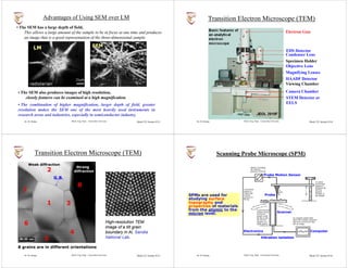


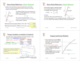


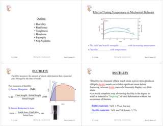


![Dr. M. Medraj Mech. Eng. Dept. - Concordia University MECH 221 lecture 22/1
In this lecture we shall answer the following questions
• How does a material respond to heat?
• How do we define and measure...
- heat capacity
- coefficient of thermal expansion
- thermal conductivity
- thermal shock resistance
• How do ceramics, metals, and polymers rank?
THERMAL PROPERTIES
Dr. M. Medraj Mech. Eng. Dept. - Concordia University MECH 221 lecture 22/2
The heat capacity, C, of a system is the ratio of the heat added to, or
withdrawn from the system, to the resultant change in the temperature:
Heat Capacity
- constant-volume heat capacity
- constant-pressure heat capacity
C = q/T = q/dT [J/mol-K]
This definition is only valid in the absence of …………………
Usually C is given as specific heat capacity, c, per gram or per mol
New state of the system is not defined by T only, need to specify or
constrain second variable:
cv and cp can be measured experimentally
Dr. M. Medraj Mech. Eng. Dept. - Concordia University MECH 221 lecture 22/3
• Heat capacity
- increases with temperature
- reaches a limiting value of 3R
• Atomic view:
- Energy is stored as atomic vibrations.
- As T goes up, so does the avg. energy of atomic vibration.
Heat Capacity Vs T
Adapted from Fig. 19.02,
Callister 8e.
Debye temperature
(usually less than Troom)
Cv= constant
gas constant
= 8.31 J/mol-K
Dr. M. Medraj Mech. Eng. Dept. - Concordia University MECH 221 lecture 22/4
Theoretical Calculation of the Heat Capacity
• In 1819 Dulong and Petit found experimentally that for many solids at
room temperature, cv 3R = …………...
Figure 6.1: Gaskell 3rd ed.
• Although cv for many elements (e.g.
lead and copper) at room temp. are
indeed close to 3R, cv values of
silicon and diamond are significantly
lower than 25J/K.mol.
• Low temp. measurements showed a
strong temperature dependence of cv.
Actually, cv 0 as T 0 K.
Calculation of heat capacity of solids, as a f(T), was one of the early
driving forces of the quantum theory. The first explanation was
proposed by ………… in 1906.](https://image.slidesharecdn.com/uck210eaerospacematerialsnotes1-250404163710-1174f475/85/UCK_210E_Aerospace_Materials_Notes-1-pdf-111-320.jpg)


![Dr. M. Medraj Mech. Eng. Dept. - Concordia University MECH 221 lecture 22/13
• Occurs due to uneven heating/cooling.
• Example: Assume top thin layer is rapidly cooled from T1 to T2:
rapid quench
doesn’t want to contract
tries to contract during cooling T2
T1
Tension develops at surface
E(T1 T2)
Critical temperature difference
for fracture (set = f)
(T1 T2)fracture
f
E
Temperature difference that
can be produced by cooling:
(T1 T2)
quench rate
k
set equal
• Result:
• Large thermal shock resistance when is large.
fk
E
(quench rate )for fracture
fk
E
Thermal Shock Resistance
reinf C-C
(1650ºC)
Re-entry T
Distribution
silica tiles
(400-1260ºC)
nylon felt, silicon rubber
coating (400ºC)
Dr. M. Medraj Mech. Eng. Dept. - Concordia University MECH 221 lecture 22/14
1. Maintain the temperature on the inner airframe below certain temp. [eg., 175°C] for a
maximum outer surface temperature of 1465°C.
2. Remain usable for 100 missions, with a maximum turnaround time of 160 h.
3. Provide and maintain an aerodynamically smooth outer surface.
4. Be constructed of low-density materials.
5. Withstand temperature extremes between -110°C and 1465°C.
6. Be resistant to severe thermal gradients and rapid temperature changes.
7. Be able to withstand stresses and vibrations that are experienced during launch, as
well as thermally induced stresses imposed during temperature changes.
8. Experience a minimum absorption of moisture and other contaminants during
storage between missions.
9. Be made to adhere to the airframe that is constructed of an aluminum alloy.
Space Shuttle Thermal Protection System
Fig. 19.2W, Callister 6e. • Materials developed
previously by the aerospace
industry are ………….. for the
shuttle
• They are too dense or non-
reusable
Is there a single
material which
satisfies all these
requirements?
Dr. M. Medraj Mech. Eng. Dept. - Concordia University MECH 221 lecture 22/15
FIGURE 23.17 Photograph showing the
installation of thermal protection ceramic
tiles on the Space Shuttle Orbiter.
Space Shuttle Thermal Protection System
• For regions that are exposed to higher
temperature (400 to 1260°C);
• ceramic tiles (more complex) are used
• because ceramics are thermal insulators
and can withstand high temperature.
• 24,300 tiles (70% or the exterior area)
• each tile is different
750X
SEM micrograph of a Space Shuttle Orbiter
ceramic tile showing silica fibers after sintering
Dr. M. Medraj Mech. Eng. Dept. - Concordia University MECH 221 lecture 22/16
A material responds to heat by:
increased vibrational energy
redistribution of this energy to achieve thermal equilibrium.
Heat capacity:
energy required to increase a unit mass by a unit temp.
polymers have the ……. values.
Coefficient of thermal expansion:
the stress-free strain induced by heating by a unit T.
polymers have the ……… values.
Thermal conductivity:
the ability of a material to transfer heat.
metals have the ……… values.
Thermal shock resistance:
the ability of a material to be rapidly cooled and not crack.
Maximize fk/E.
Summary](https://image.slidesharecdn.com/uck210eaerospacematerialsnotes1-250404163710-1174f475/85/UCK_210E_Aerospace_Materials_Notes-1-pdf-114-320.jpg)