Download as PPS, PPTX

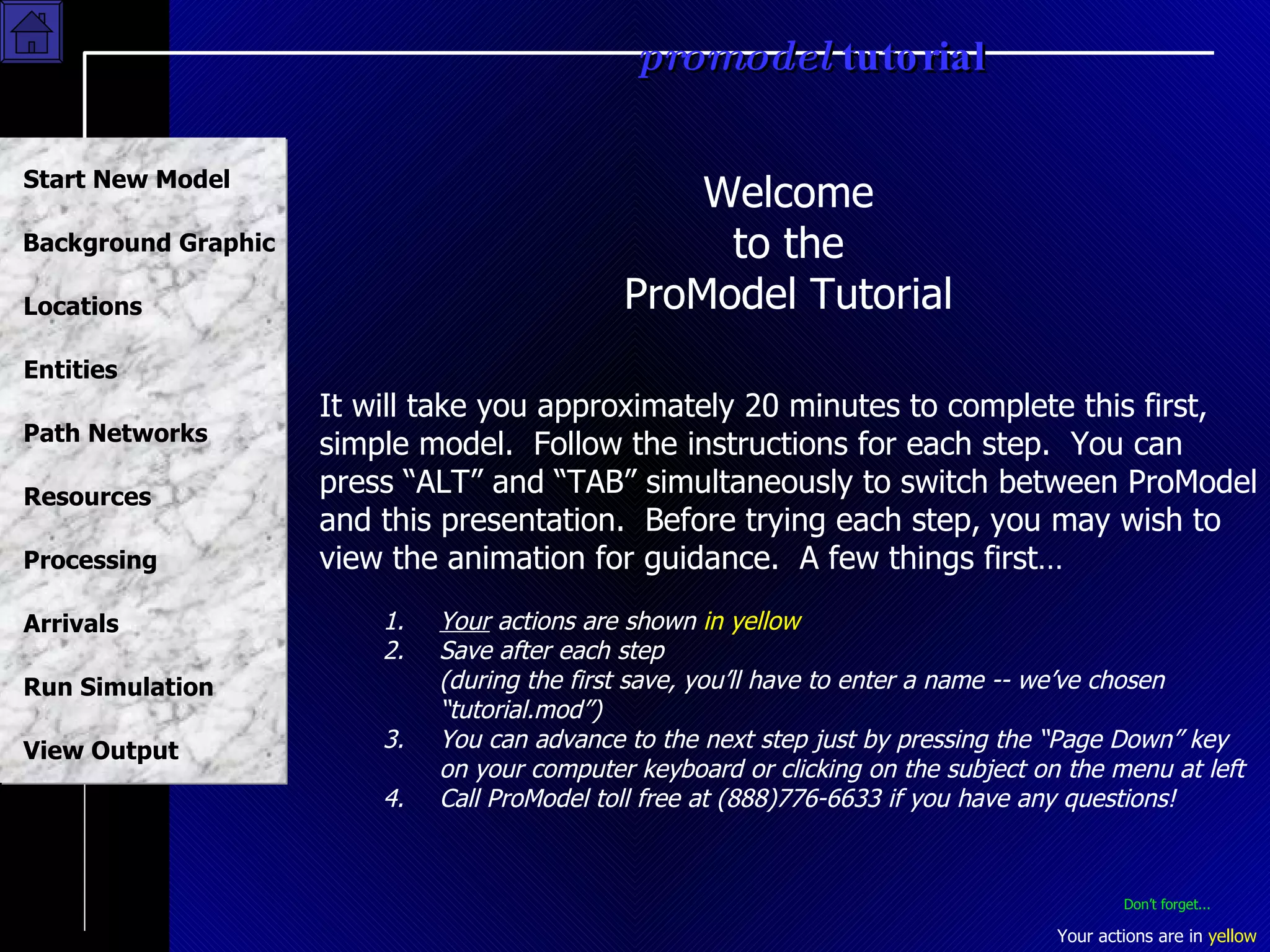
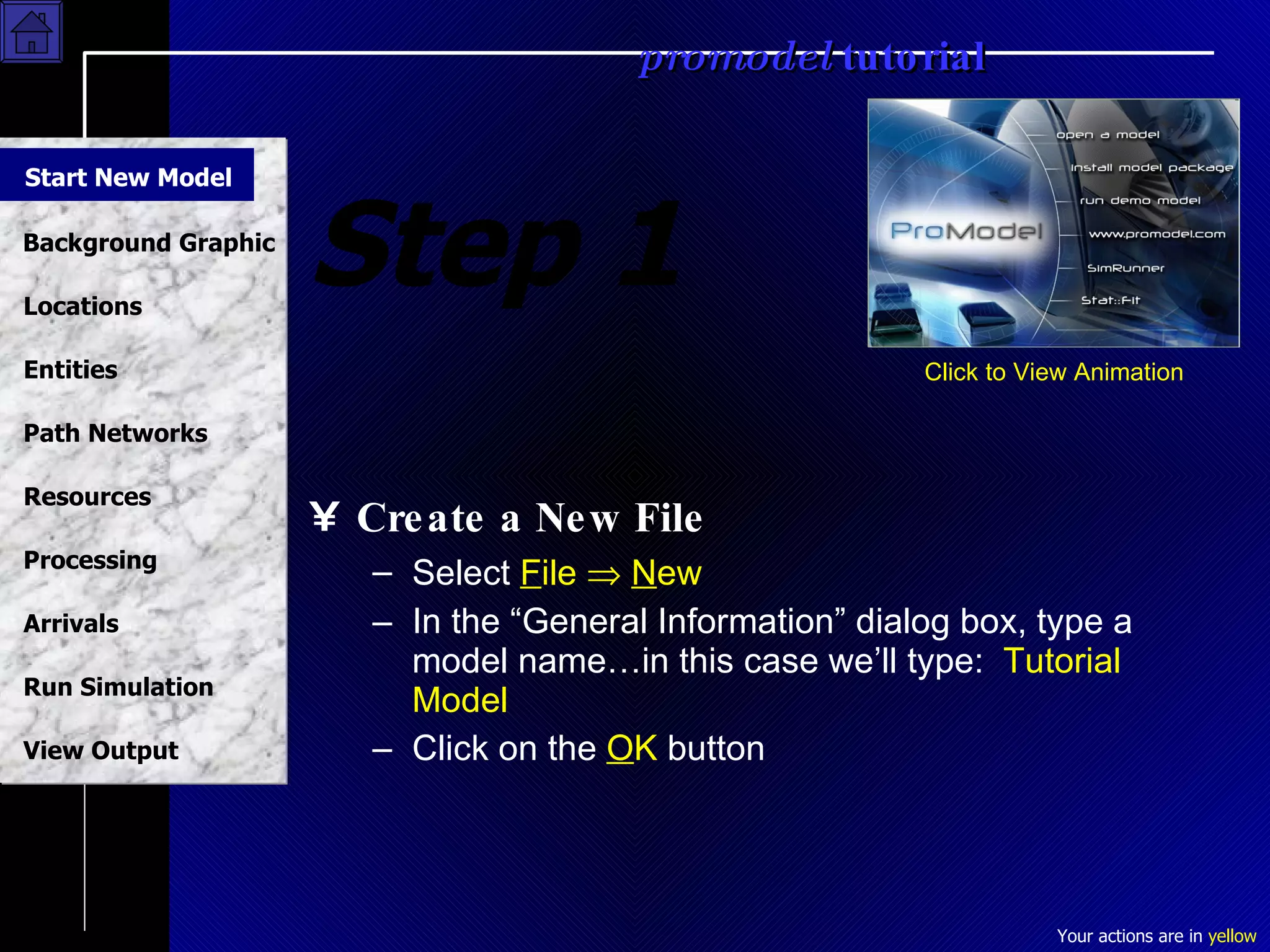
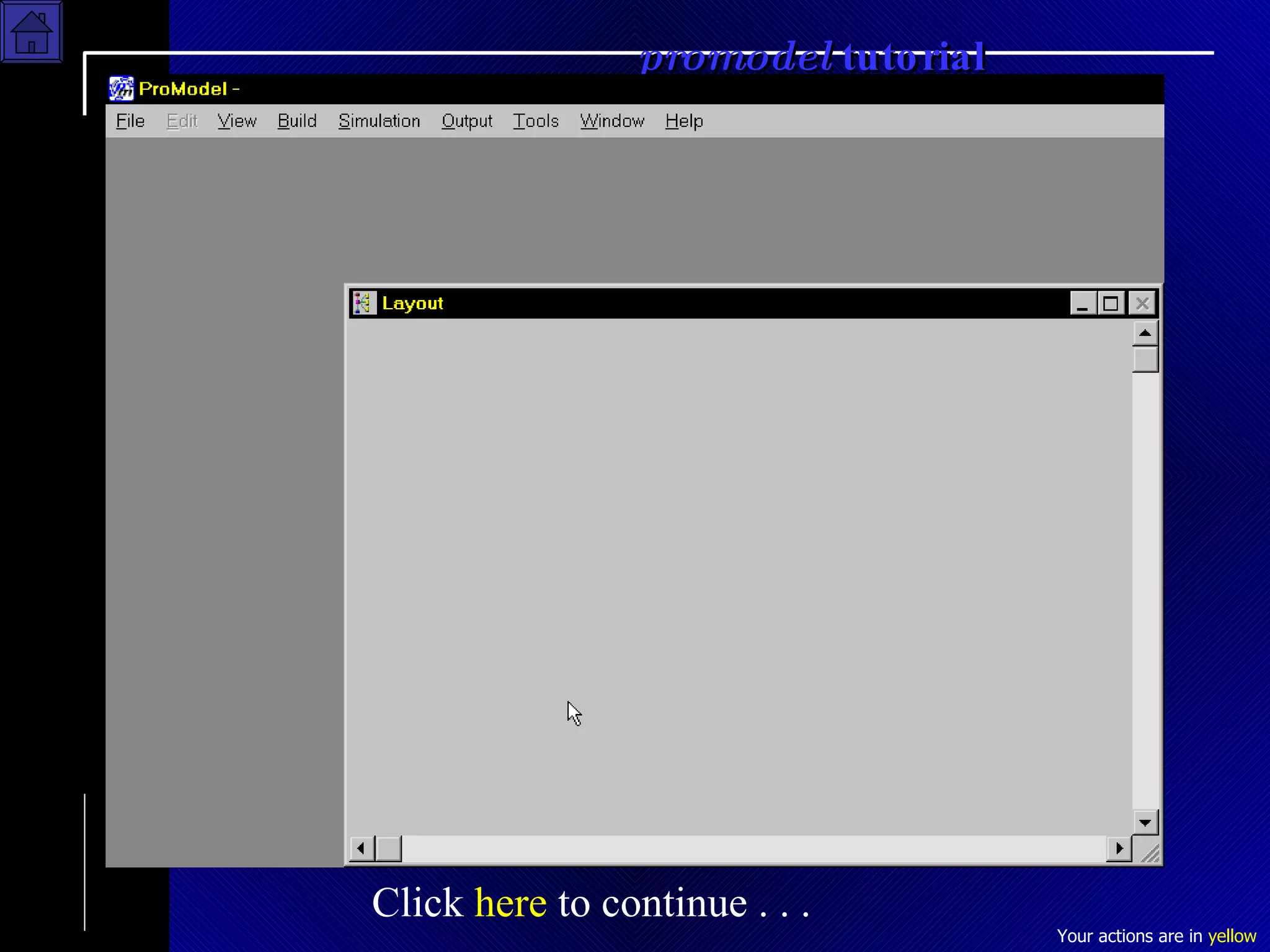
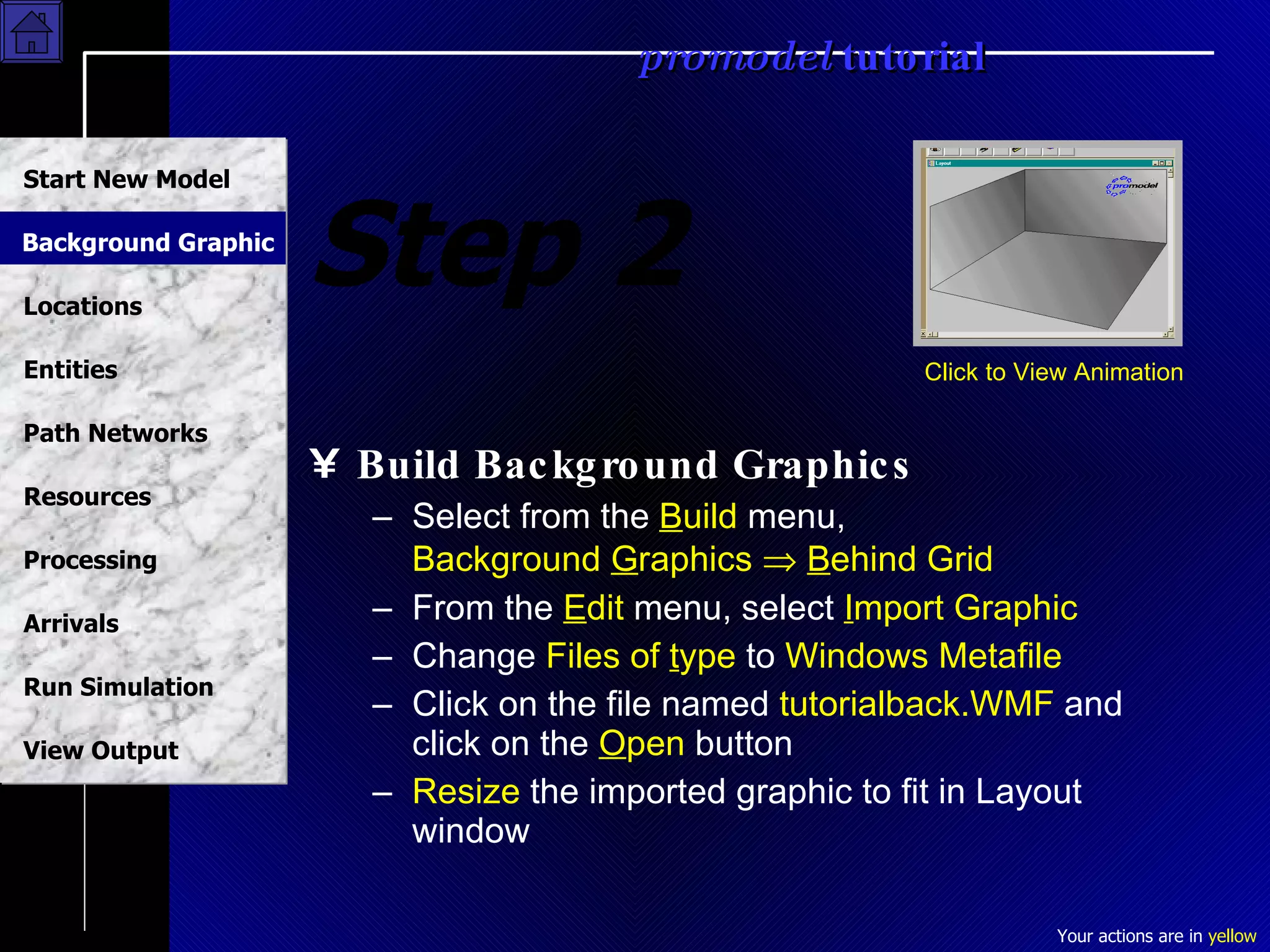
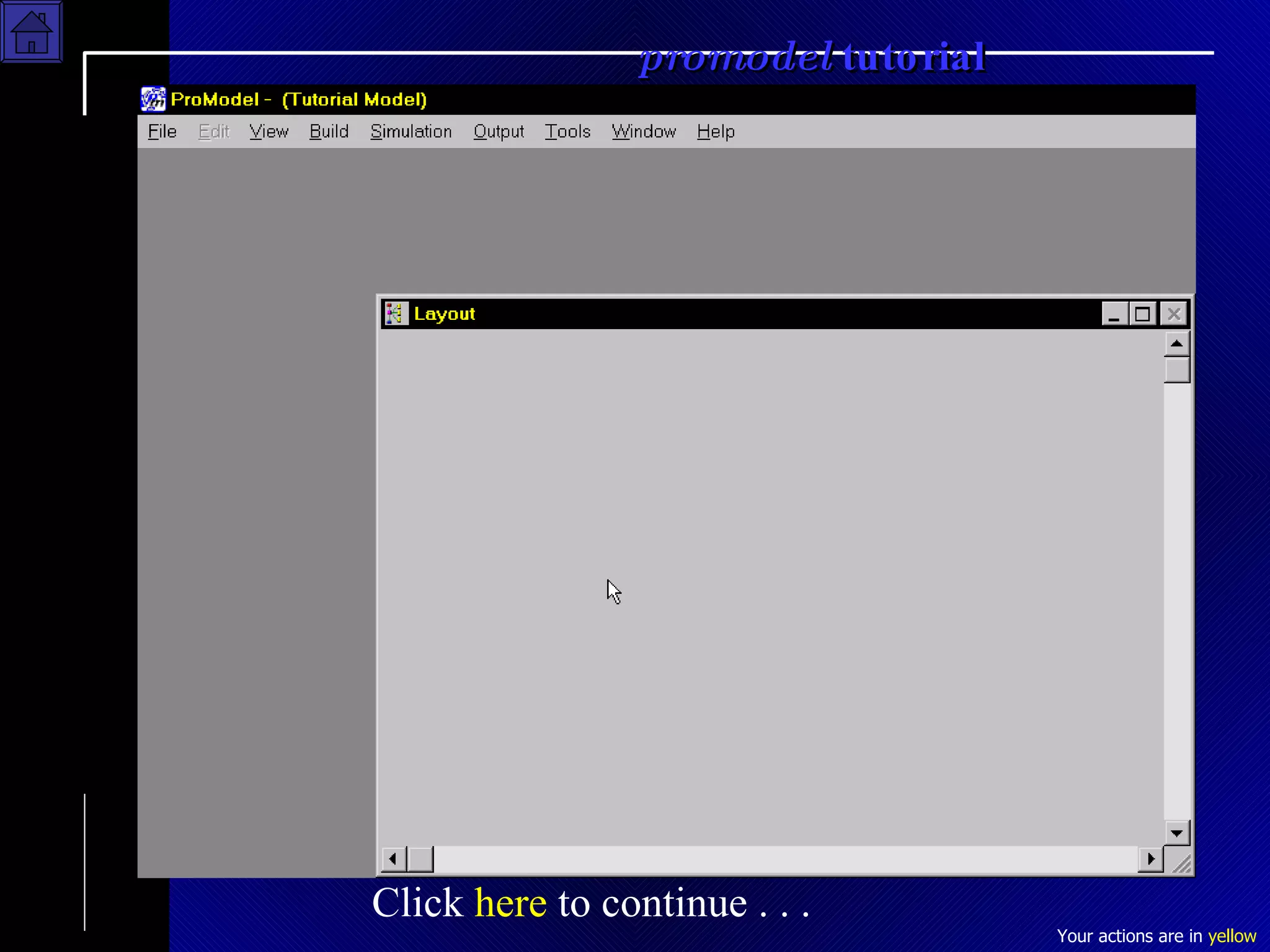
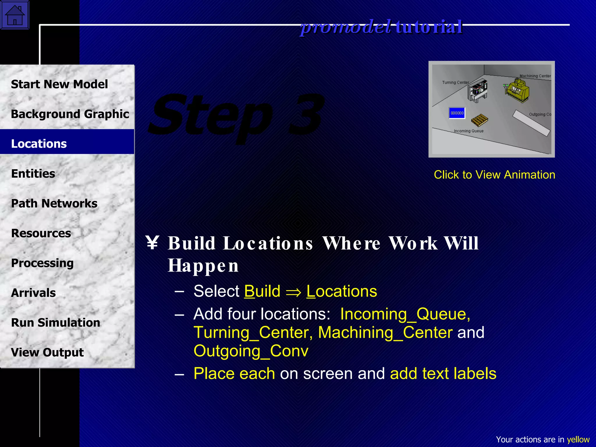

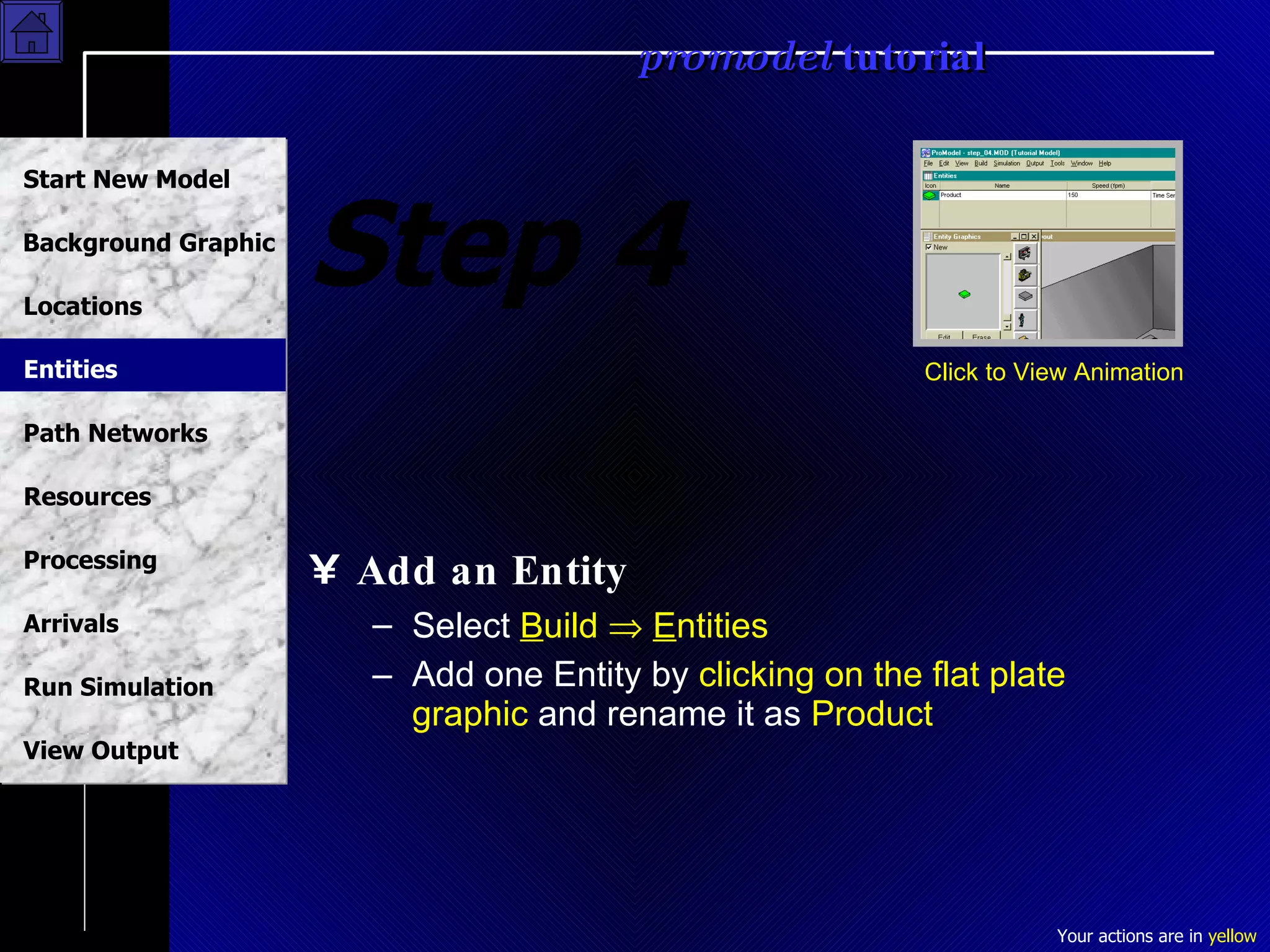
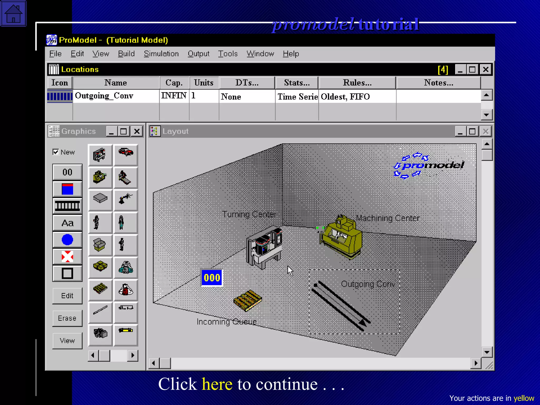
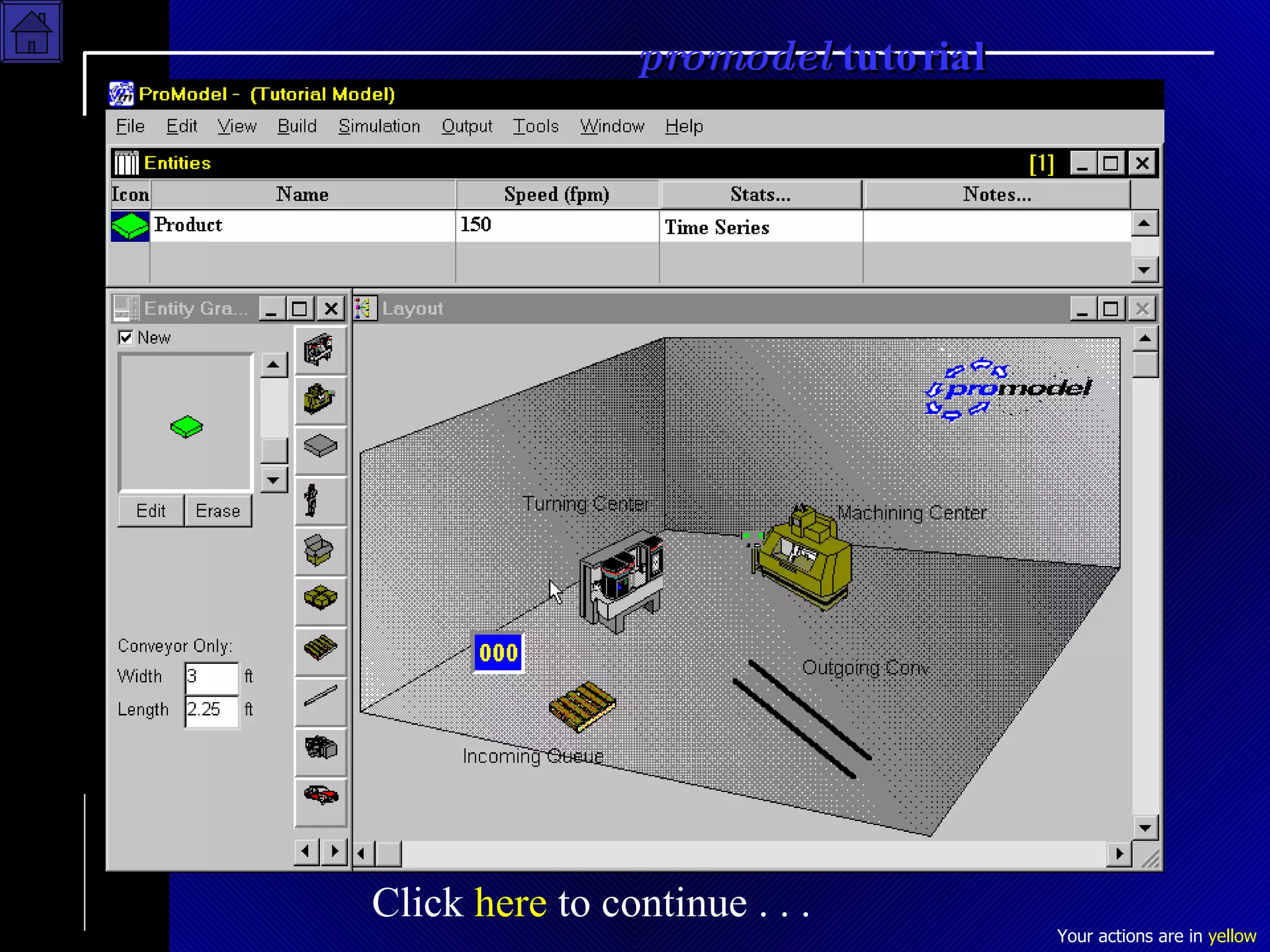
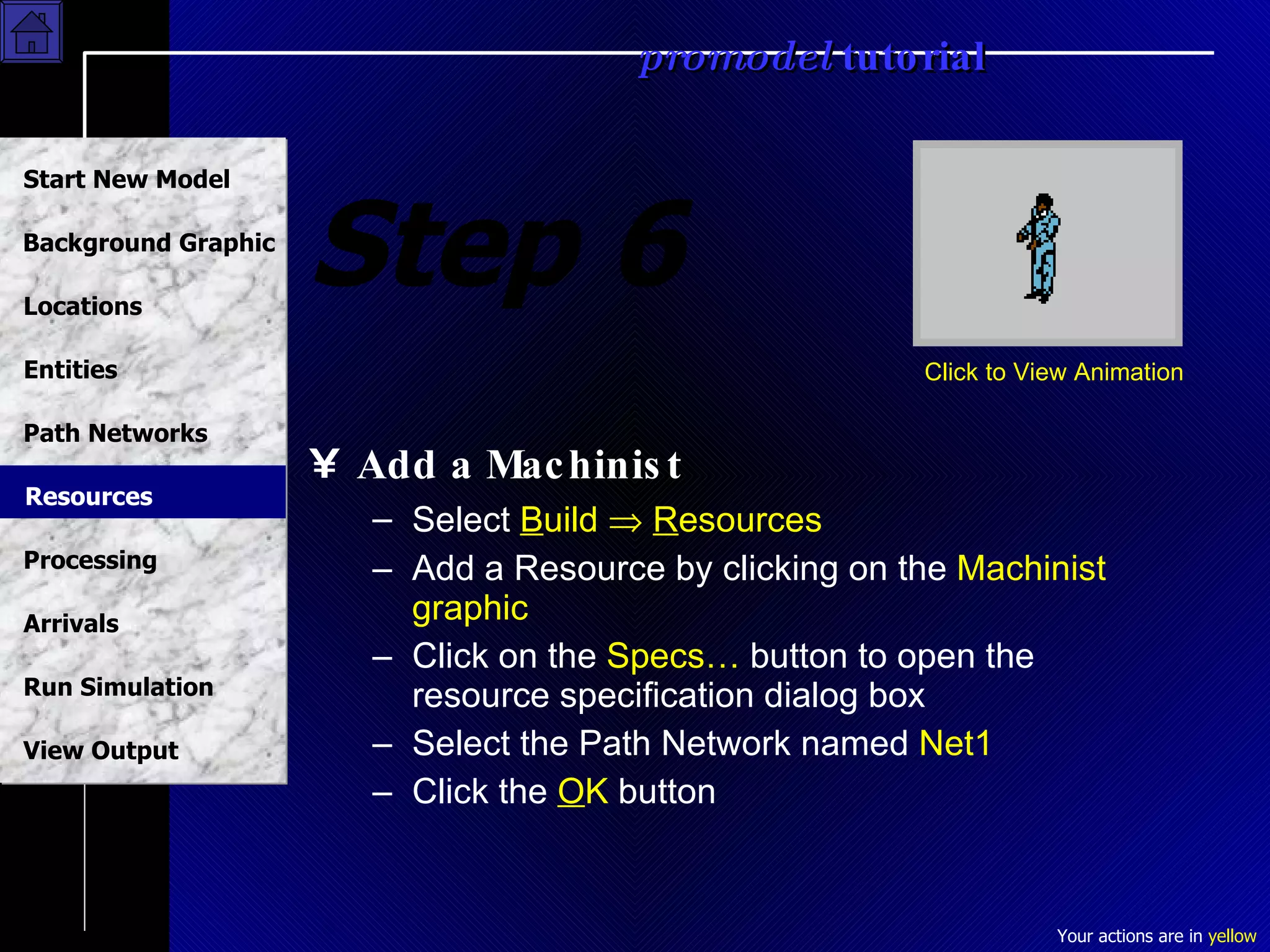
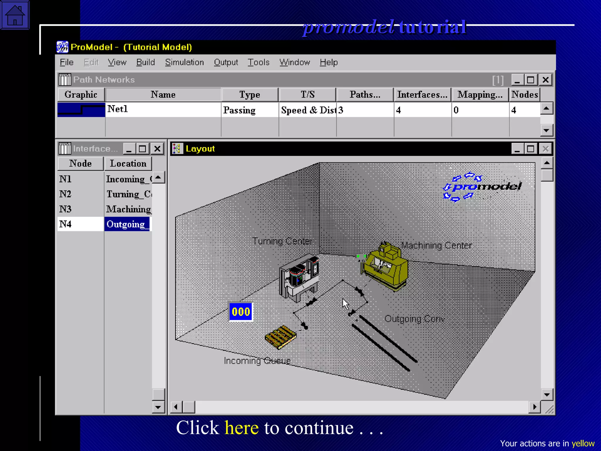
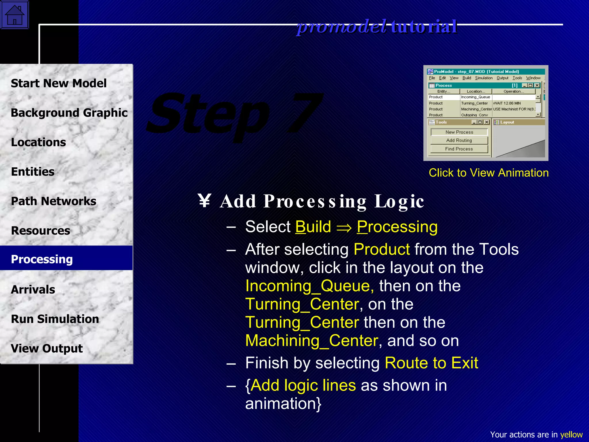
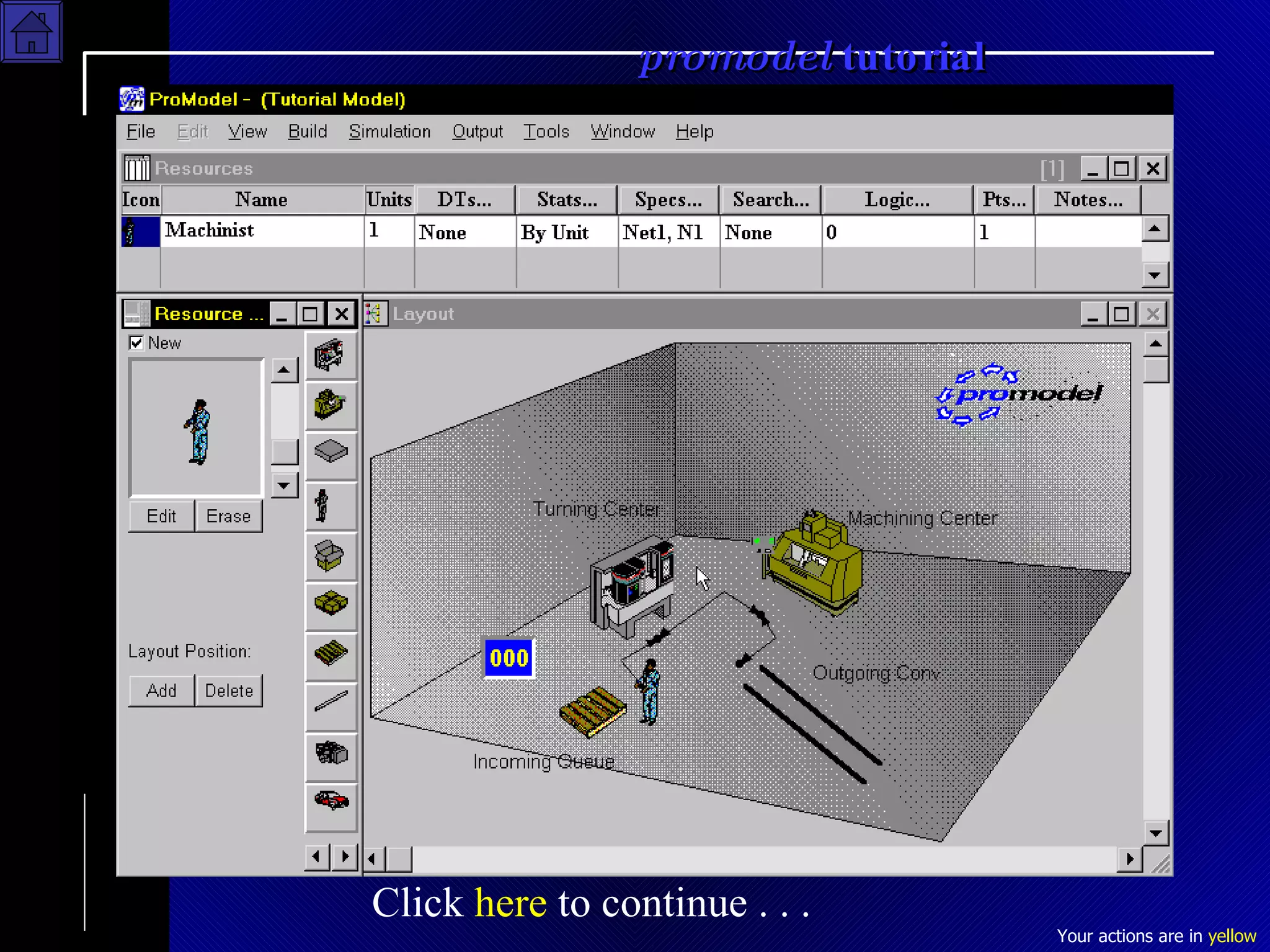
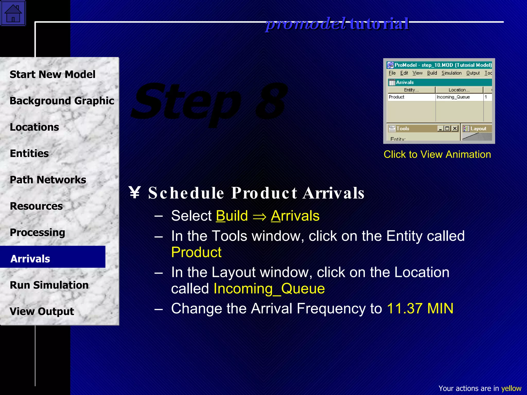
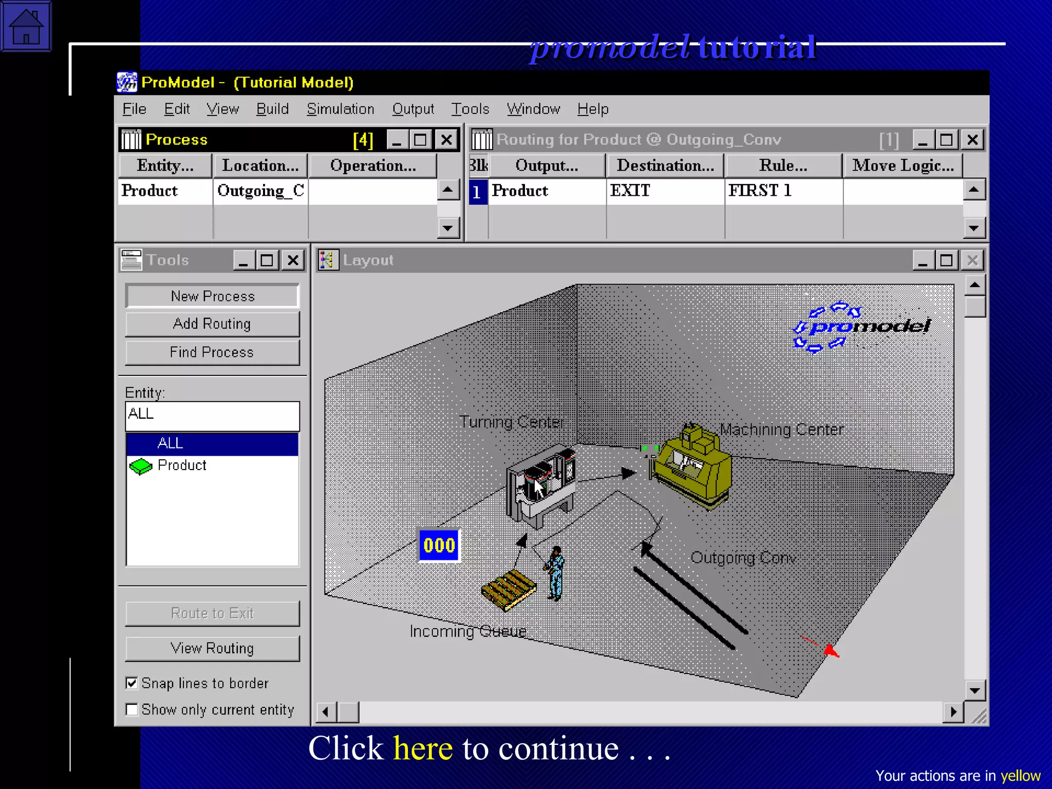
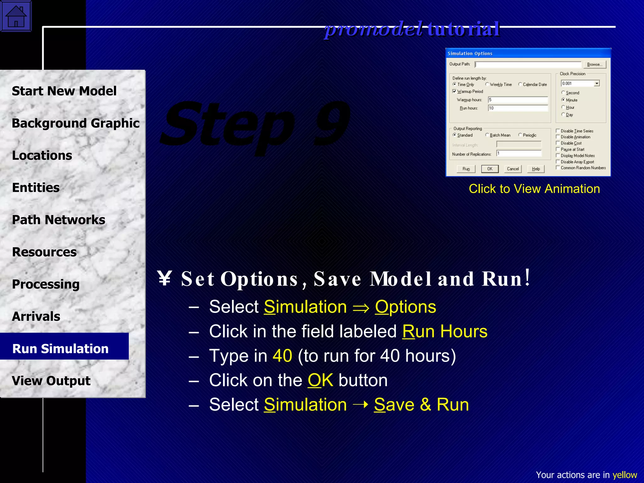
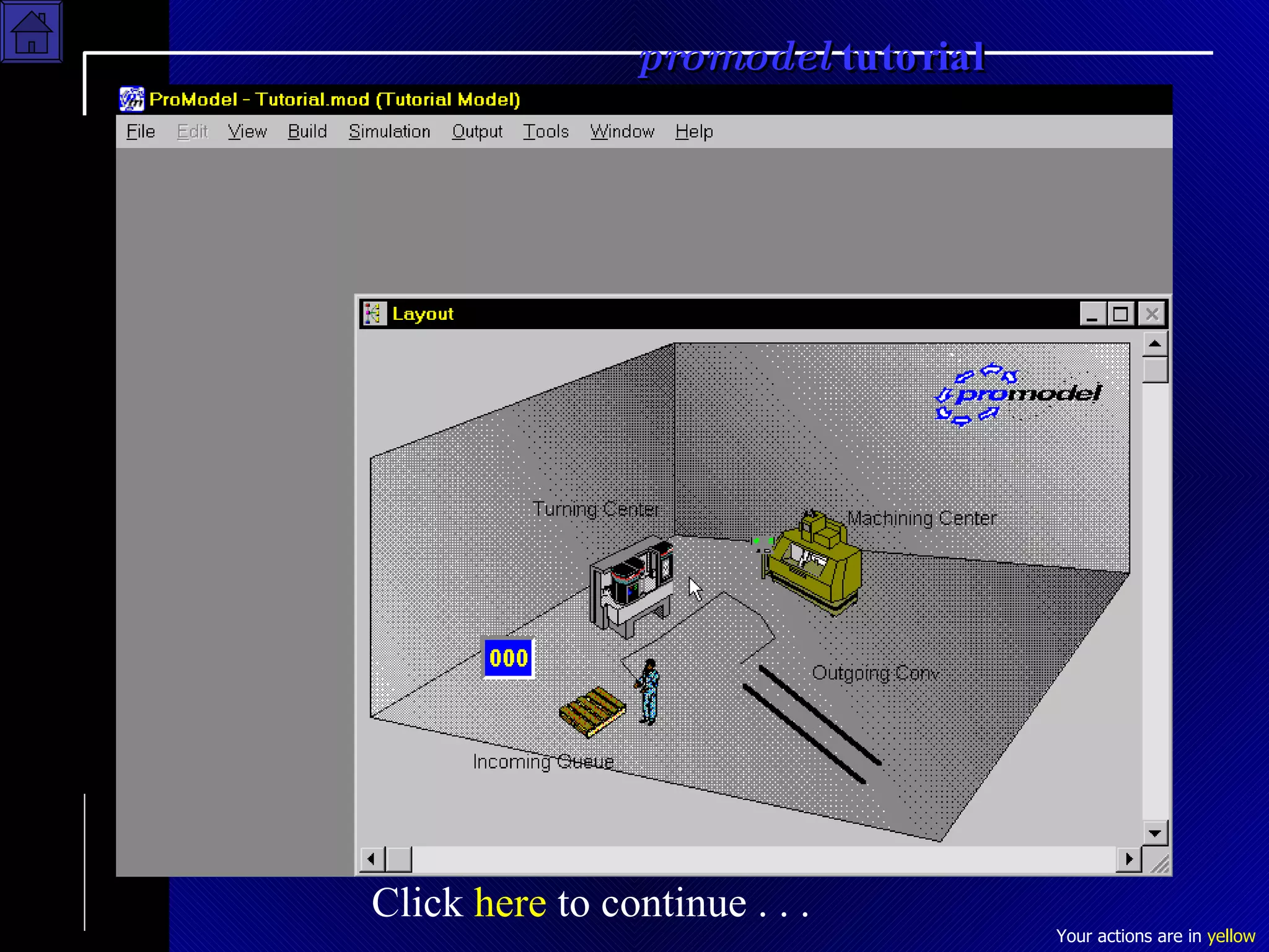
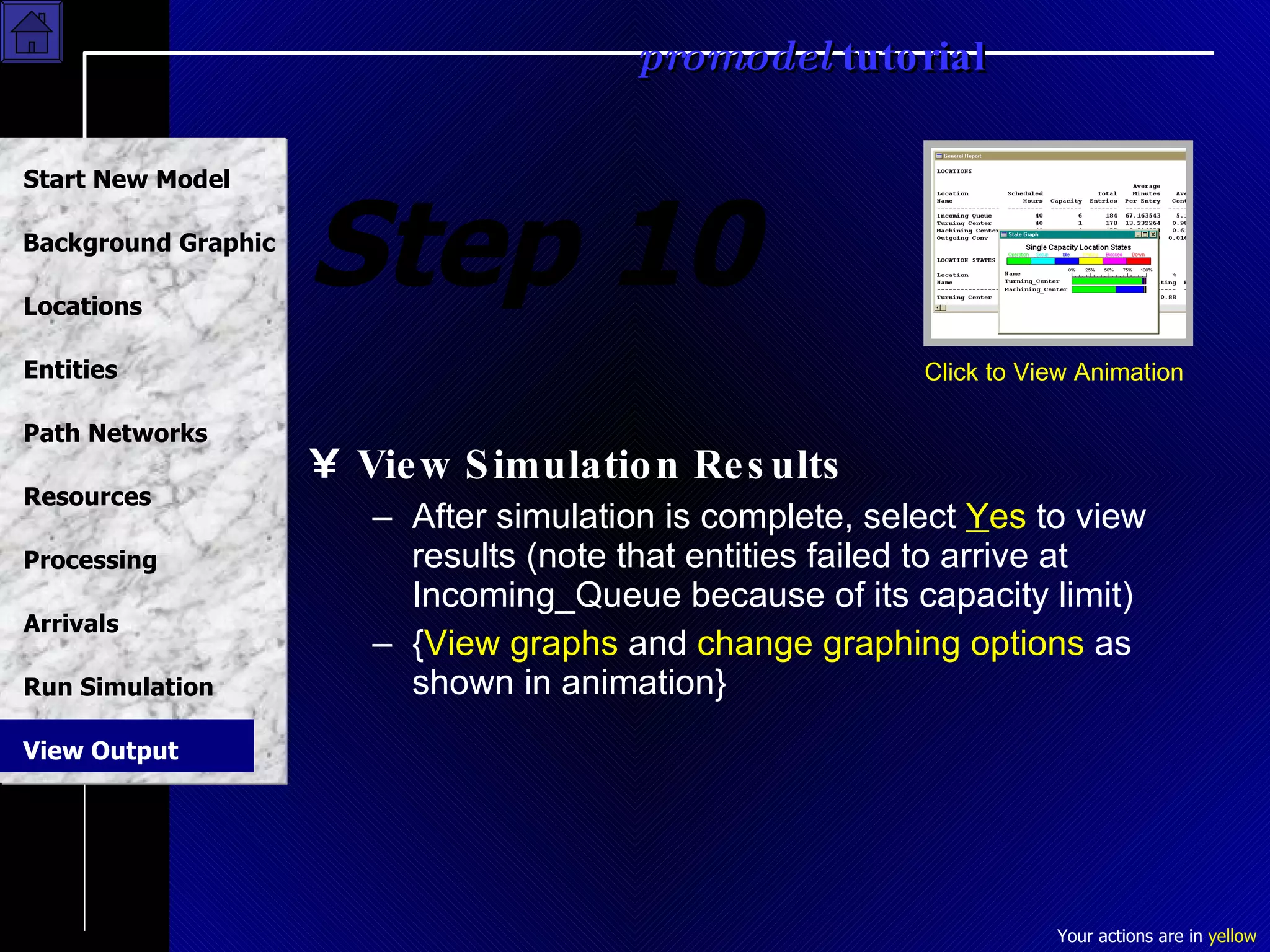
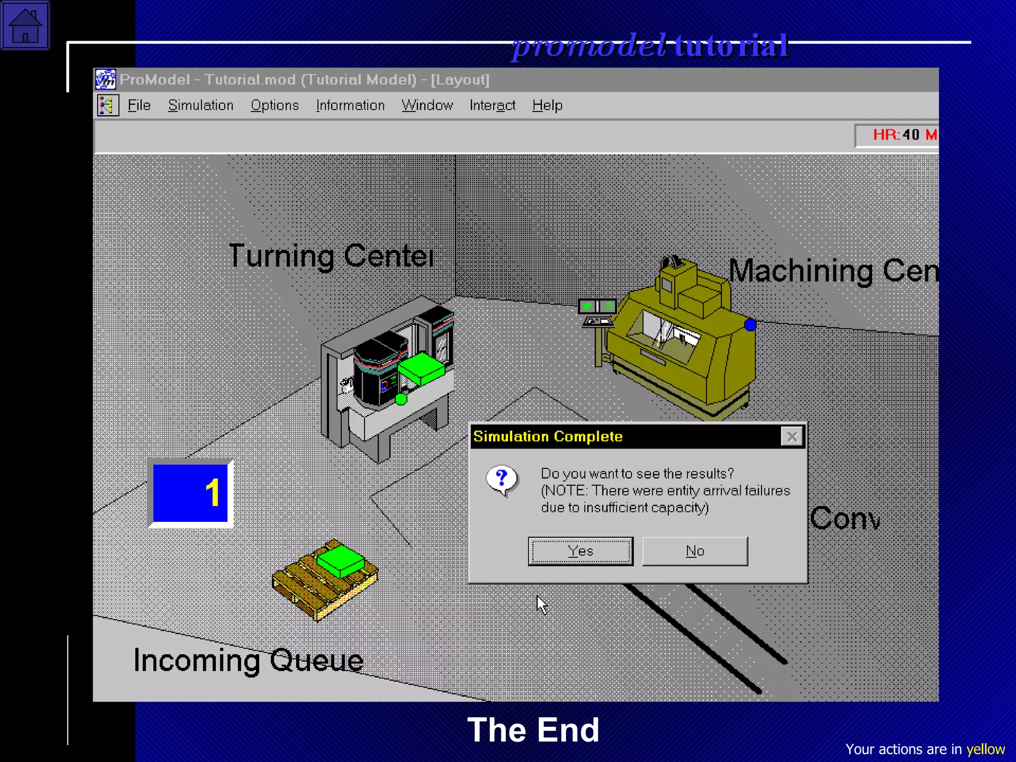

This tutorial provides step-by-step instructions for creating a simple ProModel simulation to demonstrate the basic functions. The simulation models a manufacturing process with four locations where work is done, one product entity, a machinist resource, and processing logic to route the product through the locations. The tutorial guides the user through building the model components, setting arrival frequencies, running the simulation for 40 hours, and viewing the results.