Download as PDF, PPTX

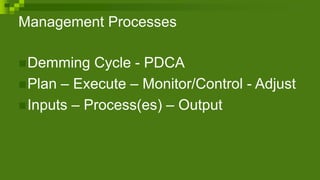
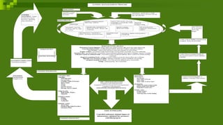
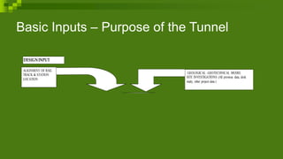
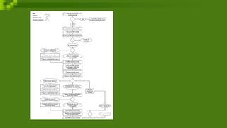
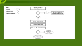

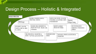


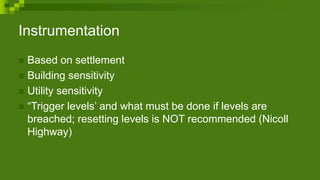
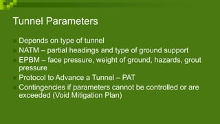
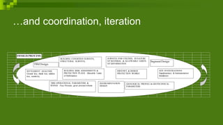
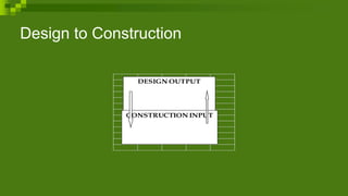
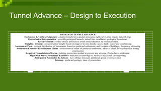


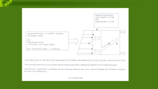


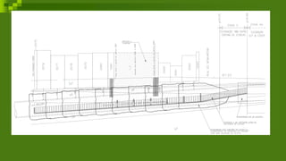

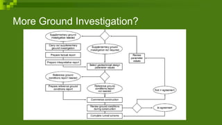
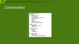


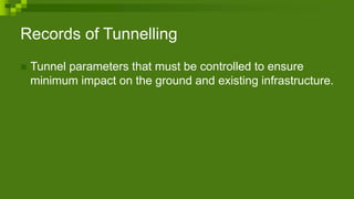
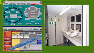


The document outlines the essential processes and management strategies for safe tunneling operations, emphasizing the importance of planning, monitoring, and controlling various parameters such as face pressure and ground conditions. It discusses the design input and output requirements, risk assessments, building condition surveys, and instrumentation needed to minimize settlement impacts on existing infrastructure. Overall, it highlights the critical role of thorough geological and geotechnical investigations, systematic monitoring, and contingency planning in ensuring successful tunneling projects.


